1
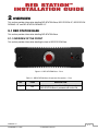
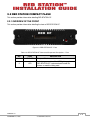
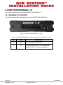
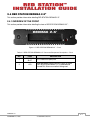
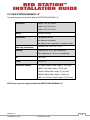
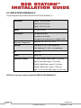
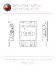
THIS PAGE
INTENTIONALLY BLANK
TABLE OF CONTENTS
1 INTRODUCTION ....................................................................... 1-1
1.1 Overview ...........................................................................................................................1-1
1.2 Safety Instructions ............................................................................................................1-4
1.3 System Requirements .......................................................................................................1-5
2 OVERVIEW ............................................................................... 2-1
2.1 RED STATION Base ..........................................................................................................2-1
2.1.1 Overview of the Front ............................................................................................2-1
2.1.2 Overview of the Rear .............................................................................................2-2
2.2 RED STATION Compact Flash ..........................................................................................2-3
2.2.1 Overview of the Front ............................................................................................2-3
2.2.2 Overview of the Rear .............................................................................................2-4
2.3 RED STATION REDMAG 1.8” ...........................................................................................2-5
2.3.1 Overview of the Front ............................................................................................2-5
2.3.2 Overview of the Rear .............................................................................................2-6
2.4 RED STATION REDMAG 2.5” ...........................................................................................2-7
2.4.1 Overview of the Front ............................................................................................2-7
2.4.2 Overview of the Rear .............................................................................................2-8
2.5 Connection Cables............................................................................................................2-9
2.5.1 RED STATION Base ..............................................................................................2-9
2.5.2 RED STATION Compact Flash / RED STATION REDMAG 1.8” /
RED STATION REDMAG 2.5” ......................................................................................2-9
3 SETUP AND OPERATION .......................................................... 3-1
3.1 Setup of RED STATION.....................................................................................................3-1
3.1.1 Connecting RED STATION Base and RED STATION Modules .............................. 3-1
3.1.2 Connecting RED STATION Module Stand-Alone ...................................................3-2
3.2 Operation of RED STATION ..............................................................................................3-3
3.2.1 Turning ON/OFF ....................................................................................................3-3
3.2.2 Startup of RED STATION .......................................................................................3-3
A APPENDIX ............................................................................... A-1
A.1 Technical Data ..................................................................................................................A-1
A.1.1 RED STATION Base ..............................................................................................A-1
A.1.2 RED STATION Compact Flash ..............................................................................A-2
A.1.3 RED STATION REDMAG 1.8”................................................................................A-3
A.1.4 RED STATION REDMAG 2.5”................................................................................A-4
Installation Guide for:
•
RED STATION™ Base
•
RED STATION™ REDMAG 1.8”
•
RED STATION™ Compact Flash (CF)
•
RED STATION™ REDMAG 2.5”
VERSION 1.0
November 23, 2010
1 INTRODUCTION
1.1 OVERVIEW
RED STATION™ Base, RED STATION CF, RED STATION REDMAG 1.8” and RED STATION REDMAG
2.5” are RED® accessories allowing for fast, reliable file transfer between CF cards, 1.8” and 2.5” Hard
Drives and your computer using FireWire FW800, USB 2.0 or eSATA. This guide instructs you in the installation and usage of RED STATION Base, RED STATION Compact Flash (CF), RED STATION REDMAG 1.8”
and RED STATION REDMAG 2.5”. RED STATION CF, RED STATION REDMAG 1.8” and RED STATION
REDMAG 2.5” can be linked together with RED STATION Base, or as stand-alone.
1 INTRODUCTION
Includes RED STATION Base, RED STATION CF, RED
STATION REDMAG 1.8” and RED STATION REDMAG
2.5” safety instructions and system requirements
2 OVERVIEW
Provides an overview of RED STATION Base, RED STATION CF, RED STATION REDMAG 1.8” and RED STATION REDMAG 2.5” components and connections
3 INSTALLATION
Describes connecting and using RED STATION Base,
RED STATION CF, RED STATION REDMAG 1.8” and
RED STATION REDMAG 2.5”
A APPENDIX
Provides technical details about RED STATION Base,
RED STATION CF, RED STATION REDMAG 1.8” and
RED STATION REDMAG 2.5”
DISCLAIMER
RED has made every effort to provide clear and accurate information in this Installation Guide, which is
provided solely for the user’s information. While thought to be accurate, the information in this document
is provided strictly “as is” and RED will not be held responsible for issues arising from typographical errors
or user’s interpretation of the language used herein that is different from that intended by RED. All safety
and general information is subject to change as a result of changes in local, federal or other applicable
laws.
RED reserves the right to revise this Installation Guide and make changes from time to time in the content
hereof without obligation to notify any person of such revisions or changes. In no event shall RED, its employees or authorized agents be liable to you for any damages or losses, direct or indirect, arising from
the use of any technical or operational information contained in this document.
USE AT YOUR OWN RISK - RED is not responsible for lost/corrupted data or damaged CF Cards,
1.8” SSD’s or 2.5” SSD’s while using RED STATION Base, RED STATION CF, RED STATION REDMAG 1.8”, or RED STATION REDMAG 2.5”.
VERSION 1.0
NOVEMBER 23, 2010
1-1
© 2010 RED.COM, INC.
COPYRIGHT NOTICE
© 2010 Red.com, Inc.
All trademarks, trade names, logos, icons, images, written material, code, and product names used in association with the accompanying product are the copyrights, trademarks or other intellectual property
owned and controlled exclusively by RED.com, Inc.
COMPLIANCE
INDUSTRIAL CANADA EMISSION COMPLIANCE STATEMENTS
This Class B digital apparatus complies with Canadian ICES-003.
Cet appareil numérique de la classe B est conforme à la norme NMB-003 du Canada.
FEDERAL COMMUNICATIONS COMMISSION (FCC) STATEMENT
This equipment has been tested and found to comply with the limits for a Class B digital device, pursuant to part 15 of the FCC Rules. These limits are designed to provide reasonable
protection against harmful interference in a residential installation. This equipment generates,
uses and can radiate radio frequency energy and, if not installed and used in accordance
with the instructions, may cause harmful interference to radio communications. However, there is no
guarantee that interference will not occur in a particular installation. If this equipment does cause harmful
interference to radio or television reception, which can be determined by turning the equipment off and
on, the user is encouraged to try to correct the interference by one or more of the following measures:
•
Reorient or relocate the receiving antenna.
•
Increase the separation between the equipment and receiver.
•
Connect the equipment into an outlet on a circuit different from that to which the receiver is connected.
•
Consult the dealer or an experienced technician for help.
NOTE: This device complies with Part 15 of the FCC Rules.
Operations subject to the following two conditions: (1) this device may not cause harmful interference, and
(2) this device must accept any interference received, including interference that may cause undesirable
interference.
CAUTION: If the device is changed or modified without permission from RED, the user may void his
or her authority to operate the equipment.
AUSTRALIA AND NEW ZEALAND STATEMENT
This device has been tested and found to comply with the limits for a Class B digital device, pursuant to EN
55022:2006
JAPAN STATEMENTS
This is a Class B product based on the standard of the Voluntary Control Council for Interference (VCCI) for information technology equipment. If this equipment is used near a radio or
television receiver in a domestic environment, it may cause radio interference. Install and use
the equipment according to the instruction manual.
VERSION 1.0
1-2
© 2010 RED.COM, INC.
NOVEMBER 23, 2010
EUROPEAN UNION COMPLIANCE STATEMENTS
RED declares that the equipment described in this document is in conformance with
the requirements of the European Council EMC Directive 2004/108/EC, Low Voltage
Directive 2006/95/EC, RoHS Directive 2002/95/EC and WEEE Directive 2002/96/EC.
This declaration is based upon compliance of the product to the following standards:
•
EN 55022, Information Technology Equipment - Radio Disturbance Characteristics
•
EN 55024, Information Technology Equipment - Immunity Characteristics
•
EN 61000-3-2, Limits for harmonic current emissions
•
EN 61000-3-3, Limits for harmonic current emissions
•
EN 60950-1, Information Technology Equipment – Safety
The Waste Electrical and Electronic Equipment (WEEE) mark applies only to countries
within the European Union (EU) and Norway. This symbol on the product and accompanying documents means that used electrical and electronic products should not be mixed
with general household waste. For proper treatment, recovery and recycling, please take
this product to designated collection points where it will be accepted free of charge. Alternatively, in some countries you may be able to return your products to your local retailer
upon purchase of an equivalent new product.
Disposing of this product correctly will help save valuable resources and prevent any potential negative
effects on human health and the environment, which could otherwise arise from inappropriate waste handling. Please contact your local authority for further details of your nearest designated collection point.
Penalties may be applicable for incorrect disposal of this waste, in accordance with you national legislation.
For business users in the European Union, If you wish to discard electrical and electronic equipment,
please contact your dealer or supplier for further information.
Responsible party:
Red.com, Inc. dba Red Digital Cinema
20291 Valencia Circle
Lake Forest, CA 92630
USA
VERSION 1.0
NOVEMBER 23, 2010
1-3
© 2010 RED.COM, INC.
1.2 SAFETY INSTRUCTIONS
CAUTION: Please read the following safety instructions very carefully before attempting installation
of RED STATION Base, RED STATION CF, RED STATION REDMAG 1.8” and RED STATION REDMAG 2.5”.
CAUTION: If RED STATION Base, RED STATION CF, RED STATION REDMAG 1.8” and RED STATION REDMAG 2.5” are not used in compliance with the safety instructions, the warranty and all
resulting liability claims will be void.
To use RED STATION Base, RED STATION CF, RED STATION REDMAG 1.8” and RED STATION REDMAG 2.5” correctly please adhere to the following:
GENERAL
RED STATION Base, RED STATION CF, RED STATION REDMAG 1.8” and RED STATION REDMAG 2.5”
have been built according to applicable safety regulations. To minimize the possibility of faulty operation
of these devices, all manuals and guides should be available at the operation site. Before installing and/or
using RED STATION Base, RED STATION CF, RED STATION REDMAG 1.8” or RED STATION REDMAG
2.5”, the Installation Guide must be read and adhered to.
-
Use RED STATION only when in good operating condition.
-
Use RED STATION in compliance with the technical data outlined in section A-1 TECHNICAL DATA.
-
If fluid or foreign objects get inside RED STATION Base, RED STATION CF, RED STATION REDMAG
1.8” or RED STATION REDMAG 2.5”, disconnect from the power source immediately. Before using
RED STATION Base, RED STATION CF, RED STATION REDMAG 1.8” or RED STATION REDMAG
2.5” again, contact RED technical support.
-
To clean RED STATION casings, use a damp cloth without any cleaning agents
-
RED STATION must not be misused, abused, physically damaged, neglected, exposed to fire, water
or excessive changes in the climate or temperature, or operated outside maximum rating. Refer to A.1
TECHNICAL DATA.
-
Do not open, tamper with, attempt to dismantle or perform any changes or modifications to RED
STATION whatsoever.
TRANSPORTATION
During transportation of RED STATION please observe the following:
-
Always use the original packaging or a similar structured packaging for transportation.
-
Keep RED STATION Base, RED STATION CF, RED STATION REDMAG 1.8” and RED STATION
REDMAG 2.5” away from humidity and moisture during transportation.
VERSION 1.0
1-4
© 2010 RED.COM, INC.
NOVEMBER 23, 2010
ENVIRONMENTAL CONDITIONS
For proper operation and long service life of your RED STATION Base, RED STATION CF, RED STATION
REDMAG 1.8” and RED STATION REDMAG 2.5”, please adhere to these basic environmental condition
requirements:
-
DO NOT expose RED STATION Base, RED STATION CF, RED STATION REDMAG 1.8” or RED STATION REDMAG 2.5” to sources of heat, such as direct sunlight or a heating source.
-
AVOID areas with high humidity or dust.
-
DO NOT expose RED STATION Base, RED STATION CF, RED STATION REDMAG 1.8” or RED STATION REDMAG 2.5” to vibration.
-
DO NOT expose RED STATION Base, RED STATION CF, RED STATION REDMAG 1.8” or RED STATION REDMAG 2.5” to strong electric or magnetic fields.
-
RED STATION Base, RED STATION CF, RED STATION REDMAG 1.8” and RED STATION REDMAG
2.5” will operate best in an air-conditioned environment.
1.3 SYSTEM REQUIREMENTS
REQUIRED HARDWARE
For proper use of RED STATION Base, RED STATION CF, RED STATION REDMAG 1.8” and RED STATION REDMAG 2.5”, ensure you are using a computer equipped with one or more of the following ports:
•
•
•
USB 2.0
eSATA
FireWire FW800
IMPORTANT: ONLY Silicon Image or Highpoint SATA cards will connect to RED STATION modules
through eSATA at this time.
RED STATION REDMAG 1.8”
For proper operation of RED STATION REDMAG 1.8”, ensure you are using one of the following approved
1.8” Hard Drives:
•
All RED 1.8” Hard Drives (SSD’s)
RED STATION REDMAG 2.5”
For proper operation of RED STATION REDMAG 2.5”, ensure you are using one of the following approved
2.5” Hard Drives:
•
•
•
•
•
Seagate 2.5” Desktop Hard Drive 5400 RPM, 320GB. Model number ST9320325AS
Seagate 2.5” Desktop Hard Drive 5400 RPM, 500GB. Model number ST9500325AS
Seagate 2.5” Desktop Hard Drive 7200 RPM, 250GB. Model number ST9250410AS
Seagate 2.5” Desktop Hard Drive 7200 RPM, 320GB. Model number ST9320423AS
Western Digital 2.5” Desktop Hard Drive 7200 RPM, 320GB (Black). Model number WD3200BJKT
VERSION 1.0
NOVEMBER 23, 2010
1-5
© 2010 RED.COM, INC.
THIS PAGE
INTENTIONALLY BLANK
2 OVERVIEW
This section provides information detailing RED STATION Base, RED STATION CF, RED STATION
REDMAG 1.8” and RED STATION REDMAG 2.5”.
2.1 RED STATION BASE
This section provides information detailing RED STATION Base.
2.1.1 OVERVIEW OF THE FRONT
This section provides information detailing the front of RED STATION Base.
1
Figure 2-1: RED STATION Base - Front
Table 2-1: RED STATION Base Component Descriptions – Front
NO.
ITEM
1
LED
DESCRIPTION
Indicates power status; Red LED lights up when
RED STATION Base is powered and turned ON
VERSION 1.0
NOVEMBER 23, 2010
2-1
© 2010 RED.COM, INC.
2.1.2 OVERVIEW OF THE REAR
This section provides information detailing the rear of RED STATION Base.
1
2
3
Figure 2-2: RED STATION Base – Rear
Table 2-2: RED STATION Base Connector/Component Descriptions - Rear
NO.
ITEM
DESCRIPTION
1
POWER
Allows RED STATION Base to power up to three
(3) RED STATION modules
2
+5V DC IN
Power supply input for RED STATION Base; for
specifications see section A.1 TECHNICAL DATA
3
ON/OFF
SWITCH
Turns RED STATION Base ON or OFF
3
5
4
VERSION 1.0
2-2
© 2010 RED.COM, INC.
NOVEMBER 23, 2010
2.2 RED STATION COMPACT FLASH
This section provides information detailing RED STATION CF.
2.2.1 OVERVIEW OF THE FRONT
This section provides information detailing the front of RED STATION CF.
1
2
Figure 2-3: RED STATION CF – Front
Table 2-3: RED STATION CF Connector/Component Descriptions – Front
NO.
ITEM
1
CF SLOT
2
LED
DESCRIPTION
Compact Flash card slot
Indicates power status; Red LED lights up when
RED STATION CF is powered and turned ON;
flickers as media is being read
VERSION 1.0
NOVEMBER 23, 2010
2-3
© 2010 RED.COM, INC.
2.2.2 OVERVIEW OF THE REAR
This section provides information detailing the rear of RED STATION CF.
1
3
2
4
5
6
7
8
Figure 2-4: RED STATION CF – Rear
Table 2-4: RED STATION CF Connector/Component Descriptions
NO.
ITEM
DESCRIPTION
1-2
POWER
Can accept power from any RED STATION module that is already connected to RED STATION
Base; can also output power to another RED STATION module in stand-alone configuration or when
powered by RED STATION Base
3
ESATA
Allows RED STATION CF to connect to computer
via eSATA Connection
4-5
FIREWIRE 800
Allows RED STATION CF to connect to computer
via FW800 Connection; also allows RED STATION
CF to connect to additional RED STATION modules
6
MINI-USB
Allows RED STATION CF to connect to computer
via mini-USB Connection
7
ON/OFF
SWITCH
8
+5V DC IN
Turns RED STATION CF ON or OFF
Power supply input for RED STATION CF; for specifications see section A.1 TECHNICAL DATA
VERSION 1.0
2-4
© 2010 RED.COM, INC.
NOVEMBER 23, 2010
2.3 RED STATION REDMAG 1.8”
This section provides information detailing RED STATION REDMAG 1.8”.
2.3.1 OVERVIEW OF THE FRONT
This section provides information detailing the front of RED STATION REDMAG 1.8”.
1
2
Figure 2-5: RED STATION REDMAG 1.8” – Front
Table 2-5: RED STATION REDMAG 1.8” Connector/Component Descriptions – Front
NO.
1
2
ITEM
1.8” DRIVE
SLOT
LED
DESCRIPTION
1.8” RED Hard Drive (SSD) slot
Indicates power status; Red LED lights up when
RED STATION REDMAG 1.8” is powered and
turned ON; flickers as media is being read
VERSION 1.0
NOVEMBER 23, 2010
2-5
© 2010 RED.COM, INC.
2.3.2 OVERVIEW OF THE REAR
This section provides information detailing the rear of RED STATION REDMAG 1.8”.
1
2
3
4
5
6
7
8
Figure 2-6: RED STATION REDMAG 1.8” – Rear
Table 2-6: RED STATION REDMAG 1.8” Connector/Component Descriptions
NO.
ITEM
DESCRIPTION
1-2
POWER
Can accept power from any RED STATION module that is already connected to RED STATION
Base; can also output power to another RED STATION module in stand-alone configuration or when
powered by RED STATION Base
3
ESATA
Allows RED STATION REDMAG 1.8” to connect to
computer via eSATA Connection
4-5
FIREWIRE 800
Allows RED STATION REDMAG 1.8” to connect to
computer via FW800 Connection; also allows RED
STATION REDMAG 1.8” to connect to additional
RED STATION modules
6
MINI-USB
Allows RED STATION REDMAG 1.8” to connect to
computer via mini-USB Connection
7
ON/OFF
SWITCH
8
+5V DC IN
Turns RED STATION REDMAG 1.8” ON or OFF
Power supply input for RED STATION REDMAG
1.8”; for specifications see section A.1 TECHNICAL DATA
VERSION 1.0
2-6
© 2010 RED.COM, INC.
NOVEMBER 23, 2010
2.4 RED STATION REDMAG 2.5”
This section provides information detailing RED STATION REDMAG 2.5”.
2.4.1 OVERVIEW OF THE FRONT
This section provides information detailing the front of RED STATION REDMAG 2.5”.
1
2
Figure 2-7: RED STATION REDMAG 2.5” – Front
Table 2-7: RED STATION REDMAG 2.5” Connector/Component Descriptions – Front
NO.
1
2
ITEM
2.5” DRIVE
SLOT
LED
DESCRIPTION
2.5” Hard Drive (SSD) slot
Indicates power status; Red LED lights up when
RED STATION REDMAG 2.5” is powered and
turned ON; flickers as media is being read
VERSION 1.0
NOVEMBER 23, 2010
2-7
© 2010 RED.COM, INC.
2.4.2 OVERVIEW OF THE REAR
This section provides information detailing the rear of RED STATION REDMAG 2.5”.
1
2
3
4
5
6
7
8
Figure 2-8: RED STATION REDMAG 2.5” – Rear
Table 2-8: RED STATION REDMAG 2.5” Connector/Component Descriptions
NO.
ITEM
DESCRIPTION
1-2
POWER
Can accept power from any RED STATION module that is already connected to RED STATION
Base; can also output power to another RED STATION module in stand-alone configuration or when
powered by RED STATION Base
3
ESATA
Allows RED STATION REDMAG 2.5” to connect to
computer via eSATA Connection
4-5
FIREWIRE 800
Allows RED STATION REDMAG 2.5” to connect to
computer via FW800 Connection; also allows RED
STATION REDMAG 2.5” to connect to additional
RED STATION modules
6
MINI-USB
Allows RED STATION REDMAG 2.5” to connect to
computer via mini-USB Connection
7
ON/OFF
SWITCH
8
+5V DC IN
Turns RED STATION REDMAG 2.5” ON or OFF
Power supply input for RED STATION REDMAG
2.5”; for specifications see section A.1 TECHNICAL DATA
VERSION 1.0
2-8
© 2010 RED.COM, INC.
NOVEMBER 23, 2010
2.5 CONNECTION CABLES
The following information outlines the connection and power cables supplied with RED STATION Base,
RED STATION CF, RED STATION REDMAG 1.8” and RED STATION REDMAG 2.5”.
For detailed procedures on connecting RED STATION Base, RED STATION CF, RED STATION REDMAG 1.8” and RED STATION REDMAG 2.5”, refer to 3.1 SETUP OF RED STATION.
2.5.1 RED STATION BASE
To power RED STATION Base the following power source is included:
-
5V DC 5A Power Adapter and wall plug
For RED STATION Base to power RED STATION modules, the following cable is included:
-
DC Power Coupler Cable, length: 2” (50.8 mm)
2.5.2 RED STATION COMPACT FLASH / RED STATION REDMAG 1.8” / RED
STATION REDMAG 2.5”
Operation with RED STATION Base
To power RED STATION CF, RED STATION REDMAG 1.8” or RED STATION REDMAG 2.5” through
RED STATION Base or additional modules, the following cable is included:
-
DC Power Coupler Cable, length: 2” (50.8 mm)
Stand-Alone Operation
To power RED STATION CF, RED STATION REDMAG 1.8” or RED STATION REDMAG 2.5” when connecting to computer using eSATA Data Cable in stand-alone configuration, the following power source
is included:
-
5V DC 2A Power Adapter
Data Connections
To connect RED STATION CF, RED STATION REDMAG 1.8” or RED STATION REDMAG 2.5” to a computer, the following cables are included:
-
eSATA Data Cable, length: 24” (610 mm)
FW800-FW800 Cable, length: 24” (610 mm)
USB + 5V DC Power Cable, length: 24” (610 mm)
Daisy-Chain
To connect RED STATION CF, RED STATION REDMAG 1.8” or RED STATION REDMAG 2.5” to additional modules, allowing for a single FireWire cable connection to the computer, the following cable is
included:
-
FW800-FW800 Cable, length: 2” (50.8 mm)
VERSION 1.0
NOVEMBER 23, 2010
2-9
© 2010 RED.COM, INC.
2.5.2.1 ESATA
When connecting RED STATION module(s) to the computer using the eSATA Data Cable in stand-alone
configuration, the 5V DC 2A Power Adapter must be plugged into the RED STATION module 5V DC IN
connector. If RED STATION modules(s) are used in conjunction with RED STATION Base, the 5V DC 2A
Power Adapter does not need to be plugged into RED STATION module(s), as it is powered through
RED STATION Base.
IMPORTANT: ONLY Silicon Image or Highpoint SATA cards will connect to RED STATION modules through eSATA at this time.
2.5.2.2 FIREWIRE
When connecting RED STATION module(s) to the computer using the FireWire Cable in stand-alone
configuration, it is not necessary to connect the 5V DC 2A Power Adapter as power is provided through
the FireWire Cable, however it is recommended for optimal performance. If RED STATION module(s) are
used in conjunction with RED STATION Base, RED STATION module(s) are powered through RED
STATION Base.
2.5.2.3 USB
When connecting RED STATION module(s) to the computer using the USB + 5V DC Power Cable in
stand-alone configuration, the integrated 5V DC power connector must be plugged into the RED
STATION module(s) 5V DC IN connector and to a power source. If RED STATION module(s) are used in
conjunction with RED STATION Base, the integrated 5V DC connector does not need to be plugged into
RED STATION module(s), as it is powered through RED STATION Base.
VERSION 1.0
2-10
© 2010 RED.COM, INC.
NOVEMBER 23, 2010
3 SETUP AND OPERATION
This section outlines connecting and powering up RED STATION Base, RED STATION CF, RED STATION
REDMAG 1.8” and RED STATION REDMAG 2.5” .
RED STATION Base, RED STATION CF, RED STATION REDMAG 1.8” and RED STATION REDMAG 2.5”
can be connected together, or RED STATION CF/ RED STATION REDMAG 1.8”/RED STATION REDMAG
2.5” can be connected as stand-alone.
3.1 SETUP OF RED STATION
3.1.1 CONNECTING RED STATION BASE AND RED STATION MODULES
IMPORTANT: RED STATION Base supplies power to RED STATION modules (up to 3 total; excluding RED STATION Base) through the supplied 2” DC Power Coupler Cable(s).
1. Remove RED STATION modules from the packaging.
2. Place RED STATION Base on a firm, flat surface.
3. Place RED STATION module(s) (RED STATION CF, RED STATION REDMAG 1.8” or RED STATION
REDMAG 2.5”) on top of RED STATION Base, aligning the four (4) bottom pegs with the four (4)
rubber pads on top of RED STATION Base.
4. Firmly press down on RED STATION modules(s) to insert the pegs into the rubber pads, creating
one unit.
NOTE: Up to three (3) total RED STATION modules can be stacked, connected and powered on
top of one (1) RED STATION Base.
5. Connect the 2” DC Power Coupler Cable between RED STATION Base and RED STATION modules
(refer to 2.3 CONNECTION CABLES).
NOTE: Connect additional RED STATION modules using supplied 2” DC Power Coupler Cable
to an available Power connector on RED STATION module.
6. Connect supplied power adapter to RED STATION Base and plug it into a power outlet.
7. Connect RED STATION module to the computer using the desired connection.
IMPORTANT: DO NOT connect more than one data cable between an individual RED STATION
module and the computer (e.g. USB + eSATA + FireWire) at the same time.
•
eSATA - Connect eSATA Data Cable between RED STATION module and computer.
NOTE: When connecting to the computer using eSATA, it may take up to 15 seconds before
the media is displayed on the computer.
•
FireWire '8800-'8800 Cable – Connect FW800 cable between RED STATION module and
computer.
NOTE: When more than one (1) RED STATION module is connected (up to 3 total), the supplied 2” FW800-FW800 cable(s) can be connected between each module, with a single FireWire cable connected to the computer. This eliminates the need to connect a separate
VERSION 1.0
NOVEMBER 23, 2010
3-1
© 2010 RED.COM, INC.
FireWire cable between each module and the computer. The computer will then recognize
each module individually through a single FireWire connection.
•
USB – Connect USB + 5V DC Power Cable between RED STATION module and computer. It is
not necessary to connect the integrated 5V power connector to RED STATION module 5V DC IN
connector.
8. Insert CF card, 1.8” or 2.5” Hard Drive into corresponding RED STATION module slot.
9. RED STATION is now connected, go to 3.2 OPERATION OF RED STATION for operation instructions.
3.1.2 CONNECTING RED STATION MODULE STAND-ALONE
1. Remove RED STATION module (RED STATION CF, RED STATION REDMAG 1.8” or RED STATION
REDMAG 2.5”) from packaging.
2. Locate four (4) rubber pads and install onto 4 pegs on bottom of RED STATION module.
3. Place RED STATION module on a firm, flat surface.
4. Connect RED STATION module to the computer using the desired connection.
IMPORTANT: DO NOT connect more than one data cable between an individual RED STATION
module and the computer (e.g. USB + eSATA + FireWire) at the same time.
•
eSATA – Connect e-SATA Data Cable between RED STATION module and computer. Connect
supplied power adapter to RED STATION module and plug it into a power outlet.
NOTE: When connecting to the computer using eSATA, it may take up to 15 seconds before
the media is displayed on the computer.
NOTE: The USB + 5V DC Power Cable 5V power connector can be used to power RED STATION module for eSATA connection in place of power adapter in situations where a wall outlet is not available.
•
FireWire '8800-'8800 Cable – Connect FW800 cable between RED STATION module and
computer.
NOTE: When connecting RED STATION module to the computer using FireWire Cables the
FireWire cables provide power for RED STATION module, it is not necessary to connect the
supplied power adapter, however recommended for optimal performance.
•
USB – Connect USB + 5V DC Power Cable between RED STATION module and computer. Plug
the integrated 5V power connector into RED STATION module 5V DC IN connector to provide
power.
NOTE: If connecting to the computer using a different Mini-USB cable than provided, the
supplied power adapter can be used to power RED STATION module.
5. Insert CF card, 1.8” or 2.5” Hard Drive into corresponding RED STATION module slot.
6. RED STATION is now connected, go to 3.2 OPERATION OF RED STATION for operation instructions.
VERSION 1.0
3-2
© 2010 RED.COM, INC.
NOVEMBER 23, 2010
3.2 OPERATION OF RED STATION
The following outlines basic operation of the RED STATION Base, RED STATION CF, RED STATION
REDMAG 1.8” and RED STATION REDMAG 2.5”.
3.2.1 TURNING ON/OFF
The ON/OFF switch located on the back of RED STATION Base, RED STATION CF RED STATION REDMAG 1.8” and RED STATION REDMAG 2.5” is used to turn each module ON or OFF.
IMPORTANT: RED STATION Base, RED STATION CF, RED STATION REDMAG 1.8” and RED STATION REDMAG 2.5” are not hot-pluggable. Before connecting or disconnecting RED STATION
modules, be sure to turn the power switch to the OFF position. Failure to do so may cause communication errors between RED STATION modules and the computer.
NOTE: When RED STATION Base, RED STATION CF, RED STATION REDMAG 1.8” and RED STATION REDMAG 2.5” are connected together using the Power Coupler Cable(s), the modules can be
left in the ON position and RED STATION Base ON/OFF switch can be used to turn all modules ON
and OFF.
3.2.3 STARTUP OF RED STATION
RED STATION Base, RED STATION CF, RED STATION REDMAG 1.8” and RED STATION REDMAG 2.5”
do not require special start-up procedures. When the following conditions are met, the inserted media
should be recognized by the computer within 15 seconds of connection and can be used immediately.
A. RED STATION CF and/or RED STATION REDMAG 1.8” and/or RED STATION REDMAG 2.5” are powered as stand-alone or properly connected to RED STATION Base.
B. RED STATION CF and/or RED STATION REDMAG 1.8” and/or RED STATION REDMAG 2.5” are
properly connected to the computer.
C. A CF card, 1.8” and/or 2.5” Hard Drive is inserted.
D. RED STATION CF and/or RED STATION REDMAG 1.8” and/or RED STATION REDMAG 2.5” (and
RED STATION Base, if present) is powered on.
NOTE: As the CF card, 1.8” or 2.5” Hard Drive is read, the LED in the corresponding module may
flicker.
IMPORTANT: Before removing the CF card, 1.8” or 2.5” Hard Drive or turning OFF RED STATION
module(s), ensure that media is ejected properly (dismounted) from the computer.
VERSION 1.0
NOVEMBER 23, 2010
3-3
© 2010 RED.COM, INC.
THIS PAGE
INTENTIONALLY BLANK
A APPENDIX
This section provides technical details about RED STATION Base, RED STATION CF, RED STATION
REDMAG 1.8” and RED STATION REDMAG 2.5”.
A.1 TECHNICAL DATA
A1.1 RED STATION BASE
The following shows the technical data for RED STATION Base.
Dimensions
Height: 1.75” (44.45 mm)
Width: 5.33” (135.4 mm)
Depth: 4.78” (121.3 mm)
Weight
0.95 lbs (0.43 kg)
Environment
No exposure to heat
No exposure to vibration
No exposure to strong electric or magnetic fields
Operating Temperature
Maximum: 50 - 104°F (10 - 40 °C)
Humidity
Operating: 20 - 80 %, non-condensing
Non-Operating: 10 - 90 %, non-condensing
Air
Dust-Free
Power
5V DC, 5A
Connection Cable
DC Power Coupler Cable, length: 2” (50.8 mm)
NOTE: Only use power supply included with RED STATION Base.
VERSION 1.0
NOVEMBER 23, 2010
A-1
© 2010 RED.COM, INC.
A1.2 RED STATION COMPACT FLASH
The following shows the technical data for RED STATION CF.
Dimensions
Height: 1.48" (37.65 mm)
Width: 5.33” (135.4 mm)
Depth: 4.78” (121.3 mm)
Weight
0.95 lbs (0.43 kg)
Environment
No exposure to heat
No exposure to vibration
No exposure to strong electric or magnetic fields
Operating Temperature
Maximum: 50 - 104°F (10 - 40 °C)
Humidity
Operating: 20 - 80 %, non-condensing
Non-Operating: 10 - 90 %, non-condensing
Air
Dust-Free
Power
5V DC, 2A
Connection Cable(s)
DC Power Coupler Cable, length: 2” (50.8 mm)
eSATA Data Cable, length: 24” (610 mm)
FW800-FW800 Cable, length: 24” (610 mm)
FW800-FW800 Cable, length: 2” (50.8 mm)
USB + 5V DC Power Cable, length: 24” (610 mm)
NOTE: Only use power supply included with RED STATION CF.
VERSION 1.0
A-2
© 2010 RED.COM, INC.
NOVEMBER 23, 2010
A1.3 RED STATION REDMAG 1.8”
The following shows the technical data for RED STATION REDMAG 1.8”.
Dimensions
Height: 1.48" (37.65 mm)
Width: 5.33” (135.4 mm)
Depth: 4.78” (121.3 mm)
Weight
0.95 lbs (0.43 kg)
Environment
No exposure to heat
No exposure to vibration
No exposure to strong electric or magnetic fields
Operating Temperature
Maximum: 50 - 104°F (10 - 40 °C)
Humidity
Operating: 20 - 80 %, non-condensing
Non-Operating: 10 - 90 %, non-condensing
Air
Dust-Free
Power
5V DC, 2A
Connection Cable(s)
DC Power Coupler Cable, length: 2” (50.8 mm)
eSATA Data Cable, length: 24” (610 mm)
FW800-FW800 Cable, length: 24” (610 mm)
FW800-FW800 Cable, length: 2” (50.8 mm)
USB + 5V DC Power Cable, length: 24” (610 mm)
NOTE: Only use power supply included with RED STATION REDMAG 1.8”.
VERSION 1.0
NOVEMBER 23, 2010
A-3
© 2010 RED.COM, INC.
A1.4 RED STATION REDMAG 2.5”
The following shows the technical data for RED STATION REDMAG 2.5”.
Dimensions
Height: 1.48" (37.65 mm)
Width: 5.33” (135.4 mm)
Depth: 4.78” (121.3 mm)
Weight
0.95 lbs (0.43 kg)
Environment
No exposure to heat
No exposure to vibration
No exposure to strong electric or magnetic fields
Operating Temperature
Maximum: 50 - 104°F (10 - 40 °C)
Humidity
Operating: 20 - 80 %, non-condensing
Non-Operating: 10 - 90 %, non-condensing
Air
Dust-Free
Power
5V DC, 2A
Connection Cable(s)
DC Power Coupler Cable, length: 2” (50.8 mm)
eSATA Data Cable, length: 24” (610 mm)
FW800-FW800 Cable, length: 24” (610 mm)
FW800-FW800 Cable, length: 2” (50.8 mm)
USB + 5V DC Power Cable, length: 24” (610 mm)
NOTE: Only use power supply included with RED STATION REDMAG 2.5”.
VERSION 1.0
A-4
© 2010 RED.COM, INC.
NOVEMBER 23, 2010