1
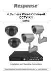
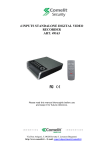
4 INPUTS STANDALONE DUPLEX DIGITAL VIDEO
RECORDER WITH DISPLAY
ART. 80153
Please read this manual thoroughly before use
and keep it for future reference.
Via Don Arrigoni, 5 24020 Rovetta S. Lorenzo (Bergamo)
http://www.comelit.it – E mail: [email protected]
Operation Manual – Art. 80153 (Version 1.1.6)
WARNING
TO REDUCE THE RISK OF FIRE OR ELECTRIC SHOCK, DO NOT EXPOSE THIS PRODUCT TO RAIN OR MOISTURE.
DO NOT INSERT ANY METALLIC OBJECT THROUGH THE VENTILATION GRILLS OR OTHER OPENINGS ON THE
EQUIPMENT.
CAUTION
Explanation of graphical symbols
The lightning flash with arrowhead symbol, within an equilateral triangle, is intended
to alert the user to the presence of uninsulated “dangerous voltage” within the
product’s enclosure that may be of sufficient magnitude to constitute a risk of
electric shock to person.
The exclamation point within an equilateral triangle is intended to alert the user to
the presence of important operating and maintenance (servicing) instructions in the
literature accompanying the product.
The user is obliged to inform himself and to conform himself to the national and local rules concerning the monitoring and the
audio and video recording. Nobody else will consequently be held responsible for an improper use of this system which
could break the laws in force.
1
Operation Manual – Art. 80153 (Version 1.1.6)
FCC COMPLIANCE STATEMENT
FCC INFORMATIONS: THIS EQUIPMENT HAS BEEN TESTED AND FOUND TO COMPLY WITH THE LIMITS FOR
CLASS A DIGITAL DEVICE, PURSUANT TO PART 15 OF THE FCC RULES. THESE LIMITS ARE DESIGNED TO
PROVIDE REASONABLE PROTECTION AGAINST HARMFUL INTERFERENCE IN A RESIDENTIAL INSTALLATION.
THIS EQUIPMENT GENERATES, USE AND CAN RADIATE RADIO FREQUENCY ENERGY AND, IF NOT ISTALLED
AND USED IN ACCORDANCE WITH THE INSTRUCTIONS, MAY CAUSE HARMFUL INTERFERENCE TO RADIO
COMMUNICATIONS. HOWEVER, THERE IS NO GUARANTEE THAT INTERFERENCE WILL NOT OCCUR IN A
PARTICULAR INSTALLATION. IF THIS EQUIPMENT DOES CAUSE HARMFUL INTERFERENCE TO RADIO OR
TELEVISION RECEPTION, THE USER IS ENCOURAGED TO CORRECT THE INTERFERENCE TO OWN EXPENSES.
CAUTION: CHANGES OR MODIFICATIONS NOT EXPRESSLY APPROVED BY THE PARTY RESPONSIBLE FOR
COMPLIANCE COULD VOID THE USER’S AUTHORITY TO OPERATE THE EQUIPMENT.
THIS CLASS A DIGITAL DEVICE COMPLIES WITH CANADIAN RULES.
CE COMPLIANCE STATEMENT
WARNING:
THIS IS A CLASS A DIGITAL DEVICE. IN A DOMESTIC ENVIRONMENT THIS PRODUCT MAY CAUSE RADIO
INTERFERENCE, IN WHICH CASE THE USER MAY BE REQUIRED TO TAKE ADEQUATE MEASURES.
2
Operation Manual – Art. 80153 (Version 1.1.6)
IMPORTANT SAFEGUARDS
1.
READ AND KEEP THESE INSTRUCTIONS
Please read this manual thoroughly before use and keep it for future reference.
2.
CLEANING
Unplug this equipment from the wall outlet before cleaning it. Use a mild household detergent, never use strong solvent. Clean the unit
with a slightly damp soft cloth.
3.
ATTACHMENTS
Never add any attachments and/or equipment without the approval of the manufacturer as such additions may result in the risk of fire,
electric shock or other personal injury.
4.
WATER AND/OR MOISTURE
Do not use this equipment near water or in contact with water.
5.
ACCESSORIES
Do not place this equipment on an instable cart, stand or table. The equipment may fall, causing serious injury to a child or adult, and
serious damage to the equipment. Wall or shelf mounting should follow the manufacturer’s instructions and shoul use a mounting kit
approved by the manufacturer. This equipment and cart combination should be moved with care. Quick stops, excessive force and uneven
surfaces may cause the equipment and cart combination to overturn.
6.
VENTILATION
If existing, the openings or ventilation grills of the device have been planned with the scope to supply ventilation to the apparatus, to
assure a reliable operation of the same and to protect it from overheating. Do not block or cover these openings.
7.
POWER SOURCES
This equipment should be operate only from the type of power source indicated on the marking label. If you are not sure of the type of
power, please consult your equipment dealer or local power company. Warning if this equipment works with battery, risk of explosion if
battery is replaced by an incorrect type. Dispose of used batteries according to the local law.
8.
GROUNDING
Do not defeat the safety purpose of the polarized or grounding-type plug. A polarized plug has two blades with one wider that the other.
A grounding type plug has two blades and a third grounding prong. The wider blade or the third prong are provided for your safety. If the
provided plug does not fit into your outlet, consult an electrician for replacement of the obsolete outlet.
9.
POWER AND CONNECTION CABLES PROTECTION
Protect the cables from being walked on or pinched particularly at plugs and the point where thy exit from the equipment.
10. LIGHTNING STORM
For added protection for this equipment during a lightning storm or when it is left unattended and unused for long periods of time, unplug
it from the wall outlet and disconnect the antenna or cable system. This will prevent damage to the equipment due to lightning and power
line surges.
11. OVERLOADING
Do not overload wall outlets and extension cords as this can result in the risk of fire or electric shock.
12. SERVICING
Do not attempt to repair this equipment yourself. The opening and the movement of the covers could you expose at high voltage or other
dangers. Refer all servicing to qualified service personnel.
13. DAMAGE REQUIRING SERVICE
Unplug this equipment from the wall outlet and refer servicing to qualified personnel under the following conditions:
a.
If the power supply cord or the plug has been damaged.
b.
If liquid is spilled or objects have fallen into the equipment.
c.
If the equipment has been exposed to rain or water.
d.
If the equipment does not operate normally by following the operating instructions. Adjust only those controls that are covered by
operating instructions. An improper adjustment of other controls may result in damage.
e.
If the equipment has been dropped or the case damaged.
f.
If the equipment exhibits a distinct change in performance.
14. REPLACEMENT PARTS
When replacement parts are required, be sure the service technician has used replacement parts specified by the manufacturer or that
have the same characteristics as the original part. Unauthorized substitutions may results in fire, electric shock or other hazards.
15. SAFETY CHECK
Upon completation of any service or repairs to this equipment, ask the service technician to perform safety checks to determine that the
equipment is in proper operating condition.
16. INSTALLATION IN PUBLIC PLACES
This kind of installation would have to be made by specialized personnel and to be in compliance with the local laws.
3
Operation Manual – Art. 80153 (Version 1.1.6)
TABLE OF CONTENTS
1. INTRODUCTION ................................................................................................................ 6
2. PHYSICAL UNIT ................................................................................................................ 6
2.1. TOP PANEL..................................................................................................................... 6
2.1.1 Function Of The Top Panel..................................................................................... 6
2.1.2 Menu Interface........................................................................................................ 6
2.2 FRONT PANEL ................................................................................................................. 8
2.3 REAR PANEL ................................................................................................................... 9
2.4 LATERAL PANEL ............................................................................................................. 10
2.5 REMOTE CONTROL (OPTIONAL)...................................................................................... 11
3. GETTING STARTED ........................................................................................................ 11
4. HARDWARE SETUP........................................................................................................ 12
4.1 IDE HARD DISK DRIVE INSTALLATION ............................................................................ 12
4.2 SATA HARD DRIVE INSTALLATION .................................................................................. 12
4.3 MONITOR CONNECTION ................................................................................................. 13
4.4 CAMERA CONNECTION .................................................................................................. 13
4.5 SENSOR CONNECTION .................................................................................................. 13
4.6 ALARM CONNECTION ..................................................................................................... 14
4.7 MOUSE CONNECTION .................................................................................................... 14
4.8 DVR POWER CONNECTION ........................................................................................... 14
5. SETUP .............................................................................................................................. 15
5.1 CAMERA ..................................................................................................................... 17
5.2 RECORD..................................................................................................................... 17
5.3 ALARM ........................................................................................................................ 19
5.4 SCREEN ..................................................................................................................... 20
5.5 AUDIO ......................................................................................................................... 21
5.6 SYSTEM...................................................................................................................... 21
5.6.1 HARD DISK SETUP............................................................................................. 22
5.6.2 ACCOUNT SETUP ............................................................................................... 23
5.6.3 PASSWORD SETUP............................................................................................ 23
5.6.4 KEYPAD TONE .................................................................................................... 24
4
Operation Manual – Art. 80153 (Version 1.1.6)
5.6.5 TIME SET ............................................................................................................. 24
5.6.6 EVENT LIST ......................................................................................................... 24
5.6.7 PTZ SETUP.......................................................................................................... 25
5.6.8 F/W UPGRADE .................................................................................................... 26
5.6.9 USB TEST ............................................................................................................ 27
5.7 LANGUAGE ................................................................................................................ 27
5.8 EXIT ............................................................................................................................ 27
6. PLAYBACK WITH TIME SEARCH FUNCTION .............................................................. 27
7. BACKUP VIA USB MEMORY STICK.............................................................................. 28
8. RECORDING LENGTH .................................................................................................... 29
9. SPECIFICATIONS ............................................................................................................ 30
10. APPENDIX...................................................................................................................... 31
10.1 SYSTEM CONNECT SKETCH MAP ................................................................................. 31
10.2 FITTING COME ALONG WITH ART. 80153...................................................................... 31
10.3 COMPATIBLE USB STICK FOR ART. 80153 (TESTED) .................................................... 31
5
Operation Manual – Art. 80153 (Version 1.1.6)
1. INTRODUCTION
Art. 80153 system provides total video security solution for 4-channel digital surveillance system supporting
duplex (simultaneous playback and record) functionality.
Either front panel buttons or remote control unit or mouse can operate all DVR menu setting.
The functionality of each button both on remote control and front panel is exactly same.
2. PHYSICAL UNIT
2.1. Top Panel
2.1.1 Function Of The Top Panel
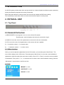
1) MENU/POWER A) long press: turn on or turn off the LCD monitor.
B) short press: used for display menu/move the cursor left or right.
2) DOWN move the cursor of the parameters on the screen sub menu downwards.
3) UP move the cursor of the parameters on the screen sub menu upwards.
4) + make the volume “+” or increase value.
5) — make the volume "—“ or reduce value.
2.1.2 Menu Interface
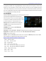
When you need to adjust the parameters for the LCD monitor, you can short press “Menu/Power”. The
menu will be display on the LCD screen. Then short press “Menu/Power” to move the cursor leftwards or
rightwards to select the option that user want to modify. Press “UP” or “Down” to move the cursor upwards
or downwards. Then, press “+” or “-“ to increase value or reduce value. After finished the setting, press the
“Menu/power” several times to confirm and exit.
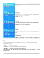
PICTURE:
“BRIGHT”: 0~100.
“CONTRAST”: 0~100.
“COLOR”: 0~100.
6
Operation Manual – Art. 80153 (Version 1.1.6)
AUDIO:
“VOLUME”: 0~100.
FUNCTION:
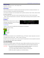
Press the button “UP” or “DOWN” to change the display mode “NORMAL & ZOOM” - of the LCD monitor.
“ZOOM”: 16:9; 4:3.
SYSTEM:
In this menu interface, users can choose the video format of display.
“S-ROLOC”: AUTO; NTSC; SECAM & PAL.
PRESET:
In this menu interface, users can close the screen automatically in two
ways.
1) Sets for the time of dormancy. The screen will be closed automatically
in stipulated time.
“SLEEP”: 0~240 minutes. The value is increased or decreased by ten.
The value of “sleep” indicates how long the LCD monitor will be turned off automatically if “OFF-TIME” is not
set.
2) Sets for closedown time and time of starting the LCD monitor. The screen closes and reveals at
corresponding time point.
“TIME”: --: --, the current time of system.
“OFF-TIME”: --: --, the time of the screen turning off automatically.
“ON-TIME”: --: --, the time of the screen turning on automatically.
When modify “TIME; OFF-TIME; ON-TIME”, press “+” to adjust the value of minute and press "—“ to adjust
the value of hour.
7
Operation Manual – Art. 80153 (Version 1.1.6)
2.2 Front Panel
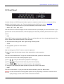
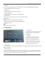
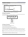
A series of button on DVR front panel make a system to operate its basic functions, such as recording,
playback, fast-forward, reverse, etc. For more details about the DVR menu, refer to “ 5. SETUP”.
** The front key panel feature can vary but the functionality of each button is same.
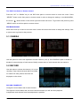
① Quad , CH1 , CH2 , CH3 , CH4
Use this button for full screen display for each camera channel or quad display on the monitor screen. If you
push “Quad” camera selection button, DVR will display all 4 channels (cameras) at the same time in quad
screen.
② REC
Press “REC” button to start manual recording. Then you will see this mark ‘●’ on the selected channel of the
screen, which means that the channel is now recording.
To stop manual recording, press “REC” again during recording mode.
③ STOP
To stop playback, press the “STOP” button.
④ PLAY
After recording, press “PLAY” button to start video playback.
Playback will start with the oldest unread video data and then continue playing.
⑤ FWD
This is the fast forward button. To play the recorded stream faster, press the “FWD” button.
There are three levels of fast forward playback speed.
(a) FF 1 (
(b) FF 2 (
(c) FF 3 (
) : Play two times faster (x2) than the normal play.
): Play three times faster (x3) than the normal play.
): Play four times faster (x4) than the normal play.
To change the fast forward play back speed level, press the “FWD” button again.
⑥ REW
This is the rewind button. To play the recorded stream backward, press the “REW” button.
[NOTE]: The fast forward and reverse playback speeds will vary depending on the frame rate and record
quality settings, as well as the number of channels recorded.
8
Operation Manual – Art. 80153 (Version 1.1.6)
⑦ PAUSE
To pause the video playback, press the “PAUSE” button. Then the video displaying will be stopped.
To continue playback, push the “PLAY” button.
⑧ MENU/ESC
It displays menu option or go back to the previous.
⑨ UP(▲) / DOWN(▼)
To change a menu field, use the “UP” or “DOWN” buttons.
⑩ SELECT/EDIT
Use this button to change values on main menu or sub menu setting.
LED Light
(a) GREEN: The DVR unit is powered up and running.
(b) RED: System is in Recording Mode or in Playback Mode.
(c) IR Remote Receiver
PTZ
Use this button to enter PTZ mode.
2.3 Rear Panel
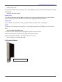
① AUDIO OUT
Use “AUDIO OUT” port for speaker (mono)
connecting, this port is audio output for
playback too.
② AUDIO IN
Use “AUDIO IN” port for microphone
connection. If signal audio input is from
channel 1, there will be audio output in
channel 1 view and quad view. If signal
audio input is from channel 2, there won’t
be audio output until in channel 2.
③ VIDEO INPUT
Use this BNC port to connect cameras to DVR system. You might need BNC connector for each (CH1-CH4)
camera connection.
④ VIDEO OUTPUT
Use this port to connect DVR to the monitor. There is one video output. You can also connect one monitor
at the same time which will display the same video image on both monitor and LCD monitor. Also, you can
use the video output port to connect VHS device for tape backup.
9
Operation Manual – Art. 80153 (Version 1.1.6)
⑤ PS/2 MOUSE PORT
Use this port for PS/2 mouse connection. If you have USB port mouse, use USB - PS/2 adapter to connect
with this port.
⑥ SENSOR / ALARM / RS485
Sensor input
You can use this sensor terminal block to install up to 4 motion sensors into DVR. If you add the motion
sensor devices to your DVR, the video recording can be triggered by motion detection.
Alarm input
This is an alarm input terminal in case you need to attach an alarm device on the system.
RS485
The two ports are RS485 power line ports. To control high-speed dome only RS485 line is connected to
DVR.
⑦ AC-DC POWER ADAPTER JACK
Connect the power adapter into DVR and plug the power cord into the wall.
Below is the information of input/output voltage for the power adapter.
[Input: AC 100-240V, 50/60Hz, 1.5A / Output: DC +12V == 3A]
⑧ THE POSITION OF INSTALLING HDD
2.4 Lateral Panel
USB Port (For Backup)
10
Operation Manual – Art. 80153 (Version 1.1.6)
2.5 Remote Control (optional)
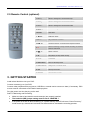
1. CH1 ↑
Select or enlarge CH1 or Move dome up
2. CH2 ↓
Select or enlarge CH2 or Move dome down
3. CH3 ←
Select or enlarge CH3 or Move dome left
4. CH4 →
Select or enlarge CH4 or Move dome right
5.QUAD
Quad View
6. ◄◄ Z-
Rewind or Zoom-
7. ► F+
Play record list or Focus+
8. ►► Z+
Forward or Zoom+ or Channel auto sequence switch
9. ●
Manual recording or Stop manual recording or Reduce
10. ▌▌ F-
Pause or Focus-
11. ■
Stop playing or Stop dome running
12. PTZ
PTZ Switch
13.Menu/ESC
Enter or exit setup menu
14.Select/Enter
Modify item or Increase value
15.UP
Move up the cursor
16.DOWN
Move down the cursor
value or Level scan
3. GETTING STARTED
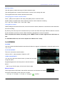
Install a hard disk drive into your DVR.
Connect cameras (up to 4) to DVR.
Connect other peripheral devices (mouse, USB Drive, external motion sensors or alarm) if necessary. PS/2
mouse must be connected to DVR before startup system.
Plug the power cord into the plug on the wall.
Start TV Monitoring and Recording.
Make sure that a hard disk drive and camera(s) are properly installed.
The hard disk (IDE) jumper setting must be set to “MASTER “!.
If the power is turned off while recording (i.e. a power failure), the DVR will enter “Power Recovery”
mode at start up, detect that it has been shut down and then reinitiate the recording process.
11
Operation Manual – Art. 80153 (Version 1.1.6)
4. HARDWARE SETUP
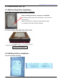
4.1 IDE Hard Disk Drive Installation
NOTE: Make sure that HDD jumper setting as “MASTER”
Before installing hard drive, set jumper as “MASTER”.
The master jumper setting varies depending on the hard drive
manufactures.
Refer to manufacture’s manual for master jumper setting.
For example, this model of HDD is Seagate.
Connect the ribbon cable (IDE) cable & power cable
Back side of hard disk
4.2 SATA Hard Drive Installation
Connect the cables as follows.
12
Operation Manual – Art. 80153 (Version 1.1.6)
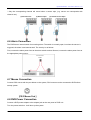
4.3 Monitor Connection
To display video image from cameras on the monitor, the DVR’s video output signal should be transferred
to your TV set or monitor.
Connect a monitor at “VIDEO
OUT” ports on DVR
“VIDEO IN” port on MONITOR
“VIDEO OUT” port on DVR
Connect “VIDEO IN” of the monitor to “VIDEO OUT” of the DVR system.
4.4 Camera Connection
Connect between “VIDEO IN” of your DVR and “VIDEO OUT” of camera with video cable and plug in the
camera’s power adapter.
“VIDEO OUT” on CAMERA
“VIDEO IN” on DVR
4.5 Sensor Connection
Our 4 CH DVR system can connect up to four sensors.
There are two steps for sensor installation.
(a) Connect the sensor signal lines to the signal input terminal.
(b) Connect the sensor power lines to the appropriate power source.
In general, there are three different types of sensors available in the home electrics store, where you can
buy them. (1) Normal-Close. (2) Normal-Open. (3) Normal-Close & Open. Below is the brief diagram
about how the each type of sensor is installed into DVR. The procedure for sensor install action is as shown
below.
* After you install sensor(s), change the recording mode as “Sensor record” or “MD & Sensor record” on
“RECORD SCHEDULE” in the DVR menu to enable sensor recording.
13
Operation Manual – Art. 80153 (Version 1.1.6)
* Only the corresponding channel will record when a sensor trips, (e.g. sensor one corresponds with
channel one).
(1) Normal-Close
(2) Normal-Open
(3) Normal Close & Open
4.6 Alarm Connection
The DVR has an internal switch for sounding alarm. The switch is normally open, but when the sensor is
triggered, the alarm is activated as well. The circuitry is as follows.
First, connect the alarm power lines to the alarm switch terminal. Second, connect the alarm power lines to
the appropriate power source.
DVR Rear Panel
ALARM
4.7 Mouse Connection
Connect PS/2 mouse with the port below on the system, PS/2 mouse must be connected to DVR before
startup system.
4.8 DVR Power Connection
Connect a DVR power adapter to the adapter jack at the rear panel of DVR unit.
Turn the power switch on. It will boot up the system.
14
Operation Manual – Art. 80153 (Version 1.1.6)
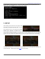
If users install a new hard disk drive, it will ask for HDD formatting before a system starts to run
(Below Fig). Choose FORMAT option pressing “PLAY” button.
5. SETUP
After installing a new hard drive on the system, user
had better to format the hard drive first. There are
three password levels in the system that including
Admin (highest), Operator, and Guest (lowest). If
the user does not login the system, he can only view live video display and when the user login the
system, if he don’t operate the system in thirty seconds, the system will be locked automatically.
The system allows up to four user accounts. The administrator can set up the login name, password and
level for each user. (Please refer to Section 5.6.2 for Account Setup.)
15
Operation Manual – Art. 80153 (Version 1.1.6)
The Admin can operate everything, the Operator can operate everything except examining user accounts
and modifying its password level and the Guest can operate live video display and image playback.
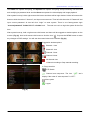
After system boot-up, hold a right mouse click button and there will be login window. Hold a left mouse click
button to click the order of “Account”, and input correct account. Then left click the order of “Password” and
input correct password. At last left click “Login” to enter system. There is one factory-preset login
“account/password” “Admin/111111” at Admin level. The user can use it to login the system for the first
time.
After system boot-up, hold a right mouse click button and there will be suggestive window options on the
monitor (Fig (a)). Hold a left mouse click button to click the icon “ ”. Or press the MENU button to make
any changes of DVR settings. You will see the screen below on the monitor (Fig (b)).
Suggestive window options:
Channel 1 view
Channel 2 view
Channel 3 view
Channel 4 view
All channel view
● Manual recording or Stop manual recording
Fig (a)
► Play record list
PTZ Switch
Channel auto sequence. The icon “
display if the order of “auto sequence” is “OFF”.
Menu option
Logout
Fig (b)
16
” won’t
Operation Manual – Art. 80153 (Version 1.1.6)
The DVR Front Panel or Remote Control
Press the “UP” or “DOWN” key on the DVR front panel or remote control to move the cursor. Press
“SELECT” button on the front panel or remote control in order to change the settings. In the MAIN MENU,
the cursor “
” will be shown on the screen right next to each sub menu. To go back to the previous, press
“MENU” button on the front panel or remote control.
The Mouse Control
Move the mouse up or down to move the cursor. Hold a left mouse click button to change the settings. Click
a right mouse to go back to the previous.
5.1 CAMERA
Use this option for video color adjustment for each channel (1,2,3,4). Go to DISPLAY option to enable or
disable for screen display of each camera. Modify camera name of each channel that user wants to.
5.2 RECORD
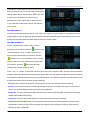
Use this option to choose the channel (1,2,3,4) for
recording. Only selected channel will be recorded
no matter how many camera channels are
displayed on the screen.
RECORD FRAMERATE
Change the record frame rate for each channel.
The higher the record frame rate, the more natural movement you will see while playback.
Independent each channel frame rate adjustment is possible.
17
Operation Manual – Art. 80153 (Version 1.1.6)
Press button 【ENTER】or hold a left mouse click
button to click icon “►” to increase the record frame
rate for each channel. Press button 【REC】or hold
a left mouse click button to click icon “◄” to
decrease the record frame rate for each channel.
If you make the record frame rate off, the channel
won’t record.
RECORD QUALITY
Choose record quality among Normal / Low / High. The higher the record quality is, the higher the video
image quality is well you playback. Higher quality cost more hard disk space. Record frame rate, record
quality and hard disk space will affect total record time of DVR system.
RECORD SCHEDULE
Notice: To start motion record, make sure the
period that you intend to record is “ ” (green) in the
“record schedule” menu. To start sensor record,
make sure the period that you intend to record is
“ ” (yellow) in the “record schedule” menu. To start
motion & sensor record, make sure the period that
you intend to record is “ ” (half green and half
yellow) in the “record schedule” menu.
Press 「Up」 or 「Down」or move the mouse to move the cursor and press「SEL」or hold a left mouse button
to adjust video record method during each time period. Also user can adjust the same record method during
the whole time periods synchronously, press [QUAD] button in the DVR front panel or remote control or hold
a left mouse button to click the time period (24:00:00).
- Grey bar: No record will be made for this time period if user don’t activate manual recording.
- Red bar: The time period with a red bar will activate continuous recording mode (Time record) unless
there is any manual stopping during recording during that time.
- Green bar: The time period with a green bar for built-in motion recording (MD). (See also the following
chapter “MOTION DETECTION”)
- Yellow bar: The time period with yellow bar will activate external sensor recording.
- Half-yellow and half-green bar: The time period with half-yellow and half-green bar will activate the
combination of built-in motion (MD) recording and external sensor (Sensor) recording. (See also the
following chapter “SENSOR”)
18
Operation Manual – Art. 80153 (Version 1.1.6)
5.3 ALARM
Using SELECT button or hold a left mouse button to click icon
“◄” / “►” adjust parameters of each option.
ALARM DURATION
It sets the alarm duration time (in seconds) after alarm is
activated.
Value at “05, 10, 15, 20, 25, 30, CONT, OFF”(in seconds).
Default is “OFF”.
By changing the value in the ALARM DURATION, you can
adjust how long the alarm will last in seconds. The alarm device should be installed.
BUZZER DURATION
It sets the buzzer duration time (in seconds) after alarm is activated.
Value at “05, 10, 15, 20, 25, 30, CONT, OFF” (in seconds). Default is “OFF”. When “buzzer duration” is
“cont”, the buzzer will work continuously.
EVENT REC DURATION
It sets the record time of duration (in seconds) after sensor recording or motion recording or MD & sensor
recording is activated.
Value at “05, 10, 15, 20, 25, 30” (in seconds).
SENSOR
Activate / deactivate or choose the type of sensor. There are
three
different
modes
for
sensor
setting:
N.C
(NORMAL-CLOSE) & N.O (NORMAL-OPEN) & NONE.
Select “None” to deactivate sensor recording or if there was
no sensor installed in DVR system.
Chose the type of sensor (N.O or N.C) installed in DVR.
MOTION DETECTION
CHANNEL
Select the channel (1,2,3,4) for recording mode by internal
motion.
SENSITIVITY
It adjusts the sensitivity of the built-in motion sensor on the
DVR system while recording. The higher the number, the
higher the sensitivity is. Value at “1, 2, 3, 4, Off”. The
maximum sensitivity level is 4.
19
Operation Manual – Art. 80153 (Version 1.1.6)
MOTION AREA
Use this option to select the range of motion detection area.
Use the keypad button, remote control button or mouse click to assign the area.
The keypad and mouse control instructions are below.
Using keypad or remote control button
Press [SEL] once to pitch on the area, press [SEL] twice to cancel the area.
QUAD: Select or deselect the motion detection area for motion detection recording.
CH1 - Up / CH2 - Down / CH3 - Left / CH4 - Right
Using Mouse button
While holding a left mouse click button, move the mouse to select, deselect or reselect the motion detection
area for recording.
By the way, the area only can be selected from up to down and from left to right. When the block is covered
by blue shadow it’s active to record. When the block is transparent it can’t be recorded.
After completed the motion area setting, press “MENU” button or hold a right mouse click button to
exit.
To start Motion Record, user must complete the “Motion area” setup.
5.4 SCREEN
BORDER
User can make the white borderline around each channel to appear or disappear by using this option to be
“on” or “off”.
AUTO SEQUENCE
This is for auto screen switch rotation.
Value at “Off, 1~10(in seconds)”. Default is “Off”.
VIDEO ADJUSTMENT
You can move the entire video screen up, down, left, and right
using this option.
Keypad assignment in the front panel or remote control is
below.
-CH1 for up, CH2 for down, CH3 for left, CH4 for right.
Mouse function:
Hold a right mouse click button, there will be some icons on the screen as follows “
left mouse click button to click each icon to select.
-“▲”for up, “▼” for down, “◄” for left, “►” for right, “
20
” for ESC.
”. Hold a
Operation Manual – Art. 80153 (Version 1.1.6)
5.5 AUDIO
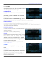
Make the record “ON” to enable sound recording
when a microphone device is attached in AUDIO
INPUT port on the system.
Adjust volume for speaker and the intensity level of
sound recording. To make the sound enabled for
speaker, leave the mute “OFF”.
5.6 SYSTEM
Fig (c)
Fig (d)
In this menu, you can see the information of the hard disk drive installed on the system, change the system
password, adjust keypad tone, browser event list or adjust current time on the system.
If user login the system at Admin level, the menu bar will be displayed as Fig (c). The user can enter into
the order of “Account” to examine all user accounts, add or delete user that he wants to (Please refer to
section 5.6.2 for account setup).
If user login the system at Operator or Guest level, the menu bar will be displayed as Fig (d). The user can
only modify its own password. (Please refer to 5.6.3 for password setup)
21
Operation Manual – Art. 80153 (Version 1.1.6)
5.6.1 HARD DISK SETUP
OVERWRITE ENABLED
If you choose YES, recording continues and overwrites
previous recording when hard disk drive space is full. If you
choose NO, the recording stops when the hard disk drive is
full.
FORMAT HDD
If you format the hard disk drive, all the video data
stored on the hard disk drive will be deleted!
Remind that the system has no restore option once the
hard drive is formatted.
When you choose this option, it will ask for password before formatting. The default password is “111111”.
Type the password and press any key button.
When HDD is successfully formatted, you will see the message below blinking.
If the password is incorrect, you will see the below message blinking. Then try to type right password again.
22
Operation Manual – Art. 80153 (Version 1.1.6)
5.6.2 ACCOUNT SETUP
Only if the user log in the system at Admin level, the
Account Setup allows the administrator to add new users,
delete existing ones and modify the user’s name / password
/ level.
The system allows up to 4 user accounts.
[Account]/[Password]
In setup Menu display, move the cursor to change the
highlighted option to Account and then press ENTER to call
up Account/Password as shown. All numbers, letters and sign
in the panel can be used as user account or password. Press
「SEL」to input value and move the cursor to the option of
“ENTER”, press 「SEL」to confirm.
CH1 for up, CH2 for down, CH3 for left, CH4 for right, Press
“Shift” for change characters.
[Level]
Move the cursor to change the highlighted option to Level and
then press [SEL] to adjust user level (Operator/Guest).
5.6.3 PASSWORD SETUP
The default password is 111111. All numbers, letters and
sign in the panel can be used as password. Press 「SEL」
to input value and move the cursor to the option of “ENTER”,
press 「SEL」to input current password.
CH1 for up, CH2 for down, CH3 for left, CH4 for right.
The same operation measure to input new password and
confirm password.
23
Operation Manual – Art. 80153 (Version 1.1.6)
When password change succeed, user will see the below message blowing.
When password change fail, user will see the below message blowing.
5.6.4 KEYPAD TONE
Make the keypad tone “ON” or “OFF” to enable or disable keypad tone during operating.
5.6.5 TIME SET
You can adjust the current time, date and year at any time
by region. Set your region first and set the current time so
that the video back-up data can be played without time
shifting later on.
Date and Time format are below.
*** 2008/08/08 - year/month/day
*** 01:01:00 - hour: minute: second
To move the cursor on the screen, use “UP” and “DOWN” key on the DVR front panel or remote control and
then press “SELECT” button to change the numeric value. Once you finish time setting, press “MENU”
button. Then press “DOWN” key and “SELECT” button to apply the new time set or move the mouse to
move the cursor up and down, hold a left mouse click button to change the numeric value. Once you finish
time setting, hold a right mouse click button to return. Then move the mouse to the order of “Apply” to left
click to apply the new time set.
5.6.6 EVENT LIST
EVENT LIST function enables playback by event.
On the Event List menu, it shows all past recorded
video, start time and end time of each recorded
video and showing recording year / date / time. The
HDD can be store 300 pieces of event in it at most.
If the events are over 300 pieces, user can play
previous event according to input time period if the
data hasn’t been over-written.
24
Operation Manual – Art. 80153 (Version 1.1.6)
To playback by EVENT LIST, using [UP]/[DOWN] or channel number (CH1 for Page Up or CH2 for Page
Down) key on the front panel or remote control, select the event that you want to playback and press
“PLAY” button. Another way is to move the mouse up and down or click the left mouse button (“◄” for Page
Up or “►” for Page Down), select the event that you want to playback and double click the left mouse button.
Then it wills playback the recording video data.
5.6.7 PTZ SETUP
Adjust the RS485 setting depending on the PTZ camera that you have.
Our DVR system supports PELCO-D protocol and
PELCO-P protocol. Then we can see the diagram that is
on the right. For example, we select the channel 1 to set
up. Dome’s address is 1. Protocol makes use of
PELCO-D. Baud rate is 4800 and Dome’s speed is 7.
CHANNEL: Select a camera channel where PTZ
camera is connected.
ADDRESS: Dome’s address “0-255” (PELCO-D)
and”0-31” (PELCO-P).
PROTOCOL: Including “PELCO-D”, “PELCO-P”. Setting the protocol according to the dome’s protocol.
BAUD RATE: Press “SEL” button to select the value 1200, 2400, 4800, 9600, 19200 bps.
SPEED: Having “1-10” to select.
PRESET: If protocol is PELCO-D, preset includes “1-31”. If protocol is PELCO-P, preset includes “1-255”.
When it displays 0, it suggests that the place’s preset is not using.
Button function On The Front Panel or Remote Control:
「Select」: Make the setting.
「Up」「Down」: Move the cursor.
「SEL」: Increase Value.
「REC」: Reduce Value or Auto-scan.
「Ch1」
「Ch2」: Move the dome upwards and downwards.
「Ch3」
「Ch4」: Move the dome leftwards and rightwards.
「STOP」: Stop the dome running.
「REW」
「FWD」: Zoom.
「Pause」「Play」: Focus.
25
Operation Manual – Art. 80153 (Version 1.1.6)
Mouse function:
Left Mouse: Click the icon “►” or “◄” to adjust value.
Right Mouse: Previous.
Preset setup:
User must set preset at first. The address, protocol and baud rate of DVR is consistent with Dome’s. You
can make use buttons to control dome and save the preset.
If user wants to call preset, user can modify the value of preset to come true. Press「Select」button to finish
the order of “call preset”.
User can perform auto scan when he saves the presets within cruise locus. Then he needs to press
「Select」button to finish the order of “auto scan”, the dome will run all along unless user presses「STOP」
button to stop it.
PTZ Mode:
Enter into PTZ mode and hold a right mouse
click button, there will be a piece of message
on the screen (right figure).
Icon function:
“▲▼►◄”: Move the dome upwards/downwards\leftwards and rightwards.
“■”: Stop the dome running.
“
、
”: Focus.
“
、
”: Zoom.
“
”: Auto scan.
“
”: Previous.
Attention:
User can start-up automatic scout in “PTZ SETUP” menu or PTZ mode. It doesn’t stop when user exits. If
user wants to stop scouting, press 「STOP」button in PTZ mode.
During live view, user can press「PTZ」button to enter PTZ mode and then user can operate to control the
dome according to the method of above paragraphs.
5.6.8 F/W UPGRADE
This menu is for firmware upgrade of DVR system through USB host (USB memory stick) connection, you
can simply upgrade the system once you connect the USB memory stick that contains a firmware file.
CAUTION:
1. Do not turn off the system while the system is upgrading. Otherwise, it will cause the
breakdown of the system that needs a special recovery process.
2. If you don’t install a HDD in the DVR, the system can’t be upgrade.
3. Before the system is upgrade, you must stop recording.
26
Operation Manual – Art. 80153 (Version 1.1.6)
5.6.9 USB TEST
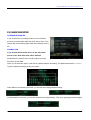
This option is testing purpose only. Users can check the
compatibility of the USB memory stick for backup.
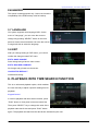
5.7 LANGUAGE
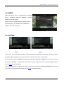
Our system supports multi-language OSD. On the
menu of “Language”, you can move the cursor to
change it by pushing “SELECT” button on the front
panel or remote control and also can move the mouse
to single left-click to select the language.
5.8 EXIT
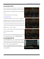
After you change setting on DVR menu, you need to
confirm the changes under EXIT menu.
EXIT & SAVE CHANGE
Save change and go back to main screen.
EXIT & DISCARD CHANGES
No change and go back to main screen.
LOAD SETUP DEFAULT
Load default setting.
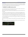
6. PLAYBACK WITH TIME SEARCH FUNCTION
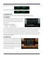
This is an enhanced playback option, which enables
the user manually to adjust a specific starting time for
playback.
Keypad Control:
In order to playback with time search function, press
"PLAY” button on front panel or remote control first.
Then press “SELECT” key to change the value of the
playback start date & time and press “PLAY” button
again. The playback will start from the date & time indicated by the user.
27
Operation Manual – Art. 80153 (Version 1.1.6)
Mouse Control:
Hold a right mouse click button and left click the icon “►”. Then press the left mouse button to change the
value of the playback start date & time and press the right mouse button. Then hold a left mouse button to
click “Search”, the playback will start from the date & time indicated by the user.
7. BACKUP via USB memory stick
Our 4-channel DVR system has an enhanced back-up features so that it’s possible to transfer the video
data image recorded on the hard drive to USB memory stick drive.
Before you back up a stream of video data, have the USB memory stick to be ready and attach them into
DVR system.
In order to save the video data with these back-up devices, you should first start with playback and then
press “MENU” button. Use “UP” key or “DOWN” key move the cursor, then press “SELECT” button to set
start time and the end time of the recorded video data which will be saved on back-up devices. If you want
to setup the end time faster, you can press the button [►►FWD] to change the play speed that you want
and then press [DOWN] to select end time again. After setting the time of backup, you should press [PLAY]
to recover the normal speed.
Move the cursor to the option “USB copy”, then press “SELECT” button to backup the video data on USB
stick.
After playback, press “MENU” button. Then using “UP” and “DOWN” key set the time period of recorded
video data that you want to save on the back-up devices.
28
Operation Manual – Art. 80153 (Version 1.1.6)
USB copy:
Move the cursor to “USB copy” and press “SELECT” button or hold a left mouse click button to back up a
stream of video data on USB memory stick.
It will take a few minutes to write the video data on USB memory stick. The file size number is going up until
it’s done with the message below.
WRITING…
Then it will show the following message on the screen.
FIXATING…
Take out the USB memory stick and attach it into your
PC when it’s done.
Press “PLAY” button to continue with a system.
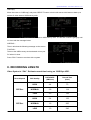
8. RECORDING LENGTH
Video System is “PAL”. Estimate record time basing on 320G Byte HDD.
Record Speed
50F/Sec
25F/Sec
REC Quality
DATA RATE
(GB/Hour)
Record Time
(Hour)
HIGH
4.4
73
NORMAL
2.8
114
LOW
2.3
139
HIGH
2.4
133
NORMAL
1.6
200
LOW
1.3
246
29
Operation Manual – Art. 80153 (Version 1.1.6)
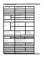
9. SPECIFICATIONS
ITEM
DESCRIPTION
Video Format
NTSC / PAL
Operation System
None
Camera Input Channel
4 channel Composite BNC
Video Output Channel
1 channel Composite BNC
Recording
Frame
Rate
NTSC
Max 60 fps (Total)
PAL
Max.50 fps (Total)
NOTE
STAND-ALONE
Max. 30 frames/s
(Each Channel)
Max. 25 frames/s
(Each Channel)
Time schedule, Motion detection, Sensor activated, Motion
Record Mode
detection & Sensor activated
NTSC:720 x 480
Display
PAL:720 x 576
Resolution
NTSC:320 x 112; 640 x 224
Recording
PAL:320 x 136; 640 x 272
Video Quality:
Compression Method
Enhanced MJPEG
Low @ 12K Bytes;
(12-20K Bytes/frame)
Normal @ 15K Bytes;
High @ 20K Bytes
HDD Support
Search
Over 500G Byte
Method
Time, Event
Full Screen
YES
SATA or IDE ATA –100 Interface HDD×1
4 Input (Normal Open / Normal Close)
Sensor, Alarm
1 Output (Alarm) (12 Pin DIP Switch)
Camera Signal Loss Alarm
2 Pin for RS485 control Pan/Tilt/Zoom
PTZ(RS485)
YES
PELCO-D, PELCO-P
Audio Input
2 Channels Composite RCA
Audio Output
1 Channel Composite RCA
USB
YES
38KHZ Remote Control Unit
Optional
PS/2 Mouse
Optional
Power Input
100-240VAC/DC 12V , 3A(Adapter supplying)
Dimension (L x W x H)
300 x 70 x 290 mm
USB 2.0 for media Backup
30
Operation Manual – Art. 80153 (Version 1.1.6)
10. APPENDIX
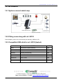
10.1 System connect sketch map
10.2 Fitting come along with art. 80153
Power adapter, power cord, user manual (this manual), USB drive CD.
10.3 Compatible USB stick for art. 80153 (tested).
COMPANY
MODEL
SIZE
SONY
MICROVAULT (SOK-USM1GJ)
1GB
SAMSUNG
SUM-LCB1
1GB
TRANSCEND
JF V30
2GB
APACER
Weblink (SYE5003358)
2GB
SANDISK
CRUZER micro
4GB
FLEX
FD-02
1GB
KINGSTON
Data Traveler
2GB
KINGSTON
Data Traveler
1GB
LEMON
LEMON USB Drive
1GB
Via Don Arrigoni, 5 24020 Rovetta S. Lorenzo (Bergamo)
http://www.comelit.it – E mail: [email protected]
31