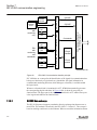
1
Relion® Protection and Control
650 series ANSI
Engineering Manual
Document ID: 1MRK 511 261-UUS
Issued: June 2012
Revision: A
Product version: 1.2
© Copyright 2012 ABB. All rights reserved
Copyright
This document and parts thereof must not be reproduced or copied without written
permission from ABB, and the contents thereof must not be imparted to a third party,
nor used for any unauthorized purpose.
The software and hardware described in this document is furnished under a license and
may be used or disclosed only in accordance with the terms of such license.
Trademarks
ABB and Relion are registered trademarks of the ABB Group. All other brand or
product names mentioned in this document may be trademarks or registered
trademarks of their respective holders.
Warranty
Please inquire about the terms of warranty from your nearest ABB representative.
ABB Inc.
1021 Main Campus Drive
Raleigh, NC 27606, USA
Toll Free: 1-800-HELP-365, menu option #8
ABB Inc.
3450 Harvester Road
Burlington, ON L7N 3W5, Canada
Toll Free: 1-800-HELP-365, menu option #8
ABB Mexico S.A. de C.V.
Paseo de las Americas No. 31 Lomas Verdes 3a secc.
53125, Naucalpan, Estado De Mexico, MEXICO
Phone: (+1) 440-585-7804, menu option #8
Disclaimer
The data, examples and diagrams in this manual are included solely for the concept or
product description and are not to be deemed as a statement of guaranteed properties.
All persons responsible for applying the equipment addressed in this manual must
satisfy themselves that each intended application is suitable and acceptable, including
that any applicable safety or other operational requirements are complied with. In
particular, any risks in applications where a system failure and/or product failure would
create a risk for harm to property or persons (including but not limited to personal
injuries or death) shall be the sole responsibility of the person or entity applying the
equipment, and those so responsible are hereby requested to ensure that all measures
are taken to exclude or mitigate such risks.
This document has been carefully checked by ABB but deviations cannot be
completely ruled out. In case any errors are detected, the reader is kindly requested to
notify the manufacturer. Other than under explicit contractual commitments, in no
event shall ABB be responsible or liable for any loss or damage resulting from the use
of this manual or the application of the equipment.
Conformity
This product complies with the directive of the Council of the European Communities
on the approximation of the laws of the Member States relating to electromagnetic
compatibility (EMC Directive 2004/108/EC) and concerning electrical equipment for
use within specified voltage limits (Low-voltage directive 2006/95/EC). This
conformity is the result of tests conducted by ABB in accordance with the product
standards EN 50263 and EN 60255-26 for the EMC directive, and with the product
standards EN 60255-1 and EN 60255-27 for the low voltage directive. The product is
designed in accordance with the international standards of the IEC 60255 series and
ANSI C37.90. The DNP protocol implementation in the IED conforms to "DNP3
Intelligent Electronic Device (IED) Certification Procedure Subset Level 2", available
at www.dnp.org .
Table of contents
Table of contents
Section 1
Introduction............................................................................5
This manual..............................................................................................5
Intended audience....................................................................................5
Product documentation.............................................................................6
Product documentation set..................................................................6
Document revision history...................................................................7
Related documents..............................................................................8
Symbols and conventions.........................................................................8
Symbols...............................................................................................8
Document conventions........................................................................9
Functions included in 650 series IEDs................................................9
Section 2
Engineering tool set.............................................................17
Introduction.............................................................................................17
IED engineering process........................................................................19
Section 3
Engineering process............................................................23
Workflow.................................................................................................23
Section 4
Setting up a project.............................................................27
PCM600 operates on projects................................................................27
Installing Connectivity packages.............................................................27
Setting technical key...............................................................................28
Setting up communication between PCM600 and the IED.....................31
Project managing in PCM600.................................................................36
Building a plant structure........................................................................38
IEC 61850 naming conventions to identify an IED............................39
Inserting an IED......................................................................................41
Setting IED IP address in the project.................................................53
Section 5
Protection and control engineering......................................57
Creating an application configuration with ACT......................................57
Overview............................................................................................57
Function blocks..................................................................................58
Signals and signal management.......................................................60
Function block execution parameters................................................61
Configuration parameters..................................................................64
650 series ANSI
Engineering Manual
1
Table of contents
Connections and variables................................................................64
Hardware channels............................................................................65
Validation...........................................................................................66
Setting configuration and setting parameters in PST.............................68
Connecting signals in SMT.....................................................................69
Section 6
Local HMI engineering........................................................73
LED and function key engineering..........................................................73
Local HMI engineering process.........................................................73
LED operation modes........................................................................78
Single-line diagram engineering.............................................................84
Concept description to present and generate diagrams in
graphical display editor......................................................................84
Supported single-line diagram symbols.............................................89
Bay configuration engineering...........................................................92
Events and indications............................................................................97
Section 7
IEC 61850 communication engineering..............................99
IEC 61850 interface in the IED and tools................................................99
Function view for IEC 61850 in PCM600...........................................99
IEC 61850 interface in IED................................................................99
GOOSE data exchange..............................................................100
Station configuration description file types......................................101
IEC 61850 engineering procedure........................................................102
IEC 61850 protocol references and pre-conditions.........................102
Sequence for engineering of IEC 61850 protocol............................102
Exporting SCL files from PCM600........................................................104
Exporting SCD files.........................................................................104
Exporting ICD or CID files................................................................105
Engineering of vertical and horizontal communication in IET600.........106
Importing SCL files to PCM600............................................................107
Importing SCD files..........................................................................108
Importing ICD or CID files................................................................110
Writing communication configuration to IED ........................................111
Section 8
IEC 60870-5-103 communication engineering..................113
Engineering in PCM600........................................................................113
Selecting to communicate IEC60870-5-103 data via RS485
serial interface on COM05 module.............................................113
Selecting to communicate IEC60870-5-103 data via optical
serial interface on COM05 module.............................................114
2
650 series ANSI
Engineering Manual
Table of contents
Section 9
DNP3 communication engineering....................................115
Signal configuration user information...................................................115
Adding setting groups...........................................................................116
Configuring DNP3 protocol signals.......................................................118
Setting DNP3 signal parameters..........................................................121
Configuring DNP3 class..................................................................122
Selecting to communicate DNP3 data via RS485 serial
interface on COM05 module............................................................123
RS485 specific parameters........................................................123
Selecting to communicate DNP3 data via optical serial
interface on COM05 module............................................................123
Section 10 Glossary............................................................................125
650 series ANSI
Engineering Manual
3
4
Section 1
Introduction
1MRK 511 261-UUS A
Section 1
Introduction
1.1
This manual
The engineering manual contains instructions on how to engineer the IEDs using the
different tools in PCM600. The manual provides instructions on how to set up a
PCM600 project and insert IEDs to the project structure. The manual also recommends
a sequence for engineering of protection and control functions, LHMI functions as well
as communication engineering for IEC 60870-5-103, IEC 61850 and DNP3.
1.2
Intended audience
This manual addresses system and project engineers involved in the engineering
process of a project, and installation and commissioning personnel, who use technical
data during engineering, installation and commissioning, and in normal service.
The system engineer must have a thorough knowledge of protection and/or control
systems, protection and/or control equipment, protection and/or control functions and
the configured functional logics in the IEDs. The installation and commissioning
personnel must have a basic knowledge of handling electronic equipment.
650 series ANSI
Engineering Manual
5
Section 1
Introduction
Decommissioning
deinstalling & disposal
Maintenance
Operation
Product documentation set
Commissioning
1.3.1
Installing
Product documentation
Planning & purchase
1.3
Engineering
1MRK 511 261-UUS A
Engineering manual
Installation manual
Commissioning manual
Operation manual
Service manual
Application manual
Technical manual
Communication protocol
manual
en07000220.vsd
IEC07000220 V1 EN
Figure 1:
The intended use of manuals in different lifecycles
The engineering manual contains instructions on how to engineer the IEDs using the
different tools in PCM600. The manual provides instructions on how to set up a
PCM600 project and insert IEDs to the project structure. The manual also recommends
a sequence for engineering of protection and control functions, LHMI functions as well
as communication engineering for IEC 60870-5-103, IEC 61850 and DNP3.
The installation manual contains instructions on how to install the IED. The manual
provides procedures for mechanical and electrical installation. The chapters are
organized in chronological order in which the IED should be installed.
The commissioning manual contains instructions on how to commission the IED. The
manual can also be used by system engineers and maintenance personnel for assistance
6
650 series ANSI
Engineering Manual
Section 1
Introduction
1MRK 511 261-UUS A
during the testing phase. The manual provides procedures for checking of external
circuitry and energizing the IED, parameter setting and configuration as well as
verifying settings by secondary injection. The manual describes the process of testing
an IED in a substation which is not in service. The chapters are organized in
chronological order in which the IED should be commissioned.
The operation manual contains instructions on how to operate the IED once it has been
commissioned. The manual provides instructions for monitoring, controlling and
setting the IED. The manual also describes how to identify disturbances and how to
view calculated and measured power grid data to determine the cause of a fault.
The service manual contains instructions on how to service and maintain the IED. The
manual also provides procedures for de-energizing, de-commissioning and disposal of
the IED.
The application manual contains application descriptions and setting guidelines sorted
per function. The manual can be used to find out when and for what purpose a typical
protection function can be used. The manual can also be used when calculating settings.
The technical manual contains application and functionality descriptions and lists
function blocks, logic diagrams, input and output signals, setting parameters and
technical data sorted per function. The manual can be used as a technical reference
during the engineering phase, installation and commissioning phase, and during normal
service.
The communication protocol manual describes a communication protocol supported by
the IED. The manual concentrates on vendor-specific implementations.
The point list manual describes the outlook and properties of the data points specific to
the IED. The manual should be used in conjunction with the corresponding
communication protocol manual.
1.3.2
Document revision history
Document revision/date
650 series ANSI
Engineering Manual
History
-/March 2012
First release
A/June 2012
Minor corrections made
7
Section 1
Introduction
1.3.3
1MRK 511 261-UUS A
Related documents
650 series manuals
Identity number
Communication protocol manual, DNP3
1MRK 511 257-UUS
Communication protocol manual, IEC 61850–8–1
1MRK 511 258-UUS
Communication protocol manual, IEC 60870-5-103
1MRK 511 259-UUS
Cyber Security deployment guidelines
1MRK 511 268-UUS
Point list manual, DNP3
1MRK 511 260-UUS
Engineering manual
1MRK 511 261-UUS
Operation manual
1MRK 500 095-UUS
Installation manual
1MRK 514 015-UUS
1.4
Symbols and conventions
1.4.1
Symbols
The caution icon indicates important information or warning related to
the concept discussed in the text. It might indicate the presence of a
hazard which could result in corruption of software or damage to
equipment or property.
The information icon alerts the reader of important facts and conditions.
The tip icon indicates advice on, for example, how to design your
project or how to use a certain function.
Although warning hazards are related to personal injury, it is necessary to understand
that under certain operational conditions, operation of damaged equipment may result
in degraded process performance leading to personal injury or death. Therefore,
comply fully with all warning and caution notices.
Operation of damaged equipment could, under certain operational conditions, result in
degraded process performance leading to information or property loss. Therefore,
comply fully with all notices.
8
650 series ANSI
Engineering Manual
Section 1
Introduction
1MRK 511 261-UUS A
1.4.2
Document conventions
A particular convention may not be used in this manual.
•
•
•
•
•
•
•
•
1.4.3
Table 1:
Abbreviations and acronyms in this manual are spelled out in the glossary. The
glossary also contains definitions of important terms.
Push button navigation in the LHMI menu structure is presented by using the push
button icons.
and
.
To navigate between the options, use
HMI menu paths are presented in bold.
Select Main menu/Settings.
LHMI messages are shown in Courier font.
To save the changes in non-volatile memory, select Yes and press
.
Parameter names are shown in italics.
The function can be enabled and disabled with the Operation setting.
The ^ character in front of an input or output signal name in the function block
symbol given for a function, indicates that the user can set an own signal name in
PCM600.
The * character after an input or output signal name in the function block symbol
given for a function, indicates that the signal must be connected to another
function block in the application configuration to achieve a valid application
configuration.
Dimensions are provided both in inches and mm. If it is not specifically mentioned
then the dimension is in mm.
Functions included in 650 series IEDs
Main protection functions
IEC 61850 / Function block ANSI
name
Function description
T2WPDIF
87T
Transformer differential protection, two winding
T3WPDIF
87T
Transformer differential protection, three winding
REFPDIF
87N
Restricted ground fault protection, low impedance
HZPDIF
87
1Ph High impedance differential protection
GENPDIF
87G
Generator differential protection
ZQMPDIS
21
Five-zone distance protection, Quadrilateral and Mho characteristic
FDPSPDIS
21
Phase selection with load enchroachment, quadrilateral characteristic
FMPSPDIS
21
Faulty phase identification with load enchroachment for mho
ZDARDIR
21
Additional distance protection directional function for ground faults
ZDNRDIR
21
Directional impedance quadrilateral and mho
Table continues on next page
650 series ANSI
Engineering Manual
9
Section 1
Introduction
1MRK 511 261-UUS A
IEC 61850 / Function block ANSI
name
PPLPHIZ
Function description
Phase preference logic
ZMRPSB
68
ZCVPSOF
Power swing detection
Automatic switch onto fault logic, voltage-and current-based
ZGCPDIS
21G
Underimpedance protection for generators and transformers
LEXPDIS
40
Loss of excitation
OOSPPAM
78
Out-of-step protection
LEPDIS
Table 2:
Load enchroachment
Backup protection functions
IEC 61850 / Function
block name
ANSI
Function description
Current protection
PHPIOC
50
Instantaneous phase overcurrent protection
SPTPIOC
50
Instantaneous phase overcurrent protection
OC4PTOC
51/67
Four-step phase overcurrent protection
OC4SPTOC
51/67
Four-step phase overcurrent protection
EFPIOC
50N
Instantaneous residual overcurrent protection
EF4PTOC
51N/67N
Four-step directional residual overcurrent protection
SDEPSDE
67N
Sensitive directional residual overcurrent and power protection
UC2PTUC
37
Time-delayed two-step undercurrent protection
LCPTTR
26
Thermal overload protection, one time constant, Celsius
LFPTTR
26
Thermal overload protection, one time constant, Fahrenheit
TRPTTR
49
Thermal overload protection, two time constants
CCRBRF
50BF
Breaker failure protection
CSPRBRF
50BF
Breaker failure protection
STBPTOC
50STB
Stub protection
CCRPLD
52PD
Pole discordance protection
BRCPTOC
46
Broken conductor check
GUPPDUP
37
Directional underpower protection
GOPPDOP
32
Directional overpower protection
DNSPTOC
46
Negative sequence-based overcurrent function
AEGGAPC
50AE
Accidental energizing protection for synchronous generator
NS2PTOC
46I2
Negative-sequence time overcurrent protection for machines
VR2PVOC
51V
Voltage-restrained time overcurrent protection
Table continues on next page
10
650 series ANSI
Engineering Manual
Section 1
Introduction
1MRK 511 261-UUS A
IEC 61850 / Function
block name
ANSI
Function description
Voltage protection
UV2PTUV
27
Two-step undervoltage protection
OV2PTOV
59
Two-step overvoltage protection
ROV2PTOV
59N
Two-step residual overvoltage protection
OEXPVPH
24
Overexcitation protection
LOVPTUV
27
Loss-of-voltage check
STEFPHIZ
59THD
100% Stator ground fault protection, 3rd harmonic based
SAPTUF
81
Underfrequency function
SAPTOF
81
Overfrequency function
SAPFRC
81
Rate-of-change frequency protection
Frequency protection
Table 3:
Control and monitoring functions
IEC 61850 / Function
block name
ANSI
Function description
Control
SESRSYN
25
Synchrocheck, energizing check and synchronizing
SMBRREC
79
Autorecloser
STBRREC
79
Autorecloser
SCILO
3
Logical node for interlocking
BB_ES
3
Interlocking for busbar grounding switch
A1A2_BS
3
Interlocking for bus-section breaker
A1A2_DC
3
Interlocking for bus-section disconnector
ABC_BC
3
Interlocking for bus-coupler bay
BH_CONN
3
Interlocking for 1 1/2 breaker diameter
BH_LINE_A
3
Interlocking for 1 1/2 breaker diameter
BH_LINE_B
3
Interlocking for 1 1/2 breaker diameter
DB_BUS_A
3
Interlocking for double CB bay
DB_BUS_B
3
Interlocking for double CB bay
DB_LINE
3
Interlocking for double CB bay
ABC_LINE
3
Interlocking for line bay
AB_TRAFO
3
Interlocking for transformer bay
SCSWI
Switch controller
SXCBR
Circuit breaker
Table continues on next page
650 series ANSI
Engineering Manual
11
Section 1
Introduction
IEC 61850 / Function
block name
1MRK 511 261-UUS A
ANSI
Function description
SXSWI
Circuit switch
POS_EVAL
Evaluation of position indication
SELGGIO
Select release
QCBAY
Bay control
LOCREM
Handling of LR-switch positions
LOCREMCTRL
LHMI control of PSTO
APC8
Apparatus control for single bay, max 8 app. (1CB) incl. interlocking
TR8ATCC
90
Automatic voltage control for tap changer, parallel control
TCMYLTC
84
Tap changer control and supervision, 6 binary inputs
SLGGIO
Logic-rotating Switch for function selection and LHMI presentation
VSGGIO
Selector mini switch extension
DPGGIO
IEC61850 generic communication I/O functions double point
SPC8GGIO
Single-point generic control 8 signals
AUTOBITS
AutomationBits, command function for DNP3.0
I103CMD
Function commands for IEC60870-5-103
I103IEDCMD
IED commands for IEC60870-5-103
I103USRCMD
Function commands user defined for IEC60870-5-103
I103GENCMD
Function commands generic for IEC60870-5-103
I103POSCMD
IED commands with position and select for IEC60870-5-103
Secondary system supervision
CCSRDIF
87
Current circuit supervision
SDDRFUF
Fuse failure supervision
TCSSCBR
Breaker close/trip circuit monitoring
Logic
SMPPTRC
94
Tripping logic
SPTPTRC
94
Tripping logic
TMAGGIO
Trip matrix logic
OR
Configurable logic blocks, OR
INVERTER
Configurable logic blocks, Inverter
PULSETIMER
Configurable logic blocks, PULSETIMER
GATE
Configurable logic blocks, Controllable gate
XOR
Configurable logic blocks, exclusive OR
LOOPDELAY
Configurable logic blocks, loop delay
TimerSet
Configurable logic blocks, timer
AND
Configurable logic blocks, AND
Table continues on next page
12
650 series ANSI
Engineering Manual
Section 1
Introduction
1MRK 511 261-UUS A
IEC 61850 / Function
block name
ANSI
Function description
SRMEMORY
Configurable logic blocks, set-reset memory
RSMEMORY
Configurable logic blocks, reset-set memory
FXDSIGN
Fixed-signal function block
B16I
Boolean 16 to Integer conversion
B16IFCVI
Boolean 16 to Integer conversion with logic node representation
IB16A
Integer to Boolean 16 conversion
IB16FCVB
Integer to boolean 16 conversion with logic node representation
Monitoring
CVMMXN
Measurements
CMMXU
Phase current measurement
VMMXU
Phase-phase voltage measurement
CMSQI
Current sequence component measurement
VMSQI
Voltage sequence measurement
VNMMXU
Phase-neutral voltage measurement
AISVBAS
Function block for service values presentation of the analog inputs
TM_P_P2
Function block for service value presentation of primary analog inputs 600TRM
AM_P_P4
Function block for service value presentation of primary analog inputs 600AIM
TM_S_P2
Function block for service value presentation of secondary analog inputs 600TRM
AM_S_P4
Function block for service value presentation of secondary analog inputs 600AIM
CNTGGIO
Event counter
DRPRDRE
Disturbance report
AxRADR
Analog input signals
BxRBDR
Binary input signals
SPGGIO
IEC61850 generic communication I/O functions
SP16GGIO
IEC61850 generic communication I/O functions 16 inputs
MVGGIO
IEC61850 generic communication I/O functions
MVEXP
Measured value expander block
LMBRFLO
Fault locator
SPVNZBAT
Station battery supervision
SSIMG
63
Insulation gas-monitoring function
SSIML
71
Insulation liquid-monitoring function
SSCBR
Circuit breaker condition monitoring
I103MEAS
Measurands for IEC60870-5-103
I103MEASUSR
Measurands user defined signals for IEC60870-5-103
I103AR
Function status auto-recloser for IEC60870-5-103
Table continues on next page
650 series ANSI
Engineering Manual
13
Section 1
Introduction
IEC 61850 / Function
block name
1MRK 511 261-UUS A
ANSI
Function description
I103EF
Function status ground-fault for IEC60870-5-103
I103FLTPROT
Function status fault protection for IEC60870-5-103
I103IED
IED status for IEC60870-5-103
I103SUPERV
Supervision status for IEC60870-5-103
I103USRDEF
Status for user defiend signals for IEC60870-5-103
Metering
PCGGIO
Pulse counter logic
ETPMMTR
Function for energy calculation and demand handling
Table 4:
Designed to communicate
IEC 61850 / Function block name
ANSI
Function description
IEC61850-8-1
IEC61850 communication protocol
DNPSER
DNPGEN
RS485DNP
DNPFREC
CH1TCP - CH4TCP
OPTICALDNP
MSTSERIAL
MST1TCP - MST4TCP
RS485GEN
OPTICALPROT
RS485PROT
DNP3.0 for serial communication EIA485
DNP3.0 for TCP/IP communication protocol
DNP3.0 for EIA-485 communication protocol
DNP3.0 fault records for TCP/IP communication protocol
DNP3.0 for TCP/IP communication protocol
DNP3.0 for TCP/IP communication protocol
DNP3.0 for optical RS-232 communication protocol
DNP3.0 for serial communication protocol
RS485
Operation selection for optical serial
Operation selection for RS485
DNPFREC
DNP3.0 fault records for TCP/IP communication protocol
OPTICAL103
IEC60870-5-103 Optical serial communication
RS485103
IEC60870-5-103 serial communication for RS485
GOOSEINTLKRCV
Horizontal communication via GOOSE for interlocking
GOOSEBINRCV
GOOSE binary receive
GOOSEVCTRCONF
GOOSE VCTR configuration for send and receive
VCTRSEND
Voltage control sending block for GOOSE
GOOSEVCTRRCV
Voltage control receiving block for GOOSE
ETHFRNT
ETHLAN1
GATEWAY
Ethernet configuration of front port, LAN1 port and gateway
GOOSEDPRCV
GOOSE function block to receive a double point value
GOOSEINTRCV
GOOSE function block to receive an integer value
GOOSEMVRCV
GOOSE function block to receive a measurand value
GOOSESPRCV
GOOSE function block to receive a single point value
Table continues on next page
14
650 series ANSI
Engineering Manual
Section 1
Introduction
1MRK 511 261-UUS A
IEC 61850 / Function block name
ANSI
Function description
ZCPSCH
85
Scheme communication logic with delta based blocking scheme signal transmit
ZCRWPSCH
85
Current reversal and weak end infeed logic for distance protection
ZCWSPSCH
85
Current reversal and weak end infeed logic for distance protection
ZCLCPLAL
Local acceleration logic
ECPSCH
85
Scheme communication logic for residual overcurrent protection
ECRWPSCH
85
Current reversal and weak end infeed logic for residual overcurrent protection
Table 5:
Basic IED functions
IEC 61850 / Function
block name
Function description
Basic functions included in all products
INTERRSIG
Self-supervision with internal event list
SELFSUPEVLST
Self-supervision with internal event list
TIMESYNCHGEN
Time synchronization
SNTP
Time synchronization
DTSBEGIN
Time synchronization
DTSEND
Time synchronization
TIMEZONE
Time synchronization
IRIG-B
Time synchronization
SETGRPS
Setting group handling
ACTVGRP
Parameter setting groups
TESTMODE
Test mode functionality
CHNGLCK
Change lock function
ATHSTAT
Authority status
ATHCHCK
Authority check
TERMINALID
IED identifiers
PRODINF
Product information
PRIMVAL
Primary system values
SMAI_20_1 SMAI_20_12
Signal Matrix for analog inputs
3PHSUM
Summation block 3 phase
GBASVAL
Global base values for settings
DOSFRNT
Denial of service, frame rate control for front port
DOSLAN1
Denial of service, frame rate control for LAN1 port
DOSSCKT
Denial of service, socket flow control
650 series ANSI
Engineering Manual
15
16
Section 2
Engineering tool set
1MRK 511 261-UUS A
Section 2
Engineering tool set
2.1
Introduction
The structure of a monitoring and control system for electrical substations has a
principle structure as shown in Figure 2. It contains a number of IEDs for the various
purposes.
For performance reasons, do not insert more than 150 IEDs of 650
series type in one PCM600 project. In PCM600 version 2.3, the
maximum number of IEDs is 60. Larger projects can be divided into
several PCM600 projects.
It can be subdivided in the three main parts:
•
•
•
Bay level IEDs
Station communication
Station level IEDs
HSI
NCC-GW
PCM600
(station-IED1)
(station-IED2)
(tool set)
Station bus
bay
IED 1
bay
IED 2
bay
IED n-1
Station level
Station
Communication
bay
IED n
Bay level
IEC08000101.vsd
IEC08000101 V1 EN
Figure 2:
Principle structure of a monitoring and control system for a substation
All three parts require specific engineering and configuration. PCM600 is used to do
the complete engineering and configuration activities needed for bay level IEDs.
650 series ANSI
Engineering Manual
17
Section 2
Engineering tool set
1MRK 511 261-UUS A
Product type and version specific engineering data needed by PCM600 for protection,
control and communication engineering of a particular bay IED is given in an IED
connectivity package.
PCM600 communicates with the bay IEDs via an Ethernet connection. The connection
allows to reading and writing all configuration data needed for proper operation from
or to the IED. The IEDs have communication interfaces for protocols and media used
for station communication. IEC 61850 communication files for a bay IED or a
complete station can be exported from PCM600 to station engineering tools for
engineering of station communication between bay IEDs and station IEDs.
A PC with PCM600 can be connected to any 650 series IED within a station using the
Ethernet connection.
The Ethernet connection can then later also be used for service and maintenance
purposes. The connection is also used to handle disturbance records in COMTRADE
format from protection IEDs using the IEC 61850 file transfer.
The IEDs of today are designed on the concept of the IEC 61850 standard. This is
mainly given for the organization of functions represented by an equivalent logical
node in the IEC 61850 standard. The mapping between the logical node data model in
the IED, following the structure and rules in part 7 of the IEC 61850 standard, and the
function blocks in an IED configuration is given in the IEC 61850 communication
protocol manual.
The concept is also used for DNP3 protocol. The signals used or delivered by a
function block are automatically generated and available for station communication.
This concept allows a very efficient cost saving signal engineering.
The IEC 60870-5-103 protocol is engineered in Application Configuration tool and
Parameter Setting tool.
The engineering of the used communication protocols is a separate task and an addition
to the engineering of protection and control functions.
PCM600 can be used for different purposes throughout the IED life cycle. A set of
special tools is available for different applications.
The applications can be organized in:
•
•
•
•
IED product engineering
IED communication engineering per protocol
IED system monitoring
IED product diagnostic
This manual is valid for PCM600 supporting the 650 series product.
18
650 series ANSI
Engineering Manual
Section 2
Engineering tool set
1MRK 511 261-UUS A
2.2
IED engineering process
PCM600 is used for various tasks in the IED engineering process. See Figure 3:
•
IED engineering management
•
•
•
•
•
•
Communication engineering
•
•
•
•
•
•
•
•
650 series ANSI
Engineering Manual
IEC 61850 station communication engineering is done with a separate tool,
IET600. PCM600 interacts with IET600 by importing and exporting SCL files.
Organizing GOOSE messages received and managing the used IO signal is
done by using the Signal Matrix tool.
Communication engineering for the DNP3 protocol by using the
Communication Management tool.
Communication engineering for the IEC 60870-5-103 protocol by using
Application Configuration tool and Parameter Setting tool.
Disturbance record management
•
•
Organizing the bay IEDs in the structure of the substation by defining
voltage levels and bays below the substation. A PCM600 project can have
only one substation.
Configuring the IED functions (for example protection and control functions
and LHMI functions) by using the Application Configuration tool.
Configuring the parameters and setting values for the IED itself and for the
process functionality by using the Parameter Setting tool.
Drawing single line diagrams and do the link to dynamic process values by
using the Graphical Display Editor tool. The single line diagrams are shown
on the LHMI on the bay IED.
Configuring connections between the application configuration function
blocks and physical hardware input and outputs by using the Signal Matrix
tool or the Application Configuration tool.
Generating overviews about the available (disturbance) recordings in all
connected protection IEDs by using the Disturbance Handling tool.
Manually reading the recording files (in COMTRADE format) from the
protection IEDs by using the Disturbance Handling tool or automatically by
using the PCM600 scheduler.
Managing recording files with the assistance of the Disturbance Handling tool.
Creating overview reports of recording file content for fast evaluation with
assistance of the Disturbance Handling tool.
Service management
19
Section 2
Engineering tool set
1MRK 511 261-UUS A
•
•
•
Monitoring selected signals of an IED for commissioning or service
purposes by using the Signal Monitoring tool.
Listing all actual existing IED internal events by using the Event Viewer tool.
Listing all actual pending process events as they are stored in the IED
internal disturbance report event list by using the Event Viewer tool.
IED Engineering Management
Project
HWT
PST
SMT
GDE
ACT
Communication Management
CMT
SMT
Operator Disturbance Record Management
DRH
Service Management
MON
EVT
PCM600
IEC08000100.vsd
IEC08000100 V1 EN
Figure 3:
Organization of PCM600 in different management tasks
Additional functionality to manage the project and to organize the user rights:
•
PCM600 user management
•
•
•
IED user management
•
•
20
Organizing users with their rights, profile and password to use the different
tools and activities within the tools.
Defining allowed activities for the user profiles to use tools in PCM600.
Organizing users with their rights, profile and password to read and write
files of the IED.
Defining allowed activities for the user profiles to use the read and write
function.
650 series ANSI
Engineering Manual
1MRK 511 261-UUS A
Section 2
Engineering tool set
Once the engineering of the IED is done, the results must be written to the IED.
Conversely some parts of the engineering information can be uploaded from the IED
for various purposes.
The connection between the physical IED and PCM600 is established via an Ethernet
link on the front or rear port on the IED.
650 series ANSI
Engineering Manual
21
22
Section 3
Engineering process
1MRK 511 261-UUS A
Section 3
Engineering process
3.1
Workflow
650 series ANSI
Engineering Manual
23
Section 3
Engineering process
1MRK 511 261-UUS A
Start
Create plant structure
Project
Optional, can be used to add
additional hardware modules
HWT
Save the work
between the
different steps
ACT/
SMT
Configure IED functionality
Parametrization
PST
Create Single line diagram
for local HMI
GDE
Supported
protocols
IEC61850
Export
SCD
Export SCL files from
PCM600
IET600
Import SCL files to IET600
and do signal engineering.
Export SCL files from
IET600.
Signal engineering
CMT
Write configuration
to IED
Import
SCD
Import SCL files to PCM600
SMT
Make GOOSE connections
IED
WRITE
IED
WRITE
End
End
Write configuration
to IED
IEC08000122.vsd
IEC08000122 V2 EN
Figure 4:
IED engineering workflow
The described sequence in Figure 4 is a proposal based on practical experience and
dependencies of the steps. It is possible to do a different sequence based on the
available information at the time the project is started. This means that several
iterations may be needed to finish the project.
•
24
Setting up the PCM600 project
650 series ANSI
Engineering Manual
Section 3
Engineering process
1MRK 511 261-UUS A
•
Build the plant structure according to the substation structure.
For performance reasons, do not insert more than 150 IEDs
of 650 series type in one PCM600 project. Larger projects
can be divided into several PCM600 projects.
•
•
•
ACT Application configuration
•
•
•
Insert an IED in plant structure which can be done in many ways. By
inserting the IED in online mode where the configuration is read from the
physical IED, by inserting an IED in offline mode, by importing a *.pcmi
file or by selecting an IED template from the template library (*.pcmt).
Rename the IED objects in PCM600 to the projects definitions.
Configure the protection or control function for example for a transformer
application as requested.
Save the configuration made with ACT to make the interfaces and signals
available for other engineering tools within PCM600, for example for PST.
PST Parameter setting and configuration
•
•
Check the configuration parameters of the physical IED for communication
channels, CT and VT conversion values of the transformer module, for
example.
Check and adjust if needed the setting values for example for:
•
•
•
•
GDE Single line diagram configuration
•
•
•
•
•
•
Include and engineer the function blocks for LHMI element groups with
ACT.
Configure the function keys and LEDs with ACT.
Define the function key and LED behavior with PST.
Communication protocol engineering
•
•
•
650 series ANSI
Engineering Manual
Create a single line diagram.
Include measurements when needed.
Link the dynamic elements to functions created in ACT, for example a
breaker object to the switch function.
Local HMI engineering
•
•
Presentation parameters for local HMI.
Settings for protection or control functions.
Number of setting groups.
The engineering steps are protocol dependent.
Use the communication management tool (CMT) for DNP3 engineering.
Use the IET600 station configuration tool for IEC 61850 engineering. See
the application manual for other protocols (IEC103).
25
Section 3
Engineering process
1MRK 511 261-UUS A
The IED restarts automatically when writing an IED configuration
where changes have been made to, for example, configuration
parameters. It is not possible to communicate with the IED during the
restart.
The IED does not restart after reconfiguring IEC61850 (regardless of
whether the protocol is enabled or disabled prior to reconfiguring). The
IED will reboot at the next PCM600 to IED write operation only in
case there are errors while configuring the IEC61850 protocol at the
most recent attempt.
26
650 series ANSI
Engineering Manual
Section 4
Setting up a project
1MRK 511 261-UUS A
Section 4
Setting up a project
4.1
PCM600 operates on projects
A typical project in PCM600 contains a plant structure including one or several IED
objects, where each IED object contains the engineering data created or modified using
the different PCM600 tools.
Several projects can be created and managed by PCM600, but only one project can be
active at a time.
4.2
Installing Connectivity packages
A Connectivity package contains the complete description of the IED data signals,
parameters and protocol addresses for a certain IED type and version. Several types of
IEDs can be managed in one PCM600 project, thus the corresponding Connectivity
package has to be installed on the PC. Connectivity Packages and Connectivity
Package Updates are managed in the Update Manager.
PCM600 must be installed before the connectivity packages can be
installed.
A Connectivity package for a specific IED type and version is divided in two parts. The
IED connectivity package base module is common for all 650 series IEDs. The IED
specific module is separate for each type of IED.
Installing IED Connectivity package
The Connectivity package is available on the CD that was distributed along with the
IED.
Procedure
1.
2.
650 series ANSI
Engineering Manual
Close PCM600 before running the IED Connectivity Package RE_650.exe
installation wizard.
Select the IED type(s) to install in the installation wizard window, for example
REL650 module 1.0.0 Module v.n. (n = version number).The installation software
guides the user through steps required to install the IED Connectivity package
base module and the specific IED type modules. The IED specific module is
27
Section 4
Setting up a project
1MRK 511 261-UUS A
installed to same location as for IEDConnectivity package base module. The
default directory is C:/Program Files/ABB/Connectivity Packages/
IEDConnPackRE_650.
4.3
Setting technical key
Both a physical IED and an IED object in PCM600 have a technical key. The purpose
of the technical key is to prevent download of a configuration to wrong IED. The
technical key in the IED and PCM600 must be the same, otherwise it is not possible to
download a configuration. Each IED in a PCM600 project must have a unique
technical key. It is therefor not possible to set the same technical key for several IEDs
in the same PCM600 project.
The technical key property in PCM600 corresponds to the IED name
attribute in SCL files. Avoid changing the IED name attribute outside
PCM600, because data in PCM600 might be lost when importing SCL
files.
The IED technical key and the PCM600 technical key must be the same
for successful communication between the IED and PCM600.
When using PCM600 for writing to the IED, it is important that the
LHMI is not in a menu position where settings can be made. Only one
active transaction, from LHMI or PCM600, is allowed at any one time.
When writing a configuration to the IED, PCM600 checks the mismatch between the
IED object and the physical IED technical key, if any. For communication between the
IED and PCM600 the technical key must be the same. Users have the option to read
the technical key from the IED and update it to PCM600 or write the PCM600
technical key to the IED. The user can also define an own technical key. The error
message displayed due to mismatch between PCM600 and IED technical key is shown
in Figure 5.
28
650 series ANSI
Engineering Manual
Section 4
Setting up a project
1MRK 511 261-UUS A
IEC09000378-1-en.vsd
IEC09000378 V1 EN
Figure 5:
Error message due to mismatch between PCM600 and IED technical key
Be sure that the IED object in PCM600 has the same IP address as the
physical IED, which is intended to be connected through the technical
key concept.
The technical key for an IED object in PCM600 can also be changed in
the Object properties window.
1.
2.
650 series ANSI
Engineering Manual
Select the IED in the Plant Structure.
Right-click and select Set Technical Key, see Figure 6.
29
Section 4
Setting up a project
1MRK 511 261-UUS A
IEC09000667-2-en.vsd
IEC09000667 V2 EN
Figure 6:
3.
30
PCM600: Set technical key menu at IED level
A dialog window opens to inform about the technical key concept.
Click OK in the dialog window.
The technical key is read from the IED and the technical key editor window
opens, see Figure 7.
650 series ANSI
Engineering Manual
Section 4
Setting up a project
1MRK 511 261-UUS A
IEC09000380-1-en.vsd
IEC09000380 V1 EN
Figure 7:
PCM600: Technical key editor
Using the Technical Key Editor the following selections are possible.
•
•
•
use the existing technical key in the IED
use the existing technical key defined for the IED object in PCM600 or
set a user defined technical key, which changes the technical key for both
the physical IED and IED object in PCM600.
Do not use a technical key with more than 13 characters.
4.
4.4
Click OK to confirm the selection.
It is not possible to set a user defined name or select the Technical key in IED if
the value is the same as already given to another IED object in the PCM600
project. A dialog window opens if this is the case.
Setting up communication between PCM600 and the
IED
The communication between the IED and PCM600 is independent of the
communication protocol used within the substation or to the NCC.
The communication media is always Ethernet and the used protocol is TCP/IP.
Each IED has an RJ-45 Ethernet interface connector on the front and on the rear side.
The Ethernet connector can be used for communication with PCM600.
When an Ethernet-based station protocol is used, PCM600 communication can use the
same Ethernet port and IP address.
650 series ANSI
Engineering Manual
31
Section 4
Setting up a project
1MRK 511 261-UUS A
To connect PCM600 to the IED, two basic variants must be considered.
•
•
Direct point-to-point link between PCM600 and the IED front port.
Indirect link via a station LAN or from remote via a network.
The physical connection and the IP address must be configured in both cases to enable
communication.
The communication procedures are the same in both cases.
1.
2.
3.
4.
If needed, set the IP address for the IEDs.
Set up the PC or workstation for a direct link (point-to-point), or
Connect the PC or workstation to the LAN/WAN network.
Configure the IED IP addresses in the PCM600 project for each IED to match the
IP addresses of the physical IEDs.
Setting up IP addresses
The IP address and the corresponding mask must be set via the LHMI for each
available Ethernet interface in the IED. Each Ethernet interface has a default factory IP
address when the IED is delivered. This is not given when an additional Ethernet
interface is installed or an interface is replaced.
•
•
The default IP address for the IED front port is 10.1.150.3 and the corresponding
subnetwork mask is 255.255.255.0, which can be set via the local HMI path Main
menu/Configuration/Communication/TCP-IP configuration/1:ETHFRNT.
The default IP address for the IED rear port is 192.168.1.10 and the corresponding
subnetwork mask is 255.255.255.0, which can be set via the local HMI path Main
menu/Configuration/Communication/TCP-IP configuration/1:ETHLAN1 and
Rear OEM - port CD.
The front and rear port IP addresses cannot belong to the same subnet
or communication will fail. It is recommended to change the IP address
of the front port, if the front and rear port are set to the same subnet.
Setting up the PC or workstation for point-to-point access to IEDs front
port
A special cable is needed to connect two physical Ethernet interfaces together without
a hub, router, bridge or switch in between. The Tx and Rx signal wires must be crossed
in the cable to connect Tx with Rx on the other side and vice versa. These cables are
known as cross over cables. The maximum length should be about 2 m. The connector
type is RJ-45.
32
650 series ANSI
Engineering Manual
Section 4
Setting up a project
1MRK 511 261-UUS A
IED
RJ-45
PCM600
Tx
Tx
Rx
Rx
IEC09000096-1-en.vsd
IEC09000096 V1 EN
Figure 8:
Point-to-point link between IED and PCM600 using a null-modem cable
The following description is an example valid for standard PCs using Microsoft
Windows operating system. The example is taken from a Laptop with one Ethernet
interface.
Administrator rights are required to change the PC communication
setup. Some PCs have the feature to automatically detect that Tx
signals from the IED are received on the Tx pin on the PC. Thus, a
straight (standard) Ethernet cable can be used.
When a PC is connected to the IED and the setting DHCPServer is set to Enabled via
the local HMI path Main menu/Configuration/Communication/TCP-IP
configuration/1:ETHFRNT/DHCPServer, the IEDs DHCP server for the front port
assigns an IP address for the PC. The PC must be configured to obtain its IP address
automatically as described in the following procedure.
1.
650 series ANSI
Engineering Manual
Select Network Connections in the PC.
33
Section 4
Setting up a project
1MRK 511 261-UUS A
IEC09000355-1-en.vsd
IEC09000355 V1 EN
Figure 9:
2.
Select: Network connections
Select Properties in the status window.
IEC09000356-1-en.vsd
IEC09000356 V1 EN
Figure 10:
3.
34
Right-click Local Area Connection and select Properties
Select the TCP/IP protocol from the list of configured components using this
connection and click Properties.
650 series ANSI
Engineering Manual
Section 4
Setting up a project
1MRK 511 261-UUS A
IEC09000357-1-en.vsd
IEC09000357 V1 EN
Figure 11:
4.
Select the TCP/IP protocol and open Properties
Select Obtain an IP address automatically if the parameter DHCPServer is set
to Enabled in the IED.
IEC09000358-1-en.vsd
IEC09000358 V1 EN
Figure 12:
5.
650 series ANSI
Engineering Manual
Select: Obtain an IP address automatically
Select Use the following IP address and define IP address and Subnet mask if the
front port is used and if the IP address is not set to be obtained automatically by
the IED, see Figure 13. The IP address must be different from the IP address
chosen for the IED.
35
Section 4
Setting up a project
1MRK 511 261-UUS A
IEC09000658-1-en.vsd
IEC09000658 V1 EN
Figure 13:
6.
Select: Use the following IP address
Close all open windows and start PCM600.
Setting up the PC to access the IED via a network
This task depends on the used LAN/WAN network.
The PC and IED must belong to the same subnetwork for this set-up to
work.
4.5
Project managing in PCM600
It is possible to:
•
•
•
•
•
36
Open existing projects
Import projects
Create new projects
Export projects
Delete projects
650 series ANSI
Engineering Manual
Section 4
Setting up a project
1MRK 511 261-UUS A
•
•
•
Rename projects
Copy and paste projects
Migrate projects from one product version to another
It is possible to open projects created in previous versions of PCM
to the current version, but the opposite is not possible.
Extensions of the exported project file is *.pcmp and those files are only used for
exporting and importing the projects between PCM600s.
Creating a new project
Procedure
1.
2.
3.
4.
Select File and Open/Manage Project ... to see the projects that are currently
available in the PCMDataBases.
Open Projects on my computer.
Click the icon New Project. To create new project currently open projects and
object tools shall be closed.
The New Project window opens, see Figure 14.
en05000609.vsd
IEC05000609 V1 EN
Figure 14:
5.
6.
650 series ANSI
Engineering Manual
PCM600: Create a new project window
Name the project and include a description (optional) and click Create.
PCM600 sets up a new project that will be listed under Projects on my computer.
37
Section 4
Setting up a project
4.6
1MRK 511 261-UUS A
Building a plant structure
The plant structure is used to identify each IED in its location within the substation
organization. It is a geographical image of the substation and the bays within the
substation. The organization structure for the IEDs may differ from the structure of the
primary equipment in the substation. In PCM600 it is possible to set up a hierarchical
structure of five levels for the IED identification.
Build up the plant structure according to the project requirements. PCM600 offers
several levels to build the hierarchical order from Center down to the IEDs in a bay.
The following levels are available:
1.
2.
3.
4.
5.
Project = Center
Substation = Name of the substation
Voltage Level = identifies to which grid type or part in the substation the IED
belongs to
Bay = Bay within the voltage level
IED = selection of the IED, which is used in the bay. Several IEDs are possible
within a bay, for example one control IED and two protection IEDs.
IEC08000365-2-en.vsd
IEC08000365 V2 EN
Figure 15:
PCM600: Set up a plant structure
Once a plant structure is built the name of each level in the structure should be
renamed by the names/identifications used in the grid. Use the right mouse button to
build the plant structure by selecting the elements from the context menu. Rename the
level after insertion, using the Rename possibility or the Object Properties. Figure 15
shows the start of a project with two IEDs placed but still not renamed.
38
650 series ANSI
Engineering Manual
Section 4
Setting up a project
1MRK 511 261-UUS A
The plant structure corresponds to the complete grid including the
needed IEDs.
Procedure to build a plant structure:
•
•
•
4.6.1
Right-click the plant structure and select New and Create from Template ..., or
Right-click in the plant structure and select New, General and select one of the
elements IED Group or Substation.
Click View in the menu bar and select Object Types. Select the needed elements
and drag and drop them into the plant structure. Close the window if it does not
close automatically.
IEC 61850 naming conventions to identify an IED
This section is only valid when the IEC 61850 standard is used for station bus
communication. According to the IEC 61850–6 clause 8.4, the SCL model allows two
kinds of project designation in the object properties.
•
•
A technical key is used on engineering drawings and for signal identifications.
This is contained in the attribute name as identification of each object. If this value
is used as reference to an object, it is contained in an attribute name starting with a
string denoting the reference target object type, and ending with the string Name.
The technical key is used within SCL for referencing other objects. Observe that
name is a relative identification within a hierarchy of objects.
A user oriented textual designation is contained in attribute desc. Attributes are not
allowed to contain carriage return, line feed or tab characters. The semantics of
desc shall also be relative within an object hierarchy.
PCM600 takes care of these two possibilities. The two possible signal designations are
available per object in the object properties for all hierarchical levels beginning with
the station as the highest level.
The technical key is automatically generated based on the rules and type specifications
of IEC 61346 and the extended definitions done for substations by a technical
committee. The technical key is shown in the Object Properties under SCL Technical
Key or Technical Key.
•
•
•
•
The station level is predefined by "AA1", where 1 is the index.
The voltage level is predefined by "J1", where 1 is the index.
The bay level is predefined by "Q01", where 01 is the index.
The IED is predefined by "A1", where 1 is the index.
The predefined full path name of the technical key for the IED would be AA1J1Q01A1.
650 series ANSI
Engineering Manual
39
Section 4
Setting up a project
1MRK 511 261-UUS A
For all practical engineering purposes (both towards the IED and towards the 61850
engineering process), the user should keep the default SCL technical key. It is however
possible, due to for example company naming policies, to rename the SCL technical
key for the station level, voltage level, bay level and IED level using the Object
properties window as shown in Figure 16.
•
•
•
•
The station level has been renamed as "DMSTAT"
The voltage level has been renamed as "C1"
The bay level has been renamed as "Q1"
The IED has been renamed as "SB1"
The renamed full path name of the technical key for the IED would be
DMSTATC1Q1SB1.
IEC08000374.vsd
IEC08000374 V1 EN
Figure 16:
40
PCM600: IEC 61850 signal designation concept
650 series ANSI
Engineering Manual
Section 4
Setting up a project
1MRK 511 261-UUS A
4.7
Inserting an IED
The context menu or the Object Types view shows the available 650 series IEDs
possible to insert, on the bay level in the plant structure, according to the installed
connectivity package.
On the bay level in the plant structure it is possible to:
•
Insert an IED in Offline mode or in Online mode:
•
•
Online mode: When the IED is already connected to PCM600 and the
communication is established, PCM600 can read the configuration directly
from the physical IED. This is useful when an order specific IED is used.
The order configuration is written to the IED at the factory and can be
accessed by PCM600. The housing type, the used overlay version for local
HMI and the IO boards included in the IED will be read from the IED directly.
Offline mode: When the physical IED is not available or not connected to
PCM600 the engineering steps are done without any synchronization with
the IED. The offline configuration in PCM600 can be synchronized with the
physical IED at a later state by connecting the IED to PCM600.
It is possible to judge whether the inserted IED is in offline mode
or online mode from the plant structure. A red color cross before
the IED symbol indicates the offline mode as shown in Figure 17.
IEC09000361-1-en.vsd
IEC09000361 V1 EN
Figure 17:
•
•
Plant structure showing IED TR_421 in online mode and IED
TR_521 in offline mode
Import a template IED available in the template library as a *.pcmt file.
Import a configured IED available as a *.pcmi file.
Inserting an IED in online mode
For setting up an IED online, the IED must be connected to PCM600.
650 series ANSI
Engineering Manual
41
Section 4
Setting up a project
1MRK 511 261-UUS A
Procedure
1.
2.
Right-click the Bay and select New and Sub-Transmission IEDs.
Select the IED type to insert.
It is also possible to drag an IED from the Object Types window to
the Bay level.
3.
Select the Online Configuration mode, see Figure 18.
IEC09000660-1-en.vsd
IEC09000660 V1 EN
Figure 18:
4.
42
PCM600: Configuration mode selection wizard
Select the IED Communication protocol, see Figure 19.
650 series ANSI
Engineering Manual
Section 4
Setting up a project
1MRK 511 261-UUS A
IEC09000661-1-en.vsd
IEC09000661 V1 EN
Figure 19:
5.
650 series ANSI
Engineering Manual
PCM600: Communication protocol selection wizard
Select the port and insert the IP address of the physical IED to configure, see
Figure 20.
43
Section 4
Setting up a project
1MRK 511 261-UUS A
IEC09000662-1-en.vsd
IEC09000662 V1 EN
Figure 20:
6.
PCM600: Communication port and IP address
Cross-check that the IED whose IP address has been inserted has been detected
online by PCM600, see Figure 17.
The user can not scan data from the IED or proceed further if the
IED is not online or if the IP address is not correct.
7.
44
Click the Scan option to scan/read the IED Type and IED Version for the IED that
is online, see Figure 21.
650 series ANSI
Engineering Manual
Section 4
Setting up a project
1MRK 511 261-UUS A
IEC09000663-2-en.vsd
IEC09000663 V2 EN
Figure 21:
8.
650 series ANSI
Engineering Manual
PCM600: IED Version detection
Click next to open the Housing Selection Page and select the housing and display
type of the IED, see Figure 22
45
Section 4
Setting up a project
1MRK 511 261-UUS A
IEC09000682-1-en.vsd
IEC09000682 V1 EN
Figure 22:
9.
46
PCM600: IED housing and display type detection
The Setup Complete Page dialog shows the summary of the
IED Type, IED Version, IP Address of IED and Order Number,
see Figure 23. It is possible to Cancel the insertion or confirm the configuration
and do the insertion with Finish
650 series ANSI
Engineering Manual
Section 4
Setting up a project
1MRK 511 261-UUS A
IEC09000664_3_en.vsd
IEC09000664 V3 EN
Figure 23:
PCM600: IED Setup completion wizard
It is not possible to go back and do any modifications in the setup
complete page. If an error is detected, the insertion has to be canceled
and the IED has to be inserted again.
When the online configuration is completed, it is advised to read the
configuration from the IED to ensure that the IED object in PCM600
has the same configuration data as the physical IED.
650 series ANSI
Engineering Manual
47
Section 4
Setting up a project
1MRK 511 261-UUS A
Inserting an IED in offline mode
Working in offline mode has an advantage compared to online mode that one can start
preparing configuration even though IED is not available. Setting up an IED in offline
mode is almost similar to that of an online mode; however with offline mode it is not
necessary to type the correct IP address in the Communication port and IP address dialog.
The version information and order specific file needs to be selected, see Figure 24. The
order specific file is delivered in a order confirmation E-mail. If no order specific file is
available then select the No Order Specific File option, see Figure 25.
IEC09000665 V4 EN
Figure 24:
48
PCM600: IED Version selection
650 series ANSI
Engineering Manual
Section 4
Setting up a project
1MRK 511 261-UUS A
IEC09000681 V2 EN
Figure 25:
PCM600: IED Order code selection
Change hardware configuration after IED is inserted
In hardware tool it is possible to change the hardware configuration of the IED after it
is inserted, for example if wrong selections were made in off line mode when no
license file was used.
In 650 series version 1.2.1 some hardware selections are possible to make even if they
are not possible to order. It will not be possible to download an invalid hardware
configuration to the IED. The tool will stop and an error message “License file is not
matching” will be shown.
650 series ANSI
Engineering Manual
49
Section 4
Setting up a project
1MRK 511 261-UUS A
Hardware selections that are not available to order:
Housing variants:
6U ½ 19” rack casing
Display types:
IEC 6U ½ 19”, Basic
ANSI 6U ½ 19”, Basic
Card Types
COM02
IEC12000178 V1 EN
Figure 26:
Hardware tool view of the IED
Inserting an IED from the template library
An IED in the plant structure can be exported as a template (*.pcmt). The user can
build up a template library with all the exported IED templates. It is possible to insert
an IED from the template library to create a new IED in the plant structure. Change the
IP address, the name and the technical key that corresponds to the physical IED after a
template IED has been imported.
A template IED can only be inserted when the bay is selected in the
plant structure.
50
650 series ANSI
Engineering Manual
Section 4
Setting up a project
1MRK 511 261-UUS A
Procedure to insert a template IED
1.
2.
Right-click the Bay in the plant structure.
Select New and Create from Template ... to open the Create New Object from
Template window, see Figure 27.
IEC08000366.vsd
IEC08000366 V1 EN
Figure 27:
3.
4.
650 series ANSI
Engineering Manual
PCM600: Selecting IED from template library
Select the IED from the list of available IEDs.
Click the icon in the right column of the list of available templates to open the
Template Properties. Verify the template information, see Figure 28 and click
Close to close the window.
51
Section 4
Setting up a project
1MRK 511 261-UUS A
IEC08000367.vsd
IEC08000367 V1 EN
Figure 28:
5.
PCM600: IED Template Properties
Click Delete Template to delete the template, click Import Template to import a
template from the selection window or click Create to insert the selected IED to
the bay, see Figure 27.
It is possible to insert more than one IED from the Create New
Object from Template window and the selection window remains
open until the user clicks Close.
Inserting a configured IED in 650 series
Configured IEDs in 650 series in PCM600 are available as *.pcmi files and include all
information that is related to the IED object in PCM600. The configured IEDs in 650
series is bound to a specific hardware configuration. Configured IEDs in 650 series are
available on the Connpack DVD as .pcmi files under the file named User documentation.
Two alternatives to insert configured IEDs in 650 series:
•
•
52
Use the configured IEDs in 650 series that has been ordered together with the IED.
Create an own configuration, export the configuration as *.pcmi file and use it to
configure other IEDs.
650 series ANSI
Engineering Manual
Section 4
Setting up a project
1MRK 511 261-UUS A
Procedure to insert a configured IED in 650 series
1.
Right-click the bay and select Import ... to select the IED configuration file
(*.pcmi) , see Figure 29.
IEC09000644-1-en.vsd
IEC09000644 V1 EN
Figure 29:
2.
3.
4.
5.
Import an IED from the context menu
Import the *.pcmi file from the bay level in the plant structure.
Click OK to insert the new IED object in the plant structure.
Modify the configuration according to the needed application.
Write the configuration to the IED.
Ordered default configurations are not locked. The user can use any of
the available default configurations for a particular product type as a
base to create an own configuration. The only requirement is that all
needed hardware and software options are available.
It is possible to give the inserted IED in the plant structure a user
defined name. Be sure to only user characters a-z, A-Z, 0-9 and _. Do
not use space character in IED names.
4.7.1
Setting IED IP address in the project
There are two alternatives to set IP address of the IED object in PCM600. The IED
object in PCM600 must have the same IP address and subnetwork mask as the front or
650 series ANSI
Engineering Manual
53
Section 4
Setting up a project
1MRK 511 261-UUS A
rear port on the physical IED to which the PC is connected. The IP address of the
physical IEDs front and rear port can not be set from PCM600 but only from LHMI.
•
Via the first window of the wizard when including a new IED in a project, see
Figure 30.
IEC09000662-1-en.vsd
IEC09000662 V1 EN
Figure 30:
•
54
Alternative 1: IP address via first Wizard window
Via the IP address property of the IED in the Object Properties window, see
Figure 31.
650 series ANSI
Engineering Manual
Section 4
Setting up a project
1MRK 511 261-UUS A
IEC08000121-2-en.vsd
IEC08000121 V2 EN
Figure 31:
Alternative 2: IP address via IED Object Properties window
Procedure
1.
2.
3.
Select the IED to enter the IP address.
Open the Object Properties window.
Place the cursor in the IP address row and enter the IP address.
The used alternative depends on the time at which the IP address is available.
650 series ANSI
Engineering Manual
55
56
Section 5
Protection and control engineering
1MRK 511 261-UUS A
Section 5
Protection and control engineering
5.1
Creating an application configuration with ACT
5.1.1
Overview
ACT is used to create the application configuration for an IED. The application
configuration is built up with function blocks.
Function blocks are dedicated for different functionality, for example:
•
•
•
•
•
Preprocessing blocks
Control related functions
Protection related functions
Monitoring functions
Communication
For detailed information about function blocks see the technical manual
and the application manual.
Some function blocks are mapped as logical nodes according to the IEC 61850
standard. See the IEC 61850 communication protocol manual for detailed information.
Other function blocks are not mapped as logical nodes, for example:
•
•
Logical gates
Timers
The basic general features of the Application configuration tool ACT:
•
Organization of an application configuration
•
•
•
Features to program an application configuration:
•
•
•
650 series ANSI
Engineering Manual
Organize an application configuration into a number of logical parts
(MainApplication).
Organize a MainApplication over a number of pages.
Insert function blocks, make connections and create variables.
Include the hardware IO channels directly in the application configuration.
Set function blocks and signal visibility to SMT and PST.
57
Section 5
Protection and control engineering
1MRK 511 261-UUS A
SMT is not supporting signals of integer type or group
signals. So, even if these types of signals are set as visible for
SMT, they will not be shown in SMT.
•
•
Document the application configuration, for example to make printouts.
Test the application configuration online.
The function block signal values are updated in the online
debug mode only if the function is enabled.
•
•
Save application configurations as templates in an application library to
reuse them in other IEDs.
Validate the application configuration during the configuration process on
demand and while writing the application configuration to the IED.
For instructions on how to perform the different tasks in PCM600, see
PCM600 online help.
5.1.2
Function blocks
•
•
Function blocks are the main elements of an application configuration. They are
designed for a various number of functions and organized in type groups. The
different function block types are shown in the Object Types View. Figure 32
presents an overview of the main parts that are relevant for function blocks.
Set user defined names for function blocks and signals marked with blue text.
Signals that have a user defined name created in ACT, will only be
visible in PST if the IED configuration is written to the IED and
read back to PCM600. Otherwise the default signal name is shown
in PST.
Do not use other characters than a-z, A-Z, 0-9 and _ when setting
user defined names for signals and function blocks, since other
characters might not display properly in local HMI. Also avoid
using space character.
•
•
•
58
Set IEC 61850, ANSI or IEC 60617 symbol standard.
Set IEC or/and ANSI naming style.
Lock function blocks.
650 series ANSI
Engineering Manual
Section 5
Protection and control engineering
1MRK 511 261-UUS A
•
•
•
Set visibility for execution order, cycle time and instance number.
Manage signals, for example hide, show and rearrange.
Invert Boolean inputs and Boolean outputs.
Mandatory signals must be connected.
Function blocks with disconnected outputs are not executing and hence
may show improper values on the outputs.
650 series ANSI
Engineering Manual
59
Section 5
Protection and control engineering
2
1
1MRK 511 261-UUS A
3
4
5
13
11
10
6
14
7
15
8
16
12
9
17
IEC08000258.vsd
IEC08000258 V1 EN
Figure 32:
5.1.3
ACT: Function block overview
1
Connection(s)
2
User defined function block name
3
Function block, selected (red)
4
Mandatory signal (indicated by a red triangle if not connected)
5
Function block name
6
Function block, locked (red)
7
ANSI symbol
8
Inverted output
9
Hardware, binary output channel
10
Hardware, analog input channel
11
User defined signal name
12
Hardware, binary input channel
13
Execution order
14
Cycle time
15
Instance number
16
Inverted input
17
Signal description note
Signals and signal management
A function block has set of input and output signals. The placement of the signals for a
function block is from left to right. Input signals are placed on the left side and output
signals are placed on the right side.
60
650 series ANSI
Engineering Manual
Section 5
Protection and control engineering
1MRK 511 261-UUS A
A function block can contain more signals than needed in that application part. A
signal that is not used in a particular application is possible to hide in the function
block view in ACT.
Signals are located on both sides of the middle position up and down. When there is
space left, move some signals up or down for a better visibility and connection routing.
Boolean input and output signals may need to be inverted to fulfill the logic. ACT
supports to add the inversion logic to a binary signal.
The input signal on glue logic function blocks can only be inverted if a
glue logic function block with lower execution order in the same cycle
time is available. Similar, the output signal can only be inverted if a
glue logic function block with higher execution order in the same cycle
time is available. Up to two input signals and two output signals can be
inverted for glue logic blocks in the same cycle time.
Even though current is injected to the IED and the IED is connected to
PCM600 in online mode, the signal value in ACT is shown as zero.
All not mandatory input signals have a default value that will be used when not connected.
5.1.4
Function block execution parameters
Three function block execution parameters have influence on the runtime execution of
the function block within the application configuration.
•
•
•
Execution order
Cycle time
Instance number
Each time a new function block is selected these parameters have to be selected. In
fixed mode user selects parameters from the drop down lists in ACT. In automatic
mode best suitable instance is selected automatically. Depending on the function block
type not all three parameters are selectable. The cycle time may be predefined to one
value. The instance number is a counter for the total possible number of function
blocks of that type used within an application configuration.
The Execution Order and Instance Number are a combination that is predefined within
a product. It is possible to select a pair out of the list. Figure 33 shows an example how
the drop down list could look like.
650 series ANSI
Engineering Manual
61
Section 5
Protection and control engineering
1MRK 511 261-UUS A
IEC08000269.vsd
IEC08000269 V1 EN
Figure 33:
ACT: function block organization parameters
A minus sign in front of the cycle time, for example -200ms, indicates
that the application is time driven, otherwise the application is analogue
data driven. Analogue data driven applications require sample values
from Analogue input modules - in case the physical module is broken,
applications are not executed. Time driven applications are executed
periodically regardless of the status of the analogue signal processing.
The Cycle Time can be selected to 5, 20 or 100 ms. Depending on function block type
and the 650 series product only one, two or all three possibilities may be available.
The combination Execution Order, Instance Number is predefined by ABB. Mainly for
basic logic function blocks like for example AND, OR, a set of combinations spread
over the full range of execution orders is available. This gives the possibility to select a
combination which fits to the execution order range needed in that application part.
Application configuration cycle time and execution order organization
The application execution within the 650 series products is organized in three time
classes, see Figure 34.
62
650 series ANSI
Engineering Manual
Section 5
Protection and control engineering
1MRK 511 261-UUS A
IEC09000739 V1 EN
Figure 34:
ACT: Possible MainApplication cycle times
For the same time point, faster cycle times are executed first.
A function block that is placed after a function block in the execution
flow must have the same or a higher cycle time and/or execution order.
See Figure 35.
ANSI09000615-1-en.vsd
ANSI09000615 V1 EN
Figure 35:
Cycle time and execution order
A function block type can be defined to be a member of one or several cycle times. A
function block instance can be set only to one cycle time.
650 series ANSI
Engineering Manual
63
Section 5
Protection and control engineering
1MRK 511 261-UUS A
Execution Flow
Execution order
group 1
Execution order
group 2
Execution order
group 3
IEC08000271.vsd
IEC08000271 V1 EN
Figure 36:
ACT: Concept of Execution order sequence
In the conceptual MainApplication example in Figure 36, the execution order of the
main function block in the execution order group 2 defines the execution orders needed
in group 1 and 3. The preceding logic done with function blocks in group 1 must have
a lower execution order than the ones in group 2. The following function blocks in
group 3 must have a higher execution order than the main function block in group 2.
5.1.5
Configuration parameters
Configuration parameters are found in the parameter setting tool. For example, the
SMAI function block has to be configured to support AC-current values or AC-voltage
values.
5.1.6
Connections and variables
A connection is the link or "wire" between function block outputs and inputs.
Rules and methods to do connections:
•
•
Drag a line between two signals.
Link two signals by using variables.
It is possible to search and replace variable names in ACT.
Connection validation
A connection is only useful and possible between two signals of the same data type,
see Figure 37.
64
650 series ANSI
Engineering Manual
Section 5
Protection and control engineering
1MRK 511 261-UUS A
IEC08000304.vsd
IEC08000304 V1 EN
Figure 37:
5.1.7
ACT: Warning message by signal mismatch for a connection
Hardware channels
Hardware channels can only be connected to a function block input or output. A
hardware connection can be established in ACT or SMT. When a hardware channel is
connected a graphical symbol appears in ACT, see Figure 38. The connection is also
represented in SMT with a cross mark. Hardware channels are always visible in SMT.
Supported hardware channels are:
•
•
•
Binary input channels
Binary output channels
Analog input channels
A hardware input channel can be used as often as it is needed. A hardware binary
output channel is taken from the list of available channels when a new channel is
requested. That prevents for using a hardware binary output channel twice. As an
example, see Figure 38.
650 series ANSI
Engineering Manual
65
Section 5
Protection and control engineering
1MRK 511 261-UUS A
IEC09000613-2-en.vsd
IEC09000613 V2 EN
Figure 38:
5.1.8
ACT: HW signal channels
Validation
Validation checks the application configuration on errors about the rules and
restrictions defined for doing a MainApplication on three levels.
•
•
•
During creating the logic while doing a connection or placing a function block.
On demand by starting the validation.
When writing the application configuration into the IED.
Validation when creating the application configuration
Validation is made when creating the application configuration, for example:
66
650 series ANSI
Engineering Manual
Section 5
Protection and control engineering
1MRK 511 261-UUS A
•
•
A connection between two input signals or two output signals is not possible.
A connection between two different data types is not possible, for example a
binary output to an analog input.
Validation on demand
To check the validity of an application configuration, click the 'Validate Configuration'
icon in the toolbar. ACT will check the application configuration for formal
correctness. Found problems are qualified in:
•
Warnings, marked by a yellow warning icon
•
•
•
Example: A variable connected to an output signal that is not connected.
Example: If the user connects output from higher execution order function to
inputs of lower execution order function.
Errors, marked by a red circle with a cross
•
Example: A mandatory input signal that is not connected.
Warnings will not prevent writing to the IED. Errors have to be corrected before
writing the application configuration to the IED. An application configuration can be
saved and ACT can be closed with open errors, but not written to the IED, see Figure
39.
These problems are listed in the Output View under the Tab Application Configuration.
A double-click in the error or warning row will navigate to the
MainApplication>Page>Area where the problems are identified.
IEC09000614_2_en.vsd
IEC09000614 V2 EN
Figure 39:
650 series ANSI
Engineering Manual
ACT: Validation on demand
67
Section 5
Protection and control engineering
1MRK 511 261-UUS A
Validation when writing to the IED
When writing the application configuration to the IED an automatic validation is
performed. The validation is the same as the manually demanded validation. Errors
will abort the writing.
5.2
Setting configuration and setting parameters in PST
Configuration parameters and settings parameters are changeable either from LHMI or
from PST in PCM600.
Note that the some parameters are only visible in PST and some are
only visible on LHMI.
A common write from PCM600 to the IED, where parameters are
changed in PST, will overwrite any parameter changes made locally
from LHMI.
To export parameters from PST, both XRIO and CSV formats are
supported.
Do not make PST read/write operation to IED when disturbance
recorder is storing data since that causes PCM600 to report that the IED
is offline or having communication problems.
All variables listed and shown in the parameter list can be sorted into two groups:
•
•
Configuration parameter or
Setting parameter
Configuration parameter
A configuration parameter specifies an operation mode of an application function or of
the IED. These are basic configurations, which are normally configured only once and
then settled. The IED configures itself at start-up according to the given configuration
parameter values.
68
650 series ANSI
Engineering Manual
Section 5
Protection and control engineering
1MRK 511 261-UUS A
Setting parameter
A setting parameter (short form only “setting”) is a parameter that can be changed in
the IED at runtime.
Setting group
Nearly all settings used by the IED for the protection application functions are
organized in a group of settings. Up to four setting groups can be configured with
different values. The IED supports the selection of a setting group at runtime.
IED parameters organization
The organization of the parameters in a tree structure is visible in the plant structure by
expanding the setting tree. For each function, the parameters are organized in basic and
advanced groups. The advanced settings are used for application optimization. During
a common write both the basic and advanced settings are written to the IED.
5.3
Connecting signals in SMT
SMT is used to do cross references, see Figure 40:
•
•
650 series ANSI
Engineering Manual
between physical IO signals and function blocks.
for the GOOSE engineering.
69
Section 5
Protection and control engineering
1MRK 511 261-UUS A
BIO
FBs
BIO
FBs
TRM
SMAI
GOOSE Inputs
IEC 61850
GOOSE FBs for
binary and analog
data, interlocking
communication
and voltage control
IEC08000173_2_en.vsd
IEC08000173 V2 EN
Figure 40:
SMT: Operation principles
A binary input channel can be connected to one or several function block inputs, see
Figure 41. If a binary input channel is connected to several different function blocks in
ACT, the connection will appear as glue logic in SMT.
A binary output channel can only be activated from one function block output. If it
should be activated from more than one function block output, glue logic has to be
used. Glue logic means inserting a logical gate (OR and AND blocks) between the
function blocks and the binary output channel. This can be engineered in SMT.
Connections made in SMT are automatically shown in ACT.
Connections made in ACT are automatically shown in SMT.
70
650 series ANSI
Engineering Manual
Section 5
Protection and control engineering
1MRK 511 261-UUS A
It is possible to group and collapse hardware channels in SMT to get a
better overview.
IEC08000150-2-en.vsd
IEC08000150 V2 EN
Figure 41:
SMT Connection between binary input channels to binary input signals
Depending on the IED capability, SMT has a separate sheet for each possible
combination.
The possible sheets are:
•
•
•
•
650 series ANSI
Engineering Manual
Binary Inputs
Binary Outputs
Analog Inputs
GOOSE Receive
71
72
Section 6
Local HMI engineering
1MRK 511 261-UUS A
Section 6
Local HMI engineering
6.1
LED and function key engineering
6.1.1
Local HMI engineering process
The engineering process of the LEDLHMI involves several steps. Figure 42 presents
the pre-engineering step, the main steps in the engineering process and the required
sequences.
Local HMI
ACT / SMT
Select and configure
HMI function blocks
SAVE
PST
Set function
keys and LEDs
SAVE
GDE / ACT
Create the
single line diagram
SAVE
END
IEC09000622_1_en.vsd
IEC09000622 V1 EN
Figure 42:
•
650 series ANSI
Engineering Manual
LHMI: Engineering process flowchart
Application Configuration tool with possible assistance of Signal Matrix tool
73
Section 6
Local HMI engineering
1MRK 511 261-UUS A
•
•
•
•
•
Parameter Setting tool
•
•
•
To use the function keys and LEDs on LHMI it is needed to insert the
corresponding special function blocks for these operation element groups.
The function blocks for the LEDs are organized as single function block per
LED but indexed to the group identification, for example GRP1_LED3
(indication LED 3 in virtual LED group 1).
The function blocks for LHMI are visible by default for Parameter Setting tool.
Use Application Configuration tool to connect start and trip signals from
application functions to LED function blocks.
The operation mode of the function keys and the LEDs is defined in
Parameter Setting tool.
The presented text labels on the LCD for LHMI keys and LEDs.
Graphical Display Editor with assistance of Application Configuration tool, for
example
•
•
•
to make the single line diagram of the primary process part.
to make the dynamic links for the apparatus.
to make the dynamic links for measurements.
Application Configuration tool and local HMI function blocks
A set of special function blocks is available for all the operation element groups on
LHMI.
See the technical manual for more information about function blocks.
List of LHMI function blocks that are available in Application Configuration tool:
•
•
•
•
•
•
LHMICTRL
FNKEYMD1 to FNKEYMD5
LEDGEN
GRP1_LED1 to GRP1_LED15
GRP2_LED1 to GRP2_LED15
GRP3_LED1 to GRP3_LED15
The function blocks for the LEDs are organized in function blocks per LED. They can
be placed close to the logic where the information per LED is built in Application
Configuration tool.
Figure 6 describes the basic LHMI and the operation element groups. These are the 15
LEDs and their belonging text elements on the LCD [A]. They are operated by the keys
[a] and [b].
74
650 series ANSI
Engineering Manual
Section 6
Local HMI engineering
1MRK 511 261-UUS A
The other group is the five function keys with their IEDs and the corresponding text
elements on the LCD [B].
Function block LEDGEN
•
•
•
•
Handles an external acknowledge signal as source to acknowledge the LEDs.
Generates an additional pulse for general purposes whenever the LEDs are
acknowledged by the operator.
Generates a pulse whenever a new LED signal occurs. It may be used to trigger an
acoustical alarm.
Handles the timer tReset and tMax for the LED operation mode 'LatchedReset-S'.
Function block GRP1_LED1 to GRP3_LED15
•
•
•
•
•
•
The 15 LEDs on the right side of the LCD can indicate in total 45 alarms,
warnings or other signals to the operator. They are organized in three groups 1 to 3.
Each signal group belongs to one function block.
Each LED illuminates in one of the three colors: RED, YELLOW or GREEN.
The organization of flashing, acknowledgment and group selection is done directly
between the function blocks and the basic LHMI keys, the 'Multifunction' key [a]
to toggle between the three groups or the 'Clear' key [b] to acknowledge or reset
the LEDs.
Only the programming of the signals is needed for the LEDs.
The operation mode of the LEDs is defined in Parameter Setting tool.
Function block FNKEYMD1 to 5
•
•
•
•
•
•
•
•
650 series ANSI
Engineering Manual
Every function key has an own FNKEYMD function block.
The 5 function keys on the left side of the LCD [B] can be used to process demands.
The function block handles the signal for the LED included in the key as input signals.
The LED signal of the key is independent of the key function and must be
programed to process demands.
The function block handles the operators command when the key is pressed as
output signal.
The functions are activated whenever a key is pressed the first time. The
corresponding text elements for the five keys appear on the left side of the LCD.
No execution of the function is done. So the first push is used to activate the
presentation only.
The next key push is handled as activate function and the output signal of the
function block is set.
The operation mode of the function key is defined in Parameter Setting tool (pulse,
toggle).
75
Section 6
Local HMI engineering
1MRK 511 261-UUS A
Parameter Setting tool and function block configuration
The operation mode of the function keys and the LEDs must be defined per key and
LED in Parameter Setting tool.
The function key can operate as:
•
Pulsed signal
•
•
•
•
Toggle signal
•
•
•
Each push forces a pulse of a configured time.
The pulse time can be set in Parameter Setting tool.
The default pulse time is 200 ms.
Each push changes the state of the signal: OFF-ON-OFF-ON-OFF...
The default position after power up or reset is OFF.
Menu shortcut
•
When pressing a key configured for that purpose, the function key panel is
hidden and LHMI opens directly in the configured menu.
IEC09000656-1-en.vsd
IEC09000656 V1 EN
Figure 43:
LHMI: Function key operation mode
The LEDs have a number of different operation modes, see Figure 44:
•
General definitions
•
•
•
76
Each LED can illuminate in one of three colors: RED, YELLOW, GREEN.
Only one color is illuminated at a time.
The priority for illumination and the color is linked.
650 series ANSI
Engineering Manual
Section 6
Local HMI engineering
1MRK 511 261-UUS A
•
•
•
•
•
•
•
•
•
•
•
The LED illuminates in all cases in steady mode only
The LED latches a signal change from OFF-ON until it is acknowledged by
the operator.
The LED stays in steady mode when it is reset and the signal is still in ON
state.
The LED is OFF only after the signal has changed to OFF state AND it is
reset by the operator via 'Clear' operation.
LatchedReset-S
•
•
650 series ANSI
Engineering Manual
The same as LatchedAck-F-S but the LED starts with steady state and
flashes after acknowledgment.
LatchedColl-S
•
•
•
The LED latches the signal change OFF-ON and flashes (F) until it is
acknowledged.
When the signal is still ON at the time the signal is acknowledged the LED
changes to steady (S) mode.
When the signal has already changed to OFF before the time it is
acknowledged, the LED turns to OFF.
LatchedAck-S-F
•
•
The LED illumination follows the status of the signal. The LED illuminates
flashing (F).
LatchedAck-F-S
•
•
The LED illumination follows the status of the signal. The LED illuminates
steady (S).
Follow-F
•
•
The operator's acknowledge for the LED signals is done for all three signals
(RED, YELLOW, GREEN) of the LED.
A reset of the LLEDs operates also on all three signals of the LEDs.
Follow-S
•
•
Prio 1 = RED
Prio 2 = YELLOW
Prio 3 = GREEN
When RED and YELLOW are ON at the same time, the LED will
illuminate in RED.
This mode is used for all LEDs that are used to indicate a disturbance. The
LEDs will stay in the last state after the disturbance run time until they are
reset after a defined time.
The timers are set in Parameter Setting tool in the function block LEDGEN.
77
Section 6
Local HMI engineering
1MRK 511 261-UUS A
IEC09000657-1-en.vsd
IEC09000657 V1 EN
Figure 44:
6.1.2
LHMI: LED operation mode
LED operation modes
Description of different operation modes for LEDs to be configured in Application
Configuration tool and Parameter Setting tool.
Six operation modes are listed in the drop down menu in Parameter Setting tool.
•
•
•
•
•
•
78
Follow-S
Follow-F
LatchedAck-F-S
LatchedAck-S-F
LatchedColl-S
LatchedReset-S
650 series ANSI
Engineering Manual
Section 6
Local HMI engineering
1MRK 511 261-UUS A
LED operation mode Follow-S
Signals
R
Y
G
LED
R
Y
G
Illumination =>
= Steady
= Flash
IEC08000395.vsd
IEC08000395 V1 EN
Figure 45:
LHMI: LED operation mode Follow-S
Monitoring a signal with a LED is a simple mode, where the LED follows the signal
state. More than one signal per LED can be used when applicable. See Figure 45 for
the valid priority rules. The LED illuminates always in steady state.
LED operation mode Follow-F
Signals
R
Y
G
LED
R
Y
G
Illumination =>
= Steady
= Flash
IEC08000396.vsd
IEC08000396 V1 EN
Figure 46:
LHMI: LED operation mode Follow-F
This is the same mode as Follow-S but the LED illuminates flashing, see Figure 46.
This mode may be used to indicate that a tap changer or Petersen coil is moving.
650 series ANSI
Engineering Manual
79
Section 6
Local HMI engineering
1MRK 511 261-UUS A
LED operation mode LatchedAck-F-S
Signals
R
Y
G
LED
R
Y
G
Ack
Illumination =>
= Steady
= Flash
IEC08000397.vsd
IEC08000397 V1 EN
Figure 47:
LHMI: LED operation mode LatchedAck-F-S / Base
The classical mode to indicate incoming alarms or warnings, which the operator has
not seen since the last acknowledgement, is presented in Figure 47 as a basic operation
mode. Two possibilities for the operator to acknowledge:
•
•
The signal is already gone when acknowledged, the LED turns OFF (at least for
this color).
The signal is still ON, the LED stays illuminated and changes to steady state.
Signals
R
Y
G
LED
R
Y
G
Ack
Illumination =>
= Steady
= Flash
IEC08000398.vsd
IEC08000398 V1 EN
Figure 48:
LHMI LED operation mode LatchedAck-F-S Ack Prio / 1
When more than one color is used the rules for priority are valid. Two basic principles
are:
•
80
Two or more signals are still ON when the LED is acknowledged.
650 series ANSI
Engineering Manual
Section 6
Local HMI engineering
1MRK 511 261-UUS A
•
•
•
All colors (signals) are acknowledged and they will illuminate in steady state.
Incoming additional signals with lower priority will illuminate when they
become the highest priority in steady mode.
One or more signals with higher priority are changing to ON after an
acknowledgement.
•
The higher priority color (signal) will illuminate in flash mode.
See Figure 48 and Figure 49 for these two principles.
Signals
R
Y
G
LED
R
Y
G
Ack
Illumination =>
= Steady
= Flash
IEC08000399.vsd
IEC08000399 V1 EN
Figure 49:
LHMI LED operation mode LatchedAck-F-S Prio / 2
LED operation mode LatchedAck-S-F
This operation mode operates exactly as the one described above (LatchedAck-F-S).
The only difference is that the illumination mode is changed. Flash mode instead of
steady mode and steady mode instead of flash mode.
650 series ANSI
Engineering Manual
81
Section 6
Local HMI engineering
1MRK 511 261-UUS A
LED operation mode LatchedColl-S
Signals
R
Y
G
LED
R
Y
G
Reset LED
Illumination =>
= Steady
= Flash
IEC08000402.vsd
IEC08000402 V1 EN
Figure 50:
LHMI: LED operation mode LatchedColl-S
This mode catches a signal change to ON and the LED stays ON until the operator
resets the LEDs for this group.
If the signal is still ON when a reset LED is done, the LED will illuminate again. This
occurs when the application configuration accesses the signal again in the next cycle
after reset. The thin dashed lines in Figure 50 shows the internal state of the LED
following the signal and reset, when no higher prior signal is given.
The LED illuminates always in steady mode.
82
650 series ANSI
Engineering Manual
Section 6
Local HMI engineering
1MRK 511 261-UUS A
LED operation mode LatchedReset-S
S1
S2
S3
S4
tMax
tRestart
AutoReset
ManReset
S1LED
S2LED
S3LED
S4LED
Illumination =>
= Steady
= Flash
IEC08000400.vsd
IEC08000400 V1 EN
Figure 51:
LHMI: LED operation mode LatchedReset-S
This mode is useful to monitor signals that are involved in case of a disturbance, see
Figure 51. The signal state after the disturbance allows a fast overview about the
disturbance. To get always the situation of the last occurred disturbance, the LEDs are
reset after a predefined time (tReset). So this is the longest time a disturbance can be
monitored by the LED situation.
In case a second disturbance occurs before the tReset time has elapsed, see Figure 52,
the signals that are still ON at the end of tReset will return to ON with the next
application configuration cycle after tReset. To clear these LEDs, a second timer tMax
is used. TMax is started when the first signal of the disturbance changes to ON. tMax
is stopped, when tReset could clear all LEDs.
A disturbance runs for a maximum of some seconds, while tReset can be in the range
of 60 to 90 seconds.
The timer tReset and tMax are configured in Parameter Setting tool as part of the
function block LEDGEN
650 series ANSI
Engineering Manual
83
Section 6
Local HMI engineering
1MRK 511 261-UUS A
S1
S2
S3
S4
tMax
tRestart
AutoReset
ManReset
S1LED
S2LED
S3LED
S4LED
Illumination =>
= Steady
= Flash
IEC08000401.vsd
IEC08000401 V1 EN
Figure 52:
6.2
LHMI LED operation mode LatchedReset-S / 2
Single-line diagram engineering
Phase angles are shown as radians in the single line diagram (GDE
measurand) symbols but in degrees in other views on the LHMI.
6.2.1
Concept description to present and generate diagrams in
graphical display editor
Additional concept information to use GDE, see Figure 53:
•
•
•
84
Different GDE windows
HMI display raster layouts
Drawing lines (doing a Link)
650 series ANSI
Engineering Manual
Section 6
Local HMI engineering
1MRK 511 261-UUS A
HMI display
window pages
Symbol library
window
Regard the
squence of pages
IED HMI
display window
IEC08000123.vsd
IEC08000123 V1 EN
Figure 53:
GDE: Screen image with active GDE
Procedure
1.
2.
3.
Start GDE to open a presentation of the tool.
GDE has a fixed symbol library window on the left side of the display.
The presentation is empty when no page exists for the IED.
Display window and sequence order
It is important to link correctly between the HMI display page and the
corresponding bay that is presented as a single line diagram on this
HMI page.
Rules to handle HMI pages:
650 series ANSI
Engineering Manual
85
Section 6
Local HMI engineering
•
•
•
•
•
1MRK 511 261-UUS A
Several single line diagrams can be created for one bay.
The IED supports one bay.
The sequence order of the HMI pages in the Graphical Display Editor starts from
left to right.
Measurements and the single line diagram can be shown on the page in any
possible order and placement.
All symbol objects, for example apparatus, text and measurement, on the HMI
page must be linked to the correct function block in the application configuration
in order to present the correct process values.
Symbol library
The symbol library window contains some panes that include drawing symbols or
elements to create a single line diagram, measurements and texts on a page. Click on
the name bar of the selected element to open the pane.
The library shows the symbols either in ANSI standard or in IEC standard. The
standard is selected by the drop down list box located on top of the display window.
When changing to the other library standard, GDE closes the library windows, changes
the symbols according to the selected new standard and redraws the single line diagram
in the display window.
Select the different panes and their symbols to become familiar with the available
symbols.
Measurements (Measurands) are presented in one format that explains itself when
selected. Select the format and drop it in the drawing area. Use the object properties to
make adaptations.
Special symbols for dynamic text
In the text pane the symbol library contains a set of special symbols to present text that
depends on the status of variables. A set of three symbols is either valid for a single bit
information or for a list of up to 32 different inputs. The corresponding function blocks
in ACT are of type xxxGGIO.
•
•
86
Select Dynamic Text and Indication to present the text for the actual value of the
function block, see Figure 54.
Click Select Button to select the value.
650 series ANSI
Engineering Manual
Section 6
Local HMI engineering
1MRK 511 261-UUS A
IEC08000127.vsd
IEC08000127 V1 EN
Figure 54:
GDE: Dynamic Text symbols
The standard (IEC or ANSI) for the symbols and the selection of the font size for the
text elements can be changed using the two selector boxes on top of the page window.
HMI display raster layout and text font selection
The raster in the page changes from symbol presentation to text presentation when a
text object is selected and vice versa.
The text can be presented in two different font sizes:
•
•
UniCode characters (6 x 12 pixel)
UniCode characters (13 x 14 pixel)
The total size of the presented white area (page) represents the visible part of the local
HMI display without header and foot-line.
The visible display for a single line diagram is organized in a raster of 13 x 8 (columns
x rows). Each symbol presented by 24 x 24 pixels included by the drag and drop
method must be dropped in a raster box. The apparatus object name can be placed in
all four directions around the symbol. The name is part of the apparatus object.
Handling text
The raster switches when text is selected in a raster of 45 x 15 (columns x rows). One
raster box is the placeholder for one character. A text element must be placed in the
position of the raster. The signal name can changed either by double click or via the
property window. Unit and scaling of the signal can only be changed via the property
window.
Select and toggle Show Texts using the IED Fonts to get a view how it will look like
later on the real HMI display.
650 series ANSI
Engineering Manual
87
Section 6
Local HMI engineering
1MRK 511 261-UUS A
Doing Link to draw lines
The line width has to fit to the line width used for the symbols. The standard size is 2.
Choose the line width in a selection box placed in the upper area above the page. A line
that is not connected to a symbol may be done in any line width in the range 1 - 5. But
it needs to be simple connection points to be drawn.
For the procedure to draw lines when the apparatus symbols are placed, see Figure 55.
1.
2.
3.
4.
5.
6.
7.
Place the apparatus or transformer symbols by drag and drop in a raster box.
Place the connections symbols by drag and drop in a raster box.
Click the Link icon to enable direct line drawing.
Center the mouse pointer on the center of a connection point; visible in two circles
at the endpoints of a line, to draw a line.
Click to start and move the mouse pointer to the destination connection point.
Center once again the mouse pointer and click to drop the line.
Draw all line elements that are necessary.
Click Select in the menu bar to finish the line drawing.
Line draw icon
start point
end point
en05000598.vsd
IEC05000598 V1 EN
Figure 55:
88
GDE: Drawing a line
650 series ANSI
Engineering Manual
Section 6
Local HMI engineering
1MRK 511 261-UUS A
6.2.2
Supported single-line diagram symbols
Table 6:
Supported symbols
IEC Symbol Name
Node Type
IEC Symbol
Definitions
ANSI Y32.2/ Category
IEEE 315
Symbol
Definitions
Junction
1
Connections
Busbar junction
2
Connections
Ground
10
Connections
Feeder end
21
Connections
Current transformer
5
Measuring transformers
Voltage transf. 2 windings
6
Measuring transformers
Measurand
11
Measurands
Capacitor
7
Others
Surge arrestor
8
Others
Generator
9
Others
Reactor
14
Others
Motor
15
Others
Coil
18
Others
Transformer 2 winding
16
Power transformers
Transformer 3 winding
17
Power transformers
Autotransformer
23
Power transformers
Isolator, 00 = middle position
3
Switchgear
Table continues on next page
650 series ANSI
Engineering Manual
89
Section 6
Local HMI engineering
IEC Symbol Name
1MRK 511 261-UUS A
Node Type
IEC Symbol
Definitions
ANSI Y32.2/ Category
IEEE 315
Symbol
Definitions
Isolator, 01 = Open
3
Switchgear
Isolator, 10 = Closed
3
Switchgear
Isolator, 11 = Undefined
3
Switchgear
Breaker, 00 = Middle position
4
Switchgear
Breaker, 01 = Open
4
Switchgear
Breaker, 10 = Closed
4
Switchgear
Breaker, 11 = Undefined
4
Switchgear
Truck, 00 = Middle position
22
Switchgear
Truck, 01 = Open
22
Switchgear
Truck, 10 = Closed
22
Switchgear
Truck, 11 = Undefined
22
Switchgear
Isolator indication only, 00 =
Middle position
25
Switchgear
Isolator indication only, 01 =
Open
25
Switchgear
Isolator indication only, 10 =
Closed
25
Switchgear
Isolator indication only, 11 =
Undefined
25
Switchgear
Breaker indication only, 00 =
Middle position
26
Switchgear
Breaker indication only, 01 =
Open
26
Switchgear
Breaker indication only, 10 =
Closed
26
Switchgear
Breaker indication only, 11 =
Undefined
26
Switchgear
Table continues on next page
90
650 series ANSI
Engineering Manual
Section 6
Local HMI engineering
1MRK 511 261-UUS A
IEC Symbol Name
Node Type
IEC Symbol
Definitions
ANSI Y32.2/ Category
IEEE 315
Symbol
Definitions
Isolator motor operated, 00 =
Middle position
27
Switchgear
Isolator motor operated, 01 =
Open
27
Switchgear
Isolator motor operated, 10 =
Closed
27
Switchgear
Isolator motor operated, 11 =
Undefined
27
Switchgear
Isolator2, 00 = Middle position
32
Switchgear
Isolator2, 01 = Open
32
Switchgear
Isolator2, 10 = Closed
32
Switchgear
Isolator2, 11 = Undefined
32
Switchgear
Isolator2 indication only, 00 =
Middle position
33
Switchgear
Isolator2 indication only, 01 =
Open
33
Switchgear
Isolator2 indication only, 10 =
Closed
33
Switchgear
Isolator2 indication only, 11 =
Undefined
33
Switchgear
Breaker2, 00 = Middle position
34
Switchgear
Breaker2, 01 = Open
34
Switchgear
Breaker2, 10 = Closed
34
Switchgear
Breaker2, 11 = Undefined
34
Switchgear
Breaker2 indication only, 00 =
Middle position
35
Switchgear
Breaker2 indication only, 01 =
Open
35
Switchgear
Breaker2 indication only, 10 =
Closed
35
Switchgear
Table continues on next page
650 series ANSI
Engineering Manual
91
Section 6
Local HMI engineering
1MRK 511 261-UUS A
IEC Symbol Name
6.2.3
Node Type
IEC Symbol
Definitions
ANSI Y32.2/ Category
IEEE 315
Symbol
Definitions
Breaker2 indication only, 11 =
Undefined
35
Switchgear
Static text
0
Texts
Dynamic text
29
Texts
Select button, 00 = Middle
position
30
Texts
Select button, 01 = Open
30
Texts
Select button, 10 = Closed
30
Texts
Select button, 11 = Undefined
30
Texts
Indication button, 00 = Middle
position
31
Texts
Indication button, 01 = Open
31
Texts
Indication button, 10 = Closed
31
Texts
Indication button, 11 = Undefined
31
Texts
Bay configuration engineering
A page with a single line diagram and measurements contains active living objects.
The object values are updated by the IED periodically (measurement) or in case of an
event. Once the symbols are placed on the HMI page they must be linked to the
corresponding function block in the application configuration, which protects or
controls the object that the symbol on the HMI page represents.
Creating a complete HMI display page
Procedure:
1.
2.
3.
92
Make a sketch how to present the single line diagram.
Place the apparatus, transformer and other symbols that are needed for the single
line diagram into the raster boxes.
Add connection points where needed.
650 series ANSI
Engineering Manual
Section 6
Local HMI engineering
1MRK 511 261-UUS A
4.
5.
6.
7.
8.
9.
10.
11.
12.
13.
Link the apparatus symbols with line elements.
Adjust the text symbols while writing to north, east, south or west. Use the object
property window to do it.
Place measurements when needed.
Edit the name, unit and number of decimals of the measurements.
Select each object that has a dynamic link and do the link to the corresponding
process object, see Figure 56.
Check to select the correct function block. Function blocks of the same type can
have different instance numbers.
Validate that all links are done.
Save the complete picture.
Repeat the steps for all pages when more than one is needed.
Write the display configuration to IED from the GDE tool.
IEC09000666-1-en.vsd
IEC09000666 V1 EN
Figure 56:
GDE: Establish a dynamic object link
Linking process objects
To describe a process object within an IED it needs to be established in the application
configuration, configured when given with its parameters by PST and linked to be
displayed in the HMI.
Three tools are involved for the described steps:
650 series ANSI
Engineering Manual
93
Section 6
Local HMI engineering
•
•
•
1MRK 511 261-UUS A
ACT to program the application function block for apparatus and/or measurements.
PST to adapt the settings and/or configuration parameter of the application
function block.
GDE to establish the link for updating the selected data attribute in the HMI of the
application function block.
The following application function blocks are used to deliver the needed information:
•
•
•
•
Switch controller (of type CSWI) for an apparatus.
All configured function blocks with measurements (of type MMXU) for the
measurements.
VSGGIO for one bit indications for the dynamic text symbols.
SLGGGIO for 32 bit indications for the dynamic text symbols.
Procedure
1.
2.
3.
4.
94
Right-click the apparatus symbol and select Select Input Signal. A list of
engineered switch control application function blocks opens, see Figure 57.
Select the switch control application function block that corresponds to the
selected apparatus.
Right-click the measurement symbol and select Select Input Signal. A list of the
engineered measurement application function blocks opens.
Select the measurement application function block that corresponds to the selected
symbol.
650 series ANSI
Engineering Manual
Section 6
Local HMI engineering
1MRK 511 261-UUS A
IEC08000125.vsd
IEC08000125 V1 EN
Figure 57:
GDE: Input signal selection
The number of order in the selection window of the process objects corresponds to the
number given in the PST tree and to the application function block in ACT.
Only those apparatus and measurements are shown that are configured in the
application configuration program.
650 series ANSI
Engineering Manual
95
Section 6
Local HMI engineering
1MRK 511 261-UUS A
en05000611.vsd
IEC05000611 V1 EN
Figure 58:
GDE: Object properties windows for text insertion
The single line diagram screen can display different values, with the
help of the dynamic text fields. Please remember that these values are
displayed by default in SI units (for example - active power is displayed
in W). Modify the Scale Factor in the object properties (see Figure 59)
to display values in more readable units (for example MW). Be sure to
write the proper unit under the Unit Text field.
As the function delivers angles in radians, a scale factor of 180/pi =
57,3 shall be used to display the angle in degrees
IEC10000174.vsd
IEC10000174 V1 EN
Figure 59:
96
GDE: Object properties window for unit change
650 series ANSI
Engineering Manual
Section 6
Local HMI engineering
1MRK 511 261-UUS A
6.3
Events and indications
To get IED events to the LHMI event list and indications for Ready, Pickup and Trip
indication LEDs, disturbance report needs to be engineered.
Detailed information about disturbance report subfunctions is found in
the technical manual.
650 series ANSI
Engineering Manual
97
98
1MRK 511 261-UUS A
Section 7
IEC 61850 communication engineering
Section 7
IEC 61850 communication engineering
7.1
IEC 61850 interface in the IED and tools
For more information on the implementation of IEC 61850 standards in
IEDs, see the IEC 61850 communication protocol manual.
7.1.1
Function view for IEC 61850 in PCM600
The IED function blocks have a design based on the demands and advantages of the
IEC 61850 standard. This means that there is a strict relation between the function
blocks and the logical node types. This relation is automatically handled by the
PCM600 tools.
The concept in IED is such that the 61850 data for each function instantiated in ACT
will be automatically created. This means that the user do not need to handle any
instance information for the functions regarding IEC 61850.
7.1.2
IEC 61850 interface in IED
See Figure 60 for a principle view of the IEC 61850 logical node concept in the IED.
650 series ANSI
Engineering Manual
99
Section 7
IEC 61850 communication engineering
LN
part
FB
AFL
FBs
with
monitoring
and
commands
LN
part
FB
AFL
LN
part
GOOSE
Receive
GOOSE
Send
Commands
Event
handler
Communication handler
IEC 61850 protocol
FB
AFL
GOOSE interf.
FBs
with
monitoring
only
Command / IN / OUT interface AF part
LN
LN
GOOSE
GOOSE
Send
Send
FBs
FBs
GOOSE
GOOSE
Receive
Receive
1MRK 511 261-UUS A
Event
queue
IEC08000364.vsd
IEC08000364 V1 EN
Figure 60:
IEC 61850: Communication interface principle
IEC 61850 has as a concept for the identification of all signals for communication that
belong to a function by a logical node as a placeholder. All signal information in
command and monitoring direction, which belongs to a function, is available within
the logical node.
Whenever a function block is instantiated in ACT, PCM600 automatically generates
the corresponding logical node data. In Figure 60 this is shown by two parts per
function block. The upper part is the visible function block in ACT and the lower part
is the logical node data for the function block.
7.1.2.1
GOOSE data exchange
The IEC 61850 protocol supports a method to directly exchange data between two or
more IEDs. This method is described in the IEC 61850–7–2 clause 15. The concept is
based on sending a multicast over the Ethernet. Whoever needs the information detects
100
650 series ANSI
Engineering Manual
Section 7
IEC 61850 communication engineering
1MRK 511 261-UUS A
the telegram by its source address and will read the telegram and deals with it. The
telegrams are multicast sent and not acknowledged by the receiver.
Data-set
LN
LN
LN
LN
LN
LN
IED 2
Receive
Receive
Send
Data-set
LN
LN
LN
Receive
Receive
Send
Data-set
LN
IED 1
Receive
Send
Receive
IEC 61850 Subnetwork
LN
LN
LN
LN
LN
IED 3
en05000830.vsd
IEC05000830 V1 EN
Figure 61:
IEC 61850: Horizontal communication principle
Figure 61 shows an example with three IEDs where each one communicates with all
the others.
When a GOOSE message is to be sent is defined by configuring the data set with the
defined trigger option and the GOOSE control block (GoCB). This engineering process
is done in the IET600 station configuration tool. The task involves configuring lists
with the signal, value and quality (data attributes) that belong to the GOOSE message
dataset.
In the opposite direction the standard only defines the IED as a receiver of the GOOSE
message. How the GOOSE input signals are handled must be defined in the IED
application configuration. The SCD file generated by the IET600 station configuration
tool contains these GOOSE data sets as input data. The input data must be connected to
a GOOSE receive function block (GOOSEBINRCV, GOOSEINTLKRCV,
GOOSESPRCV, GOOSEDPRCV, GOOSEINTRCV or GOOSEMVRCV) in SMT.
7.1.3
Station configuration description file types
The IEC 61850 standard defines SCL-file types in the sequence of engineering. These
files have a different definition, which is explained in IEC 61850–6. Three of these file
types are used in the engineering process for an IED.
•
650 series ANSI
Engineering Manual
ICD = IED Capability Description
101
Section 7
IEC 61850 communication engineering
1MRK 511 261-UUS A
The IED name in an exported .icd file is always named TEMPLATE.
•
•
•
SCD = Station Configuration Description
•
•
Capability description of the IED in logical nodes and their data. No
information about communication configuration, for example, is included.
An IED is already extended by default data sets. They are predefined by
ABB. Changes or additional data sets, for example, have to be done with the
IET600 station configuration tool.
Complete configuration description of all IEDs in a station and the full
engineering of process signals and communication structure is included. This
includes all needed data sets and all control blocks.
CID = Configured IED Description
•
The CID file contains the information needed to configure just one specific
IED.
The uploading of IEC 61850 communication configuration is not
supported when reading a configuration from an online IED.
7.2
IEC 61850 engineering procedure
7.2.1
IEC 61850 protocol references and pre-conditions
To engineer the IEC 61850 protocol interface for the IED, the following additional
manuals or knowledge of their contents is required.
•
•
•
•
7.2.2
Knowledge of the IEC 61850 engineering process as described in the IEC 61850
standard.
The Technical Manual describes function blocks defined as logical nodes.
The IEC 61850 Communication Protocol Manual.
The IEC 61850 conformance documents for the IED to be engineered.
Sequence for engineering of IEC 61850 protocol
The IEC 61850 standard defines the complete part needed for information
communication in a substation. This can be split into the following parts:
102
650 series ANSI
Engineering Manual
Section 7
IEC 61850 communication engineering
1MRK 511 261-UUS A
•
•
•
•
Description of the substation part including the used logical nodes
Description of the IEDs with their logical nodes
Description of the communication network
Description of the engineering process
For more details please refer to the IEC 61850 standards. In the following description it
is assumed that PCM600 together with IET600 is used as system configuration tool.
A short form of a typical sequence is shown in Figure 62 when a complete station is
exported as a SCD file.
Export SCL files from PCM600. In the scenario in Figure 62 it is a SCD file.
Other SCL file types are possible to export.
Configure horizontal and vertical communication in the IET600 station
configuration tool.
Import SCL files to PCM600 project. In the scenario in Figure 62 it is the updated
SCD file.
1.
2.
3.
IET600 (2)
SCD file
create project
import SCD file
configure data sets
configure Report CBs
configure GOOSE CBs
export SCD file
PCM600 (1)
SCD file
PCM600 (3)
do IED engineering
export SCD file
IED 1
import SCD file
link GOOSE input data
Write to IED
IED 2
IED n-1
IED n
IEC11000264.vsd
IEC11000264 V1 EN
Figure 62:
650 series ANSI
Engineering Manual
IEC 61850: Signal engineering procedure flow
103
Section 7
IEC 61850 communication engineering
7.3
1MRK 511 261-UUS A
Exporting SCL files from PCM600
A pre-condition is that all IEDs in the project must be engineered in PCM600. The
hardware interface, for example the communication port, has to be selected and
configured. The used interface addresses have to be set according to protocol and
project definitions. The station communication port has to be activated in the IED, that
is to set the IEC61850-8-1Operation setting to Enabled.
7.3.1
Exporting SCD files
Procedure to export the SCD file from PCM600:
1.
Select the station in the plant structure, see Figure 63.
Station
IEC08000415.vsd
IEC08000415 V1 EN
Figure 63:
2.
3.
4.
104
IEC 61850: Export SCD step 1
Right-click the station and select Export ....
Select a location from the open standard Windows menu to store the file and name
it.
The SCL Export Options window opens, see Figure 64.
650 series ANSI
Engineering Manual
Section 7
IEC 61850 communication engineering
1MRK 511 261-UUS A
IEC09000627-1-en.vsd
IEC09000627 V1 EN
Figure 64:
5.
7.3.2
IEC 61850: SCL Export Options
Select Export Private Sections and click Export to export the private sections to
the SCD file. A progress window shows the ongoing export of the station.
Exporting ICD or CID files
Procedure to select the export type, when the IED is selected in the plant structure:
1.
2.
Right-click the IED in the plant structure and select Export to open the Export
window.
Select the type of file to export from the Save as type drop down list.
•
•
Configured IED Description (*.cid) for the IEC 61850 structure as needed
for the IED at runtime.
IED Capability Description (*.icd) for the IEC 61850 structure, see Figure
65.
IEC08000416.vsd
IEC08000416 V1 EN
Figure 65:
3.
4.
650 series ANSI
Engineering Manual
IEC 61850: Export IED file type selection
The SCL Export Options window opens.
Select Export Private Sections, Export As SCL Template or Include Goose Sending
IEDs and click Export, see Figure 66. Note that the options in SCL Export Options
window according to Figure 66 is only available when an ICD file is exported.
105
Section 7
IEC 61850 communication engineering
1MRK 511 261-UUS A
IEC08000418.vsd
IEC08000418 V1 EN
Figure 66:
7.4
IEC 61850: Export IED file Options
Engineering of vertical and horizontal communication
in IET600
For IEC 61850 engineering a separate system configuration tool is needed to be used
with PCM600. In PCM600 Ver. 2.3 or earlier the recommended tool is CCT600. In
PCM600 Ver. 2.4 or later the recommended tool is IET600, which is also included in
the PCM600 Engineering Pro installation package.
Procedure for signal engineering for the station by using IET600:
1.
2.
Create a project in IET600.
Import the SCD file exported from PCM600.
All data sets, report control blocks and GOOSE control blocks
must be located at LD0/LLN0. Due to IED capability, there are
limitations regarding the maximum number of data sets, number of
entries in a data set and the number of report control blocks that
can be used.
3.
Add and/or reconfigure default data sets. The 650 series pre-configured IED
includes a number of predefined data sets, but it is possible to add additional data
sets and/or reconfigure default data sets according to the requirements.
Note that reporting data sets shall only contain data intended to be
used by clients, for example for event handling.
4.
106
Configure report control blocks for each data set used for vertical communication.
The 650 series pre-configured IED includes a number of predefined report control
650 series ANSI
Engineering Manual
Section 7
IEC 61850 communication engineering
1MRK 511 261-UUS A
blocks, but it is possible to add additional control blocks and/or reconfigure default
control blocks according to the requirements.
Up to 8 report clients can be configured.
5.
6.
Connect the report control blocks to vertical IED clients. The report control blocks
are connected to the vertical clients in the SCD file for a 650 series pre-configured
IED. Check each IED client and configure them to the subnetwork before
connecting report control blocks to the clients.
Create a GOOSE message data set for the sending IED. Define the attribute
content of the data set according to the requirements.
The data set for GOOSE may contain signals on data attribute level
or on FCDA level. The latter is also called structured GOOSE.
Ensure that the same GoID is set for sending and receiving
GOOSE messages.
Note that one data must only be included in one GOOSE data set.
7.
8.
9.
Create the GOOSE control block and connect it to the GOOSE message data set.
Be sure to check the parameters for the GOOSE control block and update as required.
Connect the GOOSE control block to the client IEDs, subscribing for GOOSE.
Export the updated SCD file.
Please see the IET600 user manual for additional information about
vertical and horizontal station communication engineering.
7.5
Importing SCL files to PCM600
The IED engineering tool must be able to receive a SCD file or an ICD file as import to
receive the engineered communication extensions, for example for the different IEDs.
650 series ANSI
Engineering Manual
107
Section 7
IEC 61850 communication engineering
7.5.1
1MRK 511 261-UUS A
Importing SCD files
Procedure to import a SCD file to PCM600:
1.
2.
3.
4.
Select the station in the plant structure.
Right-click the station and select Import ...
Select the file to be imported from the open standard Windows menu and start the
reading.
A SCL Import Options window opens, which queries how the file should be
handled during import, see Figure 67.
IEC09000631-1-en.vsd
IEC09000631 V1 EN
Figure 67:
IEC 61850: Import SCD file
4.1. Click Ignore Substation Section to not import the "SSD-file" part of the SCDfile.
4.2. Click Don't import IEDs of unknown type to protect the existing IEDs in case
the SCD file does not match the original configuration in PCM600.
4.3. Click Replace unknown ... can be used when it is known, that the file
includes additional IEDs that are needed. The IED of type “Generic IEC
61850 IED” is used to integrate these kinds of IEDs in the plant structure etc.
4.4. Click Ignore PCM Object Type to update the IED object(s) in PCM600 from
the IED type(s) in the SCD file, disregarding if the IED type(s) in the SCD
file matches the IED object(s) in PM600 or not.
4.5. Start Import when the file definition has been completed. A progress
window presents the import procedure.
5.
Make connections from sending IEDs to receiving function blocks in SMT.
5.1. Make connections between the signals that the server is sending and all the
GOOSE receive interface function blocks included in the application
configuration on the client’s side.
108
650 series ANSI
Engineering Manual
Section 7
IEC 61850 communication engineering
1MRK 511 261-UUS A
If a client is defined for GOOSE receive then at least one cross in
SMT is required to be able to write the configuration to the IED.
Be sure to set the setting Operation to Enabled in PST for all
included GOOSE receiving function blocks in the application
configuration to enable GOOSE communication.
6.
Write the configuration to the IED, see Figure 68.
Note that the engineered data is written to the IED when executing
a common Write to IED operation.
650 series ANSI
Engineering Manual
109
Section 7
IEC 61850 communication engineering
1MRK 511 261-UUS A
IEC09000616-1-en.vsd
IEC09000616 V1 EN
Figure 68:
7.5.2
Common write menu
Importing ICD or CID files
Procedure to import a complete ICD file or CID file:
1.
2.
3.
110
Select an existing IED to import IEC 61850 files.
Select the file type of IEC 61850 to import from the Files of type drop down list
(ICD or CID)
The SCL Import Option menu opens, which queries how the file should be handled
during import, see Figure 69.
650 series ANSI
Engineering Manual
Section 7
IEC 61850 communication engineering
1MRK 511 261-UUS A
3.1. Ignore Substation Section will not import the "SSD-file" part of the SCD-file.
3.2. Don't import ... protects the existing IEDs in case the SCD file does not
match the original configuration in PCM600.
3.3. Replace unknown ... can be used when it is known that the file includes
additional IEDs which are needed. The IED of type Generic IEC 61850 IED
is used to integrate these kinds of IEDs in for example the plant structure.
3.4. Click Ignore PCM Object Type to update the IED object(s) in PCM600 from
the IED type(s) in the SCD file, disregarding if the IED type(s) in the SCD
file matches the IED object(s) in PM600 or not.
3.5. Start Import when the definition has been completed. A progress window
presents the import procedure.
4.
IEC09000631-1-en.vsd
IEC09000631 V1 EN
Figure 69:
7.6
IEC 61850: SCL Import option
Writing communication configuration to IED
IEC communication depends on proper communication configuration in all IEDs that
communicate via IEC 61850. It is not possible to read the communication
configuration from the IED to PCM600.
However it is possible to make a configuration change in one IED, without affecting
the communication engineering. For example, when the Application Configuration tool
configuration is changed, but no changes are done for the instantiation or deletion of
functions that represent a logical node.
When a changed configuration is written to the IED, the user is asked to update the
communication configuration.
650 series ANSI
Engineering Manual
111
Section 7
IEC 61850 communication engineering
1.
2.
1MRK 511 261-UUS A
Select Yes in the Update Communication window to update the communication
configuration part in the IED.
Click No in the Update Communication window to keep the communication
configuration part in the IED. Other parts of the configuration will be updated.
If no changes have been done in the communication configuration part,
click No in the Update Communication window.
IEC09000729-1-en.vsd
IEC09000729 V1 EN
Figure 70:
112
Update the communication configuration in the IED with the
configuration made in PCM600
650 series ANSI
Engineering Manual
Section 8
IEC 60870-5-103 communication engineering
1MRK 511 261-UUS A
Section 8
IEC 60870-5-103 communication
engineering
8.1
Engineering in PCM600
The Application Configuration tool (ACT) and the Parameter Setting tool (PST) in
PCM600 are used to configure the communication for IEC 60870-5-103 protocol.
1.
2.
3.
4.
Add the desired IEC 60870-5-103 function blocks to the application
configuration in the Application Configuration tool.
Connect the outputs of desired protection and monitoring function in the
application configuration to the inputs of the corresponding IEC 60870-5-103
function block.
Set the function type and desired information number, where an information
number must be supplied, for each IEC 60870-5-103 function block instance in
the Parameter Setting tool.
Set the general communication settings for IEC 60870-5-103, available in
function RS485103 or OPTICAL103 depending on choice of serial interface, and
time synchronization parameters in the Parameter Setting tool.
See the Communication protocol manual for IEC 60870-5-103 for more information
about the IEC 60870-5-103 implementation in 650 series.
The COM05 module is equipped with an optical serial and RS485
serial communication interface. IEC60870-5-103 can be communicated
from either of these serial interfaces. The user must select in PST which
interface to use.
8.1.1.1
650 series ANSI
Engineering Manual
Selecting to communicate IEC60870-5-103 data via RS485 serial
interface on COM05 module
113
Section 8
IEC 60870-5-103 communication engineering
1.
2.
3.
8.1.1.2
In PST, navigate to the RS485PROT function block located in MainMenu/
IEDConfiguration/Monitoring/RS485PROT:1.
To enable the IEC60870-5-103 protocol on the RS485 port, select IEC103 for
setting Operation.
Navigate to the RS485103 function block, found in MainMenu/
IEDConfiguration/Communication/I103/RS485103:1, to set IEC60870-5-103
communications port properties, such as baud-rate or master time domain.
Selecting to communicate IEC60870-5-103 data via optical serial
interface on COM05 module
1.
2.
3.
114
1MRK 511 261-UUS A
In PST, navigate to the OPTICALPROT function block located in MainMenu/
IEDConfiguration/Monitoring/OPTICALPROT:1.
To enable the IEC60870-5-103 protocol on the RS485 port, select IEC103 for
setting Operation.
Navigate to the OPTICAL103 function block, found in MainMenu/
IEDConfiguration/Communication/I103/OPTICAL103:1, to set
IEC60870-5-103 communications port properties, such as baud-rate or master
time domain.
650 series ANSI
Engineering Manual
1MRK 511 261-UUS A
Section 9
DNP3 communication engineering
Section 9
DNP3 communication engineering
9.1
Signal configuration user information
Basic knowledge about DNP3 and the used definitions are required to
use CMT. See the DNP3 communication protocol manual for
information on the DNP3 implementation in the IED.
CMT allows to configure the signals that are used to communicate with clients or
master units for DNP3 protocols.
On the left window CMT organizes all available signals from the application
configuration in containers that are preselected as signal types.
On the right window CMT provides containers that are selected by tabs. Each container
represents one communication channel. The number of possible communication
channels is IED type dependent. The IED uses TCP/IP as communication channel.
DNP3 can be tunneled over TCP/IP. Serial communication RS-485 is supported. .
Use direction icons that are located between the windows to move all signals or a set of
individual signals between the windows.
DNP3 signal types, index and default setting for classes are predefined in CMT. Adapt
the signal configuration to project definitions. The signal type can not be modified due
to the fact that the internal signal set up is fixed.
When the default configuration values are sufficient, the task is finished when all
signal are moved according to the project requirements.
With the Save option, the signals are stored for the communication part of the IED
according to the default selections.
Only for analog measurements additional configuration parameters are shown to do
signal scaling to DNP3 protocol presentation. This can be done when the
Configuration Table View is selected.
Finally, the signal configuration to the different DNP3 channels can be listed in a
report on demand and per signal type.
650 series ANSI
Engineering Manual
115
Section 9
DNP3 communication engineering
9.2
1MRK 511 261-UUS A
Adding setting groups
In order to show for a DNP master which setting group is used, the following
procedure can be performed.
In this example, only setting groups one and two are used. The DNP master will get
two binary inputs: the first is set if setting group one is used, the second is set if setting
group two is used.
1.
Configure ACTVGRP (Basic IED functions) and SP16GGIO (Monitoring) with
the Application Configuration Tool (ACT).
IEC11000423-1-en.vsd
IEC11000423 V1 EN
Figure 71:
116
Application configuration tool
650 series ANSI
Engineering Manual
Section 9
DNP3 communication engineering
1MRK 511 261-UUS A
To make it easier to recognize the signals for the active setting
group, the user-defined names are used.
2.
Open the Communication Management Tool (CMT). Set the Signal Type to
Binary Input Object and choose the connection of the master for which the values
should be presented.
IEC11000424-1-en.vsd
IEC11000424 V1 EN
Figure 72:
3.
650 series ANSI
Engineering Manual
Communication Management tool
Select the signals and move them into the DNP signal list of the master. DNP
point zero and one of the Binary Input Objects are used for indicating the active
setting group in this case.
117
Section 9
DNP3 communication engineering
1MRK 511 261-UUS A
IEC11000425-1-en.vsd
IEC11000425 V1 EN
Figure 73:
9.3
Selecting the signals into the DNP signal list
Configuring DNP3 protocol signals
1.
Save the actual project configuration in PCM600 to make all signals visible for
CMT.
Direct configured hardware channels in the application
configuration (see Figure 74) appear in CMT (see Figure 75). Do
not configure these hardware channels to be sent by DNP3, as they
are not event-handled.
118
650 series ANSI
Engineering Manual
Section 9
DNP3 communication engineering
1MRK 511 261-UUS A
IEC10000172.vsd
IEC10000172 V1 EN
Figure 74:
Configuring hardware channels directly to the function blocks
IEC10000173.vsd
IEC10000173 V1 EN
Figure 75:
2.
3.
Right-click the IED in the plant structure and select Communication Management
to start the Communication management tool.
Select the DNP3 protocol from the new window and click OK. Figure 76 presents
the design of the two container windows, which open after the selection of DNP3.
•
•
650 series ANSI
Engineering Manual
CMT: Hardware channels appearing in the Communication
Management Tool
The right window shows tabs for possible communication channels.
The left window has a drop down menu for signal selection and buttons for
signal movement, see Figure 76.
119
Section 9
DNP3 communication engineering
1MRK 511 261-UUS A
IEC08000337.vsd
IEC08000337 V1 EN
Figure 76:
CMT: Container window design when selecting DNP3 protocol
Procedure to move signals:
1.
Select one or several signals.
•
•
•
2.
3.
Click in the list of signals to select one signal.
Press Shift or Ctrl and several signals to select a set of signals.
Right-click in the list of signals, select Select All from the context menu or
press Ctrl+A to select all signals.
Press the blue arrow button to insert the selected signals into the configuration.
Press the green double arrow button to insert all signals into the configuration, see
Figure 77.
IEC08000361.vsd
IEC08000361 V1 EN
Figure 77:
4.
5.
CMT: Move buttons
Click the drop down list Signal Type: to select the other signal types for this channel.
Repeat to move signals for all signal types and save the selection.
Content changes in the DNP3 container are marked with a star at the
end of the name, see Figure 78. The star indicates that changes in the
container have to be saved before leaving CMT.
120
650 series ANSI
Engineering Manual
Section 9
DNP3 communication engineering
1MRK 511 261-UUS A
IEC08000339.vsd
IEC08000339 V1 EN
Figure 78:
9.4
CMT: Marker to indicate changes in the container
Setting DNP3 signal parameters
Two parameters per signal can be set for all signal types:
•
•
The index of the signal
The class configuration
Procedure to set the index of the signal:
1.
Click the two inner arrows to sort signals to another index sequence, or select Set
Index ... from the context menu to move one or a set of signals to another array,
see Figure 79.
IEC08000336.vsd
IEC08000336 V1 EN
Figure 79:
2.
650 series ANSI
Engineering Manual
CMT: Context menu in DNP3 window
The selection window shows the number of signals selected, see Figure 80.
121
Section 9
DNP3 communication engineering
1MRK 511 261-UUS A
IEC08000363.vsd
IEC08000363 V1 EN
Figure 80:
3.
CMT: Set Index menu
Define the Starting index for this group and click OK.
Procedure to set class configuration:
1.
2.
3.
Click in the class field of the signal to change the class configuration.
The Select Class window opens.
Make the selection according to the definitions in the project and click OK to close
the window and get the new configuration, see Figure 81.
IEC08000338.vsd
IEC08000338 V1 EN
Figure 81:
9.4.1
CMT: Select Class window
Configuring DNP3 class
In DNP3 the user classifies the signals and defines those signals that are not member of
any class. CMT has a default predefined organization of classes per signal type. In the
master station the classes can be polled in sequences according to the demands in the
project. Unsolicited reporting is possible as well.
Modify the organization of the classes for each signal individually.
122
650 series ANSI
Engineering Manual
Section 9
DNP3 communication engineering
1MRK 511 261-UUS A
Procedure
1.
2.
3.
4.
9.4.2
Selecting to communicate DNP3 data via RS485 serial
interface on COM05 module
1.
2.
3.
9.4.2.1
Click in the Class field of the signal. A new window Select Class opens where the
user classifies the signal.
Select the signal classes and choose between None and 0 to 3 according to the
project demands.
Click OK to set the signal classification.
Write to IED.
In PST, navigate to the RS485PROT function block located in MainMenu/
IEDConfiguration/Monitoring/RS485PROT:1.
To enable the DNP3 protocol on the RS485 port, select DNP for setting
Operation.
Navigate to the MSTSERIAL function block, located in MainMenu/
IEDConfiguration/Communication/DNP3.0/MSTSERIAL:1 and set
ChToAssociate to RS485.
RS485 specific parameters
There are a few parameters that are specific to RS485 and are separated from the
protocols. This makes it possible to run RS485 hardware without defining any
protocols. This enables the IED to operate correctly in a ring topology even if no
protocols are configured to run.
9.4.3
Selecting to communicate DNP3 data via optical serial
interface on COM05 module
1.
2.
3.
650 series ANSI
Engineering Manual
In PST, navigate to the OPTICALPROT function block located in MainMenu/
IEDConfiguration/Monitoring/OPTICALPROT:1.
To enable the DNP3 protocol on optical serial port, select DNP for setting
Operation.
Navigate to the MSTSERIAL function block, located in MainMenu/
IEDConfiguration/Communication/DNP3.0/MSTSERIAL:1, and set
ChToAssociate to Optical.
123
124
Section 10
Glossary
1MRK 511 261-UUS A
Section 10
650 series ANSI
Engineering Manual
Glossary
AC
Alternating current
ACT
Application configuration tool within PCM600
A/D converter
Analog-to-digital converter
ADBS
Amplitude deadband supervision
AI
Analog input
ANSI
American National Standards Institute
AR
Autoreclosing
ASCT
Auxiliary summation current transformer
ASD
Adaptive signal detection
AWG
American Wire Gauge standard
BI
Binary input
BOS
Binary outputs status
BR
External bistable relay
BS
British Standards
CAN
Controller Area Network. ISO standard (ISO 11898) for serial
communication
CB
Circuit breaker
CCITT
Consultative Committee for International Telegraph and
Telephony. A United Nations-sponsored standards body within
the International Telecommunications Union.
CCVT
Capacitive Coupled Voltage Transformer
Class C
Protection Current Transformer class as per IEEE/ ANSI
CMPPS
Combined megapulses per second
CMT
Communication Management tool in PCM600
CO cycle
Close-open cycle
Codirectional
Way of transmitting G.703 over a balanced line. Involves two
twisted pairs making it possible to transmit information in both
directions
125
Section 10
Glossary
126
1MRK 511 261-UUS A
COMTRADE
Standard Common Format for Transient Data Exchange format
for Disturbance recorder according to IEEE/ANSI C37.111,
1999 / IEC60255-24
Contra-directional
Way of transmitting G.703 over a balanced line. Involves four
twisted pairs, two of which are used for transmitting data in
both directions and two for transmitting clock signals
CPU
Central processor unit
CR
Carrier receive
CRC
Cyclic redundancy check
CROB
Control relay output block
CS
Carrier send
CT
Current transformer
CVT or CCVT
Capacitive voltage transformer
DAR
Delayed autoreclosing
DARPA
Defense Advanced Research Projects Agency (The US
developer of the TCP/IP protocol etc.)
DBDL
Dead bus dead line
DBLL
Dead bus live line
DC
Direct current
DFC
Data flow control
DFT
Discrete Fourier transform
DHCP
Dynamic Host Configuration Protocol
DIP-switch
Small switch mounted on a printed circuit board
DI
Digital input
DLLB
Dead line live bus
DNP
Distributed Network Protocol as per IEEE/ANSI Std. 1379-2000
DR
Disturbance recorder
DRAM
Dynamic random access memory
DRH
Disturbance report handler
DSP
Digital signal processor
DTT
Direct transfer trip scheme
EHV network
Extra high voltage network
EIA
Electronic Industries Association
650 series ANSI
Engineering Manual
Section 10
Glossary
1MRK 511 261-UUS A
650 series ANSI
Engineering Manual
EMC
Electromagnetic compatibility
EMF
(Electric Motive Force)
EMI
Electromagnetic interference
EnFP
End fault protection
EPA
Enhanced performance architecture
ESD
Electrostatic discharge
FCB
Flow control bit; Frame count bit
FOX 20
Modular 20 channel telecommunication system for speech, data
and protection signals
FOX 512/515
Access multiplexer
FOX 6Plus
Compact time-division multiplexer for the transmission of up to
seven duplex channels of digital data over optical fibers
G.703
Electrical and functional description for digital lines used by
local telephone companies. Can be transported over balanced
and unbalanced lines
GCM
Communication interface module with carrier of GPS receiver
module
GDE
Graphical display editor within PCM600
GI
General interrogation command
GIS
Gas-insulated switchgear
GOOSE
Generic object-oriented substation event
GPS
Global positioning system
HDLC protocol
High-level data link control, protocol based on the HDLC
standard
HFBR connector
type
Plastic fiber connector
HMI
Human-machine interface
HSAR
High speed autoreclosing
HV
High-voltage
HVDC
High-voltage direct current
IDBS
Integrating deadband supervision
IEC
International Electrical Committee
IEC 60044-6
IEC Standard, Instrument transformers – Part 6: Requirements
for protective current transformers for transient performance
127
Section 10
Glossary
128
1MRK 511 261-UUS A
IEC 61850
Substation automation communication standard
IEC 61850–8–1
Communication protocol standard
IEEE
Institute of Electrical and Electronics Engineers
IEEE 802.12
A network technology standard that provides 100 Mbits/s on
twisted-pair or optical fiber cable
IEEE P1386.1
PCI Mezzanine Card (PMC) standard for local bus modules.
References the CMC (IEEE P1386, also known as Common
Mezzanine Card) standard for the mechanics and the PCI
specifications from the PCI SIG (Special Interest Group) for the
electrical EMF (Electromotive force).
IEEE 1686
Standard for Substation Intelligent Electronic Devices (IEDs)
Cyber Security Capabilities
IED
Intelligent electronic device
I-GIS
Intelligent gas-insulated switchgear
Instance
When several occurrences of the same function are available in
the IED, they are referred to as instances of that function. One
instance of a function is identical to another of the same kind
but has a different number in the IED user interfaces. The word
"instance" is sometimes defined as an item of information that is
representative of a type. In the same way an instance of a
function in the IED is representative of a type of function.
IP
1. Internet protocol. The network layer for the TCP/IP protocol
suite widely used on Ethernet networks. IP is a connectionless,
best-effort packet-switching protocol. It provides packet
routing, fragmentation and reassembly through the data link layer.
2. Ingression protection, according to IEC standard
IP 20
Ingression protection, according to IEC standard, level
IP20- Protected against solidforeign objects of12.5mm diameter
andgreater.
IP 40
Ingression protection, according to IEC standard, level IP40Protected against solid foreign objects of 1mm diameter and
greater.
IP 54
Ingression protection, according to IEC standard, level
IP54-Dust-protected,protected againstsplashing water.
IRF
Internal failure signal
IRIG-B:
InterRange Instrumentation Group Time code format B,
standard 200
ITU
International Telecommunications Union
650 series ANSI
Engineering Manual
Section 10
Glossary
1MRK 511 261-UUS A
650 series ANSI
Engineering Manual
LAN
Local area network
LIB 520
High-voltage software module
LCD
Liquid crystal display
LDD
Local detection device
LED
Light-emitting diode
MCB
Miniature circuit breaker
MCM
Mezzanine carrier module
MVB
Multifunction vehicle bus. Standardized serial bus originally
developed for use in trains.
NCC
National Control Centre
OCO cycle
Open-close-open cycle
OCP
Overcurrent protection
OLTC
On-load tap changer
OV
Over-voltage
Overreach
A term used to describe how the relay behaves during a fault
condition. For example, a distance relay is overreaching when
the impedance presented to it is smaller than the apparent
impedance to the fault applied to the balance point, that is, the
set reach. The relay “sees” the fault but perhaps it should not
have seen it.
PCI
Peripheral component interconnect, a local data bus
PCM
Pulse code modulation
PCM600
Protection and control IED manager
PC-MIP
Mezzanine card standard
PMC
PCI Mezzanine card
POR
Permissive overreach
POTT
Permissive overreach transfer trip
Process bus
Bus or LAN used at the process level, that is, in near proximity
to the measured and/or controlled components
PSM
Power supply module
PST
Parameter setting tool within PCM600
PT ratio
Potential transformer or voltage transformer ratio
PUTT
Permissive underreach transfer trip
RASC
Synchrocheck relay, COMBIFLEX
129
Section 10
Glossary
1MRK 511 261-UUS A
RCA
Relay characteristic angle
RFPP
Resistance for phase-to-phase faults
Resistance for phase-to-ground faults
130
RISC
Reduced instruction set computer
RMS value
Root mean square value
RS422
A balanced serial interface for the transmission of digital data in
point-to-point connections
RS485
Serial link according to EIA standard RS485
RTC
Real-time clock
RTU
Remote terminal unit
SA
Substation Automation
SBO
Select-before-operate
SC
Switch or push button to close
SCS
Station control system
SCADA
Supervision, control and data acquisition
SCT
System configuration tool according to standard IEC 61850
SDU
Service data unit
SMA connector
Subminiature version A, A threaded connector with constant
impedance.
SMT
Signal matrix tool within PCM600
SMS
Station monitoring system
SNTP
Simple network time protocol – is used to synchronize computer
clocks on local area networks. This reduces the requirement to
have accurate hardware clocks in every embedded system in a
network. Each embedded node can instead synchronize with a
remote clock, providing the required accuracy.
SRY
Switch for CB ready condition
ST
Switch or push button to trip
Starpoint
Neutral/Wye point of transformer or generator
SVC
Static VAr compensation
TC
Trip coil
TCS
Trip circuit supervision
TCP
Transmission control protocol. The most common transport
layer protocol used on Ethernet and the Internet.
650 series ANSI
Engineering Manual
Section 10
Glossary
1MRK 511 261-UUS A
650 series ANSI
Engineering Manual
TCP/IP
Transmission control protocol over Internet Protocol. The de
facto standard Ethernet protocols incorporated into 4.2BSD
Unix. TCP/IP was developed by DARPA for Internet working
and encompasses both network layer and transport layer
protocols. While TCP and IP specify two protocols at specific
protocol layers, TCP/IP is often used to refer to the entire US
Department of Defense protocol suite based upon these,
including Telnet, FTP, UDP and RDP.
TNC connector
Threaded Neill-Concelman, a threaded constant impedance
version of a BNC connector
TPZ, TPY, TPX,
TPS
Current transformer class according to IEC
UMT
User management tool
Underreach
A term used to describe how the relay behaves during a fault
condition. For example, a distance relay is underreaching when
the impedance presented to it is greater than the apparent
impedance to the fault applied to the balance point, that is, the
set reach. The relay does not “see” the fault but perhaps it
should have seen it. See also Overreach.
UTC
Coordinated Universal Time. A coordinated time scale,
maintained by the Bureau International des Poids et Mesures
(BIPM), which forms the basis of a coordinated dissemination
of standard frequencies and time signals. UTC is derived from
International Atomic Time (TAI) by the addition of a whole
number of "leap seconds" to synchronize it with Universal Time
1 (UT1), thus allowing for the eccentricity of the Earth's orbit,
the rotational axis tilt (23.5 degrees), but still showing the
Earth's irregular rotation, on which UT1 is based. The
Coordinated Universal Time is expressed using a 24-hour clock,
and uses the Gregorian calendar. It is used for aeroplane and
ship navigation, where it is also sometimes known by the
military name, "Zulu time." "Zulu" in the phonetic alphabet
stands for "Z", which stands for longitude zero.
UV
Undervoltage
WEI
Weak end infeed logic
VT
Voltage transformer
X.21
A digital signalling interface primarily used for telecom
equipment
3IO
Three times zero-sequence current. Often referred to as the
residual or the -fault current
131
Section 10
Glossary
1MRK 511 261-UUS A
3VO
132
Three times the zero sequence voltage. Often referred to as the
residual voltage or the neutral point voltage
650 series ANSI
Engineering Manual
133
ABB Inc.
1021 Main Campus Drive
Raleigh, NC 27606, USA
Phone
Toll Free: 1-800-HELP-365,
menu option #8
ABB Inc.
3450 Harvester Road
Burlington, ON L7N 3W5, Canada
Phone
Toll Free: 1-800-HELP-365,
menu option #8
ABB Mexico S.A. de C.V.
Paseo de las Americas No. 31 Lomas
Verdes 3a secc.
53125, Naucalpan, Estado De Mexico,
MEXICO
Phone
(+1) 440-585-7804, menu
option #8
1MRK 511 261-UUS A © Copyright 2012 ABB. All rights reserved.
Contact us