1
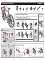
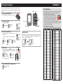
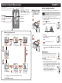
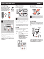
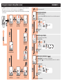
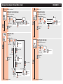
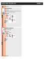
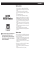
CC-MC200W ENG 1
Warning / Caution
CATEYE
MICRO Wireless
CYCLOCOMPUTER
CC-MC200W
Before using the computer, please thoroughly read
this manual and keep it for future reference.
Please visit our website, where detailed instructions with movies are available and the instruction
manual can be downloaded.
• Do not concentrate on the computer while riding. Ride safely!
• Install the magnet, sensor, and bracket securely. Check these periodically.
• If a child swallows a battery, consult a doctor immediately.
• Do not leave the computer in direct sunlight for a long period of
time.
• Do not disassemble the computer.
• Do not drop the computer to avoid malfunction or damage.
• When using the computer installed on the bracket, change the
MODE by pressing on the four dots below the screen, or by pressing on the SSE simultaneously, to start or stop the timer. Pressing
hard on other areas may result in malfunction or damage to the
computer.
• Be sure to tighten the dial of the FlexTight™ bracket by hand.
Tightening it strongly using a tool, etc. may damage the screw
thread.
• When cleaning the computer, bracket and sensor, do not use thinners, benzene, or alcohol.
• Dispose of used batteries according to local regulations.
• LCD screen may be distorted when viewed through polarized sunglass lenses.
Wireless Sensor
The sensor was designed to receive signals within a maximum range
of 70 cm, to reduce chance of interference. When adjusting the wireless sensor, note the following:
• Signals cannot be received if the distance between the sensor and
the computer is too large. The receiving distance may be shortened due to low temperature and exhausted batteries.
• Signals can be received only when the back of the computer is
facing the sensor.
Interference may occur, resulting in incorrect data, if the computer is:
• Near a TV, PC, radio, motor, or in a car or train.
• Close to a railroad crossing, railway tracks, TV stations and/or radar base.
• Using with other wireless devices in close proximity.
How to install the unit on your bicycle
CC-MC200W ENG 2
1
Bracket
band
Bracket
Dial
Bracket
rubber pad
Sensor
Sensor rubber pad
1Attach the bracket to the stem or handlebar
The FlexTight™ bracket can be attached to either the stem or the handlebar, depending on how the bracket fits into the bracket band.
Caution: Be sure to tighten the dial of the FlexTight™ bracket by hand.
Tightening it strongly using a tool, etc. may damage the screw thread.
When attaching the FlexTight™ bracket to the stem
Bracket band
2
Bracket rubber pad
Nylon ties
(x 2)
Magnet
Remove/Install
the computer
Click
Stem
Dial
Bracket
Install the sensor and magnet
When attaching the FlexTight™ bracket to the handlebar
Bracket band
The distance from the computer to the sensor is within
the transmission data length,
and the back of the computer
faces downward.
The magnet passes through the
sensor zone of the speed sensor.
The clearance between the sensor surface and the magnet is
within 5 mm.
Speed
sensor
SE
Magnet
Speed sensor
OR
While supporting it by hand,
Cut
Handlebar
Bracket
*To mount the bracket to an aero-shaped handlebar or larger stem, use the optional nylon ties
bracket.
Caution:
Round off the cut
edge of the bracket
band to prevent
injury.
Spoke
Speed
sensor
Magnet
SE
OR
Speed sensor
SEN
SOR
NS
ZO
NE
ZO
NE
5 mm
Magnet
*The wheel magnet may be installed
anywhere on the spoke if the installation conditions are satisfied.
Pull
securely
SEN
SO
RZ
ON
E
ZON
E
To the SENSOR ZONE
SENSOR
ZONE
Push it out as if lifting
the front up
2Install the sensor and magnet
NS
SENS
OR ZO
NE
Bracket
rubber pad
Cut
Sensor rubber pad
Magnet
SENSOR
ZONE
Nylon ties
*Install the sensor above the front fork as much as possible.
Preparing the computer
CC-MC200W ENG 3
Perform the clear all data operation as shown below, when you use the
unit for the first time or restore the unit to the condition checked at the
factory.
1Clear all data (initialization)
Tire circumference
Battery case cover
AC
Press the AC button on the back of the computer.
AC
2Select the speed units
Dot section
MENU
Select “km/h” or “mph”.
Register the
setting
km/h ↔ mph
SSE
3Enter the tire circumference
Operation test
Enter the front wheel tire circumference of your
bicycle in mm.
*Use “Tire circumference reference table” as a
guide.
Move digits
Increase Register (Press &
the value
the setting
hold)
MENU
MODE
After installed, check that the computer displays the speed by turning
the front wheel. When it is not displayed, check the installation conditions , and again (page 2).
MODE
4Set the clock
Display format
Pressing and holding the MODE button switches
the display to “Displayed time”, “Hour”, and “Minute” in order.
12h ↔ 24h
Switch the
(AM ↔ PM when
screen or
MODE 12h is selected), or
move digits
MODE
increases the value
Hour
5Press the MENU button to complete setting
Register the setting
(Finish)
MENU
MODE
MENU
MODE
Minute
You can find the tire circumference (L) of your tire size in the chart below, or actually measure the tire circumference (L) of your bicycle.
• How to measure the tire circumference (L)
For the most accurate measurement, do a wheel
roll out. With the tires under proper pressure,
place the valve stem at the bottom. Mark the spot
L mm
on the floor and with the rider’s weight on the
bike, roll exactly one wheel revolution in a straight line (until the
valve comes around again to the bottom). Mark where the valve
stem is and measure the distance.
• Tire circumference reference table
*Generally, the tire size or ETRTO is indicated on the side of the tire.
ETRTO
47-203
54-203
40-254
47-254
40-305
47-305
54-305
28-349
37-349
32-369
40-355
47-355
32-406
35-406
40-406
47-406
50-406
28-451
37-451
37-501
40-501
47-507
50-507
54-507
25-520
28-540
32-540
25-559
32-559
37-559
40-559
47-559
50-559
54-559
Tire size
L (mm)
12x1.75
935
12x1.95
940
14x1.50
1020
14x1.75
1055
16x1.50
1185
16x1.75
1195
16x2.00
1245
16x1-1/8
1290
16x1-3/8
1300
17x1-1/4 (369) 1340
18x1.50
1340
18x1.75
1350
20x1.25
1450
20x1.35
1460
20x1.50
1490
20x1.75
1515
20x1.95
1565
20x1-1/8
1545
20x1-3/8
1615
22x1-3/8
1770
22x1-1/2
1785
24x1.75
1890
24x2.00
1925
24x2.125
1965
24x1(520)
1753
24x3/4 Tubuler 1785
24x1-1/8
1795
24x1-1/4
1905
26x1(559)
1913
26x1.25
1950
26x1.40
2005
26x1.50
2010
26x1.75
2023
26x1.95
2050
26x2.10
2068
ETRTO
57-559
58-559
75-559
28-590
37-590
37-584
20-571
23-571
25-571
40-590
40-584
25-630
28-630
32-630
37-630
18-622
19-622
20-622
23-622
25-622
28-622
30-622
32-622
35-622
38-622
40-622
42-622
44-622
45-622
47-622
54-622
60-622
Tire size
26x2.125
26x2.35
26x3.00
26x1-1/8
26x1-3/8
26x1-1/2
650C Tubuler 26x7/8
650x20C
650x23C
650x25C
26x1(571)
650x38A
650x38B
27x1(630)
27x1-1/8
27x1-1/4
27x1-3/8
700x18C
700x19C
700x20C
700x23C
700x25C
700x28C
700x30C
700x32C
700C Tubuler
700x35C
700x38C
700x40C
700x42C
700x44C
700x45C
700x47C
29x2.1
29x2.3
L (mm)
2070
2083
2170
1970
2068
2100
1920
1938
1944
1952
2125
2105
2145
2155
2161
2169
2070
2080
2086
2096
2105
2136
2146
2155
2130
2168
2180
2200
2224
2235
2242
2268
2288
2326
Operating the computer [Measuring screen]
Sensor signal icon
Flashes in synch with a sensor signal.
CC-MC200W ENG 4
Current speed
0.0 ( :4.0 / :3.0) – 105.9 km/h
[0.0 ( :3.0 / :2.0) – 65.0 mph]
*“Spd” icon is displayed when displaying current speed at the bottom.
Speed unit
Pace arrow
Indicates whether the current speed
is faster ( ) or slower ( ) than the
average speed.
MODE operation when
the computer is mounted on the bracket
Tire size icon
MODE
Auto mode icon
Clock display
Click
Starting / Stopping measurement
There are two measurement methods; manual mode and auto mode.
Setting
method
See “Changing the computer settings: Selecting the auto
mode” (Page 7).
The speed unit (km/h or mph) flashes during measurement.
*The maximum speed and total distance are updated regardless of start/
stop of the measurement.
• Auto mode ( illuminated)
ON
Measurements start automatically when the bicycle is
in motion.
START
Switching computer function
STOP
• Manual mode
Press the SSE button together with the unit to start/
stop the measurement.
Pressing the MODE button switches the measurement data at the bottom in the order shown in the following figure.
OFF
SSE+MODE
Elapsed Time
0:00’00” – 9:59’59”
MODE
Trip Distance
0.00 – 999.99 km [mile] MODE
Click
Trip Distance-2
0.00 – 999.99 km [mile]
SSE
MODE
Starting/Stopping measurement
SSE+MODE
*When the computer is removed from the bracket, press the SSE
button on the front and the MODE button on the back simultaneously.
Resetting data
MODE
Stop watch (*2)
0:00’00 - 9:59’59”
MODE
Total Distance
0 – 99999 km[mile]
MODE
Maximum Speed
0.0 – 105.9 km/h
[0.0 – 65.0 mph]
MODE
*1 When Tm about 10 hours, or Dst exceeds 999.99 km, .E will appear. Reset the data.
*2 It appears only in the auto mode.
Average Speed (*1)
0.0 – 105.9 km/h
[0.0 – 65.0 mph]
Pressing and holding SSE together with the unit on the
measurement screen resets any measurement data, except the total distance (Odo), trip distance-2 (Dst2), and
stopwatch ( ).
SSE+MODE
(Press & hold)
*The total distance (ODO) is not reset.
• Resetting separately the trip distance-2 and stop watch
To reset the currently displayed data, display trip distance 2 (Dst2) or
the stopwatch( ), and hold down the main unit along with the SSE.
*How to reset the trip distance 2 (Dst2) and the
stopwatch displayed in top row of screen
Display the current speed (Spd) in bottom row of
screen and perform the reset operation.
Operating the computer [Various functions]
Backlight (Night mode
)
With the night mode turned on, pressing the MODE
button turns on the backlight (for 5 seconds).
Pressing any button while the backlight is still on
extends the illumination for another 5 seconds.
ON
CC-MC200W ENG 5
Setting the function to display
Upper display selection
Displaying only selected data can be done.
Any data can be selected for the top display, and constantly be displayed.
Tm
MODE
Tm
Dst
Dst2
Av
Odo
Mx
Dst
Av
Mx
MODE
OFF
Setting
method
Setting
method
ON
Pressing and holding the MODE button proceeds to setting
the night mode. Pressing and holding the button again turns
on the night mode, and returns to the measurement screen.
See “Changing the computer settings: Setting the function”
(Page 7).
*The current speed (Spd), and the elapsed time (Tm) cannot be hidden.
*When you hide the function assigned to the top display, the upper display returns to the current speed (Spd).
*The unit keeps recording hidden data on background and each measurement data is updated when displayed (except for the stop watch).
Setting
method
Spd
Tm
Tm
Spd
See “Changing the computer settings: Setting the upper display” (Page 6).
*The stopwatch cannot be set when the auto-mode is off.
Power-saving function
If the computer has not received a signal for 10 minutes, power-saving
screen will activate and only the clock will be displayed. When you press
MODE, or the computer receives a sensor signal, the measuring screen
reappears.
Stop watch
Measuring
screen
MODE
(Press & hold)
Selecting the
night mode
screen
*The night mode is automatically turned off without any signal received
for 10 minutes.
*You can switch ON/OFF also from the menu screen.
See “Changing the computer settings: Setting the night mode” (Page 6).
*When (battery icon) is turned on, the backlight is not turned on even
if the night mode is on.
The time can be measured regardless of start/stop of the measurement.
It can be used when the auto mode is on ( illuminated).
• Start/Stop : Press the SSE button together with the unit.
flashes
during measurement.
• Reset :
Display the stopwatch ( ), and hold down the main
unit along with the SSE button.
*How to reset the trip distance 2 (Dst2) and the stopwatch displayed in top row of screen
Display the current speed (Spd) in bottom row of
screen and perform the reset operation.
ON
Starting/Stopping
measurement
SSE+MODE
=
10 minutes
Power-saving
screen
12 hours
Sleep
MODE
*If another 12 hours of inactivity elapses in the power-saving screen,
only the speed unit is displayed on the screen. With such a screen,
pressing the MODE button returns to the measurement screen.
Changing the computer settings [Menu screen]
CC-MC200W ENG 6
Pressing MENU on the measurement screen changes to the menu screen. Various settings can be changed on the menu screen.
*After changes are made, be sure to register the setting(s) by pressing the MENU button.
*Leaving the menu screen without any operation for 1 minutes returns to the measurement screen, and changes are not saved.
From “Selecting the measurement unit”
Selecting the night mode
Select ON/OFF of the night mode.
*Pressing and holding the MODE button shortcuts to this screen from the measurement
screen.
Changing the settings
MODE
Measuring
screen
MENU
Selecting the
night mode
MODE
Setting the
upper display
Switching the
circumference
MODE
ON ↔ OFF
(Press & hold)
MODE
Register the
setting
MODE
MENU
MODE
Setting the upper display
MODE
Select the function for the upper display.
Changing the settings
MENU
Setting the tire
circumference
Tm
MODE
Dst
Dst2
Av
Odo
Mx
(Press & hold)
MODE
MODE
Selecting the
measurement unit
Spd
Register the
setting
MODE
MENU
Switching the circumference (
Setting the clock
MODE
Changing the settings
MODE
MODE
MODE
Entering the
total distance
Selecting the
auto mode
Register the
setting
Setting the
function
A ↔ B
(Press & hold)
MODE
MODE
)
Switch
and
of the tire circumference currently selected.
*The circumference
is set on a low-speed oriented basis; therefore, it is suitable for
MTB.
MENU
To “Setting the tire circumference”
MODE
Changing the computer settings [Menu screen]
CC-MC200W ENG 7
From “Switching the circumference”
From “Setting the clock”
Setting the tire circumference
Setting the function
Enter the tire circumference.
Select the function to be hidden.
Changing the settings
Changing the settings Dst
MODE
Move digits
(press & hold)
(Press & hold)
0100 – 3999
Register the
setting
MODE
MODE
Increase the value
MODE
Av → Mx → Odo
(Press & hold)
(Press & hold)
MODE
Register the
setting
MODE
MENU
MODE
MENU
Setting the clock
Set the clock.
Changing the settings
Selecting the auto mode
Select ON/OFF of the auto mode.
MODE
12h ↔ 24h
(Press & hold)
24h
12h
Changing the settings
MODE
MODE
(Press & hold)
MODE
(Press & hold)
MODE
MODE
(Press & hold)
Register the
setting
Register the
setting
AM ↔ PM
MENU
MENU
MODE
(Press & hold)
(Press & hold)
MODE
MODE
MODE
Hour
Minute
0 – 23
[1 – 12]
To “Setting the function”
Switch the screen
(press & hold)
Increase the value
00 – 59
MODE
MODE
To “Entering the total distance”
ON ↔ OFF
MODE
ON ↔ OFF
MODE
Changing the computer settings [Menu screen]
From “Selecting the auto mode”
Entering the total distance
Enter the total distance.
*Once you enter any value to the total distance, you can start from the value you entered.
Use this function when you renew and/or reset your unit.
Changing the settings
Increase the value
MODE
MODE
MODE
(Press & hold)
Register the
setting
Move digits
(press & hold)
00000 – 99999
MENU
MODE
Selecting the measurement unit
Select the speed unit (km/h or mph).
Changing the settings
MODE
(Press & hold)
Register the
setting
MENU
MODE
To “Selecting the night mode”
km/h ↔ mph
MODE
CC-MC200W ENG 8
In use
CC-MC200W ENG 9
Maintenance
Troubleshooting
Specification
To clean the computer or accessories, use diluted neutral detergent on a
soft cloth, and wipe it off with a dry cloth.
The sensor signal icon does not flash (the speed is not displayed).
(Move the computer near the sensor, and turn the front wheel. If the sensor
signal icon flashes, this trouble may be a matter of transmission distance
due to battery drain, but not any malfunction.)
Lithium battery (CR2032) x 1 / Approx. 1 years (If the computer
is used for 1 hour/day; the battery life will vary depending on the
conditions of use.)
Lithium battery (CR2032) x 1 / Unit Total Distance reaches about 10000
Sensor :
km (6250 mile)
* It may be shortened significantly when backlight is used frequently.
* This is the average figure of being used under 20 °C temperature and the distance between the computer and the sensor is 65 cm.
* The factory-loaded battery life might be shorter than the above-mentioned specification.
Controller
4 bit, 1-chip microcomputer (Crystal controlled oscillator)
Display
Liquid crystal display
Sensor
No contact magnetic sensor
Transmission
Between 20 and 70 cm
distance
Tire circumference 0100 mm - 3999 mm
range
(Initial value: A = 2096 mm, B = 2050 mm)
0 °F - 104 °F (0 °C - 40 °C) (This product will not display appropriately when
Working exceeding the Working Temperature range. Slow response or black LCD at lower
temperature
or higher temperature may happen respectively.)
Computer :
2-7/64” x 1-27/64” x 11/16” (53.5 x 36 x 17.5 mm) / 0.92 oz (26 g)
Dimensions/weight
Sensor :
1-41/64” x 1-27/64” x 19/32” (41.5 x 36 x 15 mm) / 0.53 oz (15 g)
Replacing the battery
Check that the clearance between the sensor and magnet is not too
large. (Clearance: within 5 mm)
Computer
When (battery icon) is turned on, replace the
CO
battery. Install a new lithium battery(CR2032)
Close IN
with the (+) side facing upward.
*After replacing the computer battery, follow
the procedure described in “Preparing the Open
computer” (Page 3).
Check that the magnet passes through the sensor zone correctly.
Adjust the positions of the magnet and sensor.
Is the computer installed at the correct angle?
CR2032
Back of computer must face toward the sensor.
Check that the distance between the computer and sensor is correct.
(Distance: within 20 to 70 cm)
Install the sensor within the specified range.
Is the computer or sensor battery weak ? In winter, battery performance diminishes.
Sensor
Replace with new batteries according to the procedure specified in the section “Replacing the battery”.
When the speed is not displayed even after adjusting correctly, replace the battery.
CR2032
Replace the computer battery according to the procedure
specified in the section “Replacing the battery”.
Incorrect data appear.
Clear all according to the procedure described in “Preparing
the computer” (Page 3).
IN
Close
CO
Insert new lithium batteries (CR2032) with
the (+) sign upward, and close the battery
cover firmly.
*After replacement, check the positions
of the sensor and magnet.
Nothing is displayed by pressing the button.
Open
Computer :
Battery / Battery life
* The specifications and design are subject to change without notice.
Limited warranty
2-Year Computer/Sensor only
(Accessories and Battery Consumption excluded)
CatEye cycle computers are warranted to be free of defects from materials and workmanship for a period
of two years from original purchase. If the product fails to work due to normal use, CatEye will repair or
replace the defect at no charge. Service must be performed by CatEye or an authorized retailer. To return
the product, pack it carefully and enclose the warranty certificate (proof of purchase) with instruction
for repair. Please write or type your name and address clearly on the warranty certificate. Insurance,
handling and transportation charges to CatEye shall be borne by person desiring service.
For UK and REPUBLIC OF IRELAND consumers, please return to the place of purchase. This does not
affect your statutory rights.
The backlight is not turned on.
Check if (battery icon) is turned on.
Replace the computer battery according to the procedure
specified in the section “Replacing the battery”.
2-8-25, Kuwazu, Higashi Sumiyoshi-ku, Osaka 546-0041 Japan
Attn: CATEYE Customer Service Section
Phone : (06)6719-6863
Fax : (06)6719-6033
E-mail : [email protected]
URL : http://www.cateye.com
[For US Customers]
CATEYE AMERICA, INC.
2825 Wilderness Place Suite 1200, Boulder CO80301-5494 USA
Phone : 303.443.4595
Toll Free : 800.5CATEYE
Fax
: 303.473.0006
E-mail
: [email protected]
Spare accessories
Standard accessories
1602190
1602196
Optional accessories
1600280N
1602193
1699691N
1665150
1602980
CR2032
Parts kit
Speed sensor
Bracket band
Bracket
Wheel magnet
Lithium battery
Nylon tie bracket