1
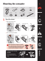
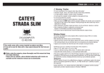
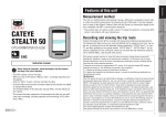
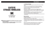
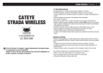
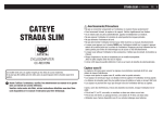
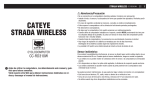
1
C AT E Y E
PADRONE
CYCLOCOMPUTER
CC-PA100W
Mounting the
computer
2
Setting up the
computer
3
Starting
measurement
4
SET
Warning/Caution
Product Warranty, etc.
Appendix
•This instruction manual is subject to change
Changing settings
without notice. See our website for the latest
instruction manual (PDF).
•Please visit our website, where a detailed
Quick Start manual containing videos can be
downloaded.
http://www.cateye.com/en/products/detail/CC-PA100W/manual/
1
1
Mounting the computer
Bracket band
Bracket rubber pad
Bracket
Dial
Speed sensor
Magnet
Sensor rubber pad
Nylon tie
2
(x2)
1 •
Mount the bracket
When mounting on stem
Bracket band
Bracket rubber pad
Stem
3
Bracket
•When mounting on handlebar
Bracket band
Handlebar
Bracket rubber pad
4
Bracket
When mounting the bracket on a handlebar, adjust the angle of the bracket so that
the back of the computer faces the speed
sensor when the computer is attached.
SET
Wrong
Appendix
Cutting band after mounting
Correct
Dial
CAUTION:
Cut the bracket band so
that cut end will not cause
injury.
Cut
2
1
Mounting the computer
2
Mount the speed sensor
Mount the speed sensor in a position where the distance from the
computer to the speed sensor is
within the signal range.
•
Mounting on right front fork
•Mounting on left front fork
2
Max.
70 cm
(27”)
Speed sensor
SEN
SOR
Pull tight
ZON
E
SEN
SO
RZ
ON
E
Cut
Sensor rubber pad
3
3
Nylon tie
4
Mount the magnet
Magnet
Spoke
SET
To sensor zone
Appendix
3
1
Mounting the computer
4
Adjust the speed sensor and the magnet
The magnet passes through
the speed sensor zone.
The clearance between the
speed sensor and the magnet
is within 5 mm (3/16”).
Magnet
Speed sensor
Magnet
Sensor zone
SE
NS
OR
ZO
NE
2
SEN
SOR
ZON
E
5 mm
(3/16”)
Speed sensor
*The magnet may be mounted at any position on spoke as long as attachment
conditions are satisfied.
5
Attach/detach computer
Hold computer.
Click
Push out so that front lifts up.
6
3
4
SET
Test operation
After attaching the computer, rotate the front wheel gently to check that current
speed is displayed on the computer.
If the speed is not displayed, refer to the attachment conditions in steps 1, 2, and 4
Appendix
again.
4
1
Setting up the computer
Battery case
cover
When using the
computer for the
first time, configure
the initial settings.
MODE
MENU
AC
Long press (2 sec.)
MODE
Dot section
1
Short press
MODE
2
Clear all data.
AC
Press the AC button on the back of the computer.
*All data is deleted and the computer is reset
to its factory default settings.
2
Select the measurement unit.
km/h ↔ mph
Select “km/h” or “mph”.
MODE
MENU Confirm
3
Set tire circumference.
Increase
numbers
MODE
Enter the tire circumference of the front wheel
in mm.
Move to
next digit
(Press and
MODE hold)
*Refer to “Tire circumference”.
MENU Confirm
4
Set the clock.
4
Time display mode
Each time MODE is pressed and held, settings
switch from time display mode, to hours, to
minutes.
Hours
MODE
Minutes
Switch item
or increase
numbers
Switch screen
or move to
next digit
MODE (Press and
hold)
Press MENU to complete setup.
Setup is completed and the computer switches to the measurement screen. For instructions on how to start measurement, refer to “Starting measurement”.
5
SET
MENU
Setup complete
Appendix
5
3
1
Setting up the computer
Tire circumference
Tire circumference can be determined by either of the following two methods:
•Measure the actual tire circumference (L)
After ensuring that the tire pressure is appropriate, sit on your
bike, roll it forward so that the tire makes one full revolution (use
the valve or other marking as a reference), and measure the distance traveled on the road.
•Tire size chart
L mm
2
*The tire size or ETRTO code is indicated on the side of the tire.
ETRTO
47-203
54-203
40-254
47-254
40-305
47-305
54-305
28-349
37-349
32-369
40-355
47-355
32-406
35-406
40-406
47-406
50-406
28-451
37-451
37-501
40-501
47-507
50-507
54-507
25-520
L (mm)
ETRTO
935
940
1020
1055
1185
1195
1245
1290
1300
1340
1340
1350
1450
1460
1490
1515
1565
1545
1615
1770
1785
1890
1925
1965
1753
1785
1795
1905
1913
1950
2005
2010
2023
2050
2068
2070
2083
75-559
28-590
37-590
37-584
20-571
23-571
25-571
40-590
40-584
25-630
28-630
32-630
37-630
40-584
54-584
57-584
18-622
19-622
20-622
23-622
25-622
28-622
30-622
32-622
35-622
38-622
40-622
42-622
44-622
45-622
47-622
54-622
56-622
60-622
6
Tire size
26x3.00
26x1-1/8
26x1-3/8
26x1-1/2
650C Tubular 26x7/8
650x20C
650x23C
650x25C 26x1(571)
650x38A
650x38B
27x1(630)
27x1-1/8
27x1-1/4
27x1-3/8
27.5x1.50
27.5x2.1
27.5x2.25
700x18C
700x19C
700x20C
700x23C
700x25C
700x28C
700x30C
700x32C
700C Tubular
700x35C
700x38C
700x40C
700x42C
700x44C
700x45C
700x47C
29x2.1
29x2.2
29x2.3
L (mm)
2170
1970
2068
2100
1920
1938
1944
1952
2125
2105
2145
2155
2161
2169
2079
2148
2182
2070
2080
2086
2096
2105
2136
2146
2155
2130
2168
2180
2200
2224
2235
2242
2268
2288
2298
2326
3
4
SET
Appendix
28-540
32-540
25-559
32-559
37-559
40-559
47-559
50-559
54-559
57-559
58-559
Tire size
12x1.75
12x1.95
14x1.50
14x1.75
16x1.50
16x1.75
16x2.00
16x1-1/8
16x1-3/8
17x1-1/4 (369)
18x1.50
18x1.75
20x1.25
20x1.35
20x1.50
20x1.75
20x1.95
20x1-1/8
20x1-3/8
22x1-3/8
22x1-1/2
24x1.75
24x2.00
24x2.125
24x1(520)
24x3/4 Tubular
24x1-1/8
24x1-1/4
26x1(559)
26x1.25
26x1.40
26x1.50
26x1.75
26x1.95
26x2.10
26x2.125
26x2.35
Starting measurement [Measurement screen]
1
MODE operation when mounted on bracket
Current speed
0.0 (4.0) – 99.9 km/h
[0.0 (3.0) – 65.9 mph]
MODE
Measurement unit
Current function
When the computer is mounted on the bracket,
pressing the dot section on the computer
depresses the MODE button.
2
Switching current function
Pressing MODE switches the current function displayed at the bottom of the screen.
MODE
Elapsed Time
0:00’00” – 99:59’59”
3
MODE
Trip Distance
0.00 – 9999.99 km [miles]
Average Speed
0.0 – 99.9 km/h [0.0 – 65.9 mph]
MODE
MODE
4
MODE
MODE
SET
Clock
0:00 – 23:59 or 1:00 – 12:59
Total distance
0.0 – 99999.9 km [miles]
Maximum Speed
0.0 (4.0) – 99.9 km/h [0.0 (3.0) – 65.9 mph]
MENU
On the measurement screen, press MENU to go to the menu
screen. Various settings can be changed on the menu screen.
7
Appendix
*Av displays .E instead of the measurement value when Tm exceeds approximately
100 hours or Dst exceeds 9999.99 km. Reset the computer.
Starting measurement [Measurement screen]
1
Starting/stopping measurement
Measurement starts automatically when the bicycle
moves. During measurement the measurement unit (km/h or
mph) flashes.
Measurement
starts
Measurement
stops
2
Resetting data
Pressing and holding MODE when on the measurement screen resets
all measurement data to 0 (excluding Odo).
MODE
(Press and hold)
Power-saving function
If the computer does not receive
any signal for 10 minutes, the power-saving screen is activated and
only the clock is displayed. If MODE is pressed or a sensor
signal is received while the powersaving screen is activated, the computer returns to the measurement
screen.
Power-saving
screen
3
10 minutes
1 hour
Sleep
*When the computer is left on
the power-saving screen for 1
hour, the display only shows the
measurement unit. When the
computer is in this state, you can
return to the measurement screen
by pressing MODE.
MODE
4
SET
Appendix
8
1
Changing settings [Menu screen]
On the measurement screen, press MENU to go to the menu screen. Various settings can be changed on the menu screen.
*After changing settings, always press MENU to confirm changes.
*When the menu screen is left on for 1 minute, the computer returns to the measurement screen.
Measurement
screen
Menu screen
Description
Tire circumference
2
Lets you set the tire circumference.
MENU
Change setting
Increase
numbers
MODE
MODE
(Press and hold)
Move to
next digit
MODE
(Press and hold)
MENU
MODE
Confirm
Increase
numbers
MENU
MODE
3
Clock
Lets you set the clock.
Change setting
Select display
12h ↔ 24h
MODE
4
MODE
(Press and hold)
Confirm
MODE
MENU
MODE
(Press and hold)
Manual
distance
input
Set “hours”
Increase
numbers
MODE
MODE
(Press
and hold)
MODE
MODE
(Press and hold)
Select
measurement unit
Set “minutes”
Increase
numbers
MODE
9
Appendix
MODE
SET
1
Changing settings [Menu screen]
Measurement
screen
Menu screen
Description
Tire circumference
MENU
2
MODE
Clock
MODE
Manual distance input
Lets you set total distance traveled manually. (Fractions cannot be entered.)
*Setting an arbitrary value for total distance allows
you to start from the value you entered. This is useful when you have just purchased a new
bicycle or when replacing the computer battery.
Change setting
3
Increase
numbers
MENU
MODE
MODE
(Press and hold)
Move to
next digit
MODE
MODE
(Press and hold)
Confirm
4
Increase
numbers
MENU
MODE
SET
MODE
Select measurement unit
Lets you select the measurement unit (km/h or mph).
(Press
km/h ↔ mph
MODE and hold)
MODE
Confirm
MENU
10
Appendix
Change setting
1
Appendix
Warning / Caution
•Do not concentrate on the computer while riding. Always ride safely.
•Mount the magnet, sensor, and bracket securely, and check them periodically to ensure that they are not loose.
•If a battery is swallowed accidentally, consult a doctor immediately.
•Do not leave the computer in direct sunlight for a long period of time.
•Do not disassemble the computer.
•Do not drop the computer. Doing so may result in malfunction or damage.
•When pressing the MODE button with the computer installed on the bracket, press the
2
area around the dot section on the front of the computer. Pressing other areas strongly
may result in malfunction or damage.
•Always tighten the bracket band dial by hand. Using a tool or other object to tighten the
dial may crush the screw thread.
•When cleaning the computer and accessories, do not use thinners, benzine, or alcohol.
•Risk of explosion if battery is replaced by an incorrect type.
Dispose of used batteries according to local regulations.
•The LCD screen may be distorted when viewed through polarized sunglass lenses.
3
Wireless Sensor
The speed sensor is designed with a maximum signal range of 70 cm (27”), to reduce
the chance of interference. (The signal range is intended to serve as a rough guide only.)
When handling the wireless sensor, note the following:
•Signals cannot be received if the distance between the speed sensor and the computer
is too large.
•Signal range may be shortened due to low temperature and flat batteries.
•Signals can be received only when the back of the computer is facing the speed sensor.
4
Interference may occur, resulting in malfunction, if the computer is:
•Near a TV, PC, radio, or motor, or in a car or train.
•Close to a railroad crossing, railway tracks, TV transmitter station, or radar station.
•Used with other wireless devices or certain battery-powered lights.
Hereby, CATEYE Co., Ltd., declares that this CC-PA100W is in compliance with the essential requirements
and other relevant provisions of Directive 1999/5/EC.
11
Appendix
This device complies with Part 15 of the FCC Rules. Operation is subject to the following two conditions:(1)This device may not cause harmful interference, and (2) this device must accept any interference received, including interference that may cause undesired operation.
Modifications
The FCC requires the user to be notified that any changes or modifications made to this device that are
not expressly approved by CatEye Co., Ltd. May void the user ’s authority to operate the equipment.
SET
1
Appendix
Maintenance
If the computer or accessories become dirty, clean with a soft cloth which is moistened
with mild soap.
Replacing the battery
• Computer
When the display becomes dim, replace the battery. Insert a new lithium battery (CR2032) with the (+) side up.
*After replacing the battery, always follow the procedure described in “Setting up the computer”.
Close
CO
IN
Open
CR2032
2
*If you make a note of the total distance value before replacing the battery, you will be able to continue from the same
total distance by entering it after replacing the battery.
• Speed sensor
When the speed is not displayed even after adjusting correctly, it is time to replace the battery.
Insert a new lithium battery (CR2032) with the (+) side up
and close the battery cover firmly.
IN
Close
3
CO
*After replacing the battery, adjust the position of the
magnet relative to the speed sensor as described in
“Mounting the computer” step 4.
CR2032
Open
Troubleshooting
The sensor signal reception icon does not flash. (Speed is not displayed.)
Is there too much clearance between the speed sensor and the magnet? (Clearance should be within 5 mm (3/16”).)
Does the magnet pass through the sensor zone correctly?
Adjust the position of the magnet and/or the speed sensor.
Is the computer mounted at the correct angle?
Ensure that the back of the computer faces the speed sensor.
Are the computer and the speed sensor mounted at the correct distance apart? (Clearance should be from 20 to 70 cm (8” to 27”).)
Ensure that the speed sensor is within range.
Is the computer or speed sensor battery flat?
*Battery performance diminishes in winter.
If the computer reacts only when it is close to the speed sensor, the problem may
be due to weak batteries.
Replace the batteries with new ones as described in “Replacing the battery”.
The display remains blank when the button is pressed.
Replace the computer battery as described in “Replacing the battery”.
Incorrect data appear.
Clear all according to the procedure described in “Setting up the computer”.
•
•
•
•
4
SET
•
Appendix
12
1
Appendix
Main specifications
Batteries used
Battery life
Computer
Lithium battery (CR2032) x1 / Approx. 1 year
(If used for 1 hour a day; actual battery life will vary depending on
usage conditions.)
Speed sensor
Lithium battery (CR2032) x1 /
Total distance approx. 10000 km [6,250 miles]
* Average value when used at temperature of 20 °C with computer and sensor mounted 65 cm apart.
* Life of pre-installed battery may be shorter than indicated above.
Controller
4 bit, 1-chip microcomputer
(Crystal controlled oscillator)
Display
Liquid crystal
Sensor
Non-contact magnetic sensor
Signal range
20 to 70 cm (8” to 27”)
Tire circumference range
0100 mm – 3999 mm
(Initial value: 2096 mm)
Operating temperature range
32°F – 104°F (0°C – 40°C)
(Guaranteed operating temperature range: Display visibility may deteriorate outside
this range.)
Dimensions/
weight
Computer
2-21/32” x 1-11/16” x 9/16” (67.5 x 43 x 14.5 mm) / 1.1 oz (31.5 g)
Speed sensor
1-5/8” x 1-13/32” x 19/32” (41.5 x 36 x 15 mm) / 0.5 oz (15 g)
2
3
* Specifications and design are subject to change without notice.
LIMITED WARRANTY
2-Years Computer/Speed Sensor Only
(Accessories and Battery Consumption Excluded)
CatEye cycle computers are warranted to be free of defects from materials and workmanship for a period of two
years from original purchase. If the product fails to work
due to normal use, CatEye will repair or replace the defect
at no charge. Service must be performed by CatEye or an
authorized retailer. To return the product, pack it carefully
and enclose the warranty certificate (proof of purchase)
with instruction for repair. Please write or type your name
and address clearly on the warranty certificate. Insurance,
handling and transportation charges to CatEye shall be
borne by person desiring service.
For UK and REPUBLIC OF IRELAND consumers, please
return to the place of purchase. This does not affect your
statutory rights.
[For US Customers]
CATEYE AMERICA, INC.
2825 Wilderness Place Suite 1200, Boulder CO 80301-5494
USA
Phone: 303.443.4595
Toll Free: 800.5.CATEYE
Fax : 303.473.0006
E-mail : [email protected]
13
1602190N
Parts kit
1600280N
Bracket band
1602193
Bracket
1665150
Lithium battery
1602196
Speed sensor
(SPD-01)
1699691N
Wheel magnet
Optional accessories
1602980
Nylon tie bracket
4
SET
Appendix
2-8-25, Kuwazu, Higashi Sumiyoshi-ku, Osaka 546-0041 Japan
Attn: CATEYE Customer Service
Phone: (06)6719-6863
Fax : (06)6719-6033
E-mail: [email protected] URL : http://www.cateye.com
Standard accessories