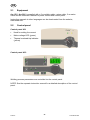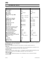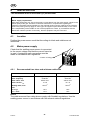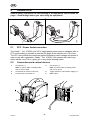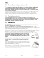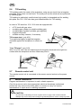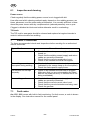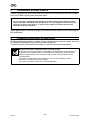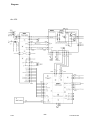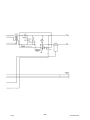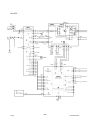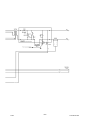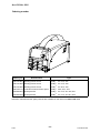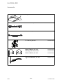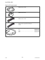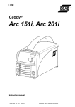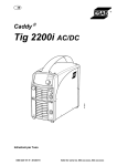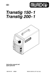
1
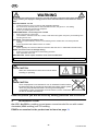
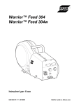
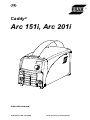
GB Caddy ® Arc 151i, Arc 201i Instruction manual 0460 446 101 GB 20110628 Valid for serial no. 927-xxx-xxxx -2- 1 SAFETY . . . . . . . . . . . . . . . . . . . . . . . . . . . . . . . . . . . . . . . . . . . . . . . . . . . . . . . . . . . 2 INTRODUCTION . . . . . . . . . . . . . . . . . . . . . . . . . . . . . . . . . . . . . . . . . . . . . . . . . . . 2.1 2.2 4 5 Equipment . . . . . . . . . . . . . . . . . . . . . . . . . . . . . . . . . . . . . . . . . . . . . . . . . . . . . . . . . . . . . . . . Control panel . . . . . . . . . . . . . . . . . . . . . . . . . . . . . . . . . . . . . . . . . . . . . . . . . . . . . . . . . . . . . 6 6 3 TECHNICAL DATA . . . . . . . . . . . . . . . . . . . . . . . . . . . . . . . . . . . . . . . . . . . . . . . . . 4 INSTALLATION . . . . . . . . . . . . . . . . . . . . . . . . . . . . . . . . . . . . . . . . . . . . . . . . . . . . 7 8 4.1 Location . . . . . . . . . . . . . . . . . . . . . . . . . . . . . . . . . . . . . . . . . . . . . . . . . . . . . . . . . . . . . . . . . . 4.2 Mains power supply . . . . . . . . . . . . . . . . . . . . . . . . . . . . . . . . . . . . . . . . . . . . . . . . . . . . . . . . 4.2.1 Recommended fuse sizes and minimum cable area . . . . . . . . . . . . . . . . . . . . . . . 8 8 8 5 OPERATION . . . . . . . . . . . . . . . . . . . . . . . . . . . . . . . . . . . . . . . . . . . . . . . . . . . . . . . 9 5.1 5.2 5.3 5.4 5.5 5.6 5.7 PFC - Power factor correction . . . . . . . . . . . . . . . . . . . . . . . . . . . . . . . . . . . . . . . . . . . . . . . Connections and control devices . . . . . . . . . . . . . . . . . . . . . . . . . . . . . . . . . . . . . . . . . . . . Connection of welding and return cable . . . . . . . . . . . . . . . . . . . . . . . . . . . . . . . . . . . . . . . Overheating protection . . . . . . . . . . . . . . . . . . . . . . . . . . . . . . . . . . . . . . . . . . . . . . . . . . . . . MMA welding . . . . . . . . . . . . . . . . . . . . . . . . . . . . . . . . . . . . . . . . . . . . . . . . . . . . . . . . . . . . . TIG welding . . . . . . . . . . . . . . . . . . . . . . . . . . . . . . . . . . . . . . . . . . . . . . . . . . . . . . . . . . . . . . . Remote control unit . . . . . . . . . . . . . . . . . . . . . . . . . . . . . . . . . . . . . . . . . . . . . . . . . . . . . . . . 9 9 10 10 10 11 11 6 MAINTENANCE . . . . . . . . . . . . . . . . . . . . . . . . . . . . . . . . . . . . . . . . . . . . . . . . . . . . 11 6.1 Inspection and cleaning . . . . . . . . . . . . . . . . . . . . . . . . . . . . . . . . . . . . . . . . . . . . . . . . . . . . 12 7 FAULT-TRACING . . . . . . . . . . . . . . . . . . . . . . . . . . . . . . . . . . . . . . . . . . . . . . . . . . 12 7.1 Fault codes . . . . . . . . . . . . . . . . . . . . . . . . . . . . . . . . . . . . . . . . . . . . . . . . . . . . . . . . . . . . . . . 12 8 ORDERING SPARE PARTS . . . . . . . . . . . . . . . . . . . . . . . . . . . . . . . . . . . . . . . . . 9 DISMANTLING AND SCRAPPING . . . . . . . . . . . . . . . . . . . . . . . . . . . . . . . . . . . DIAGRAM . . . . . . . . . . . . . . . . . . . . . . . . . . . . . . . . . . . . . . . . . . . . . . . . . . . . . . . . . . . . ORDERING NUMBER . . . . . . . . . . . . . . . . . . . . . . . . . . . . . . . . . . . . . . . . . . . . . . . . . ACCESSORIES . . . . . . . . . . . . . . . . . . . . . . . . . . . . . . . . . . . . . . . . . . . . . . . . . . . . . . . 13 13 14 18 19 Rights reserved to alter specifications without notice. TOCe -3- GB 1 SAFETY Users of ESAB welding equipment have the ultimate responsibility for ensuring that anyone who works on or near the equipment observes all the relevant safety precautions. Safety precautions must meet the requirements that apply to this type of welding equipment. The following recommendations should be observed in addition to the standard regulations that apply to the work place. All work must be carried out by trained personnel well-acquainted with the operation of the welding equipment. Incorrect oper ation of the equipment may lead to hazardous situations which can result in injury to the operator and damage to the equipment. 1. Anyone who uses the welding equipment must be familiar with: its operation location of emergency stops its function relevant safety precautions welding 2. The operator must ensure that: no unauthorized person is stationed within the working area of the equipment when it is started up. no-one is unprotected when the arc is struck 3. The workplace must: be suitable for the purpose be free from drafts 4. Personal safety equipment Always wear recommended personal safety equipment, such as safety glasses, flame-proof clothing, safety gloves. Do not wear loose-fitting items, such as scarves, bracelets, rings, etc., which could become trapped or cause burns. 5. General precautions Make sure the return cable is connected securely. Work on high voltage equipment may only be carried out by a qualified electrician. Appropriate fire extinquishing equipment must be clearly marked and close at hand. CAUTION This product is solely intended for arc welding. WARNING Do not use the power source for thawing frozen pipes. -4bh32d1e © ESAB AB 2008 GB WARNING Arc welding and cutting can be injurious to yourself and others. Take precausions when welding and cutting. Ask for your employer's safety practices which should be based on manufacturers' hazard data. ELECTRIC SHOCK - Can kill Install and earth the unit in accordance with applicable standards. Do not touch live electrical parts or electrodes with bare skin, wet gloves or wet clothing. Insulate yourself from earth and the workpiece. Ensure your working stance is safe. FUMES AND GASES - Can be dangerous to health Keep your head out of the fumes. Use ventilation, extraction at the arc, or both, to take fumes and gases away from your breathing zone and the general area. ARC RAYS - Can injure eyes and burn skin. Protect your eyes and body. Use the correct welding screen and filter lens and wear protective clothing. Protect bystanders with suitable screens or curtains. FIRE HAZARD Sparks (spatter) can cause fire. Make sure therefore that there are no inflammable materials nearby. NOISE - Excessive noise can damage hearing Protect your ears. Use earmuffs or other hearing protection. Warn bystanders of the risk. MALFUNCTION - Call for expert assistance in the event of malfunction. Read and understand the instruction manual before installing or operating. PROTECT YOURSELF AND OTHERS! CAUTION Read and understand the instruction manual before installing or operating. CAUTION Class A equipment is not intended for use in residential locations where the electrical power is provided by the public low-voltage supply system. There may be potential difficulties in ensuring electromagnetic compatibility of class A equipment in those locations, due to conducted as well as radiated disturbances. ESAB can provide you with all necessary welding protection and accessories. 2 INTRODUCTION Arc 151i, Arc 201iis a welding current power source intended for use with coated electrodes (MMA welding) and TIG welding. ESAB's accessories for the product can be found on page 19. -5bh32d1e © ESAB AB 2008 GB 2.1 Equipment Arc 151i, Arc 201i is supplied with a 3 m welding cable, return cable, 3 m mains cable and an instruction manual for power source and control panel. Instruction manuals in other languages can be downloaded from the website, www.esab.com. 2.2 Control panel Control panel A31 Knob for setting the current Mains voltage LED (green) Thermal overload trip indicator (yellow) Control panel A33 Welding process parameters are controlled via the control panel. NOTE! See the separate instruction manual for a detailed description of the control panel. -6bh32d1e © ESAB AB 2008 GB 3 TECHNICAL DATA Mains voltage Primary current Imax TIG Imax MMA Mains supply No-load power Voltage/current range, MMA A31 A33 Voltage/current range TIG Permissible load at MMA 25% duty cycle 60% duty cycle 100% duty cycle Permissible load at TIG 20% duty cycle 25% duty cycle 60% duty cycle 100% duty cycle Power factor at maximum current Efficiency at maximum current Open-circuit voltage A31 without VRD function 1) A33 VRD function deactivated 2) VRD function activated 2) Operating temperature Transportation temperature Constant A-weighted sound pressure Dimensions, l x b x h Weight with A31 with A33 Enclosure class Application class Arc 151i 230 V, 1 50/60 Hz Arc 201i 230 V, 1 50/60 Hz 13.8 A 21.3 A Zmax 0.35 ohm 30 W 24.1 A 24.9 A Zmax 0.30 ohm 30 W 8 A /20 V - 150 A /26 V 4 A /20 V - 150 A /26 V 3 - 150 A 4 A /20 V - 170 A /26.8 V 3 - 220 A 150 A / 26.0 V 100 A / 24.0 V 90 A / 23.6 V 170 A / 26.8 V 130 A / 25.2 V 110 A / 24.4 V 150 A / 16.0 V 120 A / 14.8 V 110 A / 14.4 V 0.99 80% 220 A / 18.8 V 150 A / 16.0 V 140 A / 15.6 V 0.99 81% 58 - 72 V 55 - 60 V < 35 V -10° C - +40° C -20° C - +55° C < 70 dB 418 x 188 x 208 mm 55 - 60 V < 35 V -10° C - +40° C -20° C - +55° C < 70 dB 418 x 188 x 208 mm 7.9 kg 8.1 kg IP 23 8.3 kg IP 23 1) Valid for power sources without VRD specification on the rating plate. 2) Valid for power sources with VRD specification on the rating plate. The VRD function is explained in the instruction manual for the control panel. Mains supply, Zmax Maximum permissible line impedance of the network in accordance with IEC 61000-3-11. Duty cycle The duty cycle refers to the time as a percentage of a ten-minute period that you can weld or cut at a certain load without overloading. The duty cycle is valid for 40° C. Enclosure class The IP code indicates the enclosure class, i. e. the degree of protection against penetration by solid objects or water. Equipment marked IP23 is designed for indoor and outdoor use. Application class The symbol indicates that the power source is designed for use in areas with increased electrical hazard. -7bh32d1e © ESAB AB 2008 GB 4 INSTALLATION The installation must be executed by a professional. Note Mains supply requirements High power equipment may, due to the primary current drawn from the mains supply, influence the power quality of the grid. Therefore connection restrictions or requirements regarding the maximum permissible mains impedance or the required minimum supply capacity at the interface point to the public grid may apply for some types of equipment (see technical data). In this case it is the responsibility of the installer or user of the equipment to ensure, by consultation with the distrubution network operator if necessary, that the equipment may be connected. 4.1 Location Position the power source such that its cooling air inlets and outlets are not obstructed. 4.2 Mains power supply Check that the welding power source is connected to the correct voltage and that the correct fuse size is used. A protective earth connection must be made in accordance with regulations Location of rating plate 4.2.1 Recommended fuse sizes and minimum cable area Mains voltage Mains frequency Mains cable, area Phase current I1eff Welding cable, area Fuse anti-surge type C MCB Arc 151i Arc 201i 230 V 10 %, 1-phase 230 V 10 %, 1-phase 50-60 Hz 50-60 Hz 3G2.5 mm2 3G2.5 mm2 11.5 A 13.4 A 16 mm2 16 mm2 16 A 13 A 16 A 16 A NOTE! The cable area and fuse rating above comply with Swedish regulations. Use the welding power source in accordance with the relevant national regulations. -8bh32d1e © ESAB AB 2008 GB 5 OPERATION General safety regulations for the handling of the equipment can be found on page 4. Read through before you start using the equipment! 5.1 PFC - Power factor correction The Caddy Arc 151i/201i are 230 V single-phase power sources equipped with a PFC circuit making it possible to use the full range of the machine on a 16 A fuse. The PFC also protects the machines against fluctuating mains voltage and makes it safer to use with a generator. Caddy Arc 151i/201i can operate with extra long mains cables, over 100 m, giving you a very larger working radius. 5.2 Connections and control devices 1 Connection (+) MMA: for return cable or welding cable TIG: for return cable 4 Connection (+) MMA: for return cable or welding cable TIG: for Tig torch l 2 Connection for remote control unit 5 Toggle switch for mains power supply 0 / 1 3 Control panel, see under 2.2 6 Mains cable -9bh32d1e © ESAB AB 2008 GB 5.3 Connection of welding and return cable The power source has two outputs, a positive terminal (+) and a negative terminal (-), for connecting welding and return cables. The output to which the welding cable is connected depends on the type of electrode used. The connecting polarity is stated on the electrode packaging. Connect the welding cable to the terminal stated on the electrode packaging. Connect the return cable to the other output on the power source. Secure the return cable's contact clamp to the work piece and ensure that there is good contact between the work piece and the output for the return cable on the power source. 5.4 Overheating protection The welding power source has a thermal overload trip which operates if the temperature becomes too high, interrupting the welding current and lighting a yellow indicating lamp on the front of the power source. The thermal overload trip resets automatically when the temperature has fallen. 5.5 MMA welding Arc 151i / 201i gives direct current, and you can weld most metals to alloy and nonalloy steel, stainless steel and cast iron. Arc 151i / 201i allows you to weld most coated electrodes from Ø 1.6 to Ø 3.25. MMA welding may also be referred to as welding with coated electrodes. Striking the arc melts the electrode, and its coating forms protective slag. If, when striking the arc, the tip of the electrode is pressed against the metal, it immedi ately melts and sticks to the metal, rendering continued welding impossible. Therefore, the arc has to be struck in the same way that you would light a match. Quickly strike the electrode against the metal, then raise it so as to give an appropriate arc length (approx. 2 mm). If the arc is too long, it will crackle and spit before finally going out com pletely. If you are working on a welding bench, check before attempting to strike the arc that residual waste metal, pieces of electrode or other objects on the bench do not insulate the part to be welded. cmha2p11 Once the arc has been struck, move the electrode from left to right. The electrode must be at an angle of 60° to the metal in relation to the direction of welding. When you want to weld wide beads, or when you want the weld to be so thick that you have to weld in a number of layers, how ever, you have to use lateral movements. cmha2p10 - 10 bh32d1e © ESAB AB 2008 GB 5.6 TIG welding TIG welding melts the metal of the workpiece, using an arc struck from a tungsten electrode, which does not itself melt. The weld pool and the electrode are protected by shielding gas. TIG welding is particularly useful where high quality is demanded and for welding thin plate. Arc 151i / 201i also has good characteristics for TIG welding. In order to TIG weld Arc 151i / 201i must be equipped with: a TIG torch with gas valve a welding gas cylinder (a suitable welding gas) a welding gas regulator (suitable gas regulator) tungsten electrode suitable auxiliary material, if necessary. TIG scrape start (only A31) To scrape start lightly scrape the tungsten electrode against the workpiece to create an arc. ”Live TIG-start” (only A33) With “Live TIG start” the arc strikes when the tungsten electrode is brought into contact with the workpiece and then lifted away from it. 5.7 Remote control unit The remote control unit is connected to the remote control socket on the power source. 6 MAINTENANCE Regular maintenance is important for safe, reliable operation. Only those persons who have appropriate electrical knowledge (authorized personnel) may remove the safety plates to connect or carry out service, maintenance or repair work on welding equipment. CAUTION All guarantee undertakings from the supplier cease to apply if the customer himself attempts any work in the product during the guarantee period in order to rectify any faults. - 11 bh32d1e © ESAB AB 2008 GB 6.1 Inspection and cleaning Power source Check regularly that the welding power source is not clogged with dirt. How often and which cleaning methods apply depend on: the welding process, arc times, placement, and the surrounding environment. It is normally sufficient to blow down the power source with dry compressed air (reduced pressure) once a year. Clogged or blocked air inlets and outlets otherwise result in overheating. TIG torch The TIG torch's wear parts should be cleaned and replaced at regular intervals in order to achieve trouble-free welding. 7 FAULT-TRACING Try these recommended checks and inspections before sending for an authorized service technician. Corrective action Type of fault No arc. Check that the mains power supply switch is turned on. Check that the welding current supply and return cables are correctly connected. Check that the correct current value is set. Check to see whether the MCB has tripped. The welding current is interrupted during welding. The thermal cut-out trips frequently. Check to see whether the dust filter is clogged. Make sure that you are not exceeding the rated data for the power source (i.e. that the unit is not being overloaded). Poor welding performance. Check that the welding current supply and return cables are correctly connected. Check that the correct current value is set. Check that the correct electrodes are being used. Check the gas flow. 7.1 Check whether the thermal cut-outs have tripped (indicated by the orange lamp on the front panel). Check the mains power supply fuses. Fault codes Arc 151i, 201i comes with built-in fault monitoring. If a fault occurs, a code is shown in the display. See instruction manual for the control panel. - 12 bh32d1e © ESAB AB 2008 GB 8 ORDERING SPARE PARTS Repair and electrical work should be performed by an authorized ESAB serviceman. Use only ESAB original spare and wear parts. Arc 151i, Arc 201i is designed and tested in accordance with the international and Eu ropean standards EN 60974-1 and IEC 60974-10 . It is the obligation of the service unit which has carried out the service or repair work to make sure that the product still conforms to the said standard. Spare parts may be ordered through your nearest ESAB dealer, see the last page of this publication. 9 DISMANTLING AND SCRAPPING Welding equipment primarily consists of steel, plastic and non-ferrous metals, and must be handled according to local environmental regulations. Coolant must also be handled according to local environmental regulations. Dispose of electronic equipment at the recycling facility! In observance of European Directive 2002/96/EC on Waste Electrical and Electronic Equipment and its implementation in accordance with national law, electrical and/or electronic equipment that has reached the end of its life must be disposed of at a recycling facility. As the person responsible for the equipment, it is your responsibility to obtain information on approved collection stations. For further information contact the nearest ESAB dealer. - 13 bh32d1e © ESAB AB 2008 Diagram Arc 151i - 14 bh32e © ESAB AB 2008 - 15 bh32e © ESAB AB 2008 Arc 201i - 16 bh32e © ESAB AB 2008 - 17 bh32e © ESAB AB 2008 Arc 151i/Arc 201i Ordering number Ordering no. Denomination Type 0460 445 881 Welding Power source Caddyâ Arc 151i, A31 0460 445 883 Welding Power source Caddyâ Arc 151i, A33 0460 445 884 Welding Power source Caddyâ Arc 201i, A33 0460 449 174 Instruction manual Control panel Caddyâ A32, A33, A34 0459 839 027 Spare parts list Caddyâ Arc 151i, Arc 152i, A31 0459 839 028 Spare parts list Caddyâ Arc 151i, Arc 201i, A33 Instruction manuals and the spare parts list are available on the Internet at www.esab.com - 18 bh32o © ESAB AB 2008 Arc 151i/Arc 201i Accessories Strap . . . . . . . . . . . . . . . . . . . . . . . . . . . . . . . . . . . 0460 265 001 Cable holder 2 pcs . . . . . . . . . . . . . . . . . . . . . . 0460 265 002 Shoulder strap . . . . . . . . . . . . . . . . . . . . . . . . . . 0460 265 003 Trolley . . . . . . for 5-10 litre gasbottle . . . . . . . . . . . . . . . . . . . . . 0459 366 885 Welding cable kit, Arc 151i . . . . . . . . . . . . . . Return cable kit, Arc 151i . . . . . . . . . . . . . . . . Welding cable kit, Arc 201i . . . . . . . . . . . . . . . Return cable kit, Arc 201i . . . . . . . . . . . . . . . . 0700 006 898 0700 006 899 0700 006 900 0700 006 901 Tig torch TXH 150V, Arc 151i . . . . . . . . . . . . 0460 011 843 Tig torch TXH 200V, Arc 201i . . . . . . . . . . . . . 0460 012 841 - 19 bh32a © ESAB AB 2008 Arc 151i/Arc 201i Only for A33 control panel Remote control MMA 1 (10 m cable) . . . . . . . 0349 501 024 MMA and TIG: current Foot control FS002 . . . . . . . . . . . . . . . . . . . . . . 0349 090 886 MMA and TIG current Remote control unit AT1 . . . . . . . . . . . . . . . . . 0459 491 896 MMA and TIG: current Remote control unit AT1 CF . . . . . . . . . . . . . 0459 491 897 MMA and TIG: rough and fine setting of current. Remote cable 12 pole - 8 pole 5m ..................................... 10 m . . . . . . . . . . . . . . . . . . . . . . . . . . . . . . . . . . . . 15 m . . . . . . . . . . . . . . . . . . . . . . . . . . . . . . . . . . . . 25 m . . . . . . . . . . . . . . . . . . . . . . . . . . . . . . . . . . . . 0459 552 880 0459 552 881 0459 552 882 0459 552 883 - 20 bh32a © ESAB AB 2008 NOTES ___________________________________________________________________ ___________________________________________________________________ ___________________________________________________________________ ___________________________________________________________________ ___________________________________________________________________ ___________________________________________________________________ ___________________________________________________________________ ___________________________________________________________________ ___________________________________________________________________ ___________________________________________________________________ ___________________________________________________________________ ___________________________________________________________________ ___________________________________________________________________ ___________________________________________________________________ ___________________________________________________________________ ___________________________________________________________________ ___________________________________________________________________ ___________________________________________________________________ ___________________________________________________________________ ___________________________________________________________________ ___________________________________________________________________ ___________________________________________________________________ - 21 pn ___________________________________________________________________ ___________________________________________________________________ ___________________________________________________________________ ___________________________________________________________________ ___________________________________________________________________ ___________________________________________________________________ ___________________________________________________________________ ___________________________________________________________________ ___________________________________________________________________ ___________________________________________________________________ ___________________________________________________________________ ___________________________________________________________________ ___________________________________________________________________ ___________________________________________________________________ ___________________________________________________________________ ___________________________________________________________________ ___________________________________________________________________ ___________________________________________________________________ ___________________________________________________________________ ___________________________________________________________________ ___________________________________________________________________ ___________________________________________________________________ - 22 pn - 23 p ESAB subsidiaries and representative offices Europe AUSTRIA ESAB Ges.m.b.H Vienna-Liesing Tel: +43 1 888 25 11 Fax: +43 1 888 25 11 85 BELGIUM S.A. ESAB N.V. Brussels Tel: +32 2 745 11 00 Fax: +32 2 745 11 28 NORWAY AS ESAB Larvik Tel: +47 33 12 10 00 Fax: +47 33 11 52 03 POLAND ESAB Sp.zo.o. Katowice Tel: +48 32 351 11 00 Fax: +48 32 351 11 20 BULGARIA ESAB Kft Representative Office Sofia Tel/Fax: +359 2 974 42 88 PORTUGAL ESAB Lda Lisbon Tel: +351 8 310 960 Fax: +351 1 859 1277 THE CZECH REPUBLIC ESAB VAMBERK s.r.o. Vamberk Tel: +420 2 819 40 885 Fax: +420 2 819 40 120 ROMANIA ESAB Romania Trading SRL Bucharest Tel: +40 316 900 600 Fax: +40 316 900 601 DENMARK Aktieselskabet ESAB Herlev Tel: +45 36 30 01 11 Fax: +45 36 30 40 03 RUSSIA LLC ESAB Moscow Tel: +7 (495) 663 20 08 Fax: +7 (495) 663 20 09 FINLAND ESAB Oy Helsinki Tel: +358 9 547 761 Fax: +358 9 547 77 71 SLOVAKIA ESAB Slovakia s.r.o. Bratislava Tel: +421 7 44 88 24 26 Fax: +421 7 44 88 87 41 FRANCE ESAB France S.A. Cergy Pontoise Tel: +33 1 30 75 55 00 Fax: +33 1 30 75 55 24 SPAIN ESAB Ibérica S.A. Alcalá de Henares (MADRID) Tel: +34 91 878 3600 Fax: +34 91 802 3461 GERMANY ESAB GmbH Solingen Tel: +49 212 298 0 Fax: +49 212 298 218 SWEDEN ESAB Sverige AB Gothenburg Tel: +46 31 50 95 00 Fax: +46 31 50 92 22 GREAT BRITAIN ESAB Group (UK) Ltd Waltham Cross Tel: +44 1992 76 85 15 Fax: +44 1992 71 58 03 ESAB international AB Gothenburg Tel: +46 31 50 90 00 Fax: +46 31 50 93 60 ESAB Automation Ltd Andover Tel: +44 1264 33 22 33 Fax: +44 1264 33 20 74 SWITZERLAND ESAB AG Dietikon Tel: +41 1 741 25 25 Fax: +41 1 740 30 55 HUNGARY ESAB Kft Budapest Tel: +36 1 20 44 182 Fax: +36 1 20 44 186 UKRAINE ESAB Ukraine LLC Kiev Tel: +38 (044) 501 23 24 Fax: +38 (044) 575 21 88 ITALY ESAB Saldatura S.p.A. Bareggio (Mi) Tel: +39 02 97 96 8.1 Fax: +39 02 97 96 87 01 North and South America ARGENTINA CONARCO Buenos Aires Tel: +54 11 4 753 4039 Fax: +54 11 4 753 6313 BRAZIL ESAB S.A. Contagem-MG Tel: +55 31 2191 4333 Fax: +55 31 2191 4440 CANADA ESAB Group Canada Inc. Missisauga, Ontario Tel: +1 905 670 02 20 Fax: +1 905 670 48 79 MEXICO ESAB Mexico S.A. Monterrey Tel: +52 8 350 5959 Fax: +52 8 350 7554 USA ESAB Welding & Cutting Products Florence, SC Tel: +1 843 669 44 11 Fax: +1 843 664 57 48 Asia/Pacific SOUTH KOREA ESAB SeAH Corporation Kyungnam Tel: +82 55 269 8170 Fax: +82 55 289 8864 UNITED ARAB EMIRATES ESAB Middle East FZE Dubai Tel: +971 4 887 21 11 Fax: +971 4 887 22 63 Africa EGYPT ESAB Egypt Dokki-Cairo Tel: +20 2 390 96 69 Fax: +20 2 393 32 13 SOUTH AFRICA ESAB Africa Welding & Cutting Ltd Durbanvill 7570 - Cape Town Tel: +27 (0)21 975 8924 Distributors For addresses and phone numbers to our distributors in other countries, please visit our home page www.esab.com CHINA Shanghai ESAB A/P Shanghai Tel: +86 21 2326 3000 Fax: +86 21 6566 6622 INDIA ESAB India Ltd Calcutta Tel: +91 33 478 45 17 Fax: +91 33 468 18 80 INDONESIA P.T. ESABindo Pratama Jakarta Tel: +62 21 460 0188 Fax: +62 21 461 2929 JAPAN ESAB Japan Tokyo Tel: +81 45 670 7073 Fax: +81 45 670 7001 MALAYSIA ESAB (Malaysia) Snd Bhd USJ Tel: +603 8023 7835 Fax: +603 8023 0225 SINGAPORE ESAB Asia/Pacific Pte Ltd Singapore Tel: +65 6861 43 22 Fax: +65 6861 31 95 THE NETHERLANDS ESAB Nederland B.V. Amersfoort Tel: +31 33 422 35 55 Fax: +31 33 422 35 44 www.esab.com © ESAB AB 110426