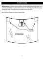
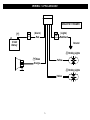
1
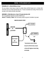
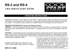
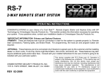
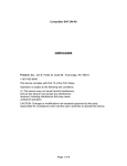
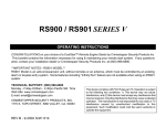
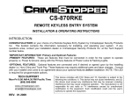
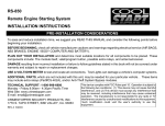
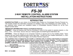
FS-89 FS-99 Alarm Combo System
INSTALLATION HANDBOOK:
INTRODUCTION
Congratulations on your choice of a Crimestopper combination alarm & remote engine starter with animated 3D
graphics, 2-Way Data Port for bypass module and Smart Phone Integration port.
This installation book is designed for the installer or individual with an existing understanding of
automotive electrical systems, along with the ability to test and connect wires for proper operation. To ease
installation, we suggest that you READ THIS MANUAL before beginning your installation. This book is
provided as a GENERAL GUIDELINE and the information contained herein may differ from your vehicle.
DISCLAIMER:
Crimestopper Security Products, Inc. and its vendors shall not be liable for any accident resulting from the
use of this product. This system is designed to be professionally installed into a vehicle in which all
systems and associated components are in perfect working condition.
TECHNICAL SUPPORT (800)-998-6880
Monday - Friday 8:00am - 4:30pm Pacific Time
Website: www.crimestopper.com
CRIMESTOPPER SECURITY PRODUCTS, INC.
1770 S. TAPO STREET
SIMI VALLEY, CA. 93063
REV
10.2012
This device complies with FCC Rules part 15. Operation is
subject to the following two conditions: 1) This device may not
cause interference, and (2) this device must accept any
interference that may be received, including interference that
may cause undesired operation. The manufacturer is not
responsible for any radio or TV interference caused by
unauthorized modification to this equipment. Such
modification could void the user's authority to operate the
equipment.
TABLE OF CONTENTS
Cautions & Warnings and Component Mounting ..…..………………………………………………………………….……3
Antenna Diagram…….………….…………………………....……………...……………………………………………..……4
5 Pin Connector Wiring – Siren and Lights.…………………....……………...……………………………………………5-6
18 Pin Connector Wiring…….…………………………....……………...…………………………………………..…..…7-12
Shock Sensor…………………………………….........……………...….………..…….……..…………...…………...……13
Power Door Locks.………………………….......………………….……..……………………………………………....14-16
1-Wire Door Locks…….…………………………………………………………………………………………...………17-19
Drivers Door Unlock…………………………..……….………………………………………………….………….…….20-21
Tach Reference…………………………………..…………………………………......…..…….……………...…...……….22
Option Table Programming…………………………………………………………………….…………………...……..23-25
Option Descriptions…..…………………....……………………………………......………………………….………….26-32
Remote Programming………….……………………..………………………………………...…………………...………...33
Alarm and Remote Start Diagnostics………………………………………………………………………………………...34
Main Module Connector Plugs……...………………………………………………………………………………………...35
Manual Transmission Mode…………………………………………………………………………………………………...36
System Wiring Diagram………………………...…………………………………………………………….……………37-38
PR
PRE-INSTALLATION CONSIDERATIONS
BEFORE BEGINNING, check all vehicle manufacturer cautions and warnings regarding electrical service (AIR BAGS, ABS
BRAKES, ENGINE / BODY COMPUTER AND BATTERY).
PLAN OUT YOUR INSTALLATION. You should pre-determine the location of the Control Module (Brain), Valet button,
LED, and Siren locations. This will save time and ease the installation process.
USE VOLT/OHM METER to test and locate all connections. Test Lights or Lighted Probes could possibly damage a
vehicle’s computer system or cause an airbag to deploy.
ADDITIONAL PARTS, that are not included with this unit, may be needed for your particular vehicle. These items may
include extra relays, Door Lock Interface Modules, or Transponder Override modules.
2
CAUTIONS & WARNINGS
DAMAGE RESULTING FROM IMPROPER INSTALLATION IS NOT COVERED UNDER WARRANTY!!
DO NOT remote start your vehicle in a closed garage. Make sure that the garage door is open or there is adequate
ventilation. Failure to observe this rule could result in injury or death from poisonous Carbon Monoxide fumes.
DO NOT ROUTE ANY WIRING THAT MAY BECOME ENTANGLED with the brake/gas pedals, steering column, or
any other moving parts in the vehicle.
REMOVE MAIN SYSTEM FUSE(S) before jump-starting the vehicle or charging the battery at high boost. DAMAGE
MAY OCCUR TO SYSTEM IF PROPER PRECAUTIONS ARE NOT OBSERVED.
DO NOT exceed the rated output current of any circuit on the Remote start module. Failure to observe this warning
will result in damage to the unit. Output currents are listed where applicable throughout this manual.
DO NOT extend the Remote start ignition harness length. Mount the module so that main harness reaches all
ignition switch wiring. Extending these wires could result in poor performance.
COMPONENT MOUNTING
CONTROL MODULE: The alarm control module should be mounted in a concealed location. DO NOT mount the
control unit in the engine compartment. Fasten the module to a bracket or wire harness using the cable ties
provided.
SIREN MOUNTING: Mount the siren under the hood to fender-well or other body surface with the open end facing
downward. Run the red siren wire through the firewall using a rubber grommet. Ground the black wire to the body
metal near the siren.
LED: Mount the Blue LED in a visible location on the dashboard or console.
ANTENNA TRANSCEIVER: Mount the antenna high up on the front windshield glass. Locate at least 1” away from
metal trim or window tint or film
OVERRIDE/PROGRAM/VALET BUTTON: Mount the Override/Program push-button in a hidden but accessible
location. This button is required for emergency disarm, programming, and valet mode.
3
ANTENNA DIAGRAM
ANTENNA MODULE: For optimum range and performance, the antenna/receiver module should be located high up
on the front windshield glass. For example: behind the rearview mirror. Note: Window tints or Films may decrease
the range of the system. The mounting surface for the antenna should be clean and dry.
Note: A call button is located on the antenna to activate the pager.
ANTENNA
LOCATIONS
WINDSHIELD
4
WIRING: 5-PIN Connector
Red: Alarm Power Source
5 Amp fuse Connect to 12 volt power source.
Red/Black: Parking Light Source
10 Amp Fuse Connects to 12 volts or ground depending on parking light circuit in vehicle
Orange: (+) Siren Output
Connect brown wire to siren red wire. Connect black wire of siren to chassis ground (body metal).
Yellow: Parking Lights – Dual 5 Amp Relay Output
(+)
12 Volt
Battery
5 AMP
FUSE
10 AMP
FUSE
Red
(Alarm)
POSITIVE TRIGGER
Red/black
(Lights)
(+) Parking Lights
(+) Siren
Yellow
Orange
(+) Parking Lights
Yellow
5
WIRING: 5-PIN Connector
NEGATIVE TRIGGER
(+)
5 AMP
FUSE
(Alarm)
Red
10 AMP
FUSE
(Lights)
Red/black
12 Volt
Battery
Ground
(-) Parking Lights
(+) Siren
Yellow
Orange
(-) Parking Lights
Yellow
6
WIRING: 18-PIN Connector
BLUE/ORANGE: (-) 500mA Starter 2 Output
Some vehicles require a 2nd start wire for remote start.
BLUE/ORANGE
CONNECT TO IGN
85
86
30
87
+
BATTERY
STARTER
ORANGE: (-) 500mA Starter Kill / Anti-Grind Output
This wire should be connected to the Black wire of the pre-wired relay socket for the starter disable. Connect the
Red wire of the relay socket to the Ignition switched wire on the vehicle. Cut the vehicle starter wire and connect
each half to the Yellow and Blue wires on the relay socket as shown. This output also turns on with remote start to
function as an “Anti Grind” wire to prevent the starter from grinding if you get in your car and turn the key too far
after it was remote started. See starter disable diagram on next page.
IGNITION SWITCHED
"ON" & HOT THROUGH
CRANKING
IGN. SWITCHED
STARTER WIRE
CONNECT TO
ORANGE WIRE
OF ALARM
PRE-WIRED
STARTER DISABLE
RELAY & SOCKET
CUT
BLACK
STARTER
RED
YELLOW
BLUE
START OUTPUT
FROM ALARM
6-PIN HARNESS
BROWN
STARTER DISABLE:
7
MAKE CERTAIN TO
CONNECT BROWN
WIRE TO STARTER
MOTOR SIDE!!!
WIRING: 18-PIN Connector Cont.
ORANGE/BLACK: (-) 500mA OEM Disarm Output
This wire provides a Ground pulse to disarm the vehicles Factory Anti-Theft System prior to a Remote Start.
Connect this wire to the vehicles' anti-theft disarm wire. This wire is sometimes found coming off the Driver's door
key switch or at the Factory Anti-theft control module.
GREEN/RED: (-) 500mA Remote Aux. Output 1 (Programmable Option #10)
This is a programmable output that can operate 4 different ways.
Channel 1 = Trunk Pop - Default. This is a momentary output as long as the Trunk Button 3 is pressed.
NEGATIVE AUXILARY OUTPUT
+12V CONSTANT
GREEN/RED
OR
(-) AUX OUTPUT
85
86
30
87
+12V CONSTANT
OR *
Trunk Soleniod
-ORAux Function
* Test activation circuit in vehicle.
Connect to+12V for Positive circuits
or Ground for Negative circuits. Relay
not included.
8
WIRING: 18-PIN Connector Cont.
BLUE/WHITE: (-) 500mA Remote Aux. Output 2 (Programmable Option #11)
This is a programmable output that can operate 4 different ways.
1. Channel 2 = 2nd Unlock Hold 2 Sec. - Default. Hold Unlock Button for 2 seconds to unlock passenger doors.
2. Channel 2 = 2nd Unlock Double Press. Press Unlock button 2 times to unlock passenger doors.
3. Channel 2 = Momentary Hold. This is a momentary output as long as the remote button is pressed.
4. Channel 2 = 30 Second Timer.
BLACK/WHITE: (-) 500mA Remote Aux. Output 3 (Programmable Option #12)
This is a programmable output that can operate 4 different ways.
Channel 3 = Dome Light - Default. For Dome light Supervision with unlock.
Negative Dome Light System: Connects to terminal 85 of a relay. Connect terminal 86 to +12V Constant.
Connect terminal 87 to Chassis Ground. Connect Terminal 30 to the Negative dome light activation circuit.
Positive Dome Light System: Connects to terminal 85 of a relay. Connect terminals 86 & 87 to +12V Constant.
Connect terminal 30 to the Positive dome light activation circuit.
BROWN/WHITE: (-) 500mA Remote Aux. Output 4 (Programmable Option #13)
This is a programmable output that can operate 4 different ways.
Channel 4 = Horn Honk - Default. Connect to the Negative Horn Trigger wire usually located near the steering
column. If the vehicle horn circuit requires +12 volts, a relay is required. RELAY WIRING: Connect the Brown/White
wire to terminal 85, connect relay terminals 86 and 87 to +12V constant power. Connect terminal 30 of the relay to
the +12V positive device/circuit to be activated.
ORANGE WHITE: (-) 500mA Remote Aux. Output 5 – ACCESSORY or OEM REARM
(Programmable Option #14)
This is a programmable output that can operate 4 different ways.
Channel 5 = Accessory - Default. Controls 2nd Accessory Output for Remote Start. RELAY WIRING: Connect the
Orange/White wire to terminal 85, connect relay terminals 86 and 87 to +12V constant power. Connect terminal 30
of the relay to the 2nd Accessory wire of the vehicle. Channel # 5 can be programmed for OEM REARM. This
option provides a ground pulse to rearm the vehicles' FACTORY anti-theft system after a timed-out or aborted
remote start. Connect this wire to the vehicles' anti-theft rearm wire or to the door pin circuit depending on your
requirements. This wire may be needed to pulse the door pin circuit on vehicles with retained accessory power.
9
WIRING: 18-PIN Connector Cont.
BLUE/BLACK: (-) 500mA Remote Aux. Output 6 (Programmable Option #15)
This is a programmable output that can operate 4 different ways.
Channel 6 = Ignition Run - Default. This is used for Remote Start - Ground when Running. This wire functions as
a Negative IGNITION OUTPUT (Ground while Remote Starting) for use when connecting factory Security Bypass
modules or when an additional external Ignition Relay is required for your installation.
BLACK: CHASSIC GROUND
Connect to body metal of the vehicle using a sheet metal screw and a star washer to ensure a good ground. Keep
the Ground wire short. Scrape away paint or debris from ground location.
GRAY: (-) Hood Trigger and Temperature Sensor Input – Zone # 6
Input trigger for a grounding hood pin switch. Connect to an existing hood pin switch that read ground when open. If
no existing switches are available, install new pin switches if desired. Note: DO NOT mount new pin switches in
water pathways.
Locate Temperature Sensor inside vehicle out of direct sunlight. The Temperature Sensor connects to Gray Hood
switch input as shown.
Temperature Sensor
Alarm Plug
(-) Hood
Switch
Gray Wire
10
WIRING: 18-PIN Connector Cont.
VIOLET: (+) Door Trigger Input – Zone # 5
Same as the GREEN wire below except this wire is used for vehicles that show a positive voltage (+12 volts) when
the door is open and a ground when doors are closed as in many Ford, Lincoln, and Mercury vehicles.
GREEN: (-) Door Trigger Input – Zone # 5
Identify the wire that reads ground when any door is open and 12 volts when all doors are closed. Some vehicles
may have isolated door triggers. In this case you may need to run additional wires from other doors or go directly to
the wire that triggers the vehicle’s interior dome light. Sometimes newer vehicles contain a separate body control
module (BCM) where the door trigger circuit can be located. Most vehicles will NOT require the use of BOTH Green
and Violet door trigger wires.
BLUE: (-) Trunk Trigger Input – Zone # 4
Input trigger for a grounding trunk pin switch. Connect to existing trunk pin switch that read ground when open. If no
existing switches are available, install new pin switch if desired. Note: DO NOT mount new pin switches in water
pathways.
PINK: (-) Start Activation or (+ or -) Diesel Glow Plug
The function of this wire is programmable option # 18.
• (-) Start Activation Input: This wire allows an outside source or accessory to activate a Remote Start. A
momentary ground pulse on this wire will trigger a remote start. Default
• (+ or -) Glow Plug circuit using the Pink input wire. When this wire is used, the system will wait until light turns
off before engaging the starter.
• Fixed 15 second delay (pink wire not used). Most new vehicles have a computer controlled wait to start circuit.
There is no wait to start wire, only an indicator light on the dash that is not accessible. These vehicles require
a fixed time delay for remote starting.
WHIT/RED: TACH INPUT
When installing this system in TACH REFERENCE mode, this wire must be connected to a valid source of AC
voltage. This wire allows the unit to sense the engine running. This is the most reliable method for remote starting.
See Tach Reference Section on Page 22 for more information.
11
WIRING: 18-PIN Connector Cont.
BRAKE RESET:
There are 2 Brake reset input wires, (+) White and (-) White/black. The White is (+) for the brake pedal. The
White/black is for (-) hand brake or emergency brake on manual transmission vehicles. Option # 26 must be
activated for the White/black wire to function.
White: (+12V) Brake Pedal Reset
Connect the White wire to the side of brake pedal switch that shows +12 volts ONLY when pedal is depressed. This
will turn off the remote start if someone attempts to drive the car without the keys or if the Ignition key is not turned
on all the way.
WHITE/BLACK: (-) Hand Brake Reset for Manual Transmission
Option #26 – Manual Transmission must be set for the Hand Brake Reset wire to work. Connect the White/black
wire to the side of the hand brake that shows (-) ONLY when the hand brake is set. In this mode, the remote start
will turn off when the hand brake is released. A Databus module can also supply the Hand Brake status signal
on most late model vehicles. Please check Databus module features before connecting hand brake wire.
NOTE : May need to diode isolate hand brake to keep feedback from vehicle.
12
WIRING: 4-PIN Shock Sensor (22 Gauge wires)
SHOCK SENSOR: There are 2 sensor ports (zone 2 and 3) on the alarm module. The sensor supplied with this
system does not require any additional wiring. Simply mount the sensor in a suitable location. It can be tie wrapped
to a cable harness or mounted to a plastic panel. Plug sensor into Sensor Plug # 1 for zone 2, and adjust the
sensitivity. There are 2 LED’s on the shock sensor to assist you in adjusting sensitivity. The Green LED indicates
the “Warn Away” level and the Red LED indicates a full alarm shock sensor violation.
The adjustment knob next to Red LED is for trigger.
The adjustment knob next to Green LED is for Pre-Warning.
Sensor Plug # 2
(Zone # 3)
Antenna Plug
Sensor Plug # 1
(Zone # 2)
Valet Plug
Data Plug (Bypass Module)
LED Plug
Smart Phone
Data Plug
MAIN MODULE
The Sensor Plug #2 is zone 3 for an optional sensor.
13
WIRING: 2-PIN LED / 2-PIN Program-Valet Button (22 gauge wires)
Mount LED in a visible location on the Dash or Console. Connect the small 2-pin plug from the LED to the control
module. Note: Connectors are designed so that they will only plug into their appropriate slots.
Mount the Valet/Program/Override button in a suitable location. Connect the 2-pin plug from the Switch to the
control module. Note: Connectors are designed so that they will only plug into their appropriate slots.
POWER DOOR LOCKS: WIRING & SYSTEM TYPES
DETERMINING DOOR LOCK TYPE:
We recommend determining the type of locking system the vehicle has before connecting any wires. Most new
vehicles have data controlled door locks and require a data module to interface with the vehicle computer. Please
go to the Databus section of the Crimestopper website. Select the type of data module (Fortin or ADS) and it will
take you to a vehicle fit guide to determine the best solution for your vehicle. Incorrect connection may result in
damage to the alarm and/or vehicle locking system. The system has 2 Built-In relays to interface with most door lock
systems. The following door lock information is provided as a guide. Your vehicle may differ.
LOCK RELAY: (On-Board Relay)
WHITE: Normally Closed (Terminal 87A On-board Lock Relay)
GREEN: LOCK Output (Terminal 30 On-board Lock Relay)
VIOLET/BLACK (Fused 10A): Normally Open (Terminal 87 On-board Lock Relay)
UNLOCK (On-Board Relay):
BROWN: Normally Closed (Terminal 87A On-board Unlock Relay)
BLUE: UNLOCK Output (Terminal 30 On-board Unlock Relay)
VIOLET (Fused 10A): Normally Open (Terminal 87 On-board Unlock Relay)
14
DOOR LOCK WIRING
Negative Trigger (-): Many Imports; Late model Ford & General Motors
Negative trigger door lock systems send a Negative (Ground) pulse to existing factory relays to lock and unlock the
vehicle doors.
Positive Trigger (+): Many General Motors; Chrysler / Dodge / Plymouth
Positive trigger door lock systems send a Positive (12V) pulse to existing factory relays to lock and unlock the
vehicle doors.
NEGATIVE TRIGGER
POSITIVE TRIGGER
Blue
Brown
White
(No Connection)
Green
Violet
Blue
White
Brown
(No Connection)
Green
Violet/Black
Violet
Violet/Black
+
Ground
12 Volts
U
L
Factory
Door
Lock
Module
L
U
+
Ground
12 Volts
15
Factory
Door
Lock
Module
DOOR LOCK WIRING
Reverse Polarity: Many Ford/Lincoln/Mercury/Dodge/Chrysler/Plymouth and early 90’s GM Trucks
Reverse Polarity systems use no relays, but instead the door lock/unlock motors are controlled directly from the lock
and unlock switches in the door. The lock and unlock wires rest at Negative Ground when not in use. When the
lock or unlock button is pressed, one of the circuits is “Lifted” and replaced with +12V causing a lock or unlock to
occur.
5 WIRE REVERSE POLARITY
Brown
AFTER MARKET DOOR LOCKS
Blue
White
Brown
Green
Violet
Blue
Green
White
Violet/Black
Violet
Violet/Black
+
12 Volts
(Fused)
+
Ground
U
CUT
L
Factory
Door
Lock
Module
+
12 Volts
16
12 Volts
(Fused)
1-WIRE RESISTOR DOOR LOCKS
Single Wire (Dual Voltage): Late model Chrysler/Dodge/Plymouth Vehicles, some 2000-UP GM Cars
Dual Voltage systems have lock/unlock switches that send varying levels of Positive voltage OR Negative ground
current to the SAME wire for both lock and unlock. When the vehicle’s Body Computer Module (BCM) or door lock
module senses different voltages on this wire, the system will either lock or unlock. Single wire door lock systems
require resistors.
1. Locate your vehicle in the chart below to determine the proper resistor value(s), wire color and location. Note:
the information is intended as a guide and your vehicle may differ.
2. See chart below for installation.
Polarity
Lock
Resistor
Unlock
Resistor
Wire Color
Location
Buick Rendezvous 2001-UP
Chevy Malibu 2001-UP
Chevy Impala, Monte Carlo 2000-UP
Neg.
Neg.
Neg.
470 Ohms
None
470 Ohms
None
1.5K Ohms
None
Red / Black
White
Orange / Black
Chrysler 300M, Concord, Intrepid, LHS, 1998-UP
Pos.
2.7K Ohms
620 Ohms
White / Green
Chrysler 300C
Chrysler Pacifica
Chrysler PT Cruiser 2001-2006
Chrysler PT Cruiser 2001-2006 with alarm
Neg.
Neg.
Neg.
Neg.
330 Ohm
1.8K Ohm
None
2.7K Ohms
100 Ohm
750 Ohm
1.5K Ohms
7.5K Ohms
Chrysler PT Cruiser 2007-UP
Neg.
None
250 Ohms
Pos.
900 Ohm
430 Ohm
Violet / Green
Violet / Blue
White / Green
White / Green
LT Green/
DK Green
LT Green/
Orange
BCM at Console
Driver’s Kickpanel
Driver’s Kickpanel
BCM at Driver’s
Kickpanel
Driver’s Kickpanel
Inside Driver’s Door
Driver’s Kickpanel
Driver’s Kickpanel
Pos.
620 Ohms
2.7K Ohms
White / Green
Pos.
620 Ohms
2.7K Ohms
White / Green
Pos.
750 Ohms
1.8K Ohms
LT Green/
Orange
Pos.
1780 Ohms
730K Ohms
White / Green
Pos.
1780 Ohms
730K Ohms
Neg.
Neg.
Neg.
1.5K Ohms
4020 Ohms
5.2K Ohms
250 Ohms
665 Ohms
2K Ohms
Vehicle
Chrysler 1995-00 Cirrus, Stratus, Sebring Cont, with
alarm
Chrysler 1995-00 Cirrus, Stratus, Sebring Cont
without alarm
Chrysler Sebring and Stratus coupe 2001 without
alarm
Chrysler Sebring and Stratus coupe 2001 with
alarm
Chrysler Sebring and Stratus sedan 2001 without
alarm
Chrysler Sebring and Stratus sedan 2001 with
alarm
Chrysler Town & Country 1996-2000 without alarm
Chrysler Town & Country 1996-2000 with alarm
Chrysler Town & Country 2001-06 without alarm
17
LT Green/
Orange
White / Green
White / Green
Violet / Green
Driver’s Kickpanel
Driver’s Kickpanel
BCM at Driver’s
Kickpanel
BCM at Driver’s
Kickpanel
BCM at Driver’s
Kickpanel
BCM at Driver’s
Kickpanel
BCM at Driver’s
Kickpanel
Driver’s Kickpanel
Driver’s Kickpanel
BCM at Firewall
Polarity
Lock
Resistor
Unlock
Resistor
Chrysler Town & Country 2001-06 with alarm
Chrysler Voyager 2001-2006
Dodge Caravan 1996-2000 without alarm
Dodge Caravan 1996-2000 with alarm
Dodge Caravan 2001-06 without alarm
Dodge Caravan 2001-06 with alarm
Dodge Charger
Neg.
Neg.
Neg.
Neg.
Neg.
Neg.
Neg.
2K Ohms
5.3K Ohms
1.5K Ohms
4020 Ohms
5.2K Ohms
2K Ohms
330 Ohm
5.2K Ohms
2K Ohms
250 Ohms
665 Ohms
2K Ohms
5.2K Ohms
100 Ohm
Dodge Durango 2000
Neg.
620 Ohms
1.5K Ohms
Dodge Durango 2001-02 without alarm
Dodge Durango 2001-02 with alarm
Dodge Magnum
Dodge Neon 2000-UP without alarm
Dodge Neon 2000-UP with alarm
Dodge Ram Pickup 2002 without alarm
Neg.
Neg.
Neg.
Neg.
Neg.
Neg.
815 Ohms
620 Ohms
330 Ohm
None
2.7K Ohms
815 Ohms
315 Ohms
1.5K Ohms
100 Ohm
1.5K Ohms
750 Ohms
315 Ohms
Dodge Ram Pickup 2002 with alarm
Neg.
2K Ohms
480 Ohms
Dodge Ram Pickup 2004
Ford Probe 1990-97
Ford Escape 2001-UP
Jeep Liberty 2002-UP
Mazda 323 1995
Mazda 626 1998-01
Mazda Millennia 1995-99
Mazda Millennia 2001
Mazda MPV 2000 without alarm
Mazda MPV 2000 with alarm
Mazda Protégé 1998-03
Mazda Tribute 2001-UP
Mercedes Benz SLK230 98-01
Oldsmobile Alero 1999-UP
Plymouth Breeze 1996-00
Plymouth Voyager 1996-2000 without alarm
Plymouth Voyager 1996-2000 with alarm
Pontiac Aztec 2001-UP
Pontiac Grand Am 1999-UP
Neg.
Pos.
Neg.
Neg.
Neg.
Neg.
Neg.
Neg.
Neg.
Neg.
Neg.
Neg.
Neg.
Neg.
Pos.
Neg.
Neg.
Neg.
Neg.
880 Ohms
None
1K Ohm
1.4K Ohm
1K Ohms
1K Ohms
1K Ohms
1K Ohms
2.2K Ohms
2.2K Ohms
1K Ohms
1K Ohm
526 Ohms
None
620 Ohms
1.5K Ohms
4020 Ohms
470 Ohms
None
280 Ohms
4.7K
None
440 Ohm
None
None
None
None
None
None
None
None
None
1.5K Ohms
2.7K Ohms
249 Ohms
665 Ohms
None
1.5K Ohms
Vehicle
18
Wire Color
Location
Violet / Blue
White / Green
White / Green
White / Green
Violet / Green
Violet / Blue
Violet / Green
LT Green
/Orange
White / Green
White / Orange
Violet / Green
LT Green
LT Green
White / Green
LT Green/
Orange
Violet / LT Blue
Green / Black
Pink / White
Pink / Violet
White / Blue
Yellow / Green
Red / Black
White/Blue
DK Green
LT Green
Green / Red
Pink / White
White / Green
White
White / Green
White / Green
White / Green
Red / Black
White
BCM at Firewall
Driver’s Kickpanel
Driver’s Kickpanel
Driver’s Kickpanel
BCM at Firewall
BCM at Firewall
Driver’s Kickpanel
Driver’s Kickpanel
Driver’s Kickpanel
Driver’s Kickpanel
Driver’s Kickpanel
Driver’s Kickpanel
Driver’s Kickpanel
Driver’s Kickpanel
Driver’s Kickpanel
Driver’s Kickpanel
Driver’s Kickpanel
Driver’s Kickpanel
Driver’s Kickpanel
Driver’s Kickpanel
Driver’s Kickpanel
Driver’s Kickpanel
Driver’s Kickpanel
Pass Kickpanel
Pass Kickpanel
Driver’s Kickpanel
Driver’s Kickpanel
Driver’s Kickpanel
Driver’s Kickpanel
Driver’s Kickpanel
Driver’s Kickpanel
Driver’s Kickpanel
BCM at Console
Driver’s Kickpanel
1-WIRE RESISTOR DOOR LOCKS
Blue
Brown
White
(No Connection)
Green
Violet
Violet/Black
¼ Watt
Resistors
Ground
Factory
Door
Lock
Module
L
U
Ground
19
SEPARATE DRIVER’S DOOR UNLOCK WIRING
NEGATIVE TRIGGER
CH 2 Output
Program Option #10
2nd Unlock
(-) Blue/white
+
Violet
12 Volts
Brown
Blue
White
Green
Violet/Black
Factory
Door
Lock
Module
L
U
Ground
CUT
Unlock Wire
20
SEPARATE DRIVER’S DOOR UNLOCK WIRING
REVERSE POLARITY
Relay
CH 2 Output
Program Option #10
2nd Unlock
(-) Blue/white
86
85
87
87A
Brown
Blue
White
Green
Violet/Black
Violet
+
12 Volts
L
CUT
U
+
CUT
CUT
Unlock Wire
21
30
+
12 Volts
ENGINE MONITORING and TACH REFERENCE MODE
This system has 4 methods of monitoring the engine running. Option #1 controls how the system monitors the
engine running.
1. The Default is Tachless Low Level. When vehicle is remote started, the battery voltage rate will go up
because the Alternator starts working. At Low Level, the battery voltage will need about 0.1 volt increase for
remote start success.
2. Tachless High Level - When vehicle is remote started, battery voltage rate will go up because the Alternator
starts working. At High Level, the battery voltage will need about 0.4V increase for remote start success.
3. Tach Reference Mode – Monitors Engine R.P.M. - Most reliable method, see Tach programming below.
4. Hybrid Mode – For electric motors that are computer controlled. This provides a 2 second crank output to
activate the start sequence on Hybrid vehicle. Don’t use on vehicles with gas or diesel engine, doesn’t monitor
stalled engine or low battery voltage.
Tach Reference Mode: Provides reliable remote starting performance though engine speed sensing. When using
Tach Reference Mode, the WHITE/RED wire is used for Tach signal [Engine RPM] input. Most modern engines
include various points where the Engine Speed [Tach] or A/C signal may be obtained. Tach Signal examples: Fuel
Injection Solenoids, Negative (-) side of ignition coil, at the Distributor or Ignition Control Module, Coil Pack, Engine
Computer, or Crankshaft Sensor. Sometimes an Alternator Stator pin can be used. These Tach Signal locations
mentioned are provided as a guide, your vehicle may differ. Some locations will NOT be a good location for Tach
source due to RF noise or Computer Data.
Note: When using a Databus module for Tach signal, don’t connect up the Tach wire. This will create a
conflict. The System can only use one Tach source.
TACH PROGRAMMING - Automatically sets option # 1 for Tach with 3.6 second maximum cranking time.
1. Turn On ignition switch.
2. Press Valet / Override button 6 times. After a few seconds the unit will flash the lights and chirp the siren 6
times to confirm.
3. Press Valet / Override button again 1 time. The siren chirps 1 time.
4. Start the vehicle with the ignition key. While the engine is running, the parking will flash to indicate a good
Tach source. If they don’t flash, please check tachometer wire connection.
5. To Record RPM, press button 1 on transmitter. System will chirp once to confirm. The Remote control will
confirm Tach program. The lights stop flashing.
22
PROGRAMMABLE OPTIONS
You can program multiple options in one session if you start with the lowest option and continue on to higher options
without repeating steps #1-3 below. For example, you can follow the programming steps to change an Option by
pressing button 1 to 4 on the remote, then you can continue pressing the program button additional times to get to a
high number option and change the setting without having to repeat Steps 1-5. You can only go from low to higher
option numbers in one session.
To Engage Option Programming:
1. Turn Ignition Key to the ON position
2. Press Program / Valet button 5 times, after a few seconds the unit will flash the lights and Siren Chirps 5 times.
3. Push the valet/program button [again] the number of times that corresponds to the option number desired (1 thru
30). You must get a light flash and chirp after each button press.
4. When you reach the desired programming level, Press button #1, #2 #3 or #4 to change the option level. The
siren and horn will confirm with 1-4 chirps. The remote control will confirm program option selection on top
right corner of display. Example option #6 button 4 shows *06--4
5. Turn Ignition OFF and check for changed features.
Note: The Program Mode Exits automatically after 20 seconds (lights flash 4 times on exit).
23
PROGRAMMABLE OPTIONS
#
Option
Description
TX Button #1
Factory Default
TX Button #2
(2 Chirps)
TX Button #3
(3 Chirps)
TX Button #4
(4 Chirps)
1
Engine Monitoring
Tachless Low Level
Tachless High Level
Engine R.P.M. (Tach)
Hybrid Mode
2
Auto lock with
Ignition
Ignition ON = Lock
Ignition OFF = Unlock
OFF
3
Open Door
Warning
45 Sec. Delay
30 Sec. Delay
15 Sec. Delay
0 Sec. Delay
4
Horn Honk Output
Arm/Disarm/
Warning/Trigger
Warning and Trigger
Trigger Only
5
Auto Rearm /
Active Rearm
OFF
Auto Rearm with Lock
Auto Rearm without Lock
Active Rearm ON
6
Passive Arming
OFF
Passive Arm with Lock
Passive Arm without Lock
OFF with Reminder
Chirps
7
Data Port Protocol
OFA Series
8
Siren Output
Warning and Trigger
Trigger Only
9
Pink/white Wire
SL Series
Arm/Disarm/
Warning/Trigger
IGN 2
ACC 2
Start 2
10
Channel 1 Output
Green/red wire
Trunk Pop
(Momentary Hold)
30 Second Timer
Latch On/Off
Latch On/Off with
Ignition Reset
11
Channel 2 Output
Blue/white wire
2nd Unlock Hold
Button 2 Sec.
2nd Unlock Double
Press
Momentary Hold
30 Second Timer
12
Channel 3 Output
Black/white wire
Dome Light
8 Sec. Pulse with Arm
for window roll up
Momentary Hold
30 Second Timer
13
Channel 4 Output
Brown/white wire
Horn Honk
8 Sec. Pulse with Arm
for window roll up
Momentary Hold
30 Second Timer
14
Channel 5 Output
Orange/white wire
Accessory
OEM Rearm
Latch On/Off with
Ignition Reset
Momentary Hold
15
Channel 6 Output
Blue/black wire
Ignition Run
(Ground when
Running)
Latch On/Off
Latch On/Off with
Ignition Reset
Momentary Hold
24
PROGRAMMABLE OPTIONS
16
17
18
19
Disarm with Trunk
Pop
Park Lights On
with Disarm
Pink wire Selection
Maximum Crank
Time
OFF
ON
ON (30 sec timer)
OFF
(-) Start Activation
15 Seconds
(+) Glow Plug
(-) Glow Plug
0.8 Seconds
(-) 0.1 Seconds
(+) 0.1 Seconds
(+) 0.4 Seconds
20
Door Locks
0.8 Sec. Lock / Unlock
3.5 Sec. Lock / Unlock
Double Unlock
“Wake Up" pulse on
Unlock (0.8 sec. +12V
to IGN & (-) Run)
21
Remote Start Run
Time
20 Minutes
15 Minutes
10 Minutes
5 Minutes
22
3 Chirps on
Remote Start
Siren
OFF
Horn
Siren & Horn
23
24
Turbo Timer Mode
Idle Down
OFF
15 Minutes
1 Minute
30 Minutes
6 Minutes
Infinity Run
25
Lock with Remote
Start
Lock with Remote Start
OFF
3 Minutes
45 Minutes
Lock with Remote
Start - Lock / Arm OEM
Alarm with Remote
Start Abort
26
Transmission Type
Automatic Transmission
Manual Transmission
with Remote Control
and Hand Brake
27
Carjack Protection
OFF
ON
28
29
30
Arm & Disarm thru
OEM Remote
(Data Mode Only)
Unlock before
Remote Start
Factory Defaults
OFF
Arm & Disarm
OFF
ON
Manual Transmission
with Hand Brake Set
Lock / Arm OEM
Alarm with Abort Only
Manual Transmission
with Hand Brake Set
(Auto shut down with
last door closed 2 sec)
Arm / Disarm / Start
(3 Press OEM Lock =
Remote Start)
Press Button 1 to Reset All Options to Default
NOTE: The 2-Way remote control will confirm program option selection on top right corner of display.
Example option #6 button 4 shows *06--4
25
PROGRAMMABLE OPTION DESCRIPTIONS
1. ENGINE MONITORING:
This option controls how the system monitors the engine running. You can program for Tachless mode that monitors
battery voltage, Tach mode in which the unit uses a Tach signal (RPM) or for Timed Crank as an alternative. There
are 4 choices for this option:
1. Tachless Low Level - Default. When vehicle is remote started, the battery voltage rate will go up because
the Alternator starts working. At Low Level, the battery voltage will need about 0.1 volt increase for remote
start success.
2. Tachless High Level - When vehicle is remote started, battery voltage rate will go up because the Alternator
starts working. At High Level, the battery voltage will need about 0.4V increase for remote start success.
3. Engine R.P.M. (Tach) - Most reliable method. Tach must be programmed for this option to work.
4. Hybrid Mode – For electric motors that are computer controlled. This provides a 3.6 second crank output to
activate the start sequence on Hybrid vehicle. Don’t use on vehicles with gas or diesel engine, doesn’t monitor
engine running or low battery voltage. Option #19 allows you to shorten starter crank time if necessary.
2. AUTO LOCK with IGNITION:
This feature controls whether the doors will automatically lock when the ignition is turned on and unlock when the
ignition is turned off. Some vehicles already have this feature from the factory you should turn off this option. Doors
will not lock if they are open to prevent locking the keys in. There are 4 choices:
1. Ignition ON = Lock, Ignition OFF = Unlock - Default.
2. OFF = No Lock or Unlock with ignition.
3. OPEN DOOR WARNING:
This setting changes the delay time in which the alarm system begins to monitor the Door circuit. This option can
prevent the alarm from giving warning chirps on vehicles with a delayed dome light. You can set the time delay for
45, 30, 15 or 0 Seconds. The Default = 45 Seconds.
4. HORN HONK OUTPUT:
This option controls whether the Siren and Car Horns Chirp with normal Arm and Disarm. There are 3 choices:
1. Horns Chirp with Arm / Disarm / Warning and Honk with Alarm Trigger - Default.
2. Warning Chirp and Honk with Alarm Trigger (no arm / disarm chirps).
3. Honk with Alarm Trigger only.
26
PROGRAMMABLE OPTIONS Cont.
5. AUTO REARM / ACTICE REARM:
The option controls whether the alarm system rearms 30 seconds after disarm. This is handy if the vehicle is
accidentally disarmed without your knowledge. There are 4 choices:
1. OFF = Default - No Automatic Rearm in Passive or Active Mode.
2. Auto Rearm with Lock - The alarm system will always rearm and lock the doors after disarm unless the ignition
is turned on. This applies to Passive and Active Mode. This choice is best for security but increases the risk of
locking the keys in the ignition.
3. Auto Rearm without Lock - The alarm system will always rearm and without locking the doors after disarm
unless the ignition is turned on. This applies to Passive and Active Mode.
4. Active Rearm ON – The system will Rearm and lock the doors unless the door, hood or trunk is opened.
6. PASSIVE ARMING:
This option is used to automatic arm the alarm system 30 seconds after the ignition is tuned off and the last door is
closed. If a door is reopened during the 30 second countdown, the system will wait and begin the countdown again
after the door is closed. There are 4 choices:
1. OFF = Default – No Passive Arming.
2. Passive Arm with Lock – The system Locks the doors with Passive Arm. This choice is best for security but
increases the risk of locking the keys in the ignition.
3. Passive Arm without Lock – The system Passive Arms without locking the doors.
4. OFF with Arming Reminder Chirps – Passive Arm OFF with the Arming Reminder Chirps 20 seconds after
closing last door.
7. DATA PPORT PROTOCOL:
This option controls the Data Port Protocol for OFA Series modules or SL Series modules. The default is set for SL
Series Protocol. This option has no effect on conventional wiring of Bypass modules. Both OFA series and SL series
are 2-Way Protocol.
Note: When using a Databus module please check On-Line for latest available software update and
installation guide.
27
PROGRAMMABLE OPTIONS Cont.
8. SIREN OUTPUT:
This option controls whether the Siren Chirps with Arm / Disarm and Warning. There are 3 choices:
1. Siren Chirps with Arm / Disarm / Warning and Alarm Trigger - Default.
2. Warning Chirps and Alarm Trigger (no arm / disarm chirps).
3. Siren Activates with Alarm Trigger only.
9. PINK / WHITE WIRE SELECTION:
This option controls the Pink / White wire function.
1. Pink / White = Ignition 2 - Default.
2. Pink / White = Accessory 2
3. Pink / White = Start 2
10. CHANNEL 1 OUTPUT (Green/red wire):
This option controls the function of Green/red wire.
1. Channel 1 = Trunk Pop - Default. This is a momentary output as long as the remote button is pressed.
2. Channel 1 = 30 Second timer.
3. Channel 1 = Latch ON / OFF.
4. Channel 1 = Latch ON / OFF with ignition reset.
11. CHANNEL 2 OUTPUT (Blue/white wire):
This option controls the function of the Blue/white wire.
5. Channel 2 = 2nd Unlock Hold 2 Sec. - Default. Hold Unlock Button for 2 seconds to unlock passenger doors.
6. Channel 2 = 2nd Unlock Double Press. Press Unlock button 2 times to unlock passenger doors.
7. Channel 2 = Momentary Hold. This is a momentary output as long as the remote button is pressed.
8. Channel 2 = 30 Second Timer.
12. CHANNEL 3 OUTPUT (Black/white wire):
This option controls the function of the Black/white wire.
1. Channel 3 = Dome Light - Default. For 30 second Dome light Supervision with unlock.
2. Channel 3 = 8 Second Pulse with Arm. For activating a window roll up module.
3. Channel 3 = Momentary Hold. This is a momentary output as long as the remote button is pressed.
4. Channel 3 = 30 Second Timer.
28
PROGRAMMABLE OPTIONS Cont.
13. CHANNEL 4 OUTPUT (Brown/white):
This option controls the function of the Brown/white wire.
1. Channel 4 = Horn Honk - Default. For Horn Honk output.
2. Channel 4 = 8 Second Pulse with Arm. For activating a window roll up module.
3. Channel 4 = Momentary Hold. This is a momentary output as long as the remote button is pressed.
4. Channel 4 = 30 Second Timer.
14. CHANNEL 5 OUTPUT (Orange/white wire):
1. Channel 5 = Accessory - Default. Controls 2nd Accessory Output for Remote Start.
2. Channel 5 = OEM Rearm. For arming a factory alarm system.
3. Channel 5 = Latch ON / OFF with ignition reset.
4. Channel 5 = Momentary Hold. This is a momentary output as long as the remote button is pressed.
15. CHANNEL 6 OUTPUT (Blue/black wire):
This option controls the function of the Blue/black wire.
1. Channel 6 = Ignition Run - Default. This is used for Remote Start Ground when Running.
2. Channel 6 = Latch ON / OFF.
3. Channel 6 = Latch ON / OFF with ignition reset.
4. Channel 6 = Momentary Hold. This is a momentary output as long as the remote button is pressed.
16. DISARM WITH TRUNK POP (Aux 1 Green/red wire):
Default = OFF. Controls whether the system will or will not DISARM when the trunk pop or AUX. feature is used.
When the feature is turned on the unit will DISARM when opening trunk or using an auxiliary device controlled by
the Green/Red wire.
17. PARK LIGHTS ON 30 SECONDS WITH DISARM:
Default = ON. Keeps parking lights on when system is disarmed to assist in locating and providing illumination near
your vehicle when approaching at night for safety. The parking light also turns off with ignition on.
29
PROGRAMMABLE OPTIONS Cont.
18. PINK WIRE SELECTION:
This option is used to change the function of the Pink wire.
There are 4 choices for this option:
1. (-) Start Activation - Default. This wire allows an outside source or accessory to activate a Remote Start. A
momentary ground pulse on this wire will trigger a remote start.
2. 15 Second Delay - Provides a solution for diesel vehicles without having to connect to the Glow Plug “Wait to
Start” input. This may be due to a variety of reasons for example: If your vehicle does not have a “Wait to Start
Circuit” or you cannot locate and identify the circuit.
3. (+) Glow Plug – Pink Input Wire must be connected to a positive “Wait to Start Light” (120 second max delay).
4. (-) Glow Plug – Pink Input Wire must be connected to a negative “Wait to Start Light” (120 second max delay).
19. MINIMUN STARTER CRANK TIME: Default = 0.8 seconds
This option controls the Minimum Starter Cranking time. This does not affect maximum crank time. This can be
adjusted in 0.1 second increments Up or Down from 0.5 to 3.6 seconds. The starter can still crank up to 3.6 seconds
with a 0.8 setting, depending on Tach reference. NOTE: The 2-Way remote control will confirm the starter crank
time on top right corner of display.
TIMED START: Use Hybrid Mode (option 1-4) to set a fixed crank time. Option 19 is used to change the crank time.
Please Note: In Hybrid Mode there is only 1 start attempt and the ignition is left on.
20. DOOR LOCKS:
This option sets how the door lock circuit works. There are 4 choices:
1. 0.8 Second Lock and Unlock - Default.
2. 3.5 Second Lock and Unlock - For older European vehicles that require a long lock and unlock pulse to
operate Vacuum door lock systems.
3. Double Unlock – This feature may be required to interface with a factory alarm or keyless entry system. The
first pulse disarms the factory alarm; the 2nd pulse unlocks the doors.
4. “Wake Up” pulse on Unlock - 0.8 second unlock with Ignition pulse to wake up a BCM. This is also called
“SLAM LOCK” This feature may be required to interface with a factory alarm or keyless entry system.
30
PROGRAMMABLE OPTIONS Cont.
21. REMOTE START ENGINE RUN TIME:
You can set the engine run time for 20, 15, 10 or 5 minutes as desired. Some cities have an unattended vehicle Run
Time Limit. Check your local laws. The Default = 20 minutes.
22. CHIRPS WITH REMOTE START ACTIVATION:
This option controls whether the system gives 3 short Siren and/or Horn Chirps when activating remote start. There
are 4 choices for this option:
1. Siren only – Default
2. OFF
3. Horn only
4. Siren and Horn
23. TURBO TIMER: Using Remote Start Button
The optional Turbo Timer mode allows the CoolStart system to keep a Turbo or Turbo Diesel vehicle running for 1, 3
or 6 minutes [selectively] after you remove the key and exit the vehicle. This is handy for turbo cool-down without
the need for expensive turbo timers. The Default = OFF.
24. IDLE DOWN:
This feature allows the remote starter to take over operation of a parked vehicle when the ignition key is removed
and you exit the vehicle. The vehicle will remain running for the programmed time or until canceled. The choices
are: 15, 30, 45 minutes or Infinity Run. The Default = 15 minutes.
25. LOCK WITH REMOTE START and REMOTE START ABORT:
This option controls whether the unit will automatically lock during and after a remote Start abort or time-out. There
are 4 choices for this option:
1. Lock with Remote Start Only- Default.
2. OFF
3. Lock with Remote Start and Lock / Arm with Remote Start Abort.
4. Lock / Arm with Remote Start Abort only
31
PROGRAMMABLE OPTION Cont.
26. TRANSMISSION TYPE: Requires Tach Wire connected and programmed
This option selects automatic or manual transmission mode
1. Automatic Transmission – Default.
2. Manual Shift Transmission - Requires Remote Start Button pressed with (-) Hand Brake Activated.
3. Manual Shift Transmission – Starts Exit procedure with (-) Hand Brake Set and engine running.
4. Manual Shift Transmission – System finishes exit procedure automatically. Remote Starter shuts down 2
seconds after closing last door. Not necessary to press remote to set up manual transmission.
27. REMOTE CARJACK:
This option is used to enable Carjack Protection. Carjack is enabled by the remote control or Valet button while the
ignition is on and the doors are closed. Remote Carjack starts a 30 second countdown to trigger alarm. The Valet
button enables Passive Carjack, the door must open and close to start 30 second countdown. The Default = ON.
28. ARM & DISARM thru OEM REMOTE:
This option allows the OEM factory remote to Arm, Disarm and Remote Start the system. This feature only works on
newer CANBUS vehicle using a Data Module that supports this feature. You can select Arm and Disarm only or
Arm, Disarm and Remote Start (requires pressing lock 3 times). Default = OFF.
29. UNLOCK BEFORE REMOTE START:
This option is used to disarm an OEM Alarm System before Remote Start. Default = OFF
30. FACTORY DEFAULT: OPTION RESET
This resets all options to Factory Default. Press button #1 on the remote control to restore all Factory Defaults.
This system option restores all options to FACTORY DEFAULT VALUES as listed in the “Button #1” column of the
programmable option chart on pages 24-25. This can be helpful if you have lost track of the option settings on your
system, or when you are moving the system from car to car and want a “clean slate”.
32
REMOTE PROGRAMMING DIAGRAM
Note: All transmitter codes must be learned at time of programming!! The system learns up to 4 different
transmitter codes.
1. Turn Ignition Key to the ON position. (Pink wire must be connected.)
2. Press Programming button 4 times, then after a few seconds the unit Chirps Siren, Horn and Flashes the parking
lights 4 times.
3. Press button #1 of the transmitter to be coded. You should get 1 Chirp/Honk indicating the first remote is coded,
and then press button #1 of a second transmitter, the unit will Chirp/Honk twice indicating the second remote is
coded and so on. If all 4 codes are learned, the unit will automatically exit code learning mode, otherwise turn
key off.
4. The system with Chirp/Honk 4 times when exiting learn mode.
IGN
OFF
WAIT FOR
4 FLASHES
PRESS 4X's
IGN
OFF
PRESS LOCK
CHRIPS 1,2, 3, or 4 X's
33
COMPLETE
ALARM TRIGGER DIAGNOSTICS
This systems includes disarm diagnostics, through the LED light, that will help in determining what caused the last
trigger of the alarm system. This is a valuable tool in determining how the vehicle was tampered with or if there is a
false alarm problem in which case you can make the necessary adjustments to correct the problem.
When the system is disarmed with the remote you will hear 4 quick chirps that indicate the alarm was triggered while
you were away. Check the LED light for a sequence of flashes:
Shock Sensor Violation = 2 Flashes
Trunk Violation = 4 Flashes
Hood Violation = 6 Flashes
Sensor 2 Violation = 3 Flashes
Door Violation = 5 Flashes
Ignition Violation = 7 Flashes
Diagnostics will reset when the Ignition is turned on or when the system is re-armed.
REMOTE START DIAGNOSTICS
If the system doesn’t remote start, the Status LED flashes an error code to identify the problem area.
• SOLID LED = Valet Service Mode. Check the systems LED light and if it is on solid Red LED (with doors
closed) then the system is in Valet Mode. To exit Valet Mode, turn the Ignition on, press and hold Valet Button
for about 5 seconds until LED goes out. Unit is now out of Valet Mode and should perform a remote start.
• 2 LED Flashes = Problem with Hood Switch. Make sure hood is closed or that the Blue hood pin wire is not
shorted to Ground.
• 3 LED Flashes = Problem with Brake Switch. There could be a problem with a bad brake light. Many dual
filament light bulbs connect the brake and park lights together when bulb goes bad. Check all brake lights
work properly. If using hand brake (normally closed circuit), but sure hand brake is set.
• 4 LED Flashes = Low Battery Voltage. Charge vehicle battery. Battery voltage below 11.5 volts.
• 5 LED Flashes = Ignition On before Remote Start.
• 6 LED Flashes = Tach Problem. Try reprogramming Tach mode, the RPM is too low or high. Move Tach
source.
• 7 LED Flashes = Manual Transmission Error.
• 8 LED Flashes = Diesel Wait to Start Time Out. Check for proper polarity of glow plug circuit.
• 9 LED Flashes = Remote Start Failed 4 Times.
34
MODULE CONNECTOR PLUGS
Sensor Plug # 2
(Zone # 3)
Antenna Plug
Sensor Plug # 1
(Zone # 2)
Valet Plug
Data Plug (Bypass Module)
(Fottin or ADS iDatalink
LED Plug
Smart Phone Data Plug
(SM-200)
MAIN MODULE
Low Current Plug
Siren
Lights
Door
Locks
35
High Current Plug
Manual Transmission Mode
MANUAL TRANSMISSION INSTALLATION: Requires Tach Wire connected and programmed
After programming Option #26-2, 26-3 or 26-4 for manual transmission mode, the Door Trigger and Hand Brake
wire must be connected for the manual transmission remote start procedure. A Databus module can also supply the
Door and Hand Brake status signal on most late model vehicles. Please check Databus module features before
connecting door and hand brake wires. A door opening will now cancel a remote start that was previously “set-up”
by the user. The Hand Brake and Door Trigger is a safety feature to cancel a remote start.
Note: You can’t use the interior lights as a door trigger if the interior lights turn on with ignition off.
MANUAL TRANSMISSION EXIT PROCEDURE:
1. Option 26-2: With engine running and vehicle in neutral, set parking brake, then press “Idle Down” Icon or
remote start on transmitter. The remote starter will turn on and take over operation of the vehicle.
2. Option 26-3: With engine running and vehicle in neutral, set parking brake. The remote starter will turn on and
take over operation of the vehicle.
3. Remove key, exit vehicle (remote starter unit must “SEE” door opened, then closed with engine running).
4. Press Lock button within 10 seconds of closing door to arm system with “Idle Down” (engine stays running).
Press Lock a 2nd time to cancel “Idle Down” (engine turns off) and set up Manual Transmission Mode.
5. Press Lock button after 10 seconds to Arm system, lock the doors and shut down the engine. From this point, the
system will remote start the engine unless a door is opened or the alarm is triggered (either function will cancel
the remote start sequence).\
6. Option 26-4: With engine running and vehicle in neutral, set parking brake, the remote starter will turn on and
take over operation of the vehicle. Remove Key and exit vehicle. When the last door of vehicle is closed, the
engine will turn off in 2 seconds and set up Manual Transmission Mode. You can arm the alarm system to lock
doors and protect vehicle.
Note: Turbo Timer in Manual Transmission Mode. The engine will remain running for the Turbo Time setting after
the alarm is armed.
36
WIRING: 6-PIN High Current Connector
Diagram not to scale.
For illustration
purposes only. Your
vehicle may be
different
(-)
Brown
STARTER
(+)
12 Volt
Battery
Fuse
Red
Fuse
Red
Fuel
Pump
Pink
Coil
Pink/White
Gray
START
IGN
IGNITION 2
ACC
IGN 2
P.C.M.
A/C - Heater
Control
NOTE! Use External Relays for High Current Ignition and/or Accessory circuits greater
than 30A. Failure to do so could result in damage to the unit that is not covered under
warranty. **** Fuse Holders Wire Connections should NOT GET HOT ****
37
IGNITION
SWITCH
WIRING DIAGRAM
Dome Light
or
AUX Output
30
86
87
87A 85
(-) CH 3 Output
Horn Honk
or
AUX Output
30
86
87
87A 85
(-) CH 4 Output
(-) CH 1 Output
Brown/white
Green/red
Accessory
OEM Rearm
AUX Output
30
86
87
87A 85
(-) CH 5 Output
Ignition RUN
or
AUX Output
30
86
87
87A 85
(-) CH 6 Output
3
Blue/white
Black/white
Orange/black
86
30
87
85 87A
2nd Unlock
or
AUX Output
30
87
85 87A
Trunk Pop
or
AUX Output
86
(-) OEM Disarm
Orange/white
Orange
(-) Kill Output
Blue/black
Black
Ground
TACH
4 5
(-) CH 2 Output
6
Blue/orange
(-) Start 2
Pink
(-) Glow Plug
(-) Brake
White/Black
(-) Hand Brake
7
2
1
8
0
ENGINE MONITOR
White/red
(-) Hood Trigger
(-) Hood Switch
(+) Brake
Gray
White
Brake Pedal
(+) Door Trigger
(+)Door Switch
Purple
(-) Trunk Trigger
Blue
(-) Door Trigger
(-) Door Switch
NOTE: USE ONLY ONE
BRAKE INPUT
Green
38
(-) Trunk Switch
DATA PORT
This unit includes DP Technology that will allow you to directly Plug-In our Data Port Bypass Modules. There are 2 types of
Protocol, ADS/OFA series and EVO/SL series modules. The default is set for EVO/SL series Protocol. Please refer
to Databus module manual for detail instructions. The Data Port Protocol must be programmed for the correct
module.
See Option # 7 on page 24 for programming Data Port
Most new vehicles require a Databus Module to Bypass the factory Immobilizer and operate the keyless entry
Databus modules are used to communicate with the vehicles computer at the OBD2 Data connector or Canbus
wires. This reduces installation error. Crimestopper Systems with DP Series have a direct Data Port Plug-In for the
Databus bypass module. This eliminates conventional wiring between the Alarm/Remote Starter and the bypass
interface module.
Features Include
•
•
•
•
•
•
•
•
•
•
•
•
•
•
•
Transponder Immobilizer.
PassLock Immobilizer.
O.E.M. Alarm Control.
R.A.P. Shutdown.
Power Door Locks.
Priority Unlock.
Trunk Release.
Parking Lights.
Courtesy Lights.
Brake Pedal and Hand Brake
Hood, Door and Trunk Status
Tachometer.
Heated Seats.
Rear Defrost.
Driver 1 and 2 Memory presets.
The actual features controlled depend on the vehicle and Databus module.
www.crimestopper.com
Phone (800) 998-6880
FAX (805) 581-9500
ONLINE TECHNICAL SUPPORT
www.crimestopper.com
© 2012 Crimestopper Security Products
40