1
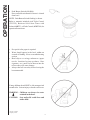
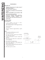
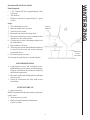
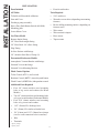
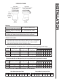
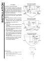
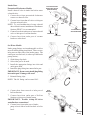
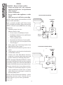
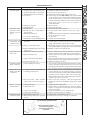
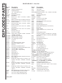
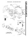
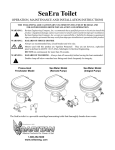
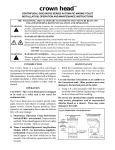
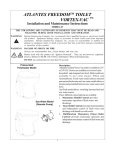
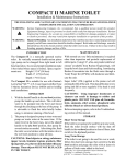
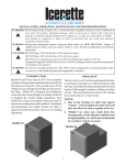
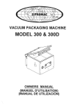
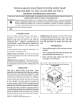
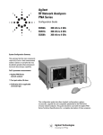
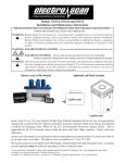
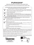
crown head II™
ELECTRIC MARINE TOILET
OPERATION, MAINTENANCE, and INSTALLATION INSTRUCTIONS
Manufactured after June 2002
THE FOLLOWING ARE CAUTIONARY STATEMENTS THAT MUST BE READ AND
FOLLOWED DURING BOTH INSTALLATION AND OPERATION.
WARNING: Raritan Engineering Company, Inc. recommends that a qualified person or electrician install this
product. Equipment damage, injury to personnel or death could result from improper installation. Raritan Engineering Company, Inc. accepts no responsibility or liability for damage to
equipment, or injury or death to personnel that may result from improper installation or
operation of this product.
WARNING: RISK OF SHOCK OR FIRE - Always use recommended fuse/circuit breaker and wire size.
Motors in this product are “Ignition Protected”. They are not however, explosion-proof as
defined in 46CFR 110.15-65(e), Subchapter J-Electrical Engineering.
WARNING: RISK OF FLOODING-Always shut off seacock(s) before leaving the boat unattended.
Whenever possible hose connections should be secured using two stainless steel hose clamps.
Integrity of clamps, hoses and fittings should be checked periodically.
Crown Head II Sea Water Model
Crown Head II Pressurized Freshwater Model
The Crown Head II is an automatic electric
macerating toilet available in Freshwater or
Sea Water flushing.
Four different Flush Control options are
available:
1. Push Button activation - Standard
2. Timed Flush with Push Button - RTC
3. Timed Flush with wall mounted touch
pad - TC*+,*specify voltage and +color
4. Momentary Flush with ability to control intake and discharge seperately SWF100
1-800-352-5630
www.raritaneng. com
OPERATION
•
Push Button Switch (#164000)
Press and hold switch until all waste is cleared
from bowl.
NOTE: Push Button Switch flushing is shown.
Refer to manuals included with Toilet Control
(TC12W), Raritime Solid State Timer with
Solenoid (#RTC), or Flush Control (#SWF100) for
operation Instructions.
•
•
•
•
No special toilet paper is required.
Water should appear in the bowl within ten
seconds of flushing. If not, see troubleshooting
section.
Hard objects or stringy substances (paper
towels, feminine hygiene products, filter
cigarettes, etc.) must not be thrown into the
toilet as they will cause damage.
Always shut off seacock(s) before leaving the
boat unattended.
Young children should NOT be left unsupervised
around toilet. Serious injury or death could occur.
WARNING: Children can drown in water
retained in the bowl.
CAUTION: Seat and/or lid could close and
strike child.
* Specify Voltage
+ Specify Color
2
IMPORTANT: Do not use cleaners that contain
ammonia, ethyl acetate, phosphoric acid or
concentrated chlorine bleach. These will cause
damage to the toilet.
Using C.P. (#1PCP22), a bio-enzymatic toilet bowl
cleaner (available from Raritan Engineering), will
keep the bowl clean and fresh smelling.
C.
P.
Recommend Visual Inspection
✔ For leaks at toilet and hose connections
✔
✔
✔
✔
✔
Hose clamps
Condition of hoses
Seacocks
Condition of wires and connections
In-Line Strainer
Cleaning In-Line Strainer
(Sea Water Models only)
1. Shut off intake seacock.
2. Unscrew strainer bowl.
Filter
3. Remove filter.
4. Clean bowl and filter with a clean dry cloth.
5. Clean gasket and gasket contact surfaces
thoroughly.
Clean Gasket
and Gasket
Contact Surfaces
Thoroughly
Bowl
6. Replace gasket, filter and bowl.
Unscrew
7. Open seacock.
8. Check for leaks.
3
Tighten
MAINTENANCE
MAINTENANCE
Cleaning Instructions
WINTERIZING
WINTERIZING
IMPORTANT
• Improper winter lay up is a major cause of
marine toilet failure.
• Use only nontoxic antifreeze.
• Flush toilet several times to clear waste from
system.
• Dispose of all antifreeze in accordance with
local and federal regulations.
• Winterize holding tanks, plumbing,
treatment systems (MSD’s), etc.
independently following manufacturer’s
instructions.
Sea Water Model
Parts Required
• 1 1/2" (38mm) I.D. piece of hose,
approximately 3 feet (1m) long
• 3/4" (19mm) I.D. piece of hose, approximately
3 feet (1m) long
• Two buckets
• Nontoxic antifreeze approximately 1 quart
(1 liter)
Steps
1. Close intake and discharge seacocks.
2. Turn off power to unit.
3. Disconnect and drain intake hose, discharge
hose and in-line strainer.
4. Connect short hoses to toilet’s intake and
discharge.
5. Place one bucket under hose connected to
toilet’s discharge.
6. Pour antifreeze in other bucket.
7. Place hose connected to intake pump into
bucket with antifreeze.
8. Turn on power to unit and flush until antifreeze
is removed from toilet.
9. Disconnect power to toilet.
Nontoxic
antifreeze
4
WINTERIZING
Pressurized Fresh Water Model
Parts Required
• 1 1/2" (38mm) I.D. hose, approximately 3 feet
(1m) long
• Two buckets
• Nontoxic antifreeze approximately 1 quart
(1 liter)
Steps
1.
2.
3.
4.
5.
Close discharge seacock
Shut off intake water at source.
Turn off power to unit.
Disconnect and drain discharge hose.
Disconnect intake hoses from vacuum breaker
and place in one of the buckets.
6. Connect hose to toilet’s discharge and place in
the other bucket.
7. Pour antifreeze in bowl.
8. Turn on power to unit and flush until antifreeze
is removed from toilet and water is drained
from intake lines.
9. Disconnect power to toilet.
10. Reconnect intake hoses to vacuum breaker.
Nontoxic
antifreeze
Allow water
to drain
into bucket
RECOMMISSIONING
1. Using buckets, hoses, and clean fresh water,
flush antifreeze out of system (see Winterizing).
Dispose of antifreeze in accordance with local
and federal regulations.
2. Reconnect intake and discharge hoses and open
both seacocks.
3. Check all connections for leaks with several
test flushes.
SYSTEM START-UP
1. Open seacock(s).
NOTE: Pressurized freshwater models; open water
source valve.
2. Turn on power to toilet.
3. Flush toilet per Operation Instructions.
Check for leaks.
5
INSTALLATION
INSTALLATION
Parts Included
•
All Toilets
Tools Required
Toilet Bowl (Household or Marine)
•
5/16" nut driver
Seat and Cover
•
Wrench or screw driver (depending on mounting
fastener)
•
Bit for drilling mounting surface (depending on
fastener used)
•
Wire cutters
Discharge pump assembly
Heavy Duty Push Button Switch (#164000)
Mounting pads
Lower Motor Cover
Fuse/circuit breaker
•
Wire terminal crimpers
Sea Water Model
•
Hose cutters
Remote Intake Pump
•
Tape measure
3/4" Hose Barb straight fitting
3/4" Hose Barb - 90° elbow fitting
Plug Fitting
In-Line Strainer with fittings
3/4" Stainless Steel Hose Clamps (2)
Pressurized Freshwater Models
Atmospheric Vacuum Breaker with fittings
Solenoid Valve with fittings
Solenoid Valve Mounting Bracket
Flush Control Options
Toilet Control (#TC*+) wall switch
Raritime Control (#RTC*) times the push button
Flush Control (#SWF100+) independant control
Additional Parts Required
•
Four 1/4" (6mm) stainless steel mounting
bolts or lag screws and washers (Sea Water
Models)
•
Two 1/4" (6mm) stainless steel mounting bolts
or lag screws and washers (Freshwater Models)
•
Four 5/16" (8mm) stainless steel mounting
bolts or lag screws and washers
•
1 1/2" (38mm) I.D. discharge hose
•
3/4" (19mm) I.D. reinforced intake hose
•
3/4" (19mm) and 1 1/2" (38mm) hose clamps
(two for each connection below waterline)
•
Wire
•
Terminals
* Specify Voltage
+ Specify Color
6
Bowl Width:
14 3/8" (36.6cm) Household
13" (33cm) Marine
INSTALLATION
SPECIFICATIONS
Bowl Depth:
19 1/4" (48.9cm) Household
16 3/4" (42.6cm) Marine
Height:
17 3/8"
(44.1cm)
Household
17" (43.2cm)
Marine
Base Depth:
10 7/8"
(27.6cm)
Base Width:
10 1/2"
(26.8cm)
Plumbing
Maximum suction of Intake pump
4 Ft. (1.2m) from Intake Pump
(Maximum height above waterline)
Maximum height of discharge
vented loop
6 Ft. (1.8m) from base of toilet
Pressurized water source must provide a minimum flow rate of 3 gallons
(11.3 liters) per minute at a minimum pressure of 5 psi (34.5 kPa).
NOTES: for Wire Sizes
1. Distances are from source (battery) to unit and back to source (battery).
2. Recommended conductor wire minimum AWG (mm2) for 3% voltage drop.
3. Recommended conductor sizes are based on 105°C rated insulation.
Refer to ABYC Standards for other insulation ratings.
Recommended Wire and Breaker Sizes for Crown Head II with Diaphragm Intake Pump
Main Circuit
Discharge Pump
Units
Voltage Breaker/Fuse Amps Assembly Amps
Diaphragm Intake Distance (feet) and Wire (AWG)
10' 15' 20' 25' 30' 40' 50'
Pump Amps
12V DC
40
18
10
10
8
6
6
4
4
2
24V DC
20
9
5
16
14
12 12 10 10
8
32V DC
15
7
4
16
16
16 16 16 16 14
Recommended Wire and Breaker Sizes for Crown Head II with Pressurized Freshwater
Water Solenoid Distance (feet) and Wire (AWG)
Discharge Pump
Main Circuit
Units
Valve Amps
10' 15' 20' 25' 30' 40' 50'
Voltage Breaker/Fuse Amps Assembly Amps
12V DC
25
18
1
10
10
8
24V DC
15
9
.5
16
16
14 12 12 10 10
32V DC
10
7
.5
16
16
16 14 14 12 12
8
6
6
4
Branch Circuit Wire to Water Solenoid Valve: use 16 AWG Wire
Wire Sizes Conversion Table
AWG 16
14
12
10
mm
2.5
4.0
6.0
2
1.5
8
6
10.0 16.0
Feet to Meter Conversion Table
4
2
Feet
25.0 35.0
7
10
15
20
25
30
40
50
Meter 3.1
4.6
6.1
7.2
9.2
12.2
15.2
INSTALLATION
Mounting Toilet
Mounting surface must be flat and solid.
IMPORTANT: Do not mount where it may be
subject to shower spray or other sources of
external water.
1. Install seat on toilet.
2. Place toilet where it will be located.
Make sure there is room to route hoses.
Make sure seat will open properly.
3. Mark location of toilet base mounting holes on
mounting surface.
4. Drill holes for toilet mounting bolts/screws.
NOTE: Hole size will depend on type of bolt/screws
used (5/16" [8mm] size bolts/screws are
recommended).
5.
6.
7.
8.
Mark locations for hoses where required.
Cut holes for hoses.
Place rubber mounting strips under base plate.
Secure toilet to surface.
Mounting Water Solenoid Valve
(Pressurized Freshwater Models Only)
1. Locate valve on a solid flat surface in an area
that is dry and well ventilated.
2. Mark and drill holes for water solenoid mounting
bracket.
NOTE: Hole size will depend on type of bolts/screws
used (1/4" [6mm] size bolt/screws are
recommended).
3. Mount bracket.
4. Install fittings provided (PLA14) on valve’s inlet
and outlet ports.
5. Attach valve to bracket. Valve must be mounted
according to flow markings on valve body.
From
Pressurized
Freshwater
Source
IN
OUT
8
PLA14
To Crown Head II
➔
6"
(15.3cm)
(Pressurized Freshwater Model only)
➔
1. Install fittings as shown.
2. Locate mounting area that is a minimum of
6" (15.3cm) above toilet.
3. Secure where top is in horizontal position.
Mounting In-Line Strainer
(Seawater Models Only)
Make sure strainer bowl is tight.
1. Locate strainer where it will be accessible.
2. Mark and drill mounting holes.
Flow Marking
NOTE: Hole size will depend on type of bolts/
screws used (1/4" [6mm] size bolts/screws are
recommended).
3. Install fittings provided (#PLA14) on strainer’s
inlet and outlet ports.
4. Mount strainer. Strainer must be mounted
according to flow markings on strainer body.
Mounting Remote Intake Pump
(Sea Models Only)
1. Locate on a flat solid surface in an area that is
dry and well ventilated.
NOTE: Location should not be greater than 48"
(122cm) above the waterline.
2. Mark and drill mounting holes.
NOTE: Hole size will depend on type of bolts/
screws used (1/4" [6mm] size bolts/screws are
recommended).
3. Mount pump. Do not over tighten bolts.
Installing Lower Cover
1. Slide cover over lower unit.
2. Secure in place with plastic beaded tie.
NOTE: Do not install until installation is
completed.
9
INSTALLATION
Mounting Atmospheric Vacuum Breaker
INSTALLATION
Remote Intake Pump Model
Mounted Above Waterline
PLUMBING
WARNING: Hazard of Flooding
Toilets mounted at or below the waterline must
have a vented loop installed in the discharge
line. The top of the vented loop must be a
minimum of 4" (10cm) above the waterline at
the boats greatest angle of heel (see vented loop
manufacturer’s instructions).
Waterline
Waterline
In-Line
Strainer
Intake
Seacock
Double clamp all below waterline connections.
•
•
•
•
•
Fittings and 90° bends should be kept to a
minimum.
In-Line Strainer must be installed before
the Remote Intake pump. Failure to do so
may void warranty.
Discharging untreated sewage is restricted
in all U. S. waters within the three-mile
limit. If boating outside of U.S. Boundaries
check with local authorities for their rules
and regulations.
Thru-hull fittings and seacocks must be
installed where they are easily accessible.
Use only quality reinforced hoses.
Secure all hoses properly.
Y Valve
Lectra/San
Discharge
Seacock
Remote Intake Pump Model
Mounted Below Waterline
•
•
Discharge
Vented
Loop
Holding Tank
Sea Water Models must also have a vented loop
installed between the intake pump and the
toilet bowl.
Hazard of potable water contamination.
Vacuum breaker must be installed with
installations using potable water.
IMPORTANT:
Remote
Intake
Pump
Crown head II
Intake
Vented
Loop
Waterline
Crown head II
Discharge
Vented
Loop
Waterline
Lectra/San
Intake
Seacock
Discharge
Seacock
In-Line
Strainer
Remote Intake
Pump
Pressurized Freshwater Model
Installed Above Waterline
Water
Solenoid
Valve
Vacuum
Breaker
Crown head II
Waterline
Waterline
Holding Tank
Discharge Lines
1. Connect quality 1 1/2" (38mm) sanitation
hose to discharge fitting on toilet.
2. Run hose to appropriate device (i.e.: treatment
system, holding tank, etc.).
10
Shut off
Valve
From Pressurized
Freshwater Source
(Shut Off Valve)
IN
OUT
To Inlet Port of
Vacuum Breaker
Outlet Port
Inlet Port
Outlet Port
INSTALLATION
Intake Lines
Pressurized Freshwater Models
Install a shut off valve in intake line before water
solenoid valve.
1. Connect hose from pressurized freshwater
source to a shut off valve.
2. Connect hose from shut off valve to inlet port
of water solenoid valve.
NOTE: To avoid malfunction of water solenoid
due to debris in water, installation of Freshwater
Strainer (FWSC*) is recommended.
3. Connect hose from outlet port of water solenoid
valve to inlet port of vacuum breaker.
4. Connect hose from outlet port of vacuum
breaker to toilet bowl.
Arrow
Sea Water Models
Intake pump fittings are interchangeable to allow
more flexibility during installation. There are two
inlet ports on either side of the intake pump. The
outlet port (to toilet bowl) is at the top of the intake
pump (Arrow).
1. Slide fitting clips back.
2. Select inlet port to be used.
3. Install the appropriate fittings into inlet and
outlet ports used.
4. Install the plug fitting into unused inlet port.
Inlet Ports
IMPORTANT: Be sure not to install plug fitting
into outlet port! Damage will occur!
5. Reinstall fitting clips.
NOTE: The 90° fitting can be rotated 360°.
From
Seacock
6. Connect hose from seacock to inlet port of
In-Line Strainer.
7. Connect hose from outlet port of In-Line
Strainer to inlet port of intake pump.
IMPORTANT: Double clamp all below
waterline hose connections!
8. Connect hose from outlet port of intake
pump to bowl elbow located on back of toilet
bowl.
11
To Intake
Pump
WIRING
WIRING
WARNING: Hazard of Shock and Fire
• Always use proper wire, wire connectors
and fuse/circuit breaker. See Specification
Chart on page 7.
• Secure wire properly.
• Do not connect other appliances to toilet
circuit.
• Make sure power is off before proceeding.
Remote Intake Pump Wiring
NOTE: Figures shown with installation of Push
Button Switch (#164000).
Push Button
Switch
(#164000)
Refer to manuals included with Toilet Control
(TC*+), Raritime Solid State Timer with Solenoid
(#RTC), or Flush Control (#SWF100+) for wiring
Instructions.
NEG (-)
POS (+)
Fuse or
Circuit
Breaker
1. Determine proper size wire.
Measure distance from:
• Power source to Push Button Switch.
• Push Button Switch to toilet (and Remote
Intake Pump if used).
• Toilet to ground source.
• Determine total distance of wire needed.
• Select proper size wire from Specification
Chart on page 7.
2. Select proper size fuse/circuit breaker from
Specifications Chart on page 7.
3. Install fuse/circuit breaker in positive line at
source.
4. Connect positive wire from fuse/circuit breaker
to Push Button Switch.
5. Connect wire from Push Button Switch to
orange wire on remote intake pump motor and
positive terminal on discharge pump motor.
POS (+)
Orange
NEG
POS
Pressurized Freshwater Wiring
Push Button
Switch
#164000)
POS (+)
3 Amp
Fuse
NOTE: Pressurized Freshwater Models; connect
wire from Push Button Switch to positive terminal
on discharge pump motor and from Push Button
Switch to one of the wires on water solenoid valve.
The water solenoid valve is not polarity sensitive.
Solenoid
Valve
6. Connect wire from battery negative or power
source ground buss to black wire on remote
intake pump motor and negative terminal on
discharge pump motor.
Fuse or
Circuit
Breaker
NEG (-)
NEG
NOTE: Pressurized Freshwater Models; connect
remaining wire from water solenoid valve to
battery negative or power source ground buss.
* Specify Voltage
+ Specify Color
NEG (-)
Black
12
POS
A.
B.
Poor Discharge, A1. Clogged or restricted discharge line.
Especially Solids: A2. Too many bends or ells in discharge line.
A3. Clogged holding tank or vented loops.
A4. Mineral buildup in hoses and fittings.
A5. Low voltage.
A6.
A7.
Poor Water Flow, B1.
Especially at Front B2.
of Bowl (or no water
B3.
flow):
Damage to pump wall.
Full holding tank.
Head not level.
Restriction in line to Intake Pump or
clogged strainer.
Intake Pump sucking air.
B4. Low voltage to Intake Pump.
B5. Intake pumps valves and diaphragm worn.
For Pressurized Freshwa- B1A.Inadequate water supply to water solenoid valve.
ter toilets only. Poor
intake water flow.
B2A.Clogged water solenoid valve.
C.
D.
E.
F.
G.
Conclusion
A1.
A2.
A3.
A4.
A5.
Be sure discharge seacock is open. Clean lines. Remove clog.
Replumb to eliminate bends and ells.
Clean vents and any vent valves.
Manually clean affected parts and/or replace hoses.
Check voltage at toilet while running. If less than nominal
voltage of toilet (12, 24, 32, 120V), check condition of batteries.
Check terminals and wire connections for corrosion (heat at
terminals and junctions indicates a bad or corroded connection).
Check gauge of wire to be sure it is not undersize, see
Specification Table.
A6. Replace CH120.
A7. Find a pump out station.
B1. Raise rear of toilet; check with level.
B2. Be sure seacock is open. Clear line - remove clog. Clean
strainer.
B3. Check all connections from intake thru-hull to Intake Pump to
be sure no air leaks are present.
B4. See A5, above.
B5. Replace valves and diaphragm.
B1A.Check available water flow; requires minimum of three GPM
at bowl elbow. 1) Increase line pressure. 2) Install larger
piping. 3) Install higher capacity pressure pump.
B2A.Disassemble and clean waterb solenoid valve. Install Fresh
water strainer (#FWSC) in supply line to water solenoid valve.
B3A.Rebuild or replace water solenoid valve.
B3A.Faulty or malfunctioning water solenoid
valve or coil.
C1. Remove and flush bowl with pressure hose to remove all
Foul Odors From C1. “Marine life” lodged in rim of bowl.
material. Install strainer in intake line to avoid recurrence.
Toilet Area:
C2. Improper discharge hose.
C2. Replace plastic hose with quality sanitation hose (#SH) with
smooth interior .
C3. Sewage remaining in discharge line.
C3. Flush toilet long enough to insure waste has passed out of hose.
Replace plastic hose with quality sanitation hose (#SH).
C4. Clogged holding tank vent.
C4. Clean vents and any vent valves.
D. Close seacocks one at a time to determine which one is causing
Bowl Fills Up While D. Pressure buildup at seacock(s).
problem. If intake, install vented loop between pressure side
Boat is Underway:
of pump and bowl. If discharge, install vented loop in discharge
line. If problem continues, contact Raritan Technical Support.
Bowl Fills Up E1. Freshwater models: Water solenoid valve E1. Remove supply hose between toilet and water solenoid valve
not shutting completely off.
at water solenoid valve. If continuous dripping or seeping is
Whether or Not Boat
noted, water solenoid valve should be disassembled and cleaned.
is Underway:
If problem persists, rebuild or replace water solenoid valve.
Water solenoid valve requires a minimum of 5 psi at all times
at intake of the valve to stay closed.
E2. Raw water models: Below waterline E2. Remove vent from vented loop. Clean out foreign matter.
toilet, vent of vented loop is clogged.
Install an In-Line strainer (#163000) in supply line to Intake
Pump.
F1. Tighten (4) bowl mounting nuts.
Water
Leaking F1. Leaking bowl gasket.
F2. Leaking front cover.
F2. Remove front cover (#CH18) and inspect “O” ring for damage.
From Macerator:
Replace “O” ring if necessary using Super Lube or waterproof
grease to reassemble.
F3. Leaks at hoses or fittings.
F3. Check all connections; be sure clamps are tight.
F4. Leaking macerator shaft seal.
F4. Return to factory for repairs or exchange.
G1. Remove front cover and remove object.
Loud Noises Ema- G1. Object jammed in macerator.
nating From Toilet: G2. Motor bearings damaged by macerator G2. Return motor to factory for servicing or replacement.
seal leak.
Tip for Removing Intake Pump
Plug
Set screw must be loosened
with 1/8" hex key before
removing the intake pump
from motor
12
13
TROUBLESHOOTING
TROUBLESHOOTING
Possible Cause
Problem
EXPLODED PARTS
CROWN HEAD II - Parts List
Part #
Description
Part #
1118
1222AW
1222B
1226B
1234
1236AW
1236E
1237W
Lockwasher (4)
90 Degree discharge (opt.)
Straight discharge
1/4" - 20 S/S Hex Nut (4)
Bowl Gasket
Bowl Spud Assembly
Bowl Elbow
Marine-size Bowl Assembly (White)
(Not shown)
Marine-size Seat and Cover (White) (Not shown)
Household-style Bowl Assembly, (Bone)
includes 1236AW
Household-style Bowl Assembly, (White)
includes 1236AW
Household-style Seat and Cover (White)
(Not shown)
Household-style Seat and Cover (Bone)
(Not shown)
Discharge Screw (2)
Front Cover O-Ring
Intake Pump Assembly includes 162100W,
162200W, 162300W
Upper Housing Assembly
Middle Housing Assembly
Lower Housing Assembly
Cone Seal
O-Ring
Lower Housing includes 162315
Diaphragm includes 162315
Piston (4)
Piston Seat (4) includes 162315
Bearing Plate Assembly includes F005, 162315
3/4" Hose Barb - 90° Fitting
3/4" Hose Barb - Straight Fitting
Plug Fitting
Fitting Clip (3)
Fitting O-Ring (3)
In-line Strainer
Heavy Duty Push Button Switch (Not shown)
Remote Motor
Diaphragm Intake Pump Assembly 12V
includes 162100W, 162200W, 162300W,
1660*A
Diaphragm Intake Pump Assembly 24V
includes 162100W, 162200W, 162300W,
1660*A
Diaphragm Intake Pump Assembly 32V
includes 162100W, 162200W, 162300W,
1660*A
Motor Shaft Seal w/316 Spring (Not shown)
Crown Head II Motor, 12, 24, 32 VDC
Lower Cover, Bone, Household-style
Lower Cover, White, Household-style
C250
Beaded Wire Tie
C253
Joker Valve
C290
Discharge Adapter
CH119MWDischarge Impeller Assy. includes CH119M,
F149VT [2])
CH120
Discharge Pump Wall
CH121
Macerator
CH15DD End Bell
CH18W
Front Cover w/"O" Ring
CH26
Front Cover Screw (6
CH27
Mounting Screw (4)10-32x5/8" S/S
CH34
Woodruff Key
CH38
Bowl Stud (4)
CH51
Base Mounting Screw (4)
CH52
Rubber Mounting Strip (2), (Not shown)
CH55
Base Plate
CH57
Rubber Slinger
CH58
Fillister Head Screw (4) 10-32x3/4" S/S
CH59
Seal
CH92
Square Rubber Gasket
CR1
Discharge Impeller and Macerator Assembly
includes CH120, CH121, F149VT(2), CH119MW
F005
Set Screw
F020
Piston Fastener (4)
F144
Mounting Bolt Washer (4)
F149VT
Set Screw (2)
F161
Cap Fastener (4)
F162VT
Mounting Bolt
LWPLUG 3/8" Plastic Plug
M23A
#10 Lockwasher (4)
M30
1/4" - 20 Brass Nut (4)
M31
#14 Brass Washer (4)
RNI
Nylon Shoulder Washer (4)
WATER SOLENOID VALVE
CWPS*A 1/2" GC Solenoid Valve
CWPSMB Mounting Bracket for CWPS (Not shown)
PLA7
Male Adapter 1/2 MNPTx3/4 Barb (2)
ATMOSPHERIC VACUUM BREAKER
PLAVB0-5 Atmospheric Vacuum Breaker
PLA13
Elbow, 1/2” NPT x 3/4”
PLA14
Male Adapter 1/2 MNPTx3/4 Barb
ADDITIONAL ACCESSORIES AVAILABLE
TC*+
Toilet Control (Not shown)
FWSC
Fresh Water Strainer (Not shown)
RTC*
Raritime Solid State Timer with solenoid
(Not shown)
SH
Sanitation Hose (Not shown)
SWF100+ Flush Control (Not shown)
TWK
Toilet Water Kit (Not shown)
VL1½W
Vented Loop 1½" (Not shown)
1238A
1244AW
1244W
1245
1245A
1341
161107
162000W
162100W
162200W
162300W
162135
162225
162305
162310
162315
162320
162325A
162405
162410
162415
162420
162425
163000
164000
1660*A
166000
166100
166200
31-102
C2M*
C246
C247
* Specify Voltage
+ Specify Color
14
Description
1237W,
1244AW,
1244W
C250
1236AW
1226B
RNI
CH26
CH18W
161107 CH120
F149VT
CH121
CH119MW
1236E
CH38
Water Solenoid Valve
1234
PLA14
CH15DD
CR1
C246, 247
CH59
CH57
F149VT
M23
CH58
CH27
CWPS*A
CH34
M30
M31
CH92
PLA14
C290
In-Line Strainer
C2M*
1341
C253
163000
CH55
1222B
1222AW
1118
CH51
Atmospheric Vacuum Breaker
PLAVB0-5
PLA13
1660*A
162300W
PLA13
F005
PLA14
162325A
F020
162200W
162410
162305
162320
162225
162310
162425
162420
162315
162415
162100W
162425
162135
INTAKE PUMP
Exploded parts view
F144
162420
M23A
162405
15
162425
F162VT
EXPLODED PARTS
CROWN HEAD II - EXPLODED PARTS VIEW
LIMITED WARRANTY
Raritan Engineering Company warrants to the original purchaser that this product is free of defects in
materials or workmanship for a period of one year from the product’s date of purchase. Should this
product prove defective by reason of improper workmanship and/or materials within the warranty
period, Raritan shall, at its sole option, repair or replace the product.
1. TO OBTAIN WARRANTY SERVICE, Consumer must deliver the product prepaid, together with a
detailed description of the problem, to Raritan at 530 Orange St., Millville, N.J. 08332, or 3101 SW 2nd
Ave. Ft. Lauderdale, FL 33315. When requesting warranty service, purchaser must present a sales slip
or other document which establishes proof of purchase. THE RETURN OF THE OWNER
REGISTRATION CARD IS NOT A CONDITION PRECEDENT OF WARRANTY COVERAGE.
However, please complete and return the owner Registration Card so that Raritan can contact you should
a question of safety arise which could affect you.
2. THIS WARRANTY DOES NOT COVER defects caused by modifications, alterations, repairs or
service of this product by anyone other than Raritan; defects in materials or workmanship supplied by
others in the process of installation of this product; defects caused by installation of this product other
than in accordance with the manufacturer’s recommended installation instructions or standard industry
procedures; physical abuse to, or misuse of, this product. This warranty also does not cover damages
to equipment caused by fire, flood, external water, excessive corrosion or Act of God.
3. ANY EXPRESS WARRANTY NOT PROVIDED HEREIN, AND ANY REMEDY FOR BREACH
OF CONTRACT WHICH BUT FOR THIS PROVISION MIGHT ARISE BY IMPLICATION OR
OPERATION OF LAW, IS HEREBY EXCLUDED AND DISCLAIMED. ALL IMPLIED
WARRANTIES SUCH AS THOSE OF MERCHANTABILITY AND OF FITNESS FOR A
PARTICULAR PURPOSE, IF APPLICABLE, AS WELL AS ANY IMPLIED WARRANTIES
WHICH MIGHT ARISE BY IMPLICATION OF LAW, ARE EXPRESSLY LIMITED TO A TERM
OF ONE YEAR. SOME STATES DO NOT ALLOW LIMITATIONS ON HOW LONG A LIMITED
WARRANTY LASTS, SO THE ABOVE LIMITATION MAY NOT APPLY TO YOU.
4. UNDER NO CIRCUMSTANCES SHALL RARITAN BE LIABLE TO PURCHASER OR ANY
OTHER PERSONS FOR ANY SPECIAL OR CONSEQUENTIAL DAMAGES, WHETHER ARISING
OUT OF BREACH OF WARRANTY, BREACH OF CONTRACT, OR OTHERWISE. SOME
STATES DO NOT ALLOW THE EXCLUSION OR LIMITATION OF INCIDENTAL OR
CONSEQUENTIAL DAMAGES, SO THE ABOVE LIMITATION OR EXCLUSION MAY NOT
APPLY TO YOU.
5. No other person or entity is authorized to make any express warranty, promise or affirmation of fact or
to assume any other liability on behalf of Raritan in connection with its products except as specifically
set forth in this warranty.
6. This warranty gives you specific legal rights, and you may also have other rights which vary from state
to state.
530 Orange Street, Millville, NJ 08332 USA
Telephone: 856-825-4900 FAX: 856-825-4409
www.raritaneng.com
Southern Office and Plant:
3101 SW Second Avenue, Fort Lauderdale, FL 33315 USA
Telephone: 954-525-0378 FAX: 954-764-4370
L339 0407kgs
Specifications Subject to Change Without Notice
16
Printed in U.S.A.