1
Dominion KX II-101-V2
User Guide
Release 3.5.0
Copyright © 2012 Raritan, Inc.
KX2101V2-v3.5.0-D-E
September 2012
255-62-3059-00
This document contains proprietary information that is protected by copyright. All rights reserved. No
part of this document may be photocopied, reproduced, or translated into another language without
express prior written consent of Raritan, Inc.
© Copyright 2012 Raritan, Inc. All third-party software and hardware mentioned in this document are
registered trademarks or trademarks of and are the property of their respective holders.
FCC Information
This equipment has been tested and found to comply with the limits for a Class A digital device,
pursuant to Part 15 of the FCC Rules. These limits are designed to provide reasonable protection
against harmful interference in a commercial installation. This equipment generates, uses, and can
radiate radio frequency energy and if not installed and used in accordance with the instructions, may
cause harmful interference to radio communications. Operation of this equipment in a residential
environment may cause harmful interference.
VCCI Information (Japan)
Raritan is not responsible for damage to this product resulting from accident, disaster, misuse, abuse,
non-Raritan modification of the product, or other events outside of Raritan's reasonable control or not
arising under normal operating conditions.
If a power cable is included with this product, it must be used exclusively for this product.
In Raritan products which require Rack Mounting, please follow these precautions:
Operation temperature in a closed rack environment may be greater than room temperature. Do
not exceed the rated maximum ambient temperature of the appliances. See Specifications (on
page 184).
Ensure sufficient airflow through the rack environment.
Mount equipment in the rack carefully to avoid uneven mechanical loading.
Connect equipment to the supply circuit carefully to avoid overloading circuits.
Ground all equipment properly, especially supply connections, such as power strips (other than
direct connections), to the branch circuit.
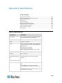
Contents
Chapter 1 Introduction
1
KX II-101-V2 Overview .................................................................................................................. 2
KX II-101-V2 Help .......................................................................................................................... 3
What's New in the Help ....................................................................................................... 4
Related Documentation ....................................................................................................... 4
Product Photos .............................................................................................................................. 5
Product Features ........................................................................................................................... 5
Interfaces ............................................................................................................................. 5
Network Configuration ......................................................................................................... 5
System Management Features ........................................................................................... 6
Administration Features ....................................................................................................... 6
User Features ...................................................................................................................... 7
Power ................................................................................................................................... 7
Video Resolution.................................................................................................................. 7
Mounting .............................................................................................................................. 7
Terminology ................................................................................................................................... 7
Package Contents .......................................................................................................................... 8
Chapter 2 Installation and Configuration
9
Overview ........................................................................................................................................ 9
Default Login Information ............................................................................................................... 9
Getting Started ............................................................................................................................. 10
Step 1: Configure the Target Server.................................................................................. 10
Step 2: Configure Network Firewall Settings ..................................................................... 21
Step 3: Connect the Equipment......................................................................................... 22
Step 4: Configure the KX II-101-V2 ................................................................................... 27
Chapter 3 Working with Target Servers
35
Interfaces ..................................................................................................................................... 35
KX II-101-V2 Remote Console Interface ........................................................................... 35
Multi-Platform Client (MPC) ............................................................................................... 43
Virtual KVM Client (VKC) ............................................................................................................. 44
Overview ............................................................................................................................ 44
Connecting to a KVM Target Server.................................................................................. 44
Toolbar Buttons and Status Bar Icons ............................................................................... 44
Power Controlling a Target Server .................................................................................... 46
Disconnecting KVM Target Servers .................................................................................. 46
Connection Properties ....................................................................................................... 47
Connection Information ..................................................................................................... 49
Keyboard Options .............................................................................................................. 49
iii
Contents
Video Properties ................................................................................................................ 55
Mouse Options................................................................................................................... 60
VKC Virtual Media ............................................................................................................. 64
Tool Options ...................................................................................................................... 64
View Options ...................................................................................................................... 68
Help Options ...................................................................................................................... 69
Chapter 4 Virtual Media
71
Overview ...................................................................................................................................... 72
Prerequisites for Using Virtual Media ................................................................................ 74
Virtual Media in a Windows XP Environment .................................................................... 75
Virtual Media in a Linux Environment ................................................................................ 76
Virtual Media in a Mac Environment .................................................................................. 78
Conditions when Read/Write is Not Available ................................................................... 78
Using Virtual Media ...................................................................................................................... 78
Connecting to Virtual Media ......................................................................................................... 80
Local Drives ....................................................................................................................... 80
Mounting CD-ROM/DVD-ROM/ISO Images ...................................................................... 81
Disconnecting Virtual Media ........................................................................................................ 82
Chapter 5 User Management
83
User Groups ................................................................................................................................. 83
User Group List.................................................................................................................. 84
Relationship Between Users and Groups ......................................................................... 84
Adding a New User Group ................................................................................................. 84
Modifying an Existing User Group ..................................................................................... 88
Users ............................................................................................................................................ 89
View KX II-101-V2 User List .............................................................................................. 89
View Users by Port ............................................................................................................ 90
Disconnecting Users from Ports ........................................................................................ 90
Logging Users Off the KX II-101-V2 (Force Logoff) .......................................................... 91
Adding a New User ............................................................................................................ 91
Modifying an Existing User ................................................................................................ 92
Blocking and Unblocking Users ......................................................................................... 92
Authentication Settings ................................................................................................................ 93
Implementing LDAP/LDAPS Remote Authentication ........................................................ 94
Returning User Group Information from Active Directory Server ...................................... 98
Implementing RADIUS Remote Authentication ................................................................. 99
Returning User Group Information via RADIUS .............................................................. 101
RADIUS Communication Exchange Specifications ......................................................... 102
User Authentication Process ........................................................................................... 103
Changing a Password ................................................................................................................ 105
Chapter 6 Device Management
106
Network Settings ........................................................................................................................ 106
Network Basic Settings .................................................................................................... 107
LAN Interface Settings ..................................................................................................... 110
iv
Contents
Device Services ......................................................................................................................... 111
Enabling Telnet ................................................................................................................ 111
Enabling SSH .................................................................................................................. 111
HTTP and HTTPS Port Settings ...................................................................................... 112
Entering the Discovery Port ............................................................................................. 112
Enabling Direct Port Access via URL .............................................................................. 112
Configuring SNMP Agents ............................................................................................... 113
Keyboard/Mouse Setup ............................................................................................................. 115
Serial Port Settings .................................................................................................................... 115
Admin Port ....................................................................................................................... 116
Raritan Power Strip Control ............................................................................................. 116
Modem ............................................................................................................................. 116
Configuring Date/Time Settings ................................................................................................. 117
Event Management .................................................................................................................... 118
Configuring Event Management - Settings ...................................................................... 118
Configuring Event Management - Destinations ............................................................... 125
Port Configuration ...................................................................................................................... 126
Managing KVM Target Servers (Port Page) .................................................................... 127
Power Control .................................................................................................................. 128
Analog KVM Switch ................................................................................................................... 133
Resetting the KX II-101-V2 Using the Reset Button .................................................................. 134
Changing the Default GUI Language Setting ............................................................................ 135
Chapter 7 Managing USB Connections
136
Overview .................................................................................................................................... 137
USB Connection Settings .......................................................................................................... 137
Advanced USB Connection Settings ......................................................................................... 138
Chapter 8 Security Management
140
Security Settings ........................................................................................................................ 140
Login Limitations .............................................................................................................. 140
Strong Passwords............................................................................................................ 142
User Blocking................................................................................................................... 143
Encryption & Share .......................................................................................................... 145
Enabling FIPS 140-2 ....................................................................................................... 148
v
Contents
Configuring IP Access Control ................................................................................................... 149
SSL Certificates ......................................................................................................................... 152
Security Banner ......................................................................................................................... 155
Chapter 9 Maintenance
156
Audit Log .................................................................................................................................... 156
Device Information ..................................................................................................................... 157
Backup and Restore .................................................................................................................. 158
Upgrading Firmware .................................................................................................................. 160
Upgrade History ......................................................................................................................... 161
Factory Reset ............................................................................................................................. 161
Rebooting the KX II-101-V2 ....................................................................................................... 162
Stopping CC-SG Management .................................................................................................. 163
Chapter 10 Diagnostics
165
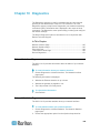
Network Interface Page ............................................................................................................. 165
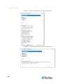
Network Statistics Page ............................................................................................................. 165
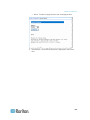
Ping Host Page .......................................................................................................................... 168
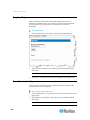
Trace Route to Host Page ......................................................................................................... 168
Device Diagnostics .................................................................................................................... 170
Chapter 11 Command Line Interface (CLI)
172
Overview .................................................................................................................................... 172
Accessing the KX II-101-V2 Using the CLI ................................................................................ 173
SSH Connection to the KX II-101-V2......................................................................................... 173
SSH Access from a Windows PC .................................................................................... 173
SSH Access from a UNIX/Linux Workstation .................................................................. 174
Logging in .................................................................................................................................. 174
Navigation of the CLI ................................................................................................................. 174
CLI Prompts ..................................................................................................................... 174
Completion of Commands ............................................................................................... 175
CLI Syntax -Tips and Shortcuts ....................................................................................... 175
Common Commands for All Command Line Interface Levels ........................................ 175
CLI Commands .......................................................................................................................... 176
Diagnostics ...................................................................................................................... 177
Configuration ................................................................................................................... 178
Listports Command.......................................................................................................... 180
Userlist Command ........................................................................................................... 180
vi
Contents
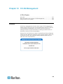
Chapter 12 CC-SG Management
181
Overview .................................................................................................................................... 181
Removing a KX II-101-V2 from CC-SG Management ............................................................... 182
Using CC-SG in Proxy Mode ..................................................................................................... 183
Appendix A Specifications
184
Physical Specifications .............................................................................................................. 184
Supported Operating Systems (Clients) .................................................................................... 185
Supported Browsers .................................................................................................................. 186
Connectors ................................................................................................................................. 186
Certified Modems ....................................................................................................................... 187
Supported Video Resolutions .................................................................................................... 187
Supported Keyboard Languages ............................................................................................... 188
TCP and UDP Ports Used ......................................................................................................... 189
Network Speed Settings ............................................................................................................ 191
9 Pin Pinout ................................................................................................................................ 192
Appendix B Updating the LDAP Schema
193
Returning User Group Information ............................................................................................. 193
From LDAP ...................................................................................................................... 193
From Microsoft Active Directory ...................................................................................... 193
Setting the Registry to Permit Write Operations to the Schema ............................................... 194
Creating a New Attribute ............................................................................................................ 194
Adding Attributes to the Class ................................................................................................... 195
Updating the Schema Cache ..................................................................................................... 197
Editing rciusergroup Attributes for User Members ..................................................................... 197
Appendix C Rack Mount
201
Attach the L Bracket to the KX II-101-V2 for a Horizontal Mount .............................................. 201
Appendix D Informational Notes
203
Java Runtime Environment (JRE) ............................................................................................. 203
IPv6 Support Notes .................................................................................................................... 204
Operating System IPv6 Support Notes ........................................................................... 204
Keyboard, Video and Mouse Notes ........................................................................................... 204
Sun Blade Video, Keyboard, and Mouse Support Limitation .......................................... 205
BIOS Access Limitation from a Local Keyboard .............................................................. 205
HP UX RX 1600 Keyboard and Mouse Configuration ..................................................... 206
Compaq Alpha and IBM P Server Mouse Mode Limitation ............................................. 206
Windows 2000 and Windows 2003 Server Keyboard Limitations ................................... 206
CC-SG ....................................................................................................................................... 206
Proxy Mode and MPC ..................................................................................................... 206
vii
Contents
Appendix E FAQs
207
General FAQs ............................................................................................................................ 207
IPv6 Networking ......................................................................................................................... 208
Index
viii
211
Chapter 1
Introduction
In This Chapter
KX II-101-V2 Overview ..............................................................................2
KX II-101-V2 Help ......................................................................................3
Product Photos ..........................................................................................5
Product Features .......................................................................................5
Terminology ...............................................................................................7
Package Contents .....................................................................................8
1
Chapter 1: Introduction
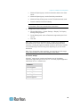
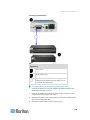
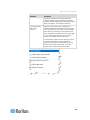
KX II-101-V2 Overview
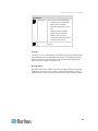
Thank you for purchasing the Dominion KX II-101-V2. The KX II-101-V2
provides a single keyboard, video, and mouse (KVM) port for connection
to a target server, and a single IP port for connection to an IP network.
Within the KX II-101-V2 device, KVM signals from your server are
converted to IP format and compressed for transmission over an IP
network.
The KX II-101-V2 dongle form-factor makes it easy to install near the
target server, and each individual KX II-101-V2 device has its own IP
address. Each device is powered via an external AC-DC power pack.
The KX II-101-V2 can operate as a standalone appliance or integrated
into a single logical solution, along with other Raritan access products,
using Raritan's CommandCenter Secure Gateway (CC-SG) 5.4 or later
management unit.
2
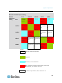
Chapter 1: Introduction
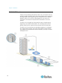
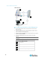
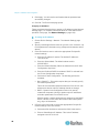
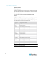
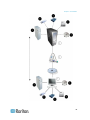
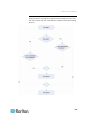
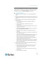
Diagram key
KX II-101-V2
LAN
Windows®, Linux® and Sun™ servers
TCP/IP
LAN
Remote (network) access
Mobile access via iPhone® and iPad® using CC-SG
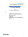
KX II-101-V2 Help
The KX II-101-V2 help provides information on how to install, set up, and
configure the KX II-101-V2. It also includes information on accessing
target servers, using virtual media, managing users and security, and
maintaining and diagnosing the KX II-101-V2.
See the KX II-101-V2 release notes for important information on the
current release before you begin using the KX II-101-V2.
A PDF version of the help can be downloaded from the Raritan
Firmware and Documentation page on the Raritan website. Raritan
recommends that you refer to the Raritan website for the most up-to-date
user guides available.
To use online help, Active Content must be enabled in your browser. If
you are using Internet Explorer 7, you must enable Scriplets. Consult
your browser help for information on enabling these features.
3
Chapter 1: Introduction
What's New in the Help
The following information has been added based on enhancements and
changes to the equipment and/or user documentation.
Support for FIPS 140-2 encryption
Support for a login security banner
Mobile access from iPad® and iPhone® to servers connected to a KX
II-101-V2 being managed by CC-SG
SNMPv3 support
Ability to upload your own SSL certificate to the KX II-101-V2
Support for 1920x1080 & wide screen video resolutions
Configurable TCP/IP port numbers (Stealth Mode)
Direct access to the KX II-101-V2 while under CC-SG 5.4 or later
management
Virtual media support for Linux® and Mac®
Japanese, Traditional Chinese and Simplified Chinese user interface
support
Support for IPv4 and IPv6 in a dual stack environment
Disconnecting users from ports
Forced user log off
Updates to the SNMP trap and SNMP agent user interface in KX II101-V2
Please see the KX II-101-V2 Release Notes for a more detailed
explanation of the changes applied to the appliance and this version of
the help.
Related Documentation
The KX II-101-V2 help is accompanied by the KX II-101-V2 Quick Setup
Guide, which can be found on the Raritan Firmware and
Documentation page of Raritan's website
(http://www.raritan.com/support/firmware-and-documentation).
Installation requirements and instructions for client applications used with
the KX II-101-V2 can be found in the KVM and Serial Access Clients
Guide, also found on the Raritan website. Where applicable, specific
client functions used with the KX II-101-V2 are included in the help.
4
Chapter 1: Introduction
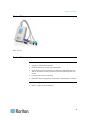
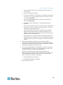
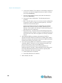
Product Photos
KX II-101-V2
Product Features
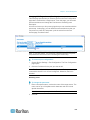
Interfaces
Integrated PS/2 KVM connection
USB connection for control and virtual media
Serial Admin port for initial device configuration and diagnostics, as
well as use with an external modem access and Raritan power strip
control
Local port for monitor connection
Ethernet LAN port supporting 10/100-base-T autosensing, full duplex
Network Configuration
DHCP or static IP device address
5
Chapter 1: Introduction
System Management Features
Firmware upgradable over Ethernet
Failsafe firmware upgrade capability
Clock that can be set manually or via synchronization with Network
Time Protocol (NTP/SNTP)
Local, timestamped, administrator activity log SNMP V2 agent that
can be disabled by the administrator
Support for RADIUS and LDAP/LDAPS authentication protocols
Administration Features
6
Web-based management
LDAP, Active Directory®, RADIUS, or internal authentication and
authorization
DHCP or fixed IP addressing
Integration with Raritan's CommandCenter Secure Gateway (CCSG) management unit
Mobile access from iPad® and iPhone® to servers connected to a KX
II-101-V2 being managed by CC-SG
Support for FIPS 140-2
Support for a login security banner
SNMPv3 support
Ability to upload your own SSL certificate to the KX II-101-V2
Configurable TCP/IP port numbers (Stealth Mode)
Support for IPv4 and IPv6 in a dual stack environment
Disconnecting users from ports
Forced user log off
Chapter 1: Introduction
User Features
Web-based access through common browsers
Intuitive graphical user interface (GUI)
PC Share mode, which enables more than one remote user to
connect to the target
TCP communication
English, Japanese, Traditional Chinese and Simplified Chinese user
interface and help
Virtual media access
Absolute Mouse Synchronization™
Plug-and-play
256-bit encryption of complete KVM signal, including video and
virtual media
Power
Powered by an external AC/DC adapter
Video Resolution
Up to 1920x1080 at up to 60 Hz and wide screen video resolutions
Mounting
Rack mounting bracket
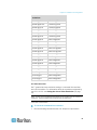
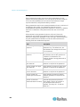
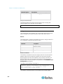
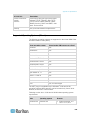
Terminology
Term
Description
Target Server
Server to be accessed remotely via the KX II-101V2 and its connected KVM configuration.
Remote PC
A Windows®, Linux®, or Apple Macintosh® computer
used to access and control target servers
connected to the KX II-101-V2.
Admin serial
port
Use the Admin serial port to connect to the serial
port on the PC using a male DB9 cable. Then use
a standard emulation software package (for
example, HyperTerminal) to access the Admin
serial port. The Admin serial port is used for
network configuration.
Local User port
Enables a user in immediate proximity to the target
server to use the native monitor without unplugging
the KX II-101-V2.
7
Chapter 1: Introduction
Term
Description
Virtual media
Enables a KVM target server to remotely access
media from client PC and network file servers.
Package Contents
Each KX II-101-V2 device ships with:
8
KX II-101-V2 - KVM over IP
KVM cable
Power adapter - AC/DC 5VDC with universal adapter
Mounting bracket kit
Printed Quick Setup Guide
Printed application release notes (if applicable)
Printed technical notes (if applicable)
Chapter 2
Installation and Configuration
In This Chapter
Overview ....................................................................................................9
Default Login Information ..........................................................................9
Getting Started ........................................................................................10
Overview
This chapter describes how to install and configure the KX II-101-V2.
Installation and configuration consists of the following steps:
Step 1: Configure the Target Server (on page 10)
Step 2: Configure Network Firewall Settings (on page 21)
Step 3: Connect the Equipment (on page 22)
Step 4: Configure the KX II-101-V2 (on page 27)
In order to ensure optimum performance, before installing the KX II-101V2 configure the target server you want to access via the KX II-101-V2.
Note that the following configuration requirements apply only to the
target server, not to the computers that you will be using to access the
KX II-101-V2 remotely.
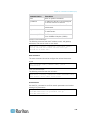
Default Login Information
Default
Value
User name
The default user name is admin. This user has
administrative privileges.
Password
The default password is raritan.
Passwords are case sensitive and must be entered in the
exact case combination in which they were created. For
example, the default password raritan must be entered
entirely in lowercase letters.
The first time you start the KX II-101-V2, you are required
to change the default password.
IP address
The KX II-101-V2 ships with the default IP address of
192.168.0.192.
Important: For backup and business continuity purposes, it is strongly
recommended that you create a backup administrator user name and
password and keep that information in a secure location.
9
Chapter 2: Installation and Configuration
Getting Started
KX II-101-V2 users with Microsoft® Internet Explorer® version 6 or
Windows 2000® must upgrade to Service Pack 4 (SP4) or higher.
The KX II-101-V2 ships with a static default IP address. On a network
without a DHCP server, you must configure a new static IP address, net
mask, and gateway address using either the KX II-101-V2 serial admin
console or the KX II-101-V2 Remote Console.
See Assigning an IP Address (on page 28) for information on assigning
an IP address to the KX II-101-V2 using the Remote Console. See
Configure the KX II-101-V2 Using a Terminal Emulation Program
(Optional) (on page 32) for information on setting an IP address using
the Serial Admin Console.
Step 1: Configure the Target Server
Before installing the KX II-101-V2, first configure the target server you
want to access via the KX II-101-V2 in order to ensure optimum
performance. Note that the following configuration requirements apply
only to the target server, not to the computers that you will be using to
access the KX II-101-V2 remotely.
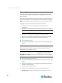
Setting the Server Video Resolution
For optimal bandwidth efficiency and video performance, a target server
running a graphical user interface such as Windows®, X-Windows®,
Solaris™, and KDE should be configured with desktop backgrounds set to
a predominantly solid, light-colored graphic. Backgrounds featuring
photos or complex gradients should be avoided.
Ensure that the server's video resolution and refresh rate are supported
by the KX II-101-V2 and that the signal is non-interlaced. The KX II-101V2 supports these resolutions:
Resolutions
10
640x350 @70Hz
1024x768@85
640x350 @85Hz
1024x768 @75Hz
640x400 @56Hz
1024x768 @90Hz
640x400 @84Hz
1024x768 @100Hz
640x400 @85Hz
1152x864 @60Hz
Chapter 2: Installation and Configuration
Resolutions
640x480 @60Hz
1152x864 @70Hz
640x480 @66.6Hz
1152x864 @75Hz
640x480 @72Hz
1152x864 @85Hz
640x480 @75Hz
1152x870 @75.1Hz
640x480 @85Hz
1152x900 @66Hz
720x400 @70Hz
1152x900 @76Hz
720x400 @84Hz
1280x720@60Hz
720x400 @85Hz
1280x960 @60Hz
800x600 @56Hz
1280x960 @85Hz
800x600 @60Hz
1280x1024 @60Hz
800x600 @70Hz
1280x1024 @75Hz
800x600 @72Hz
1280x1024 @85Hz
800x600 @75Hz
1360x768@60Hz
800x600 @85Hz
1366x768@60Hz
800x600 @90Hz
1368x768@60Hz
800x600 @100Hz
1400x1050@60Hz
832x624 @75.1Hz
1440x900@60Hz
1024x768 @60Hz
1600x1200 @60Hz
1024x768@70
1680x1050@60Hz
1024x768@72
1920x1080@60Hz
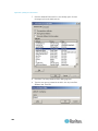
Sun Video Resolution
Sun™ systems have two resolution settings, a command line resolution
and a GUI resolution. For information about the resolutions supported by
the KX II-101-V2, see Setting the Server Video Resolution (on page
10).
Note: If none of the supported resolutions work, make sure the monitor is
multisync. Some monitors will not work with an H&V sync.
Command Line Resolution
To check the command line resolution:
1. Run the following command as the root: # eeprom output-device
11
Chapter 2: Installation and Configuration
To change the command line resolution:
1. Run the following command: # eeprom outputdevice=screen:r1024x768x75 where 1024x768x75 is any resolution
that the KX II-101-V2 supports.
2. Restart the computer.
GUI Resolution/32 Bit
To check the GUI resolution on 32 bit cards:
1. Run the following command: # /usr/sbin/pgxconfig –prconf
To change the GUI resolution on 32 bit cards:
1. Run the following command: # /usr/sbin/pgxconfig –
res1024x768x75 where 1024x768x75 is any resolution that the KX II101-V2 supports.
2. Restart the computer.
GUI Resolution/64 Bit
To check the GUI resolution on 64 bit cards:
1. Run the following command: # /usr/sbin/m64config –prconf
To change the resolution on 64 bit cards:
1. Run the following command: # /usr/sbin/m64config –
res1024x768x75 where 1024x768x75 is any resolution that the KX II101-V2 supports.
2. Restart the computer.
GUI Resolution/Solaris 8
To check the resolution on Solaris™ 8 for 32 bit and 64 bit cards:
1. Run the following command: # /usr/sbin/fbconfig –prconf
To change the resolution on Solaris 8 for 32 and 64 bit cards:
1. Run the following command: # /usr/sbin/fbconfig –res1024x768x75
where 1024x768x75 is any resolution that the KX II-101-V2 supports.
2. Restart the computer.
12
Chapter 2: Installation and Configuration
Mouse Settings
The KX II-101-V2 operates in several mouse modes: Absolute Mouse
Synchronization™, Intelligent Mouse mode and Standard Mouse mode.
Note: Do not use an animated mouse while using Intelligent Mouse
mode.
Mouse parameters do not have to be altered for Absolute Mouse
Synchronization. For both the Standard and Intelligent Mouse modes,
mouse parameters must be set to specific values, which are described in
this section.
Mouse configurations will vary on different target operating systems.
Consult your OS documentation for additional details.
Windows XP, Windows 2003 and Windows 2008 Settings
To configure KVM target servers running Microsoft® Windows
XP® operating system, Windows 2003® operating system or
Windows 2008® operating systems:
1. Configure the mouse settings:
a. Choose Start > Control Panel > Mouse.
b. Click the Pointer Options tab.
c.
In the Motion group:
Set the mouse motion speed setting to exactly the middle
speed.
Disable the "Enhance pointer precision" option.
Disable the Snap To option.
Click OK.
Note: When you are running Windows 2003 on your target server, if
you access the server via KVM and perform any one off the actions
listed below, mouse synchronization may be lost if it has been
previously enabled. You will need to select the Synchronize Mouse
command from the Mouse menu in the client to enable it again.
Following are the actions that may cause this to occur:
- Opening a text editor.
- Accessing the Mouse Properties, Keyboard Properties, and Phone
and Mode Options from the Windows Control Panel.
2. Disable transition effects:
a. Select the Display option from the Control Panel.
b. Click the Appearance tab.
c.
Click Effects.
13
Chapter 2: Installation and Configuration
d. Deselect the "Use the following transition effect for menus and
tooltips" option.
e. Click OK.
3. Close the Control Panel.
Note: For KVM target servers running Windows XP, Windows 2000 or
Windows 2008, you may wish to create a user name that will be used
only for remote connections through the KX II-101-V2. This will enable
you to keep the target server's slow mouse pointer motion/acceleration
settings exclusive to the KX II-101-V2 connection.
Windows XP, 2000, and 2008 login pages revert to preset mouse
parameters that differ from those suggested for optimal KX II-101-V2
performance. As a result, mouse synchronization may not be optimal for
these screens.
Note: Proceed only if you are comfortable adjusting the registry on
Windows KVM target servers. You can obtain better KX II-101-V2 mouse
synchronization at the login pages by using the Windows registry editor
to change the following settings: HKey_USERS\.DEFAULT\Control
Panel\Mouse: > MouseSpeed = 0;MouseThreshold
1=0;MouseThreshold 2=0.
Windows 7 and Windows Vista Settings
To configure KVM target servers running Windows Vista®
operating system:
1. Configure the mouse settings:
a. Choose Start > Settings > Control Panel > Mouse.
b. Select "Advanced system settings" from the left navigation panel.
The System Properties dialog opens.
c.
Click the Pointer Options tab.
d. In the Motion group:
Set the mouse motion speed setting to exactly the middle
speed.
Disable the "Enhanced pointer precision" option.
Click OK.
2. Disable animation and fade effects:
a. Select the System option from the Control Panel.
b. Select Performance Information then Tools > Advanced Tools >
Adjust to adjust the appearance and performance of Windows.
c.
14
Click the Advanced tab.
Chapter 2: Installation and Configuration
d. Click Settings in the Performance group to open the
Performance Options dialog.
e. Under Custom options, deselect the following checkboxes:
Animation options:
Animate controls and elements inside windows
Animate windows when minimizing and maximizing
Fade options:
Fade or slide menus into view
Fade or slide ToolTips into view
Fade out menu items after clicking
3. Click OK and Close the Control Panel.
To configure KVM target servers running Windows 7® operating
system:
1. Configure the mouse settings:
a. Choose Start > Control Panel > Hardware and Sound > Mouse.
b. Click the Pointer Options tab.
c.
In the Motion group:
Set the mouse motion speed setting to exactly the middle
speed.
Disable the "Enhanced pointer precision" option.
Click OK.
2. Disable animation and fade effects:
a. Select Control Panel > System and Security.
b. Select System and then select "Advanced system settings" from
the left navigation panel. The System Properties dialog appears.
c.
Click the Advanced tab.
d. Click the Settings button in the Performance group to open the
Performance Options dialog.
e. Under Custom options, deselect the following checkboxes:
Animation options:
Animate controls and elements inside windows
Animate windows when minimizing and maximizing
Fade options:
15
Chapter 2: Installation and Configuration
Fade or slide menus into view
Fade or slide ToolTips into view
Fade out menu items after clicking
3. Click OK and Close the Control Panel.
Windows 2000 Settings
To configure KVM target servers running Microsoft® Windows
2000® operating system:
1. Configure the mouse settings:
a. Choose Start > Control Panel > Mouse.
b. Click the Motion tab.
Set the acceleration to None.
Set the mouse motion speed setting to exactly the middle
speed.
Click OK.
2. Disable transition effects:
a. Select the Display option from the Control Panel.
b. Click the Effects tab.
Deselect the "Use the following transition effect for menus
and tooltips" option.
3. Click OK and close the Control Panel.
Note: For KVM target servers running Windows XP, Windows 2000 or
Windows 2008, you may wish to create a user name that will be used
only for remote connections through the KX II-101-V2. This will enable
you to keep the target server's slow mouse pointer motion/acceleration
settings exclusive to the KX II-101-V2 connection.
Windows XP, 2000, and 2008 login pages revert to preset mouse
parameters that differ from those suggested for optimal KX II-101-V2
performance. As a result, mouse synchronization may not be optimal for
these screens.
Note: Proceed only if you are comfortable adjusting the registry on
Windows KVM target servers. You can obtain better KX II-101-V2 mouse
synchronization at the login pages by using the Windows registry editor
to change the following settings: HKey_USERS\.DEFAULT\Control
Panel\Mouse: > MouseSpeed = 0;MouseThreshold
1=0;MouseThreshold 2=0.
16
Chapter 2: Installation and Configuration
Linux Settings (Red Hat 4 and 5, and Fedora 14)
Note: The following settings are optimized for Standard Mouse mode
only.
To configure KVM target servers running Linux® (graphical user
interface):
1. Configure the mouse settings:
a. Choose Main Menu > Preferences > Mouse. The Mouse
Preferences dialog appears.
b. Click the Motion tab.
c.
Within the Speed group, set the Acceleration slider to the exact
center.
d. Within the Speed group, set the Sensitivity towards low.
e. Within the Drag & Drop group, set the Threshold towards small.
f.
Close the Mouse Preferences dialog.
Note: If these steps do not work, issue the xset mouse 1 1 command
as described in the Linux command line instructions.
2. Configure the screen resolution:
a. Choose Main Menu > System Settings > Display. The Display
Settings dialog appears.
b. From the Display tab, select a Resolution supported by the KX II101-V2.
c.
From the Advanced tab, verify that the Refresh Rate is
supported by the KX II-101-V2.
Note: Once connected to the target server, in many Linux graphical
environments, the <Ctrl> <Alt> <+> command will change the video
resolution, scrolling through all available resolutions that remain enabled
in the XF86Config or /etc/X11/xorg.conf, depending on your X server
distribution.
To configure KVM target servers running Linux (command line):
1. Set the mouse acceleration to exactly 1 and set the threshold to
exactly 1. Enter this command: xset mouse 1 1. This should be set
for execution upon login.
2. Ensure that each target server running Linux is using a resolution
supported by the KX II-101-V2 at a standard VESA resolution and
refresh rate.
3. Each Linux target server should also be set so the blanking times are
within +/- 40% of VESA standard values:
a. Go to the Xfree86 Configuration file XF86Config.
17
Chapter 2: Installation and Configuration
b. Using a text editor, disable all non-KX II-101-V2 supported
resolutions.
c.
Disable the virtual desktop feature (not supported by the KX II101-V2).
d. Check blanking times (+/- 40% of VESA standard).
e. Restart computer.
Note: If you change the video resolution, you must log off of the target
server and log back in for the video settings to take effect.
Note for Red Hat and Fedora KVM Target Servers
If you are running Red Hat® on the target server using a USB CIM, and
are experiencing problems with the keyboard and/or mouse, there is an
additional configuration setting you can try.
Tip: You might have to perform these steps even after a fresh OS
installation.
To configure Red Hat servers using USB CIMs:
1. Locate the configuration file (usually /etc/modules.conf) in your
system.
2. Using the editor of your choice, make sure that the alias usbcontroller line in the modules.conf file is as follows:
alias usb-controller usb-uhci
Note: If there is another line using usb-uhci in the /etc/modules.conf
file, it needs to be removed or commented out.
3. Save the file.
4. Reboot the system in order for the changes to take effect.
Linux Settings (for Standard Mouse Mode)
Note: The following settings are optimized for Standard Mouse mode
only.
To configure KVM target servers running Linux® (graphical user
interface):
1. Configure the mouse settings:
a. Red Hat 5 users, choose Main Menu > Preferences > Mouse.
Red Hat 4 users, choose System > Preferences > Mouse. The
Mouse Preferences dialog appears.
b. Click on the Motion tab.
18
Chapter 2: Installation and Configuration
c.
Within the Speed group, set the Acceleration slider to the exact
center.
d. Within the Speed group, set the Sensitivity towards low.
e. Within the Drag & Drop group, set the Threshold towards small.
f.
Close the Mouse Preferences dialog.
Note: If these steps do not work, issue the xset mouse 1 1 command
as described in the Linux command line instructions.
2. Configure the screen resolution:
a. Choose Main Menu > System Settings > Display. The Display
Settings dialog appears.
b. On the Settings tab, select a Resolution supported by the KX II101-V2.
c.
Click OK.
Note: Once connected to the target server, in many Linux graphical
environments, the <Ctrl> <Alt> <+> command will change the video
resolution, scrolling through all available resolutions that remain enabled
in the XF86Config or /etc/X11/xorg.conf, depending on your X server
distribution
Note: If you change the video resolution, you must log out of the target
server and log back in for the video settings to take effect.
Sun Solaris Settings
A Solaris™ target server must be configured to one of the display
resolutions supported by the KX II-101-V2. The most popular supported
resolutions for Sun™ machines are:
Resolution
1024x768@60Hz
1024x768@70Hz
1024x768@75Hz
1024x768@85Hz
1280x1024@60Hz
19
Chapter 2: Installation and Configuration
Set the mouse acceleration value to exactly 1 and the threshold to
exactly 1. A target server running the Solaris operating system must
output VGA video (H-and-V sync, not composite sync). Set this at the
graphical user interface or with the command line xset mouse a t where
a is the acceleration and t is the threshold.
To change your Sun video card output from composite sync to
the non-default VGA output:
1. Issue the Stop+A command to drop to bootprom mode.
2. Issue the #eeprom output-device=screen:r1024x768x75 command to
change the output resolution.
3. Issue the boot command to reboot the server.
Alternatively, contact your Raritan representative to purchase a video
output adapter. Suns with composite sync output require APSSUN II
Raritan guardian for use with the KX II-101-V2. HD15 Suns with separate
sync output require an APKMSUN Raritan guardian for use with the KX
II-101-V2.
Apple Macintosh Settings
Mac® works with the KX II-101-V2 'out of the box.' However, you must
use Absolute Mouse Synchronization and enable Absolute Mouse mode
and mouse scaling for Mac servers on the KX II-101-V2 Port page.
To enable this setting:
1. Choose Device Settings > Port Configuration. The Port Configuration
Page opens.
2. Click the Port Name for the port you want to edit.
3. In the USB Connection Settings section, select the Enable Absolute
Mouse checkbox and the "Enable Absolute mouse scaling for MAC
server" checkbox. Click OK.
See Port Configuration (on page 126).
IBM AIX Settings
1. Go to the Style Manager.
20
Chapter 2: Installation and Configuration
2. Click on Mouse Settings and set the Mouse Acceleration to 1.0 and
Threshold to 3.0.
Step 2: Configure Network Firewall Settings
To access the KX II-101-V2 through a network firewall, your firewall must
allow communication on TCP Port 5000. Alternatively, the KX II-101-V2
can be configured to use a different TCP port of your own designation.
To take advantage of the KX II-101-V2's web-access capabilities, the
firewall must allow inbound communication on TCP Port 443 - the
standard TCP port for HTTPS communication. To take advantage of the
KX II-101-V2's redirection of HTTP requests to HTTPS (so that users
may type the more common, http://xxx.xxx.xxx.xxx, instead of
https://xxx.xxx.xxx.xxx), the firewall must also allow inbound
communication on TCP Port 80 - the standard TCP port for HTTP
communication.
21
Chapter 2: Installation and Configuration
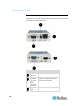
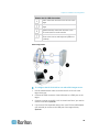
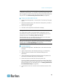
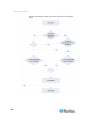
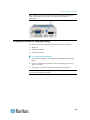
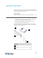
Step 3: Connect the Equipment
The KX II-101-V2 has the physical connections described in the diagram.
Each letter in the diagram corresponds to a step in the equipment
connection process described here.
Diagram key
Power
connector
Single power adapter.
KVM cable Attach the supplied KVM cable
with monitor, to the target server's keyboard,
PS/2 and
video and mouse ports
USB
connectors
(included)
Ethernet
LAN
22
Provides LAN connectivity.
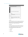
Chapter 2: Installation and Configuration
Diagram key
Admin port
Local user
Use to do one of the following:
Configure and manage the
device with a terminal
emulation program on your
PC.
Configure and manage a
power strip (requires an
adapter, not included).
Connect an external modem
to dial into the device.
The local port connects to a
monitor.
A: Power
The KX II-101-V2 is powered by a 100-240V AC input and 5VDC output
power adaptor that is included with the device. For standard AC power,
plug the included AC power adaptor into the Power port and plug the
other end into a nearby AC power outlet.
B: Target Server
Use either the PS/2 or USB to connect to the target. Before connecting,
configure your target server's video to a supported resolution. Use the
USB connection if you are using virtual media or Absolute Mouse Mode.
23
Chapter 2: Installation and Configuration
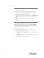
USB Configuration
To configure the KX II-101-V2 for use with a USB target server:
1. Use the attached video cable to connect the KX II-101-V2 to the
target video port.
2. Connect the USB connector of the KVM cable to the KX II-101-V2
and to a USB port on the target server.
3. Connect a monitor to the KX II-101-V2 Local User Port if you need to
use the local video. Optional
4. Connect the USB keyboard and mouse directly to the target.
Optional
Note: If you are using virtual media, you must use the USB
connection.
Diagram key for USB Connection
KX II-101-V2
Target server
Local monitor (optional)
Local mouse and keyboard (optional)
24
Chapter 2: Installation and Configuration
Diagram key for USB Connection
Video connection from the KX II-101-V2 to the
target
USB connection from the KX II-101-V2 to the
target
Optional monitor connection from KX II-101V2 Local User Port to the monitor
Optional USB connection from the target
server to the mouse and keyboard (cable not
included)
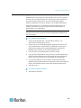
PS/2 Configuration
To configure the KX II-101-V2 for use with a PS/2 target server:
1. Use the attached video cable to connect the KX II-101-V2 to the
target video port.
2. Connect the PS/2 connector of the KVM cable to a PS/2 port on the
target.
3. Connect a monitor to the KX II-101-V2 Local User Port if you need to
use the local video. Optional
4. If you have a PS/2 keyboard and mouse, use a PS/2 to USB adapter
(not included) to connect to the USB port of the target directly.
Optional
25
Chapter 2: Installation and Configuration
Note: If you are using virtual media, you must use the USB connection.
Diagram key for PS/2 connections
KX II-101-V2
Target server
Local monitor
Local mouse and keyboard (optional)
Video connection from the KX II-101-V2 to the
target
KVM cable connection from the KX II-101-V2
to the target server
Optional KX II-101-V2 to monitor connection
Optional PS/2 to USB adapter connection
(cable not included) from target to keyboard
and mouse
C: Network
Connect a standard Ethernet cable from the network port labeled LAN to
an Ethernet switch, hub or router. The LAN LEDs that appear above the
Ethernet connection indicate Ethernet activity. The yellow one blinks
while the KX II-101-V2 is in use, indicating IP traffic at 10 Mbps. The
green light indicates a 100 Mbps connection speed.
D: Admin Port
The Admin port enables you to perform configuration and setup for the
KX II-101-V2 using a terminal emulation program like HyperTerminal.
Use one DB9M to DB9F straight serial cable to connect from the KX II101-V2 to the serial port on your PC or laptop. The serial port
communication settings should be configured as follows:
26
115,200 Baud
8 data bits
1 stop bit
No parity
No flow control
Chapter 2: Installation and Configuration
E: Local User Port
The Local User port serves as a pass-through to the target server video
so that it connects directly to the monitor. The local keyboard and mouse
must be connected to target server directly.
For USB configurations, only the local video connects to the target server
at the Local User port. The keyboard and mouse connect directly to the
target server using USB ports.
Step 4: Configure the KX II-101-V2
Note: You must use a crossover cable between the KX II-101-V2 and
client if you are configuring the KX II-101-V2 through a web browser.
Configure the KX II-101-V2 Using the Remote Console
The KX II-101-V2 Remote Console is a web-based application that
enables you to configure the device prior to use and manage it after it
has been configured. Before configuring the KX II-101-V2 using the
Remote Console, you must have both your workstation and the device
connected to a network.
You can also use a terminal emulation program to configure the KX II101-V2. See Configure the KX II-101-V2 Using a Terminal Emulation
Program (Optional) (on page 32).
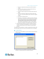
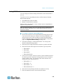
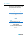
Setting a New Password
When you first log into the Remote Console, you are prompted to set a
new password to replace the default. Then you can configure the KX II101-V2.
1. Log into a workstation with network connectivity to your KX II-101-V2
device.
2. Launch a supported web browser such as Internet Explorer ® (IE) or
Firefox®.
3. In the address field of the browser, enter the default IP address of
the device: 192.168.0.192.
4. Press Enter. The login page opens.
5. Enter the user name admin and the password raritan.
6. Click Login. The Change Password page is displayed.
7. Type raritan in the Old Password field.
8. Type a new password in the New Password field and the Confirm
New Password field. Passwords can be up to 64 characters long and
can consist of English alphanumeric and printable special
characters.
27
Chapter 2: Installation and Configuration
9. Click Apply. You will receive confirmation that the password was
successfully changed.
10. Click OK. The Port Access page opens.
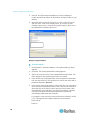
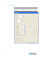
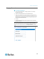
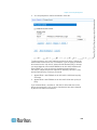
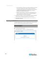
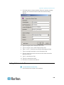
Assigning an IP Address
These procedures describe how to assign an IP address on the Network
Settings page. For complete information about all of the fields and the
operation of this page, see Network Settings (on page 106).
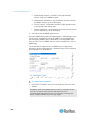
To assign an IP address:
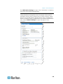
1. Choose Device Settings > Network. The Network Settings page
opens.
2. Specify a meaningful Device Name for your KX II-101-V2 device. Up
to 32 alphanumeric characters using valid special characters and no
spaces.
3. In the IPv4 section, enter or select the appropriate IPv4-specific
network settings:
a. Enter the IP Address if needed. The default IP address is
192.168.0.192.
b. Enter the Subnet Mask. The default subnet mask is
255.255.255.0.
c.
Enter the Default Gateway if None is selected from the IP Auto
Configuration drop-down.
d. Enter the Preferred DHCP Host Name if DHCP is selected from
the IP Auto Configuration drop-down.
e. Select the IP Auto Configuration. The following options are
available:
None (Static IP) - This option requires that you manually specify
the network parameters.
This is the recommended option because the KX II-101-V2 is an
infrastructure device and its IP address should not change.
DHCP - Dynamic Host Configuration Protocol is used by
networked computers (clients) to obtain unique IP addresses
and other parameters from a DHCP server.
With this option, network parameters are assigned by the DHCP
server. If DHCP is used, enter the Preferred host name (DHCP
only). Up to 63 characters.
4. If IPv6 is to be used, enter or select the appropriate IPv6-specific
network settings in the IPv6 section:
a. Select the IPv6 checkbox to activate the fields in the section.
b. Enter a Global/Unique IP Address. This is the IP address
assigned to the KX II-101-V2.
28
Chapter 2: Installation and Configuration
c.
Enter the Prefix Length. This is the number of bits used in the
IPv6 address.
d. Enter the Gateway IP Address.
e. Link-Local IP Address. This address is automatically assigned to
the device. It is used for neighbor discovery or when no routers
are present. Read-Only
f.
Zone ID. This identifies the device with which the address is
associated. Read-Only
g. Select the IP Auto Configuration. The following options are
available:
None - Use this option if you do not want an auto IP configuration
and prefer to set the IP address yourself (static IP). This is the
default and recommended option.
If None is selected for the IP auto configuration, the following
Network Basic Settings fields are enabled: Global/Unique IP
Address, Prefix Length, and Gateway IP Address allowing you to
manually set the IP configuration.
Router Discovery - Use this option to automatically assign IPv6
addresses that have Global or Unique Local significance beyond
that of the Link Local, which only applies to a directly connected
subnet.
5. Select Obtain DNS Server Address Automatically if DHCP is
selected and Obtain DNS Server Address is enabled. When Obtain
DNS Server Address Automatically is selected, the DNS information
provided by the DHCP server will be used.
6. If Use the Following DNS Server Addresses is selected, regardless
of whether DHCP is selected or not, the addresses entered in this
section will be used to connect to the DNS server.
Enter the following information if the Following DNS Server
Addresses option is selected. These addresses are the primary and
secondary DNS addresses that will be used if the primary DNS
server connection is lost due to an outage.
a. Primary DNS Server IP Address
b. Secondary DNS Server IP Address
7. When finished, click OK.
29
Chapter 2: Installation and Configuration
See LAN Interface Settings (on page 110) for information in configuring
this section of the Network Settings page.
Note: In some environments, the default LAN Interface Speed & Duplex
setting Autodetect (autonegotiator) does not properly set the network
parameters, which results in network issues. In these instances, setting
the KX II-101-V2 LAN Interface Speed & Duplex field to 100 Mbps/Full
Duplex (or whatever option is appropriate to your network) addresses the
issue. See the Network Settings (on page 106) page for more
information.
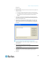
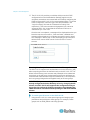
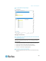
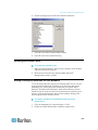
Naming the Target Server
1. Attach the KX II-101-V2 to the target server.
2. Choose Device Settings > Port Configuration. The Port Configuration
page opens.
3. Click the Port Name for the target server. The Port page opens.
4. Type a name, up to 32 alphanumeric and special characters.
5. Click OK.
30
Chapter 2: Installation and Configuration
Remote Authentication
Note to CC-SG Users
When the KX II-101-V2 is controlled by CommandCenter Secure
Gateway, CC-SG authenticates users and groups.
For additional information about CC-SG authentication, see the
CommandCenter Secure Gateway User Guide, Administrator Guide,
or Deployment Guide, which can be downloaded from the Support
section of the Raritan website (www.raritan.com).
Supported Protocols
To simplify management of usernames and passwords, the KX II-101-V2
provides the ability to forward authentication requests to an external
authentication server. Two external authentication protocols are
supported: LDAP/LDAPS and RADIUS.
Note on Microsoft Active Directory
Microsoft® Active Directory® uses the LDAP/LDAPS protocol natively, and
can function as an LDAP/LDAPS server and authentication source for
the KX II-101-V2. If it has the IAS (Internet Authorization Server)
component, a Microsoft Active Directory server can also serve as a
RADIUS authentication source.
Create User Groups and Users
As part of the initial configuration, you must define user groups and users
in order for users to access the KX II-101-V2.
The KX II-101-V2 uses system-supplied default user groups and allows
you to create groups and specify the appropriate permissions to suit your
needs.
User names and passwords are required to gain access to the KX II-101V2. This information is used to authenticate users attempting to access
your KX II-101-V2. See User Management (on page 83) for details on
adding and editing user groups and users.
31
Chapter 2: Installation and Configuration
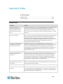
Configure the KX II-101-V2 Using a Terminal Emulation Program (Optional)
You can use the Admin serial console with a terminal emulation program
like HyperTerminal to set the following configuration parameters for the
KX II-101-V2:
IP address
Subnet mask address
Gateway address
IP autoconfiguration
LAN speed
LAN interface mode
To use a terminal emulation program with the KX II-101-V2, you must
first connect the included RS-232 serial cable from the Admin port on the
KX II-101-V2 to a COM port on your PC.
For demonstration purposes, the terminal emulation program described
in this section is HyperTerminal. You can use any terminal emulation
program.
To use a terminal emulation program to configure the KX II-101V2:
1. Connect the KX II-101-V2 to a local PC.
2. Connect to the Admin port on the KX II-101-V2 and the COM1 port
on the PC.
3. Launch the terminal emulation program you want to use to configure
the KX II-101-V2.
4. Set the following port settings in the terminal emulation program:
Bits per second - 115200
Data bits - 8
Parity - None
Stop bits - 1
Flow control - None
5. Connect to the KX II-101-V2. The login page opens.
6. Type the administrator username and press Enter. You are prompted
to enter your password.
7. Type the default administrator name admin and press Enter. You are
promoted to enter your password.
8. At the Admin Port > prompt, type config and press Enter.
9. At the Config > prompt, type network and press Enter.
32
Chapter 2: Installation and Configuration
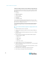
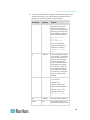
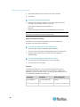
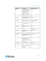
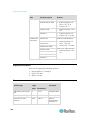
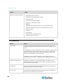
10. To configure new network settings, at the Network prompt, type
interface followed by one of the following commands and its
appropriate argument (option), then press Enter.
Command
Argument
Options
ipauto
none|dhcp
none - Enables you to
manually specify an IP
address for the device.
You must follow this option
with the ip command and
the IP address, as shown
in the following example:
interface ipauto
none ip
192.168.50.12
dhcp - Automatically
assign an IP address to
the device on startup.
interface ipauto
dhcp
ip
IP address
The IP address to assign
to the device. To manually
set an IP address for the
first time, this command
must be used with the
ipauto command and the
none option. See ipauto
for information. After you
have manually assigned
an IP address once, you
can use the ip command
alone to change the IP
address.
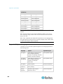
mask
subnet mask
Command column should
be "interface"
interface | ip | ...
interface | mask | The
subnet mask IP address
interface | gw | The
gateway IP address
interface | mode
....
|
gw
IP address
The gateway IP address
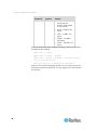
mode
mode
The Ethernet mode. You
have the following choices:
33
Chapter 2: Installation and Configuration
Command
Argument
Options
auto - Automatically
sets speed and
interface mode based
on the network.
10hdx - 10 MB/s, half
duplex.
10fdx - 10 MB/s, full
duplex
100hdx - 100 MB/s,
half duplex
100fdx - 100 MB/s, full
duplex
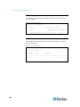
When you have successfully changed a setting, you see a confirmation
message like the following:
Admin Port > config
Admin Port > Config > network
Admin Port > Config > Network > interface ipauto
none ip 192.168.50.126
Network interface configuration successful.
When you are finished configuring the KX II-101-V2, type logout at the
command prompt and press Enter. You are logged out of the command
line interface.
34
Chapter 3
Working with Target Servers
In This Chapter
Interfaces .................................................................................................35
Virtual KVM Client (VKC) .........................................................................44
Interfaces
KX II-101-V2 Remote Console Interface
The KX II-101-V2 Remote Console is a browser-based graphical user
interface that allows you to log into KVM target servers and serial targets
connected to the KX II-101-V2 and to remotely administer the KX II-101V2.
The KX II-101-V2 Remote Console provides a digital connection to your
connected KVM target servers. When you log into a KVM target server
using the KX II-101-V2 Remote Console, a Virtual KVM Client window
opens.
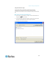
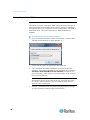
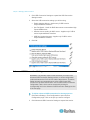
Note: If you are using Internet Explorer® 7, you may run into permission
issues when trying to connect to a target server. To avoid this, do the
following:
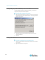
1. In Internet Explorer, click Tools > Internet Options to open the Internet
Options dialog.
2. In the "Temporary Internet files" section, click Settings. The Settings
dialog opens.
3. In the "Check for newer versions of stored pages" section, select
Automatically.
4. Click OK to apply the settings.
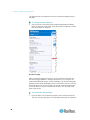
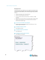
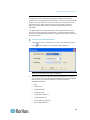
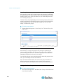
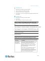
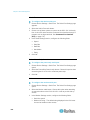
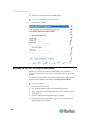
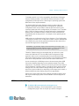
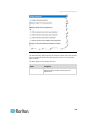
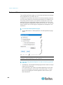
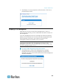
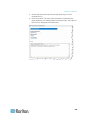
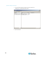
Enable Direct Port Access
Direct port access enables you to access the KX II-101-V2 Remote
Client without having to go through the usual login page. With direct port
access enabled, you can define an URL to navigate directly to the Port
Access page.
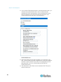
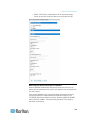
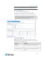
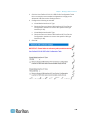
To enable direct port access:
1. Launch the KX II-101-V2 Remote Console.
2. Choose Device Settings > Device Services. The Device Services
page opens.
35
Chapter 3: Working with Target Servers
3. Select the Enable Direct Port Access via URL checkbox.
4. Click Save.
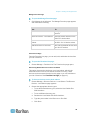
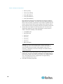
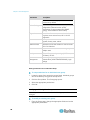
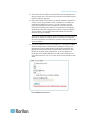
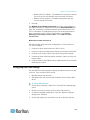
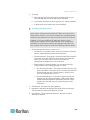
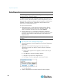
To define a direct port access URL:
Define a URL with the IP address, user name, password, and if
necessary, port number of the KX II-101-V2.
The format for a direct port access URL is:
https://IP
address/dpa.asp?username=username&password=password
Tip: Define a direct port access URL once, then save it in your web
browser as a bookmark to make reusing it easier.
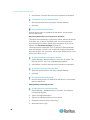
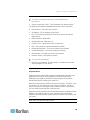
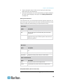
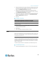
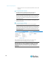
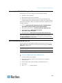
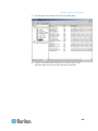
KX II-101-V2 Console Navigation
The KX II-101-V2 Console interfaces provide many methods for
navigation and making your selections.
To select an option (use any of the following):
Click on a tab. A page of available options appears.
Hover over a tab and select the appropriate option from the menu.
Click the option directly from the menu hierarchy displayed
(breadcrumbs).
To scroll through pages longer than the screen:
Use Page Up and Page Down keys on your keyboard.
Use the scroll bar on the right.
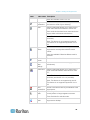
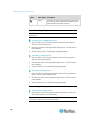
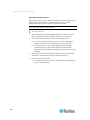
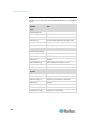
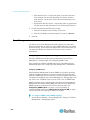
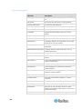
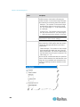
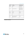
Left Panel
The left panel of the KX II-101-V2 interface contains the following
information. Note that some information is conditional - meaning it is
displayed if you are a certain of user, are using certain features, and so
on. Conditional information is noted here.
36
Information
Description
When displayed?
Time & Session
The current date and
time.
Always
User
Username of current user Always
Chapter 3: Working with Target Servers
Information
Description
When displayed?
State
The current state of the
application, either idle or
active. If idle, the
application tracks and
displays the time the
session has been idle.
Always
Your IP
The IP address used to
access the KX II-101-V2.
Always
Last Login
The last login date and
time of current user.
Always
Under CC-SG
Management
The IP address of the
CC-SG device managing
the KX II-101-V2.
When the KX II-101-V2
is being managed by
CC-SG
Device Information
Information specific to the Always
KX II-101-V2 you are
using.
Device Name
Name assigned to the
device.
IP Address
The IP address of the KX Always IPv4, and IPv6 if
II-101-V2.
it is configured
Firmware
Current version of
firmware.
Device Model
Model of the KX II-101-V2 Always
Port States
The statuses of the port
being used by the KX II101-V2.
Connect Users
The users, identified by
Always
their username and IP
address, who are
currently connected to the
KX II-101-V2.
Online Help
Links to online help.
Always
Favorite Devices
See Managing Favorites.
Always
FIPS Mode
FIPS Mode: EnabledSSL
Certificate: FIPS Mode
Compliant
When FIPS is enabled
Always
Always
Always
37
Chapter 3: Working with Target Servers
The left panel can be collapsed in order to increase the display area of
the page.
To collapse and the left panel:
Click on the blue, left-facing arrow located approximately halfway
down the left side of the panel. Once the panel is collapsed, click the
blue arrow again to expand it.
Port Access Page
After successfully logging in to the KX II-101-V2 Remote Console, the
Port Access page appears. This page lists the KX II-101-V2 port, the
connected KVM target server, and its availability. The Port Access page
provides access to the KVM target server connected to the KX II-101-V2.
A KVM target server is a server that you want to control through the KX
II-101-V2 device. They are connected to the KX II-101-V2 ports at the
back of the device.
To use the Port Access page:
1. From the KX II-101-V2 Remote Console, click the Port Access tab.
The Port Access page opens. The following information is displayed:
38
Chapter 3: Working with Target Servers
Port Name - The name of the KX II-101-V2 port. Initially, this is
set to Dominion_KX2_101_Port1 but you can change the name
to something more descriptive. When you click a Port Name link,
the Port Action Menu appears.
Availability - The Availability can be Idle, Connected or Busy.
2. Click the Port Name of the target server you want to access. The
Port Action Menu appears. See Port Action Menu (on page 39) for
details on available menu options.
3. Choose the desired menu command from the Port Action Menu.
Port Action Menu
When you click a Port Name in the Port Access list, the Port Action menu
appears. Choose the desired menu option for that port to execute it. Note
that only currently available options, depending on the port's status and
availability, are listed in the Port Action menu:
Connect - Creates a new connection to the target server. For the KX
II-101-V2 Remote Console, a new Virtual KVM Client (VKC) (on
page 44) page appears.
Disconnect - Disconnects this port and closes the Virtual KVM Client
page for this target server. This menu item is available only when the
port status is up and connected, or up and busy.
Power On - Powers on the target server through the associated
outlet. This option is visible only when there are one or more power
associations to the target, and when the user has permission to
operate this service.
Power Off - Powers off the target server through the associated
outlets. This option is visible only when there are one or more power
associations to the target, when the target power is on (port status is
up), and when user has permission to operate this service.
Power Cycle - Power cycles the target server through the associated
outlets. This option is visible only when there are one or more power
associations to the target, and when the user has permission to
operate this service.
39
Chapter 3: Working with Target Servers
Managing Favorites
A Favorites feature is provided so you can organize and quickly access
the devices you use frequently. The Favorite Devices section is located
in the lower left side (sidebar) of the Port Access page and provides the
ability to:
Create and manage a list of favorite devices
Quickly access frequently-used devices
List your favorites either by Device Name, IP Address, or DNS
hostname
Discover KX II-101-V2 devices on its subnet (before and after login)
Retrieve discovered KX II-101-V2 devices from the connected
Dominion device (after login)
To access a favorite KX II-101-V2 device:
Click the device name (listed beneath Favorite Devices). A new
browser opens to that device.
To display favorites by name:
Click Display by Name.
To display favorites by IP Address:
Click Display by IP.
To display favorites by the host name:
40
Click Display by Host Name.
Chapter 3: Working with Target Servers
Manage Favorites Page
To open the Manage Favorites page:
Click Manage in the left panel. The Manage Favorites page appears
and contains the following:
Use:
To:
Favorites List
Manage your list of favorite
devices.
Discover Devices - Local Subnet
Discover Raritan devices on the
client PC's local subnet.
Discover Devices - KX II-101-V2
Subnet
Discover the Raritan devices on
the KX II-101-V2 device subnet.
Add New Device to Favorites
Add, edit, and delete devices from
your list of Favorites.
Favorites List Page
From the Favorites List page, you can add, edit, and delete devices from
your list of favorites.
To open the Favorites List page:
Choose Manage > Favorites List. The Favorites List page opens.
Discovering Raritan Devices on the Local Subnet
This option discovers the devices on your local subnet, which is the
subnet where the KX II-101-V2 Remote Console is running. These
devices can be accessed directly from this page or you can add them to
your list of favorites. See Favorites List Page (on page 41).
To discover devices on the local subnet:
1. Choose Manage > Discover Devices - Local Subnet. The Discover
Devices - Local Subnet page appears.
2. Choose the appropriate discovery port:
To use the default discovery port, select the Use Default Port
5000 checkbox.
To use a different discovery port:
a. Deselect the Use Default Port 5000 checkbox.
b. Type the port number in the Discover on Port field.
c.
Click Save.
41
Chapter 3: Working with Target Servers
3. Click Refresh. The list of devices on the local subnet is refreshed.
To add devices to your Favorites List:
1. Select the checkbox next to the device name/IP address.
2. Click Add.
To access a discovered device:
Click the device name or IP address for that device. A new browser
opens to that device.
Discovering Raritan Devices on the KX II-101-V2 Subnet
This option discovers devices on the device subnet, which is the subnet
of the KX II-101-V2 device IP address itself. You can access these
devices directly from this the Subnet page or add them to your list of
favorites. See Favorites List Page (on page 41).
This feature allows multiple KX II-101-V2 devices to interoperate and
scale automatically. The KX II-101-V2 Remote Console automatically
discovers the KX II-101-V2 devices, and any other Raritan device, in the
subnet of the KX II-101-V2.
To discover devices on the device subnet:
1. Choose Manage > Discover Devices - KX II-101-V2 Subnet. The
Discover Devices - KX II-101-V2 Subnet page appears.
2. Click Refresh. The list of devices on the local subnet is refreshed.
To add devices to your Favorites List:
1. Select the checkbox next to the device name/IP address.
2. Click Add.
To access a discovered device:
Click the device name or IP address for that device. A new browser
opens to that device.
Adding, Editing and Deleting Favorites
To add a device to your favorites list:
1. Choose Manage > Add New Device to Favorites. The Add New
Favorite page appears.
2. Type a meaningful description.
3. Type the IP Address/Host Name for the device.
4. Change the discovery Port (if necessary).
5. Select the Product Type.
42
Chapter 3: Working with Target Servers
6. Click OK. The device is added to your list of favorites.
To edit a favorite:
1. From the Favorites List page, select the checkbox next to the
appropriate KX II-101-V2 device.
2. Click Edit. The Edit page appears.
3. Update the fields as necessary:
Description
IP Address/Host Name - Type the IP address of the KX II-101-V2
device
Port (if necessary)
Product Type
4. Click OK.
To delete a favorite:
Important: Exercise caution in the removal of favorites. You are not
prompted to confirm their deletion.
1. Select the checkbox next to the appropriate KX II-101-V2 device.
2. Click Delete. The favorite is removed from your list of favorites.
Logging Out
To quit the KX II-101-V2:
Click Logout in the upper right-hand corner of the page.
Note: Logging out also closes any open Virtual KVM Client and serial
client sessions.
Multi-Platform Client (MPC)
Raritan Multi-Platform Client (MPC) is a graphical user interface for the
Raritan product lines, providing remote access to target servers
connected to Raritan KVM over IP devices. For details on using MPC,
see the KVM and Serial Access Clients Guide available on Raritan's
website on the same page as the user guide. Instructions on launching
MPC are provided there.
Please note this client is used by various Raritan products. As such,
references to other products may appear in this section of help.
43
Chapter 3: Working with Target Servers
Virtual KVM Client (VKC)
Please note this client is used by various Raritan products. As such,
references to other products may appear in this section of help.
Overview
Whenever you access a target server using the Remote Console, a
Virtual KVM Client (VKC) window opens. There is one Virtual KVM Client
for the target server you are connected to. This windows is accessed via
the Windows® task bar.
Virtual KVM Client windows can be minimized, maximized, and moved
around your computer desktop.
Note: Refreshing your HTML browser closes the Virtual KVM Client
connection, so exercise caution.
Note: If you are using Firefox 3.0.3, you may experience problems
launching the application. If this occurs, clear the browser cache and
launch the application again.
Connecting to a KVM Target Server
To connect to a KVM target server:
1. From the KX II-101-V2 Remote Console, click the Port Access tab to
open it. The Port Access page opens.
2. Click the Port Name of the target you want to access. The Port
Action menu appears.
3. Click Connect. A Virtual KVM Client window opens to the target
server connected to that port.
Toolbar Buttons and Status Bar Icons
Button
Button name Description
Connection
Properties
Opens the Modify Connection Properties dialog
from which you can manually adjust bandwidth
options (such as connection speed, color depth,
smoothing, and so forth).
Video
Settings
Opens the Video Settings dialog, allowing you to
manually adjust video conversion parameters.
Color
Calibration
Adjusts color settings to reduce excess color
noise.
Same as choosing Video > Color Calibrate.
44
Chapter 3: Working with Target Servers
Button
Button name Description
Note: Not available in KX II-101-V2.
Target
Screenshot
Click to take a screenshot of the target server
and save it to a file of your choosing.
Audio
Opens a dialog that allows you to select from a
list of audio devices connected to a client PC.
Once audio devices have been connected to the
target, select to disconnect the devices.
Note: This feature is available with the KX II 2.4.0
(and later).
Note: This feature is not supported by the LX.
This feature is not supported by the KX II-101V2.
Synchronize
Mouse
Dual-mouse mode forces the realignment of the
target server mouse pointer with the mouse
pointer.
Note: Not available if Absolute Mouse mode is
selected.
Refresh
Screen
Forces a refresh of the video screen.
Auto-sense
Video
Settings
Forces a refresh of the video settings (resolution,
refresh rate).
Smart Card
Opens a dialog that allows you to select from a
list of smart card readers connected to a client
PC.
Note: This feature is available on the KSX II 2.3.0
(and later) and the KX II 2.1.10 (and later).
Note: This feature is not supported by the LX.
This feature is not supported by the KX II-101V2.
Send
Ctrl+Alt+Del
Sends a Ctrl+Alt+Del hot key combination to the
target server.
Single Cursor Starts Single Cursor mode in which the local
Mode
mouse pointer no longer appears onscreen.
Press Ctrl+Alt+O to exit this mode.
Full Screen
Mode
Maximizes the screen real estate to view the
target server desktop.
45
Chapter 3: Working with Target Servers
Button
Button name Description
Scaling
Increases or reduces the target video size so you
can view the entire contents of the target server
window without using the scroll bar.
Power Controlling a Target Server
Note: These features are available only when you have made power
associations.
To power cycle a KVM target server:
1. From the KX II-101-V2 Remote Console, click the Port Access tab.
The Port Access page opens.
2. Click the Port Name of the appropriate target server. The Port Action
menu appears.
3. Choose Power Cycle. A confirmation message appears.
To power on a target server:
1. From the KX II-101-V2 Remote Console, click the Port Access tab.
The Port Access page opens.
2. Click the port name of the appropriate target server. The Port Action
menu appears.
3. Choose Power On. A confirmation message appears.
To power off a target server:
1. From the KX II-101-V2 Remote Console, click the Port Access tab to
open it. The Port Access page opens.
2. Click the port name of the appropriate target server. The Port Action
menu appears.
3. Choose Power Off. A confirmation message appears.
Disconnecting KVM Target Servers
To disconnect a target server:
Click the port name of the target you want to disconnect. When Port
Action menu appears, click Disconnect.
Tip: You can also close the Virtual KVM Client window by selecting
Connection > Exit from the Virtual KVM menu.
46
Chapter 3: Working with Target Servers
Connection Properties
The dynamic video compression algorithms maintain KVM console
usability under varying bandwidth constraints. The devices optimize KVM
output not only for LAN use, but also for WAN use. These devices can
also control color depth and limit video output, offering an optimal
balance between video quality and system responsiveness for any
bandwidth.
The parameters in the Properties dialog can be optimized to suit your
needs for different operating environments. Connection properties are
saved across subsequent connections to generation 2 devices once they
are set and saved.
To set the connection properties:
1. Choose Connection > Properties or click the Connection Properties
button
in the toolbar. The Properties dialog appears.
Note: KX II-101 does not support 1G Ethernet.
2. Choose the Connection Speed from the drop-down list. The device
can automatically detect available bandwidth and not limit bandwidth
use. However, you can also adjust this usage according to
bandwidth limitations.
Auto
1G Ethernet
100 Mb Ethernet
10 Mb Ethernet
1.5 Mb (MAX DSL/T1)
1 Mb (Fast DSL/T1)
512 Kb (Medium DSL/T1)
384 Kb (Slow DSL/T1)
47
Chapter 3: Working with Target Servers
256 Kb (Cable)
128 Kb (Dual ISDN)
56 kb (ISP Modem)
33 kb (Fast Modem)
24 kb (Slow Modem)
Note that these settings are an optimization for specific conditions
rather than an exact speed. The client and server always attempt to
deliver video as quickly as possible on the network regardless of the
current network speed and encoding setting. But the system will be
most responsive when the settings match the real world environment.
3. Choose the Color Depth from the drop-down list. The device can
dynamically adapt the color depth transmitted to remote users in
order to maximize usability in all bandwidths.
15-bit RGB Color
8-bit RGB Color
4-bit Color
4-bit Gray
3-bit Gray
2-bit Gray
Black and White
Important: For most administrative tasks (server monitoring,
reconfiguring, and so on), the full 24-bit or 32-bit color spectrum
made available by most modern video graphics cards is not
necessary. Attempting to transmit such high color depths wastes
network bandwidth.
4. Use the slider to select the desired level of Smoothing (15-bit color
mode only). The level of smoothing determines how aggressively to
blend screen regions with small color variation into a single smooth
color. Smoothing improves the appearance of target video by
reducing displayed video noise.
5. Click OK to set these properties.
48
Chapter 3: Working with Target Servers
Connection Information
To obtain information about your Virtual KVM Client
connection:
Choose Connection > Info... The Connection Info window opens.
The following information is displayed about the current connection:
Device Name - The name of the device.
IP Address - The IP address of the device.
Port - The KVM communication TCP/IP port used to access the
target device.
Data In/Second - Data rate in.
Data Out/Second - Data rate out.
Connect Time - The duration of the connect time.
FPS - The frames per second transmitted for video.
Horizontal Resolution - The screen resolution horizontally.
Vertical Resolution - The screen resolution vertically.
Refresh Rate - How often the screen is refreshed.
Protocol Version - RFB protocol version.
To copy this information:
Click Copy to Clipboard. The information is available to be pasted
into the program of your choice.
Keyboard Options
Keyboard Macros
Keyboard macros ensure that keystroke combinations intended for the
target server are sent to and interpreted only by the target server.
Otherwise, they might be interpreted by the computer on which the
Virtual KVM Client is running (your client PC).
Macros are stored on the client PC and are PC-specific. Therefore, if you
use another PC, you cannot see your macros. In addition, if another
person uses your PC and logs in under a different name, that user will
see your macros since they are computer-wide.
Keyboard macros created in the Virtual KVM Client are available in MultiPlatform Client (MPC) and vice versa. However, keyboard macros
created in Active KVM Client (AKC) cannot be used in VKC or MPC, and
vice versa.
Note: KX II-101 does not support AKC.
49
Chapter 3: Working with Target Servers
Import/Export Keyboard Macros
Macros exported from Active KVM Client (AKC) cannot be imported into
Multi-Platform Client (MPC) or Virtual KVM Client (VKC). Macros
exported from MPC or VKC cannot be imported into AKC.
Note: KX II-101 does not support AKC.
To import macros:
1. Choose Keyboard > Import Keyboard Macros to open the Import
Macros dialog. Browse to the folder location of the macro file.
2. Click on the macro file and click Open to import the macro.
a. If too many macros are found in the file, an error message is
displayed and the import terminates once OK is selected.
b. If the import fails, an error dialog appears and a message
regarding why the import failed is displayed. Select OK to
continue the import without importing the macros that cannot be
imported.
3. Select the macros to be imported by checking their corresponding
checkbox or using the Select All or Deselect All options.
4. Click OK to begin the import.
a. If a duplicate macro is found, the Import Macros dialog appears.
Do one of the following:
50
Chapter 3: Working with Target Servers
Click Yes to replace the existing macro with the imported
version.
Click Yes to All to replace the currently selected and any
other duplicate macros that are found.
Click No to keep the original macro and proceed to the next
macro
Click No to All keep the original macro and proceed to the
next macro. Any other duplicates that are found are skipped
as well.
Click Cancel to stop the import.
Alternatively, click Rename to rename the macro and import
it. If Rename is selected, the Rename Macro dialog appears.
Enter a new name for the macro in the field and click OK.
The dialog closes and the process proceeds. If the name
that is entered is a duplicate of a macro, an alert appears
and you are required to enter another name for the macro.
b. If during the import process the number of allowed, imported
macros is exceeded, a dialog appears. Click OK to attempt to
continue importing macros or click Cancel to stop the import
process.
The macros are then imported. If a macro is imported that contains a hot
key that already exists, the hot key for the imported macro is discarded.
To export macros:
1. Choose Tools > Export Macros to open the Select Keyboard Macros
to Export dialog.
2. Select the macros to be exported by checking their corresponding
checkbox or using the Select All or Deselect All options.
51
Chapter 3: Working with Target Servers
3. Click Ok. An "Export Keyboard Macros to" dialog is displayed.
Locate and select the macro file. By default, the macro exists on your
desktop.
4. Select the folder to save the macro file to, enter a name for the file
and click Save. If the macro already exists, you receive an alert
message. Select Yes to overwrite the existing macro or No to close
the alert without overwriting the macro.
Building a Keyboard Macro
To build a macro:
1. Click Keyboard > Keyboard Macros. The Keyboard Macros dialog
appears.
2. Click Add. The Add Keyboard Macro dialog appears.
3. Type a name for the macro in the Keyboard Macro Name field. This
name appears in the Keyboard menu after it is created.
4. From the Hot-Key Combination field, select a keyboard combination
from the drop-down list. This allows you to execute the macro with a
predefined keystroke. Optional
5. In the Keys to Press drop-down list, select each key you would like to
use to emulate the keystrokes that is used to perform the command.
Select the keys in the order by which they are to be pressed. After
each selection, select Add Key. As each key is selected, it appears
in the Macro Sequence field and a Release Key command is
automatically added after each selection.
For example, create a macro to close a window by selecting Left Ctrl
+ Esc. This appears in the Macro Sequence box as follows:
Press Left Alt
Press F4
52
Chapter 3: Working with Target Servers
Release F4
Release Left Alt
6. Review the Macro Sequence field to be sure the macro sequence is
defined correctly.
a. To remove a step in the sequence, select it and click Remove.
b. To change the order of steps in the sequence, click the step and
then click the up or down arrow buttons to reorder them as
needed.
7. Click OK to save the macro. Click Clear to clear all field and start
over. When you click OK, the Keyboard Macros dialog appears and
lists the new keyboard macro.
8. Click Close to close the Keyboard Macros dialog. The macro now
appears on the Keyboard menu in the application. Select the new
macro on the menu to run it or use the keystrokes you assigned to
the macro.
To use the Send Text to Target function for the macro:
1. Click the Keyboard > Sent Text to Target. The Send Text to Target
dialog appears.
2. Enter the the text you want sent to the target.
Note: Non-English characters are snot supported by the Send Text
to Target function.
3. If the target uses a US/International keyboard layout, select the
"Target system is set to the US/International keyboard layout"
checkbox.
4. Click OK.
53
Chapter 3: Working with Target Servers
Running a Keyboard Macro
Once you have created a keyboard macro, execute it using the keyboard
macro you assigned to it or by choosing it from the Keyboard menu.
Run a Macro from the Menu Bar
When you create a macro, it appears under the Keyboard menu.
Execute the keyboard macro by clicking on it in the Keyboard menu.
Run a Macro Using a Keyboard Combination
If you assigned a keyboard combination to a macro when building it, you
can execute the macro by pressing its assigned keystrokes. For
example, press the keys Ctrl+Alt+0 simultaneously to minimize all
windows on a Windows target server.
Modifying and Removing Keyboard Macros
To modify a macro:
1. Choose Keyboard > Keyboard Macros. The Keyboard Macros dialog
appears.
2. Choose the macro from among those listed.
3. Click Modify. The Add/Edit Macro dialog appears.
4. Make your changes.
5. Click OK.
To remove a macro:
1. Choose Keyboard > Keyboard Macros. The Keyboard Macros dialog
appears.
2. Choose the macro from among those listed.
3. Click Remove. The macro is deleted.
Hot-key combinations that coincide with blade chassis switching key
sequences will not be sent to blades housed in those chassis.
54
Chapter 3: Working with Target Servers
Video Properties
Refreshing the Screen
The Refresh Screen command forces a refresh of the video screen.
Video settings can be refreshed automatically in several ways:
The Refresh Screen command forces a refresh of the video screen.
The Auto-sense Video Settings command automatically detects the
target server's video settings.
In addition, you can manually adjust the settings using the Video Settings
command.
To refresh the video settings, do one of the following:
Choose Video > Refresh Screen or click the Refresh Screen button
in the toolbar.
Auto-Sense Video Settings
The Auto-sense Video Settings command forces a re-sensing of the
video settings (resolution, refresh rate) and redraws the video screen.
To automatically detect the video settings, do the following:
Choose Video > Auto-sense Video Settings or click the Auto-Sense
Video Settings button
in the toolbar. A message stating that the
auto adjustment is in progress appears.
Adjusting Video Settings
Use the Video Settings command to manually adjust the video settings.
To change the video settings:
1. Choose Video > Video Settings or click the Video Settings button
in the toolbar to open the Video Settings dialog.
2. Adjust the following settings as required. As you adjust the settings
the effects are immediately visible:
a. Noise Filter
55
Chapter 3: Working with Target Servers
The device can filter out the electrical interference of video output
from graphics cards. This feature optimizes picture quality and
reduces bandwidth. Higher settings transmit variant pixels only if
a large color variation exists in comparison to the neighboring
pixels. However, setting the threshold too high can result in the
unintentional filtering of desired screen changes.
Lower settings transmit most pixel changes. Setting this
threshold too low can result in higher bandwidth use.
b. PLL Settings
Clock - Controls how quickly video pixels are displayed across
the video screen. Changes made to clock settings cause the
video image to stretch or shrink horizontally. Odd number
settings are recommended. Under most circumstances this
setting should not be changed because the autodetect is usually
quite accurate.
Phase - Phase values range from 0 to 31 and will wrap around.
Stop at the phase value that produces the best video image for
the active target server.
c.
Brightness: Use this setting to adjust the brightness of the target
server display.
d. Brightness Red - Controls the brightness of the target server
display for the red signal.
e. Brightness Green - Controls the brightness of the green signal.
f.
Brightness Blue - Controls the brightness of the blue signal.
g. Contrast Red - Controls the red signal contrast.
h. Contrast Green - Controls the green signal.
i.
Contrast Blue - Controls the blue signal.
If the video image looks extremely blurry or unfocused, the
settings for clock and phase can be adjusted until a better image
appears on the active target server.
Warning: Exercise caution when changing the Clock and Phase
settings. Doing so may result in lost or distorted video and you may
not be able to return to the previous state. Contact Raritan Technical
Support before making any changes.
j.
Horizontal Offset - Controls the horizontal positioning of the
target server display on your monitor.
k.
Vertical Offset - Controls the vertical positioning of the target
server display on your monitor.
3. Select Automatic Color Calibration to enable this feature.
4. Select the video sensing mode:
56
Chapter 3: Working with Target Servers
Best possible video mode
The device will perform the full Auto Sense process when
switching targets or target resolutions. Selecting this option
calibrates the video for the best image quality.
Quick sense video mode
With this option, the device will use a quick video Auto Sense in
order to show the target's video sooner. This option is especially
useful for entering a target server's BIOS configuration right after
a reboot.
5. Click OK to apply the settings and close the dialog. Click Apply to
apply the settings without closing the dialog.
57
Chapter 3: Working with Target Servers
Note: Some Sun background screens, such as screens with very dark
borders, may not center precisely on certain Sun servers. Use a different
background or place a lighter colored icon in the upper left corner of the
screen.
58
Chapter 3: Working with Target Servers
Using Screenshot from Target
You are able to take a screenshot of a target server using the
Screenshot from Target server command. If needed, save this
screenshot to a file location of your choosing as a bitmap, JPEG or PNG
file.
To take a screenshot of the target server:
1. Select Video > Screenshot from Target or click the Screenshot from
Target button
on the toolbar.
2. In the Save dialog, choose the location to save the file, name the file,
and select a file format from the 'Files of type' drop-down.
3. Click Save to save the screenshot.
59
Chapter 3: Working with Target Servers
Changing the Maximum Refresh Rate
If the video card you are using on the target uses custom software and
you are accessing the target through MPC or VKC, you may need to
change the maximum refresh rate of the monitor in order for the refresh
rate to take effect on the target.
To adjust the monitor refresh rate:
1. In Windows®, select Display Properties > Settings > Advanced to
open the Plug and Play dialog.
2. Click on the Monitor tab.
3. Set the 'Screen refresh rate'.
4. Click OK and then OK again to apply the setting.
Mouse Options
When controlling a target server, the Remote Console displays two
mouse cursors: one belonging to your client workstation and the other
belonging to the target server.
You can operate in either single mouse mode or dual mouse mode.
When in dual mouse mode, and provided the option is properly
configured, the mouse cursors align.
When there are two mouse cursors, the device offers several mouse
modes:
60
Absolute (Mouse Synchronization)
Intelligent (Mouse Mode)
Standard (Mouse Mode)
Chapter 3: Working with Target Servers
Mouse Pointer Synchronization
When remotely viewing a target server that uses a mouse, two mouse
cursors are displayed: one belonging to your remote client workstation
and the other belonging to the target server. When the mouse pointer
lies within the Virtual KVM Client target server window, mouse
movements and clicks are directly transmitted to the connected target
server. While in motion, the client mouse pointer slightly leads the target
mouse pointer due to mouse acceleration settings.
On fast LAN connections, you can disable the Virtual KVM Client mouse
pointer and view only the target server's pointer. You can toggle between
these two modes (single mouse and dual mouse).
Mouse Synchronization Tips
Be sure to follow these steps when configuring mouse synchronization:
1. Verify that the selected video resolution and refresh rate are among
those supported by the device. The Virtual KVM Client Connection
Info dialog displays the actual values that the device is seeing.
2. For KX II and LX devices, verify that the cable length is within the
specified limits for the selected video resolution.
3. Verify that the mouse and video have been properly configured
during the installation process.
4. Force an auto-sense by clicking the Virtual KVM Client auto-sense
button.
5. If that does not improve the mouse synchronization (for Linux, UNIX,
and Solaris KVM target servers):
a. Open a terminal window.
b. Enter the following command: xset mouse 1 1
c.
Close the terminal window.
6. Click the "Virtual KVM Client mouse synchronization" button
.
61
Chapter 3: Working with Target Servers
Additional Notes for Intelligent Mouse Mode
Be sure that there are no icons or applications in the upper left
section of the screen since that is where the synchronization routine
takes place.
Do not use an animated mouse.
Disable active desktop on KVM target servers.
Synchronize Mouse
In dual mouse mode, the Synchronize Mouse command forces
realignment of the target server mouse pointer with Virtual KVM Client
mouse pointer.
To synchronize the mouse, do one of the following:
Choose Mouse > Synchronize Mouse or click the Synchronize
Mouse button
in the toolbar.
Note: This option is available only in Standard and Intelligent mouse
modes.
Standard Mouse Mode
Standard Mouse mode uses a standard mouse synchronization
algorithm using relative mouse positions. Standard Mouse mode requires
that mouse acceleration is disabled and other mouse parameters are set
correctly in order for the client and server mouse to stay synchronized.
To enter Standard Mouse mode:
62
Choose Mouse > Standard.
Chapter 3: Working with Target Servers
Intelligent Mouse Mode
In Intelligent Mouse mode, the device can detect the target mouse
settings and synchronize the mouse cursors accordingly, allowing mouse
acceleration on the target. Intelligent mouse mode is the default for nonVM targets.
During synchronization, the mouse cursor does a “dance” in the top left
corner of the screen and calculates the acceleration. For this mode to
work properly, certain conditions must be met.
To enter intelligent mouse mode:
Choose Mouse > Intelligent.
Intelligent Mouse Synchronization Conditions
The Intelligent Mouse Synchronization command, available on the
Mouse menu, automatically synchronizes mouse cursors during
moments of inactivity. For this to work properly, however, the following
conditions must be met:
The active desktop should be disabled on the target.
No windows should appear in the top left corner of the target page.
There should not be an animated background in the top left corner of
the target page.
The target mouse cursor shape should be normal and not animated.
The target mouse speeds should not be set to very slow or very high
values.
Advanced mouse properties such as “Enhanced pointer precision" or
“Snap mouse to default button in dialogs” should be disabled.
Choose “Best Possible Video Mode” in the Video Settings window.
The edges of the target video should be clearly visible (that is, a
black border should be visible between the target desktop and the
remote KVM console window when you scroll to an edge of the
target video image).
When using the intelligent mouse synchronization function, having a
file icon or folder icon located in the upper left corner of your desktop
may cause the function not to work properly. To be sure to avoid any
problems with this function, Raritan recommends you do not have file
icons or folder icons in the upper left corner of your desktop.
After autosensing the target video, manually initiate mouse
synchronization by clicking the Synchronize Mouse button on the toolbar.
This also applies when the resolution of the target changes if the mouse
cursors start to desync from each other.
If intelligent mouse synchronization fails, this mode will revert to standard
mouse synchronization behavior.
63
Chapter 3: Working with Target Servers
Please note that mouse configurations will vary on different target
operating systems. Consult your OS guidelines for further details. Also
note that intelligent mouse synchronization does not work with UNIX
targets.
Absolute Mouse Mode
In this mode, absolute coordinates are used to keep the client and target
cursors in sync, even when the target mouse is set to a different
acceleration or speed. This mode is supported on servers with USB ports
and is the default mode for VM and dual VM targets.
To enter absolute mouse mode:
Choose Mouse > Absolute.
Note: The absolute mouse setting requires a USB target system and is
the recommended mouse setting for KX II-101.
Note: For KX II, Absolute Mouse Synchronization is available for use with
the virtual media-enabled USB CIM (D2CIM-VUSB and D2CIM-DVUSB)
only.
VKC Virtual Media
See the chapter on Virtual Media (on page 71) for complete information
about setting up and using virtual media.
Tool Options
General Settings
To set the tools options:
1. Click Tools > Options. The Options dialog appears.
2. Select the Enable Logging checkbox only if directed to by Technical
Support. This option creates a log file in your home directory.
3. Choose the Keyboard Type from the drop-down list (if necessary).
The options include:
64
US/International
French (France)
German (Germany)
Japanese
United Kingdom
Korean (Korea)
French (Belgium)
Chapter 3: Working with Target Servers
Norwegian (Norway)
Portuguese (Portugal)
Danish (Denmark)
Swedish (Sweden)
German (Switzerland)
Hungarian (Hungary)
Spanish (Spain)
Italian (Italy)
Slovenian
Translation: French - US
Translation: French - US International
In AKC, the keyboard type defaults to the local client, so this option
does not apply. Additionally, the KX II-101 and KX II-101-V2 do not
support single cursor mode, so the Exit Single Cursor Mode function
does not apply for those devices.
4. Configure hotkeys:
Exit Full Screen Mode - Hotkey. When you enter Full Screen
mode, the display of the target server becomes full screen and
acquires the same resolution as the target server. This is the hot
key used for exiting this mode.
Exit Single Cursor Mode - Hotkey. When you enter single cursor
mode, only the target server mouse cursor is visible. This is the
hot key used to exit single cursor mode and bring back the client
mouse cursor.
Disconnect from Target - Hotkey. Enable this hotkey to allow
users to quickly disconnect from the target.
For hotkey combinations, the application does not allow you to
assign the same hotkey combination to more than one function. For
example, if Q is already applied to the Disconnect from Target
function, it won't be available for the Exit Full Screen Mode function.
Further, if a hotkey is added to the application due to an upgrade and
the default value for the key is already in use, the next available
value is applied to the function instead.
5.
Click OK.
65
Chapter 3: Working with Target Servers
Keyboard Limitations
Turkish Keyboards
If using a Turkish keyboard, you must connect to a target server through
the Active KVM Client (AKC). It is not supported by other Raritan clients.
Slovenian Keyboards
The < key does not work on Slovenian keyboards due to a JRE
limitation.
Language Configuration on Linux
Because the Sun JRE on Linux has problems generating the correct Key
Events for foreign-language keyboards configured using System
Preferences, Raritan recommends that you configure foreign keyboards
using the methods described in the following table.
Language
Configuration method
US Intl
Default
French
Keyboard Indicator
German
System Settings (Control Center)
Japanese
System Settings (Control Center)
UK
System Settings (Control Center)
Korean
System Settings (Control Center)
Belgian
Keyboard Indicator
Norwegian
Keyboard Indicator
Danish
Keyboard Indicator
Swedish
Keyboard Indicator
Hungarian
System Settings (Control Center)
Spanish
System Settings (Control Center)
Italian
System Settings (Control Center)
Slovenian
System Settings (Control Center)
Portuguese
System Settings (Control Center)
Note: The Keyboard Indicator should be used on Linux systems using
Gnome as a desktop environment.
66
Chapter 3: Working with Target Servers
Client Launch Settings
Configuring client launch settings allows you to define the screen
settings for a KVM session.
Note: LX devices support this feature in MPC. LX does not support client
launch setting in VKC and AKC.
To configure client launch settings:
1. Click Tools > Options. The Options dialog appears.
2. Click on the Client Launch Settings tab.
To configure the target window settings:
a. Select 'Standard - sized to target Resolution' to open the window
using the target's current resolution. If the target resolution is
greater than the client resolution, the target window covers as
much screen area as possible and scroll bars are added (if
needed).
b. Select Full Screen to open the target window in full screen mode.
To configure the monitor on which the target viewer is launched:
a. Select 'Monitor Client Was Launched from' if you want the target
viewer to be launched using the same display as the application
that is being used on the client (for example, a web browser or
applet).
b. Use Select From Detected Monitors to select from a list of
monitors that are currently detected by the application. If a
previously selected monitor is no longer detected, 'Currently
Selected Monitor Not Detected' is displayed.
To configure additional launch settings:
a. Select Enable Single Cursor Mode to enable single mouse mode
as the default mouse mode when the server is accessed.
b. Select Enable Scale Video to automatically scale the display on
the target server when it is accessed.
c.
Select Pin Menu Toolbar if you want the toolbar to remain visible
on the target when it is in Full Screen mode. By default, while the
target is in Full Screen mode, the menu is only visible when you
hover your mouse along the top of the screen.
3. Click OK.
67
Chapter 3: Working with Target Servers
Configure Scan Settings in VKC and AKC
The KX II and LX provide a port scanning feature that searches for
selected targets and displays them in a slide show view, allowing you to
monitor up to 32 targets at one time. You can connect to targets or focus
on a specific target as needed. Scans can include standard targets,
blade servers, tiered Dominion devices, and KVM switch ports. Configure
scan settings from either the Virtual KVM Client (VKC) or Active KVM
Client (AKC). See Configure Scan Settings in VKC and AKC for more
information. See Scanning Ports. Use the Scan Settings tab to customize
the scan interval and default display options.
To set scan settings:
1. Click Tools > Options. The Options dialog appears.
2. Select the Scan Settings tab.
3. In the "Display Interval (10-255 sec):" field, specify the number of
seconds you want the target that is in focus to display in the center of
the Port Scan window.
4. In the "Interval Between Ports (10 - 255 sec):" field, specify the
interval at which the device should pause between ports.
5. In the Display section, change the default display options for the
thumbnail size and split orientation of the Port Scan window.
6. Click OK.
View Options
View Toolbar
You can use the Virtual KVM client with or without the toolbar display.
To toggle the display of the toolbar (on and off):
Choose View > View Toolbar.
View Status Bar
By default, the status bar is displayed at the bottom of the target window.
To hide the status bar:
Click View > Status Bar to deselect it.
To restore the status bar:
68
Click View > Status Bar to select it.
Chapter 3: Working with Target Servers
Scaling
Scaling your target window allows you to view the entire contents of the
target server window. This feature increases or reduces the size of the
target video to fit the Virtual KVM Client window size, and maintains the
aspect ratio so that you see the entire target server desktop without
using the scroll bar.
To toggle scaling (on and off):
Choose View > Scaling.
Full Screen Mode
When you enter Full Screen mode, the target's full screen is displayed
and acquires the same resolution as the target server. The hot key used
for exiting this mode is specified in the Options dialog, see Tool Options
(on page 64).
While in Full Screen mode, moving your mouse to the top of the screen
will display the Full Screen mode menu bar. If you want the menu bar to
remain visible while in Full Screen mode, enable the Pin Menu Toolbar
option from the Tool Options dialog. See Tool Options (on page 64).
To enter full screen mode:
Choose View > Full Screen.
To exit full screen mode:
Press the hot key configured in the Tool's Options dialog. The default
is Ctrl+Alt+M.
If you want to access the target in full screen mode at all times, you can
make Full Screen mode the default.
To set Full Screen mode as the default mode:
1. Click Tools > Options to open the Options dialog.
2. Select Enable Launch in Full Screen Mode and click OK.
Help Options
About Raritan Virtual KVM Client
This menu command provides version information about the Virtual KVM
Client, in case you require assistance from Raritan Technical Support.
To obtain version information:
1. Choose Help > About Raritan Virtual KVM Client.
69
Chapter 3: Working with Target Servers
2. Use the Copy to Clipboard button to copy the information contained
in the dialog to a clipboard file so it can be accessed later when
dealing with support (if needed).
70
Chapter 4
Virtual Media
In This Chapter
Overview ..................................................................................................72
Using Virtual Media .................................................................................78
Connecting to Virtual Media ....................................................................80
Disconnecting Virtual Media ....................................................................82
71
Chapter 4: Virtual Media
Overview
Virtual media extends KVM capabilities by enabling KVM target servers
to remotely access media from the client PC and network file servers.
With this feature, media mounted on the client PC and network file
servers is essentially mounted virtually by the target server. The target
server can then read from and write to that media as if it were physically
connected to the target server itself. Virtual media can include internal
and USB-mounted CD and DVD drives, USB mass storage devices, PC
hard drives and floppy drives, and ISO images (disk images).
Virtual media provides the ability to perform additional tasks remotely,
such as:
Transferring files
Running diagnostics
Installing or patching applications
Complete installation of the operating system (if supported by
machine BIOS)
This expanded KVM control eliminates most trips to the data center,
saving time and money.
The following virtual media types are supported for Windows ®, Mac® and
Linux™ clients:
Internal and USB-mounted CD and DVD drives
USB mass storage devices
PC hard drives
ISO images (disk images)
Digital audio devices*
Note: ISO9660 is the standard supported by Raritan. However, other ISO
standards can be used.
The following client operating systems are supported:
72
Windows
Mac OS X 10.5, 10.6 and 10.7
Red Hat Desktop 4.0 and 5.0
Open SUSE 10, 11
Fedora 13 and 14
Chapter 4: Virtual Media
73
Chapter 4: Virtual Media
Note: If you are using virtual media, you must use the USB connection.
Prerequisites for Using Virtual Media
With the virtual media feature, you can mount up to two drives (of
different types) that are supported by the USB profile currently applied to
the target. These drives are accessible for the duration of the KVM
session.
For example, you can mount a specific CD-ROM, use it, and then
disconnect it when you are done. The CD-ROM virtual media “channel”
will remain open, however, so that you can virtually mount another CDROM. These virtual media “channels” remain open until the KVM session
is closed as long as the USB profile supports it.
To use virtual media, connect/attach the media to the client or network
file server that you want to access from the target server. This need not
be the first step, but it must be done prior to attempting to access this
media.
The following conditions must be met in order to use virtual media:
Dominion Device
For users requiring access to virtual media, the device permissions
must be set to allow access to the relevant ports, as well as virtual
media access (VM Access port permission) for those ports. Port
permissions are set at the group-level.
A USB connection must exist between the device and the target
server.
If you want to use PC-Share, Security Settings must also be enabled
in the Security Settings page. Optional
You must choose the correct USB profile for the KVM target server
you are connecting to.
Client PC
Certain virtual media options require administrative privileges on the
client PC (for example, drive redirection of complete drives).
Note: If you are using Microsoft Vista or Windows 7, disable User
Account Control or select Run as Administrator when starting
Internet Explorer. To do this, click the Start Menu, locate IE, rightclick and select Run as Administrator.
Target Server
74
KVM target servers must support USB connected drives.
KVM target servers running Windows 2000 must have all of the
recent patches installed.
USB 2.0 ports are both faster and preferred.
Chapter 4: Virtual Media
Virtual Media in a Windows XP Environment
If you are running the Virtual KVM Client in a Windows® XP environment,
users must have Administrator privileges to access any virtual media
type other than CD-ROM connections, ISOs and ISO images.
75
Chapter 4: Virtual Media
Virtual Media in a Linux Environment
Following is important information for Linux® users regarding using virtual
media.
Root User Permission Requirement
Your virtual media connection can be closed if you mount a CD ROM
from a Linux client to a target and then unmount the CD ROM. The
connection also closes when a floppy drive has been mounted and then
a floppy disk is removed. To avoid these issues, you must be a root user.
Permissions
Users must have the appropriate access permissions in order to connect
the Drive/CD-ROM to the target. This can be checked using:
guest_user@administrator-desktop:~$ ls -l /dev/sr0
brw-rw----+ 1 root cdrom 11, 12-03-2010 11:52 /dev/sr0
In the above example, the permission must be changed to allow read
access.
On a system that supports ACLs in its file utilities, the ls command
changes its behavior in the following way:
For files that have a default ACL or an access ACL that contains
more than the three required ACL entries, the ls(1) utility in the long
form produced by ls -l displays a plus sign ( + ) after the permission
string.
This is indicated in the example provided here for /dev/sr0, use getfacl –
a /dev/sr0 to see if the user has been provided access as part of an ACL.
In this case they have and are therefore able to connect the cd-rom onto
the target even though the output of the ls –l command may indicate
otherwise.
76
Chapter 4: Virtual Media
guest_user@administrator-desktop:~$ getfacl -a /dev/sr0
getfacl: Removing leading '/' from absolute path names
# file: dev/sr0
# owner: root
# group: cdrom
user::rwuser:guest_user:rwgroup::rwmask::rwother::--A similar check of the permissions for a removable device shows:
guest_user@administrator-desktop:~$ ls -l /dev/sdb1
brw-rw---- 1 root disk 8, 17 12-03-2010 12:02 /dev/sdb1
guest_user@administrator-desktop:~$ ls -l /dev/sdb1
brw-rw---- 1 root disk 8, 17 12-03-2010 12:02 /dev/sdb1
> getfacl -a /dev/sdb1
getfacl: Removing leading '/' from absolute path names
# file: dev/sdb1
# owner: root
# group: disk
user::rwgroup::rwother::--This requires that the user is provided read only permissions for the
removable device:
root@administrator-desktop:~# chmod 664 /dev/sdb1
root@administrator-desktop:~# ls -l /dev/sdb1
brw-rw-r-- 1 root disk 8, 17 12-03-2010 12:02 /dev/sdb1
The drive is then available to connect to the target.
77
Chapter 4: Virtual Media
Virtual Media in a Mac Environment
Following is important information for Mac® users regarding using virtual
media.
Active System Partitions
You cannot use virtual media to mount active system partitions for a
Mac client.
Drive Partitions
The following drive partition limitations exist across operating
systems:
Windows and Mac targets are not able to read Linux formatted
partitions
Windows® and Linux® cannot read Mac formatted partitions
Only Windows Fat partitions are supported by Linux
Windows FAT and NTFS supported by Mac
Mac users must unmount any devices that are already mounted in
order to connect to a target server. Use >diskutil umount
/dev/disk1s1 to unmount the device and diskutil mount /dev/disk1s1
to remount it.
Conditions when Read/Write is Not Available
Virtual media Read/Write is not available in the following situations:
For Linux® and Mac® clients
For all hard drives
When the drive is write-protected
When the user does not have Read/Write permission:
Port Permission Access is set to None or View
Port Permission VM Access is set to Read-Only or Deny
Using Virtual Media
See Prerequisites for Using Virtual Media (on page 74) before you
begin using virtual media.
To use virtual media:
1. If you plan to access file server ISO images, identify those file
servers and images through the Remote Console File Server Setup
page.
78
Chapter 4: Virtual Media
Note: ISO9660 format is the standard supported by Raritan.
However, other CD-ROM extensions may also work.
2. Open a KVM session with the appropriate target server.
a. Open the Port Access page from the Remote Console.
b. Connect to the target server from the Port Access page:
Click the Port Name for the appropriate server.
Choose the Connect command from the Port Action menu. The
target server opens in a Virtual KVM Client window.
3. Connect to the virtual media.
For:
Select this VM option:
Local drives
Connect Drive
Local CD/DVD drives
Connect CD-ROM/ISO
ISO Images
Connect CD-ROM/ISO
File Server ISO Images
Connect CD-ROM/ISO
Upon completion of your tasks, disconnect the virtual media. See
Disconnecting Virtual Media (on page 82).
79
Chapter 4: Virtual Media
Connecting to Virtual Media
Local Drives
This option mounts an entire drive, which means the entire disk drive is
mounted virtually onto the target server. Use this option for hard drives
and external drives only. It does not include network drives, CD-ROM, or
DVD-ROM drives. This is the only option for which Read/Write is
available.
To access a drive on the client computer:
1. From the Virtual KVM Client, choose Virtual Media > Connect Drive.
The Map Virtual Media Drive dialog appears. ()
2. Choose the drive from the Local Drive drop-down list.
3. If you want Read and Write capabilities, select the Read-Write
checkbox. This option is disabled for nonremovable drives. See the
Conditions when Read/Write is Not Available (on page 78) for
more information. When checked, you will be able to read or write to
the connected USB disk.
WARNING: Enabling Read/Write access can be dangerous!
Simultaneous access to the same drive from more than one entity
can result in data corruption. If you do not require Write access,
leave this option unselected.
4. Click OK. The media will be mounted on the target server virtually.
You can access the media just like any other drive.
80
Chapter 4: Virtual Media
Mounting CD-ROM/DVD-ROM/ISO Images
This option mounts CD-ROM, DVD-ROM, and ISO images.
Note: ISO9660 format is the standard supported by Raritan. However,
other CD-ROM extensions may also work.
To access a CD-ROM, DVD-ROM, or ISO image:
1. From the Virtual KVM Client, choose Virtual Media > Connect CDROM/ISO Image. The Map Virtual Media CD/ISO Image dialog
appears.
2. For internal and external CD-ROM or DVD-ROM drives:
a. Choose the Local CD/DVD Drive option.
b. Choose the drive from the Local CD/DVD Drive drop-down list.
All available internal and external CD and DVD drive names will
be populated in the drop-down list.
c.
Click Connect.
3. For ISO images:
a. Choose the ISO Image option. Use this option when you want to
access a disk image of a CD, DVD, or hard drive. ISO format is
the only format supported.
b. Click Browse.
c.
Navigate to the path containing the disk image you want to use
and click Open. The path is populated in the Image Path field.
d. Click Connect.
4. For remote ISO images on a file server:
a. Choose the Remote Server ISO Image option.
b. Choose Hostname and Image from the drop-down list. The file
servers and image paths available are those that you configured
using the File Server Setup page. Only items you configured
using the File Server Setup page will be in the drop-down list.
c.
File Server Username - User name required for access to the file
server. The name can include the domain name such as
mydomain/username.
d. File Server Password - Password required for access to the file
server (field is masked as you type).
e. Click Connect.
The media will be mounted on the target server virtually. You can
access the media just like any other drive.
81
Chapter 4: Virtual Media
Note: If you are working with files on a Linux® target, use the Linux Sync
command after the files are copied using virtual media in order to view
the copied files. Files may not appear until a sync is performed.
Note: If you are using the Windows 7® operating system®, Removable
Disk is not displayed by default in the Window's My Computer folder
when you mount a Local CD/DVD Drive or Local or Remote ISO Image.
To view the Local CD/DVD Drive or Local or Remote ISO Image in this
folder, select Tools > Folder Options > View and deselect "Hide empty
drives in the Computer folder".
Note: You cannot access a remote ISO image via virtual media using an
IPv6 address due to third-party software technical limitations.
Disconnecting Virtual Media
To disconnect the virtual media drives:
For local drives, choose Virtual Media > Disconnect Drive.
For CD-ROM, DVD-ROM, and ISO images, choose Virtual Media >
Disconnect CD-ROM/ISO Image.
Note: In addition to disconnecting the virtual media using the Disconnect
command, simply closing the KVM connection closes the virtual media
as well.
82
Chapter 5
User Management
In This Chapter
User Groups ............................................................................................83
Users .......................................................................................................89
Authentication Settings ............................................................................93
Changing a Password ...........................................................................105
User Groups
Every KX II-101-V2 is delivered with three default user groups. These
groups cannot be deleted:
User
Description
Admin
Users that are members of this group have full
administrative privileges. The original, factory-default
user is a member of this group and has the complete
set of system privileges. In addition, the Admin user
must be a member of the Admin group.
Unknown
This is the default group for users who are
authenticated externally using LDAP/LDAPS or
RADIUS or who are unknown to the system. If the
external LDAP/LDAPS or RADIUS server does not
identify a valid user group, the Unknown group is
used. In addition, any newly created user is
automatically put in this group until assigned to
another group.
Individual
Group
An individual group is essentially a “group” of one.
That is, the specific user is in its own group, not
affiliated with other real groups. Individual groups can
be identified by the “@” in the Group Name. The
individual group allows a user account to have the
same rights as a group.
Up to 254 user groups can be created in the KX II-101-V2.
83
Chapter 5: User Management
User Group List
User groups are used with local and remote authentication (via RADIUS
or LDAP/LDAPS). It is a good idea to define user groups before creating
individual users since, when you add a user, you must assign that user
to an existing user group.
The User Group List page displays a list of all user groups, which can be
sorted in ascending or descending order by clicking on the Group Name
column heading. From the User Group List page, you can also add,
modify, or delete user groups.
To list the user groups:
Choose User Management > User Group List. The User Group List
page opens.
Relationship Between Users and Groups
Users belong to a group and groups have privileges. Organizing the
various users of your KX II-101-V2 into groups saves time by allowing
you to manage permissions for all users in a group at once, instead of
managing permissions on a user-by-user basis.
You may also choose not to associate specific users with groups. In this
case, you can classify the user as “Individual.”
Upon successful authentication, the device uses group information to
determine the user's permissions, such as which server ports are
accessible, whether rebooting the device is allowed, and other features.
Adding a New User Group
To add a new user group:
1. Select User Management > Add New User Group or click Add on the
User Group List page.
84
Chapter 5: User Management
2. Type a descriptive name for the new user group into the Group
Name field (up to 64 characters).
3. Select the checkboxes next to the permissions you want to assign to
all of the users belonging to this group. See Setting Permissions
(on page 87).
Setting Port Permissions
For each server port, you can specify the access type the group has, as
well as the type of port access to the virtual media and the power control.
Please note that the default setting for all permissions is Deny.
Port access
Option
Description
Deny
Denied access completely
View
View the video (but not interact with) the connected
target server
Control
Control the connected target server. Control must be
assigned to the group if VM and power control access
will also be granted.
VM access
option
Description
Deny
Virtual media permission is denied altogether for the
port.
Read-Only
Virtual media access is limited to read access only.
Read-Write
Complete access (read, write) to virtual media.
Power control access
option
Description
Deny
Deny power control to the target server
Access
Full permission to power control on a target server
Group-Based IP ACL (Access Control List)
Important: Exercise caution when using group-based IP access
85
Chapter 5: User Management
control. It is possible to be locked out of your KX II-101-V2 if your IP
address is within a range that has been denied access.
This feature limits access to the KX II-101-V2 device by users in the
selected group to specific IP addresses. This feature applies only to
users belonging to a specific group, unlike the IP Access Control List
feature that applies to all access attempts to the device, is processed
first, and takes priority.
Important: The IP address 127.0.0.1 is used by the KX II-101-V2
Local Port and cannot be blocked.
Use the IP ACL section of the Group page to add, insert, replace, and
delete IP access control rules on a group-level basis.
To add (append) rules:
1. Type the starting IP address in the Starting IP field.
2. Type the ending IP address in the Ending IP field.
3. Choose the action from the available options:
Accept - IP addresses set to Accept are allowed access to the
KX II-101-V2 device.
Drop - IP addresses set to Drop are denied access to the KX II101-V2 device.
4. Click Append. The rule is added to the bottom of the rules list.
Repeat steps 1 through 4 for each rule you want to enter.
To insert a rule:
1. Enter a rule number (#). A rule number is required when using the
Insert command.
2. Enter the Starting IP and Ending IP fields.
3. Choose the action from the Action drop-down list.
4. Click Insert. If the rule number you just typed equals an existing rule
number, the new rule is placed ahead of the exiting rule and all rules
are moved down in the list.
86
Chapter 5: User Management
To replace a rule:
1. Specify the rule number you want to replace.
2. Type the Starting IP and Ending IP fields.
3. Choose the Action from the drop-down list.
4. Click Replace. Your new rule replaces the original rule with the same
rule number.
To delete a rule:
1. Specify the rule number you want to delete.
2. Click Delete.
3. When prompted to confirm the deletion, click OK.
Important: ACL rules are evaluated in the order in which they are
listed. For instance, in the example shown here, if the two ACL
rules were reversed, Dominion would accept no communication at
all.
Tip: The rule numbers allow you to have more control over the order in
which the rules are created.
Setting Permissions
Important: Selecting the User Management checkbox allows the
members of the group to change the permissions of all users,
including their own. Carefully consider granting these permissions.
Permission
Description
Device Access
While Under CCSG Management
Allows users and user groups with this
permission to directly access the KX II-101-V2
using an IP address when Local Access is
enabled for the device in CC-SG. The device
can be accessed from the Remote Console,
MPC, VKC, and AKC.
When a device is accessed directly while it is
under CC-SG management, access and
connection activity is logged on the KX II-101V2. User authentication is performed based on
KX II-101-V2 authentication settings.
87
Chapter 5: User Management
Permission
Description
Note: The Admin user group has this
permission by default.
Device Settings
Network settings, date/time settings, port
configuration (channel names, power
associations), event management (SNMP,
Syslog), virtual media file server setup
Diagnostics
Network interface status, network statistics,
ping host, trace route to host, KX II-101-V2
diagnostics
Maintenance
Backup and restore database, firmware
upgrade, factory reset, reboot
Modem Access
Permission to use the modem to connect to the
KX II-101-V2device.
PC-Share
Simultaneous access to the same target by
multiple users
Security
SSL certificate, security settings (VM Share,
PC-Share), IP ACL
User
Management
User and group management, remote
authentication (LDAP/LDAPS/RADIUS), login
settings
Setting Permissions for an Individual Group
To set permissions for an individual user group:
1. Locate the group from among the groups listed. Individual groups
can be identified by the @ in the Group Name.
2. Click the Group Name. The Group page opens.
3. Select the appropriate permissions.
4. Click OK.
Modifying an Existing User Group
Note: All permissions are enabled for the Admin group and cannot be
changed.
To modify an existing user group:
1. From the Group page, change the appropriate fields and set the
appropriate permissions.
88
Chapter 5: User Management
2. Set the Permissions for the group. Select the checkboxes before the
permissions you want to assign to all of the users belonging to this
group. See Setting Permissions (on page 87).
3. Set the Port Permissions. Specify the server ports that can be
accessed by users belonging to this group (and the type of access).
See Setting Port Permissions (on page 85).
4. Set the IP ACL (optional). This feature limits access to the KX II-101V2 device by specifying IP addresses. See Group-Based IP ACL
(Access Control List) (on page 85).
5. Click OK.
To delete a user group:
Important: If you delete a group with users in it, the users are
automatically assigned to the <unknown> user group.
Tip: To determine the users belonging to a particular group, sort the User
List by User Group.
1. Choose a group from among those listed by checking the checkbox
to the left of the Group Name.
2. Click Delete.
3. When prompted to confirm the deletion, click OK.
Users
Users must be granted user names and passwords to gain access to the
KX II-101-V2. This information is used to authenticate users attempting
to access your KX II-101-V2.
View KX II-101-V2 User List
The User List page displays a list of all users including their user name,
full name, and user group. The list can be sorted on any of the columns
by clicking on the column name. From the User List page, you can add,
modify, or delete users.
To view the ports each user is connected to, see View Users by Port.
To view the list of users:
Choose User Management > User List. The User List page opens.
89
Chapter 5: User Management
View Users by Port
The User By Ports page lists all authenticated local and remote users
and ports they are being connected to. Only permanent connections to
ports are listed.
If the same user is logged on from more than one client, their username
appears on the page for each connection they have made. For example,
if a user has logged on from two (2) different clients, their name is listed
twice.
This page contains the following user and port information:
Port Number - port number assigned to the port the user is
connected to
Port Name - port name assigned to the port the user is connected to
Note: If user is not connected to a target, 'Local Console' or 'Remote
Console' is displayed under the Port Name.
Username - username for user logins and target connections
Access From - IP address of the KX II-101-V2 they are accessing
Status - current Active or Inactive status of the connection
To view users by port:
Choose User Management > User by Port. The Users by Port page
opens.
Disconnecting Users from Ports
Disconnecting users disconnects them from the target port without
logging them off of the KX II-101-V2.
Note: Logging users off disconnects the user from the target port and
logs them off of the KX II-101-V2. See Logging Users Off the KX II101-V2 (Force Logoff) (on page 91) for information on forcibly logging
users off.
To disconnect users from port:
1. Choose User Management > Users by Port. The Users by Port page
opens.
2. Select the checkbox next to the username of the person you want to
disconnect from the target.
3. Click Disconnect User from Port.
4. Click OK on the confirmation message to disconnect the user.
5. A confirmation message is displayed to indicate that the user was
disconnected.
90
Chapter 5: User Management
Logging Users Off the KX II-101-V2 (Force Logoff)
If you are an administrator, you are able to log off any authenticated user
who is logged on to the KX II-101-V2. Users can also be disconnected at
the port level. See Disconnecting Users from Ports (on page 90).
To log a user off the KX II-101-V2:
1. Choose User Management > Users by Port. The Users by Port page
opens.
2. Select the checkbox next to the username of the person you want to
disconnect from the target.
3. Click Force User Logoff.
4. Click OK on the Logoff User confirmation message.
Adding a New User
It is a good idea to define user groups before creating KX II-101-V2
users because, when you add a user, you must assign that user to an
existing user group. See Adding a New User Group.
From the User page, you can add new users, modify user information,
and reactivate users that have been deactivated.
Note: A user name can be deactivated when the number of failed login
attempts has exceeded the maximum login attempts set in the Security
Settings page. See Security Settings (on page 140).
To add a new user:
1. Select User Management > Add New User or click Add on the User
List page.
2. Type a unique name in the Username field (up to 16 characters).
3. Type the person's full name in the Full Name field (up to 64
characters).
4. Type a password in the Password field and retype the password in
the Confirm Password field (up to 64 characters).
5. Choose the group from the User Group drop-down list.
If you do not want to associate this user with an existing User Group,
select Individual Group from the drop-down list. For more information
about permissions for an Individual Group, see Setting Permissions
for an Individual Group (on page 88).
6. To activate the new user, leave the Active checkbox selected. Click
OK.
91
Chapter 5: User Management
Modifying an Existing User
To modify an existing user:
1. Open the User List page by choosing User Management > User List.
2. Locate the user from among those listed on the User List page.
3. Click the user name. The User page opens.
4. On the User page, change the appropriate fields. See Adding a New
User (on page 91) for information about how to get access the User
page.
5. To delete a user, click Delete. You are prompted to confirm the
deletion.
6. Click OK.
Blocking and Unblocking Users
A user's access to the system can be blocked by the administrator or
automatically blocked based on security settings. See User Blocking
(on page 143). A blocked user becomes inactive and can be unblocked
by being made active again by the administrator.
To block or unblock a user:
1. Choose User Management > User List. The User List page opens.
2. Select or deselect the Active checkbox.
If selected, the user is made active and given access to the KX II101-V2.
If deselected, the user is made inactive and cannot access the
KX II-101-V2.
3. Click OK. The user's active status is updated.
92
Chapter 5: User Management
Authentication Settings
Authentication is the process of verifying that a user is who he says he
is. Once a user is authenticated, the user's group is used to determine
his system and port permissions. The user's assigned privileges
determine what type of access is allowed. This is called authorization.
When the KX II-101-V2 is configured for remote authentication, the
external authentication server is used primarily for the purposes of
authentication, not authorization.
Note: When remote authentication (LDAP/LDAPS or RADIUS) is
selected, if the user is not found, the local authentication database will
also be checked.
To configure authentication:
1. Choose User Management > Authentication Settings. The
Authentication Settings page opens.
2. Choose the option for the authentication protocol you want to use
(Local Authentication, LDAP/LDAPS, or RADIUS). Choosing the
LDAP option enables the remaining LDAP fields; selecting the
RADIUS option enables the remaining RADIUS fields.
3. If you choose Local Authentication, proceed to step 6.
4. If you choose LDAP/LDAPS, read the section entitled Implementing
LDAP Remote Authentication for information about completing the
fields in the LDAP section of the Authentication Settings page.
5. If you choose RADIUS, read the section entitled Implementing
RADIUS Remote Authentication for information about completing the
fields in the RADIUS section of the Authentication Settings page.
6. Click OK to save.
To return to factory defaults:
Click Reset to Defaults.
93
Chapter 5: User Management
Implementing LDAP/LDAPS Remote Authentication
Lightweight Directory Access Protocol (LDAP/LDAPS) is a networking
protocol for querying and modifying directory services running over
TCP/IP. A client starts an LDAP session by connecting to an
LDAP/LDAPS server (the default TCP port is 389). The client then sends
operation requests to the server, and the server sends responses in turn.
Reminder: Microsoft Active Directory functions natively as an
LDAP/LDAPS authentication server.
To use the LDAP authentication protocol:
1. Click User Management > Authentication Settings to open the
Authentication Settings page.
2. Select the LDAP radio button to enable the LDAP section of the
page.
3. Click the
icon to expand the LDAP section of the page.
Server Configuration
4. In the Primary LDAP Server field, type the IP address or DNS name
of your LDAP/LDAPS remote authentication server (up to 256
characters). When the Enable Secure LDAP option is selected and
the Enable LDAPS Server Certificate Validation option is selected,
the DNS name must be used to match the CN of LDAP server
certificate.
5. In the Secondary LDAP Server field, type the IP address or DNS
name of your backup LDAP/LDAPS server (up to 256 characters).
When the Enable Secure LDAP option is selected, the DNS name
must be used. Note that the remaining fields share the same settings
with the Primary LDAP Server field. Optional
6. Type of External LDAP Server.
7. Select the external LDAP/LDAPS server. Choose from among the
options available:
Generic LDAP Server.
Microsoft Active Directory. Active Directory is an implementation
of LDAP/LDAPS directory services by Microsoft for use in
Windows environments.
8. Type the name of the Active Directory Domain if you selected
Microsoft Active Directory. For example, acme.com. Consult your
Active Directive Administrator for a specific domain name.
94
Chapter 5: User Management
9. In the User Search DN field, enter the Distinguished Name of where
in the LDAP database you want to begin searching for user
information. Up to 64 characters can be used. An example base
search value might be: cn=Users,dc=raritan,dc=com. Consult
your authentication server administrator for the appropriate values to
enter into these fields.
10. Enter the Distinguished Name of the Administrative User in the DN of
Administrative User field (up to 64 characters). Complete this field if
your LDAP server only allows administrators to search user
information using the Administrative User role. Consult your
authentication server administrator for the appropriate values to type
into this field. An example DN of Administrative User value might be:
cn=Administrator,cn=Users,dc=testradius,dc=com.
Optional
95
Chapter 5: User Management
11. If you entered a Distinguished Name for the Administrative User, you
must enter the password that will be used to authenticate the
Administrative User's DN against the remote authentication server.
Enter the password in the Secret Phrase field and again in the
Confirm Secret Phrase field (up to 128 characters).
LDAP/LDAP Secure
12. Select the Enable Secure LDAP checkbox if you would like to use
SSL. This will enable the Enable LDAPS Server Certificate Validation
checkbox. Secure Sockets Layer (SSL) is a cryptographic protocol
that allows KX II-101-V2 to communicate securely with the
LDAP/LDAPS server.
13. The default Port is 389. Either use the standard LDAP TCP port or
specify another port.
96
Chapter 5: User Management
14. The default Secure LDAP Port is 636. Either use the default port or
specify another port. This field is only used when the Enable Secure
LDAP checkbox is selected.
15. Select the Enable LDAPS Server Certificate Validation checkbox to
use the previously uploaded root CA certificate file to validate the
certificate provided by the server. If you do not want to use the
previously uploaded root CA certificate file, leave this checkbox
deselected. Disabling this function is the equivalent of accepting a
certificate that has been signed by an unknown certifying authority.
This checkbox is only available when the Enable Secure LDAP
checkbox has been enabled.
Note: When the Enable LDAPS Server Certificate Validation option is
selected, in addition to using the Root CA certificate for validation,
the server hostname must match the common name provided in the
server certificate.
16. If needed, upload the Root CA Certificate File. This field is enabled
when the Enable Secure LDAP option is selected. Consult your
authentication server administrator to get the CA certificate file in
Base64 encoded X-509 format for the LDAP/LDAPS server. Use
Browse to navigate to the certificate file. If you are replacing a
certificate for the LDAP/LDAPS server with a new certificate, you
must reboot the KX II-101-V2 in order for the new certificate to take
effect.
Test LDAP Server Access
97
Chapter 5: User Management
17. The KX II-101-V2 provides you with the ability to test the LDAP
configuration from the Authentication Settings page due to the
complexity sometimes encountered with successfully configuring the
LDAP server and KX II-101-V2 for remote authentication. To test the
LDAP configuration, enter the login name and password in the
"Login for testing" field and the "Password for testing" field
respectively. This is the username and password you entered to
access the KX II-101-V2 and that the LDAP server will use to
authenticate you. Click Test.
Once the test is completed, a message will be displayed that lets you
know the test was successful or, if the test failed, a detailed error
message will be displayed. It will display successful result or detail
error message in failure case. It also can display group information
retrieved from remote LDAP server for the test user in case of
success.
Returning User Group Information from Active Directory Server
The KX II-101-V2 supports user authentication to Active Directory® (AD)
without requiring that users be defined locally on the KX II-101-V2. This
allows Active Directory user accounts and passwords to be maintained
exclusively on the AD server. Authorization and AD user privileges are
controlled and administered through the standard KX II-101-V2 policies
and user group privileges that are applied locally to AD user groups.
IMPORTANT: If you are an existing Raritan, Inc. customer, and have
already configured the Active Directory server by changing the AD
schema, the KX II-101-V2 still supports this configuration and you
do not need to perform the following operations. See Updating the
LDAP Schema for information about updating the AD LDAP/LDAPS
schema.
To enable your AD server on the KX II-101-V2:
1. Using the KX II-101-V2, create special groups and assign proper
permissions and privileges to these groups. For example, create
groups such as KVM_Admin and KVM_Operator.
98
Chapter 5: User Management
2. On your Active Directory server, create new groups with the same
group names as in the previous step.
3. On your AD server, assign the KX II-101-V2 users to the groups
created in step 2.
4. From the KX II-101-V2, enable and configure your AD server
properly. See Implementing LDAP/LDAPS Remote
Authentication (on page 94).
Important Notes
Group Name is case sensitive.
The KX II-101-V2 provides the following default groups that cannot
be changed or deleted: Admin and <Unknown>. Verify that your
Active Directory server does not use the same group names.
If the group information returned from the Active Directory server
does not match the KX II-101-V2 group configuration, the KX II-101V2 automatically assigns the group of <Unknown> to users who
authenticate successfully.
Implementing RADIUS Remote Authentication
Remote Authentication Dial-in User Service (RADIUS) is an AAA
(authentication, authorization, and accounting) protocol for network
access applications.
To use the RADIUS authentication protocol:
1. Click User Management > Authentication Settings to open the
Authentication Settings page.
2. Click the RADIUS radio button to enable the RADIUS section of the
page.
3. Click the
icon to expand the RADIUS section of the page.
4. In the Primary Radius Server and Secondary Radius Server fields,
type the IP address of your primary and optional secondary remote
authentication servers, respectively (up to 256 characters).
5. In the Shared Secret fields, type the server secret used for
authentication (up to 128 characters).
The shared secret is a character string that must be known by both
the KX II-101-V2 and the RADIUS server to allow them to
communicate securely. It is essentially a password.
6. The Authentication Port default is port is 1812 but can be changed
as required.
7. The Accounting Port default port is 1813 but can be changed as
required.
8. The Timeout is recorded in seconds and default timeout is 1 second,
but can be changed as required.
99
Chapter 5: User Management
The timeout is the length of time the KX II-101-V2 waits for a
response from the RADIUS server before sending another
authentication request.
9. The default number of retries is 3 Retries.
This is the number of times the KX II-101-V2 will send an
authentication request to the RADIUS server.
10. Choose the Global Authentication Type from among the options in
the drop-down list:
100
PAP - With PAP, passwords are sent as plain text. PAP is not
interactive. The user name and password are sent as one data
package once a connection is established, rather than the server
sending a login prompt and waiting for a response.
Chapter 5: User Management
CHAP - With CHAP, authentication can be requested by the
server at any time. CHAP provides more security than PAP.
Returning User Group Information via RADIUS
When a RADIUS authentication attempt succeeds, the KX II-101-V2
determines the permissions for a given user based on the permissions of
the user's group.
Your remote RADIUS server can provide these user group names by
returning an attribute, implemented as a RADIUS FILTER-ID. The
FILTER-ID should be formatted as follows: Raritan:G{GROUP_NAME}
where GROUP_NAME is a string denoting the name of the group to
which the user belongs.
101
Chapter 5: User Management
RADIUS Communication Exchange Specifications
The KX II-101-V2 sends the following RADIUS attributes to your RADIUS
server:
Attribute
Data
Log in
Access-Request (1)
NAS-Port-Type (61)
VIRTUAL (5) for network connections.
NAS-IP-Address (4)
The IP address for the KX II-101-V2.
User-Name (1)
The user name entered at the login screen.
Acct-Session-ID (44)
Session ID for accounting.
User-Password(2)
The encrypted password.
Accounting-Request(4)
Acct-Status (40)
Start(1) - Starts the accounting.
NAS-Port-Type (61)
VIRTUAL (5) for network connections.
NAS-Port (5)
Always 0.
NAS-IP-Address (4)
The IP address for the KX II-101-V2.
User-Name (1)
The user name entered at the login screen.
Acct-Session-ID (44)
Session ID for accounting.
Log out
Accounting-Request(4)
102
Acct-Status (40)
Stop(2) - Stops the accounting
NAS-Port-Type (61)
VIRTUAL (5) for network connections.
NAS-Port (5)
Always 0.
NAS-IP-Address (4)
The IP address for the KX II-101-V2.
User-Name (1)
The user name entered at the login screen.
Acct-Session-ID (44)
Session ID for accounting.
Chapter 5: User Management
User Authentication Process
When the device is configured to authenticate and authorize local users,
the order in which the user credentials are validated follows the following
process:
103
Chapter 5: User Management
Remote authentication follows the process specified in the flowchart
below:
104
Chapter 5: User Management
Changing a Password
To change your password:
1. Choose User Management > Change Password. The Change
Password page opens.
2. Type your current password in the Old Password field.
3. Type a new password in the New Password field. Retype the new
password in the Confirm New Password field. Passwords can be up
to 64 characters in length and can consist of English alphanumeric
characters and special characters.
4. Click OK.
5. You will receive confirmation that the password was successfully
changed. Click OK.
Note: If strong passwords are in use, this page displays information
about the format required for the passwords. For more information about
passwords and strong passwords, see Strong Passwords (on page
142).
105
Chapter 6
Device Management
In This Chapter
Network Settings ...................................................................................106
Device Services .....................................................................................111
Keyboard/Mouse Setup .........................................................................115
Serial Port Settings ................................................................................115
Configuring Date/Time Settings ............................................................117
Event Management ...............................................................................118
Port Configuration ..................................................................................126
Analog KVM Switch ...............................................................................133
Resetting the KX II-101-V2 Using the Reset Button .............................134
Changing the Default GUI Language Setting ........................................135
Network Settings
Use the Network Settings page to customize the network configuration
(for example, the IP address, discovery port, and LAN interface
parameters) for your KX II-101-V2.
There are two options available to set up your IP configuration:
None (default) - This is the recommended option (static IP). Since
the KX II-101-V2 is part of your network infrastructure, you most
likely do not want its IP address to change frequently. This option
allows you to set the network parameters.
DHCP - With this option, the IP address is automatically assigned by
a DHCP server.
To change the network configuration:
1. Choose Device Settings > Network. The Network Settings page
opens.
2. Update the Network Basic Settings. See Network Basic Settings
(on page 107).
3. Update the LAN Interface Settings. See LAN Interface Settings (on
page 110).
4. Click OK to set these configurations. If your changes require
rebooting the device, a reboot message appears.
To reset to factory defaults:
Click Reset to Defaults.
106
Chapter 6: Device Management
Network Basic Settings
These procedures describe how to assign an IP address on the Network
Settings page. For complete information about all of the fields and the
operation of this page, see Network Settings (on page 106).
To assign an IP address:
1. Choose Device Settings > Network. The Network Settings page
opens.
2. Specify a meaningful Device Name for your KX II-101-V2 device. Up
to 32 alphanumeric characters using valid special characters and no
spaces.
3. In the IPv4 section, enter or select the appropriate IPv4-specific
network settings:
a. Enter the IP Address if needed. The default IP address is
192.168.0.192.
b. Enter the Subnet Mask. The default subnet mask is
255.255.255.0.
c.
Enter the Default Gateway if None is selected from the IP Auto
Configuration drop-down.
d. Enter the Preferred DHCP Host Name if DHCP is selected from
the IP Auto Configuration drop-down.
e. Select the IP Auto Configuration. The following options are
available:
None (Static IP) - This option requires that you manually specify
the network parameters.
This is the recommended option because the KX II-101-V2 is an
infrastructure device and its IP address should not change.
DHCP - Dynamic Host Configuration Protocol is used by
networked computers (clients) to obtain unique IP addresses
and other parameters from a DHCP server.
With this option, network parameters are assigned by the DHCP
server. If DHCP is used, enter the Preferred host name (DHCP
only). Up to 63 characters.
4. If IPv6 is to be used, enter or select the appropriate IPv6-specific
network settings in the IPv6 section:
a. Select the IPv6 checkbox to activate the fields in the section.
b. Enter a Global/Unique IP Address. This is the IP address
assigned to the KX II-101-V2.
c.
Enter the Prefix Length. This is the number of bits used in the
IPv6 address.
d. Enter the Gateway IP Address.
107
Chapter 6: Device Management
e. Link-Local IP Address. This address is automatically assigned to
the device. It is used for neighbor discovery or when no routers
are present. Read-Only
f.
Zone ID. This identifies the device with which the address is
associated. Read-Only
g. Select the IP Auto Configuration. The following options are
available:
None - Use this option if you do not want an auto IP configuration
and prefer to set the IP address yourself (static IP). This is the
default and recommended option.
If None is selected for the IP auto configuration, the following
Network Basic Settings fields are enabled: Global/Unique IP
Address, Prefix Length, and Gateway IP Address allowing you to
manually set the IP configuration.
Router Discovery - Use this option to automatically assign IPv6
addresses that have Global or Unique Local significance beyond
that of the Link Local, which only applies to a directly connected
subnet.
5. Select Obtain DNS Server Address Automatically if DHCP is
selected and Obtain DNS Server Address is enabled. When Obtain
DNS Server Address Automatically is selected, the DNS information
provided by the DHCP server will be used.
6. If Use the Following DNS Server Addresses is selected, regardless
of whether DHCP is selected or not, the addresses entered in this
section will be used to connect to the DNS server.
Enter the following information if the Following DNS Server
Addresses option is selected. These addresses are the primary and
secondary DNS addresses that will be used if the primary DNS
server connection is lost due to an outage.
a. Primary DNS Server IP Address
b. Secondary DNS Server IP Address
7. When finished, click OK.
108
Chapter 6: Device Management
See LAN Interface Settings (on page 110) for information in configuring
this section of the Network Settings page.
Note: In some environments, the default LAN Interface Speed & Duplex
setting Autodetect (autonegotiator) does not properly set the network
parameters, which results in network issues. In these instances, setting
the KX II-101-V2 LAN Interface Speed & Duplex field to 100 Mbps/Full
Duplex (or whatever option is appropriate to your network) addresses the
issue. See the Network Settings (on page 106) page for more
information.
109
Chapter 6: Device Management
LAN Interface Settings
The current parameter settings are identified in the Current LAN interface
parameters field.
Select the LAN Interface Speed & Duplex settings.
Autodetect (default option)
10 Mbps/Half - Yellow LED blinks
10 Mbps/Full - Yellow LED blinks
100 Mbps/Half - Yellow LED blinks and the green LED is always
lit
100 Mbps/Full - Yellow LED blinks and the green LED is always
lit
Half-duplex provides for communication in both directions, but
only one direction at a time (not simultaneously).
Full-duplex allows communication in both directions
simultaneously.
Note: Occasionally there are problems running at 10 Mbps in either
half or full duplex. If you are experiencing problems, please try
another speed and duplex.
See Network Speed Settings (on page 191).
Select the Bandwidth Limit.
No Limit
128 Kilobit
256 Kilobit
512 Kilobit
2 Megabit
5 Megabit
10 Megabit
100 Megabit
NEED NEW SCREENSHOT
110
Chapter 6: Device Management
Device Services
The Device Services page allows you to configure the following
functions:
Enable SSH access
Enter the discovery port
Enable direct port access
Enable Telnet access
Configure HTTp and HTTPs settings
Configuring SNMP agents
Enabling Telnet
If you wish to use Telnet to access the KX II-101-V2, first access the KX
II-101-V2 from the CLI or a browser.
To enable Telnet:
1. Select Device Settings > Device Services and then select the Enable
TELNET Access checkbox.
2. Enter the Telnet port.
3. Click OK.
Once Telnet access is enabled, you can use it to access the KX II-101V2 and set up the remaining parameters.
Enabling SSH
Enable SSH access to allow administrators to access the KX II-101-V2
via the SSH v2 application.
To enable SSH access:
1. Choose Device Settings > Device Services. The Device Service
Settings page opens.
2. Select Enable SSH Access.
3. Enter the SSH Port information. The standard SSH TCP port number
is 22 but the port number can be changed to provide a higher level of
security operations.
4. Click OK.
111
Chapter 6: Device Management
HTTP and HTTPS Port Settings
You are able to configure HTTP and/or HTTPS ports used by the KX II101-V2. For example, if you are using the default HTTP port 80 for
another purpose, changing the port will ensure the device does not
attempt to use it.
To change the HTTP and/or HTTPS port settings:
1. Choose Device Settings > Device Services. The Device Service
Settings page opens.
2. Enter the new ports in the HTTP Port and/or HTTPS Port fields.
3. Click OK.
Entering the Discovery Port
The KX II-101-V2 discovery occurs over a single, configurable TCP Port.
The default is Port 5000, but you can configure it to use any TCP port
except 80 and 443. To access the KX II-101-V2 from beyond a firewall,
your firewall settings must enable two-way communication through the
default Port 5000 or a non-default port configured here.
To enable the discovery port:
1. Choose Device Settings > Device Services. The Device Service
Settings page opens.
2. Enter the Discovery Port.
3. Click OK.
Enabling Direct Port Access via URL
Direct port access allows users to bypass having to use the device's
Login dialog and Port Access page. This feature also provides the ability
to enter a username and password directly and proceed to the target if
the username and password is not contained in the URL.
The following is important URL information regarding direct port access:
If you are using VKC and direct port access:
https://IPaddress/dpa.asp?username=username&password=passwo
rd&port=port number
To enable direct port access:
1. Choose Device Settings > Device Services. The Device Service
Settings page opens.
112
Chapter 6: Device Management
2. Select Enable Direct Port Access via URL if you would like users to
have direct access to a target via the Dominion device by passing in
the necessary parameters in the URL.
3. Click OK.
Configuring SNMP Agents
SNMP-compliant devices, called agents, store data about themselves in
Management Information Bases (MIBs) and return this data to the SNMP
managers. See Viewing the KX II-101-V2 MIB (on page 124) for
information on viewing the KX II-101-V2 MIB.
KX II-101-V2 supports SNMP logging for SNMP v1/v2c and/or v3. SNMP
v1/v2c defines message formats and protocol operations when SNMP
logging is enabled. SNMP v3 is a security extension of SNMP that
provides user authentication, password management and encryption.
To configure SNMP agents:
1. Choose Device Settings > Device Services. The Device Service
Settings page opens.
2. Provide the following SNMP agent identifier information for the MIB-II
System Group objects:
a. System Name - the SNMP agent's name/device name
b. System Contact - the contact name related to the device
c.
System Location - the location of the device
3. Select either or both Enable SNMP v1/v2c and Enable SNMP v3. At
least one option must be selected. Required
4. Complete the following fields for SNMP v1/v2c (if needed):
a. Community - the device's community string
b. Community Type - grant either Read-Only or Read-Write access
to the community users
Note: An SNMP community is the group to which devices and
management stations running SNMP belong. It helps define where
information is sent. The community name is used to identify the
group. The SNMP device or agent may belong to more than one
SNMP community.
5. Complete the following fields for SNMP v3 (if needed):
a. Select Use Auth Passphrase if one is needed. If the Privacy
Passphrase is required, the 'Use Auth Passphrase' allows you to
have the same passphrase for both without having to re-enter
the Auth Passphrase.
b. Security Name - the username or service account name of the
entity communicating with the SNMP agent (up to 32 characters)
113
Chapter 6: Device Management
c.
Authentication Protocol - the MD5 or SHA authentication
protocol used by the SNMP v3 agent
d. Authentication Passphrase - the passphrase required to access
the SNMP v3 agent (up to 64 characters)
e. Privacy Protocol - if applicable, the AES or DES algorithm used
to encrypt PDU and context data
f.
Privacy Passphrase - the passphrase used to access the privacy
protocol algorithm (up to 64 characters)
6. Click OK to start the SNMP agent service.
Configure SNMP traps on the Event Management - Settings page, which
can be quickly accessed by clicking the SNMP Trap Configuration link.
See Configuring SNMP Traps for information on creating SNMP traps
and List of KX II-101-V2 SNMP Traps for a list of available KX II-101-V2
SNMP traps.
The events that are captured once an SNMP trap is configured are
selected on the Event Management - Destination page. See Configuring
Event Management - Destinations.
To reset to factory defaults:
Click Reset To Defaults. All items on the page are set back to their
defaults.
WARNING: When using SNMP traps over UDP, it is possible for the
KX II-101-V2 and the router that it is attached to fall out of
synchronization when the KX II-101-V2 is rebooted, preventing the
reboot completed SNMP trap from being logged.
114
Chapter 6: Device Management
Keyboard/Mouse Setup
Use the Keyboard/Mouse Setup page to configure the Keyboard and
Mouse interface between the KX II-101-V2 and the host device.
1. Click Device Settings > Keyboard/Mouse.
2. Select the Host Interface. This selection determines if the KX II-101V2 sends keyboard and mouse data through the PS/2 or USB
connections.
Auto - With this setting, the KX II-101-V2 will use a USB
connection if available, otherwise it will default to the PS/2
connection.
USB - Forces the KX II-101-V2 to use the USB connection to
send Keyboard and Mouse data to the host device.
PS/2 - Forces the KX II-101-V2 to use the PS/2 connection to
send Keyboard and Mouse data to the host device.
Note: If you are using a Raritan switch on the front-end with a KX II101-V2, you must set the Host Interface to PS/2 in order for the
configuration to work properly. See Analog KVM Switch (on page
133).
3. Click OK.
To reset to factory defaults:
Click Reset To Defaults.
Serial Port Settings
Use the Serial Port Settings page to configure how the KX II-101-V2
employs its integrated serial port.
115
Chapter 6: Device Management
Admin Port
To configure the admin serial port:
1. Choose Device Settings > Serial Port. The Serial Port Settings page
appears.
2. Select the Admin Port radio button.
3. Choose one of these options to connect to the KX II-101-V2 directly
from a client PC and access the Command Line Interface through a
program such as Hyperterminal. See Command Line Interface
(CLI) (on page 172).
4. In the Serial Settings section, configure the following fields:
Speed
Stop Bits
Data Bits
Handshake
Parity
5. Click OK.
Raritan Power Strip Control
To configure the power strip serial port:
1. Choose Device Settings > Serial Port. The Serial Port Settings page
opens.
2. Select the PowerStrip Control radio button. Choose this option when
connecting the KX II-101-V2 to a Raritan power strip.
3. Click OK.
Modem
To configure the modem serial port:
1. Choose Device Settings > Serial Port. The Serial Port Settings page
opens.
2. Select the Modem radio button. Choose this option when attaching
an external modem to the KX II-101-V2 in order to provide dial-up
access.
3. In the Modem Settings section, configure the following fields:
116
Serial line speed
Modem init string - The default string displayed in the field must
be used to enable modem access.
Chapter 6: Device Management
Modem server IP address - The address the user types to access
the KX II-101-V2 web interface once connected via modem.
Modem client IP address - The address assigned to the user
once connected via modem.
4. Click OK.
See Modem Access Cable Connections (on page 117) for details on
the cable connection for modem access and see Certified Modems (on
page 187) for details on certified modems that work with the KX II-101V2. For information on settings that will give you the best performance
when connecting to the KX II-101-V2 via modem, see Creating,
Modifying and Deleting Profiles in MPC in the KVM and Serial
Clients Guide.
Modem Access Cable Connections
Use the following cable connection configuration to connect the KX II101-V2 to a modem:
1. Connect an admin serial cable to the KX II-101-V2.
2. Connect a 9 pin male/male gender changer to the admin serial cable.
3. Connect a null modem cable to other side of the gender changer.
4. Connect the 9 pin male/male gender changer to other end of the null
modem cable.
5. Connect a DB9 to male DB25 modem cable between the null modem
cable and the modem.
Configuring Date/Time Settings
Use the Date/Time Settings page to specify the date and time for the KX
II-101-V2. There are two ways to do this:
Manually set the date and time.
Synchronize the date and time with a Network Time Protocol (NTP)
server.
To set the date and time:
1. Choose Device Settings > Date/Time. The Date/Time Settings page
opens.
2. Choose your time zone from the Time Zone drop-down list.
3. To adjust for daylight savings time, check the "Adjust for daylight
savings time" checkbox.
4. Choose the method you would like to use to set the date and time:
117
Chapter 6: Device Management
User Specified Time - Choose this option to input the date and
time manually. For the User Specified Time option, enter the
date and time. For the time, use the hh:mm format (using a 24hour clock).
Synchronize with NTP Server - Choose this option to synchronize
the date and time with the Network Time Protocol (NTP) Server.
5. For the Synchronize with NTP Server option:
a. Enter the IP address of the Primary Time server.
b. Enter the IP address of the Secondary Time server. Optional
6. Click OK.
Event Management
The KX II-101-V2 Event Management feature allows you enable and
disable the distribution of system events to SNMP Managers, the Syslog
and the audit log. These events are categorized, and for each event you
can determine whether you want the event sent to one or several
destinations.
Configuring Event Management - Settings
Configure SNMP traps and the syslog configuration from the Event
Management - Settings page. See Configuring SNMP Traps.
Once configured, enable the SNMP traps on the Event Management Destinations page. See Configuring Event Management - Destinations.
Configuring SNMP Traps
Simple Network Management Protocol (SNMP) is a protocol governing
network management and the monitoring of network devices and their
functions. SNMP traps are sent out over a network to gather information.
The traps are configured on the Event Management - Settings page. See
List of KX II-101-V2 SNMP Traps for a list of KX II-101-V2 SNMP traps.
SNMP-compliant devices, called agents, store data about themselves in
Management Information Bases (MIBs) and respond to the SNMP trap.
SNMP agents are configured on the Device Services page. See
Configuring SNMP Agents (on page 113) for information on
configuring SNMP agents and Viewing the KX II-101-V2 MIB (on page
124) for information on viewing the KX II-101-V2 MIB.
To configure SNMP (enable SNMP logging):
1. Choose Device Settings > Event Management - Settings. The Event
Management - Settings page opens.
118
Chapter 6: Device Management
2. Select SNMP Logging Enabled to enable to remaining checkboxes.
Required
3. Select either or both SNMP v1/v2c Traps Enabled and SNMP Trap
v3 Enabled. At least one option must be selected. Once selected, all
related fields are enabled. Required
4. Complete the following fields for SNMP v1/v2c (if needed):
a. Destination IP/Hostname - the IP or hostname of the SNMP
manager. Up to five (5) SNMP managers can be created
Note: IPv6 addresses cannot exceed 80 characters in length for the
host name.
b. Port Number - the port number used by the SNMP manager
c.
Community - the device's community string
Note: An SNMP community is the group to which devices and
management stations running SNMP belong. It helps define where
information is sent. The community name is used to identify the
group. The SNMP device or agent may belong to more than one
SNMP community.
5. If it is not already, select the SNMP Trap v3 Enabled checkbox to
enable the following fields. Complete the following fields for SNMP
v3 (if needed):
a. Destination IP/Hostname - the IP or hostname of the SNMP
manager. Up to five (5) SNMP managers can be created
Note: IPv6 addresses cannot exceed 80 characters in length for the
host name.
b. Port Number - the port number used by the SNMP manager
c.
Security Name - the username or service account name of the
entity communicating with the SNMP agent (up to 32 characters)
d. Authentication Protocol - the MD5 or SHA authentication
protocol used by the SNMP v3 agent
e. Authentication Passphrase - the passphrase required to access
the SNMP v3 agent (up to 64 characters)
f.
Privacy Protocol - if applicable, the AES or DES algorithm used
to encrypt PDU and context data
g. Privacy Passphrase - the passphrase used to access the privacy
protocol algorithm (up to 64 characters)
6. Click OK to create the SNMP traps.
119
Chapter 6: Device Management
Use the Link to SNMP Agent Configuration link to quickly navigate to the
Devices Services page from the Event Management - Settings page.
The events that are captured once an SNMP trap is configured are
selected on the Event Management - Destination page. See Configuring
Event Management - Destinations.
KX II-101-V2 supports SNMP logging for SNMP v1/v2c and/or v3. SNMP
v1/v2c defines message formats and protocol operations when SNMP
logging is enabled. SNMP v3 is a security extension of SNMP that
provides user authentication, password management and encryption.
To edit existing SNMP traps:
1. Choose Device Settings > Event Management - Settings. The Event
Management - Settings page opens.
2. Make changes as needed and click OK to save the changes.
120
Chapter 6: Device Management
Note: If you disable SNMP settings at any time, the SNMP information is
retained so you do not have to reenter if you re-enable the settings.
To delete SNMP traps:
Clear all of the SNMP trap fields and save.
Use the reset to factory defaults feature to remove the SNMP
configuration and set the KX II-101-V2 to its original factory default.
WARNING: When using SNMP traps over UDP, it is possible for the
KX II-101-V2 and the router that it is attached to fall out of
synchronization when the KX II-101-V2 is rebooted, preventing the
reboot completed SNMP trap from being logged.
List of KX II-101-V2 SNMP Traps
SNMP provides the ability to send traps, or notifications, to advise an
administrator when one or more conditions have been met. The following
table lists the KX II-101-V2 SNMP traps:
Trap Name
Description
configBackup
The device configuration has been backed up.
configRestore
The device configuration has been restored.
deviceUpdateFailed
Device update has failed.
deviceUpgradeCompleted
The KX II-101-V2 has completed update via an
RFP file.
121
Chapter 6: Device Management
Trap Name
Description
deviceUpgradeStarted
The KX II-101-V2 has begun update via an RFP
file.
factoryReset
The device has been reset to factory defaults.
firmwareFileDiscarded
Firmware file was discarded.
firmwareUpdateFailed
Firmware update failed.
firmwareValidationFailed
Firmware validation failed.
groupAdded
A group has been added to the KX II-101-V2
system.
groupDeleted
A group has been deleted from the system.
groupModified
A group has been modified.
networkFailure
An Ethernet interface of the product can no longer
communicate over the network.
networkParameterChanged
A change has been made to the network
parameters.
networkParameterChangedv A change has been made to the KX II-101-V2
2
network parameters.
122
passwordSettingsChanged
Strong password settings have changed.
portConnect
A previously authenticated user has begun a KVM
session.
portConnectv2
A previously authenticated KX II-101-V2 user has
begun a KVM session.
portConnectionDenied
A connection to the target port was denied.
portDisconnect
A user engaging in a KVM session closes the
session properly.
portDisconnectv2
A KX II-101-V2 user engaging in a KVM session
closes the session properly.
portStatusChange
The port has become unavailable.
powerNotification
The power outlet status notification: 1=Active,
0=Inactive.
powerOutletNotification
Power strip device outlet status notification.
rebootCompleted
The KX II-101-V2 has completed its reboot.
rebootStarted
The KX II-101-V2 has begun to reboot, either
through cycling power to the system or by a warm
reboot from the OS.
securityBannerAction
Security banner was accepted or rejected.
Chapter 6: Device Management
Trap Name
Description
securityBannerChanged
A change has been made to the security banner.
securityViolation
Security violation.
setDateTime
The date and time for the device has been set.
setFIPSMode
FIPS mode has been enabled.
startCCManagement
The device has been put under CommandCenter
Management.
stopCCManagement
The device has been removed from
CommandCenter Management.
userAdded
A user has been added to the system.
userAuthenticationFailure
A user attempted to log in without a correct
username and/or password.
userConnectionLost
A user with an active session has experienced an
abnormal session termination.
userDeleted
A user account has been deleted.
userForcedLogout
A user was forcibly logged out by Admin
userLogin
A user has successfully logged into the KX II-101V2 and has been authenticated.
userLogout
A user has successfully logged out of the KX II101-V2 properly.
userModified
A user account has been modified.
userPasswordChanged
This event is triggered if the password of any user
of the device is modified.
userSessionTimeout
A user with an active session has experienced a
session termination due to timeout.
userUploadedCertificate
A user uploaded a SSL certificate.
vmImageConnected
User attempted to mount either a device or image
on the target using Virtual Media. For every
attempt on device/image mapping (mounting) this
event is generated.
vmImageDisconnected
User attempted to unmount a device or image on
the target using Virtual Media.
123
Chapter 6: Device Management
Viewing the KX II-101-V2 MIB
To view the KX II-101-V2 MIB:
1. Choose Device Settings > Event Management - Settings. The Event
Management - Settings page opens.
2. Click the 'Click here to view the Dominion KX2 SNMP MIB' link. The
MIB file opens in a browser window.
Note: If you have Read-Write privileges to the MIB file, use a MIB editor
to make changes to the file.
SysLog Configuration
To configure the Syslog (enable Syslog forwarding):
1. Select Enable Syslog Forwarding to log the device's messages to a
remote Syslog server.
2. Type the IP Address/Hostname of your Syslog server in the IP
Address field.
3. Click OK.
124
Chapter 6: Device Management
Note: IPv6 addresses cannot exceed 80 characters in length for the host
name.
Use the reset to factory defaults feature to remove the syslog
configuration and set the KX II-101-V2 to its original factory default.
To reset to factory defaults:
1. Click Reset To Defaults.
Configuring Event Management - Destinations
System events, if enabled, generate SNMP notification events (traps), or
can be logged to the syslog or audit log. Use the Event Management Destinations page to select the system events to track and where to
send this information.
Note: SNMP traps are generated only if the SNMP Logging Enabled
option is selected. Syslog events are generated only if the Enable Syslog
Forwarding option is selected. Both of these options are in the Event
Management - Settings page. See Configuring Event Management Settings (on page 118).
To select events and their destinations:
1. Choose Device Settings > Event Management - Destinations. The
Event Management - Destinations page opens.
System events are categorized by Device Operation, Device
Management, Security, User Activity, and User Group Administration.
2. Select the checkboxes for those event line items you want to enable
or disable, and where you want to send the information.
Tip: Enable or disable entire Categories by checking or clearing the
Category checkboxes, respectively.
3. Click OK.
To reset to factory defaults:
Click Reset To Defaults.
WARNING: When using SNMP traps over UDP, it is possible for the
KX II-101-V2 and the router that it is attached to fall out of
synchronization when the KX II-101-V2 is rebooted, preventing the
reboot completed SNMP trap from being logged.
125
Chapter 6: Device Management
Port Configuration
The Port Configuration page displays a list of the KX II-101-V2 ports.
Ports connected to KVM target servers or power strips are displayed in
blue and can be edited.
To change a port configuration:
1. Choose Device Settings > Port Configuration. The Port Configuration
page opens.
Sorting
This page is initially displayed in port number order, but can be sorted on
any of the fields by clicking on the column heading.
Port Name - The name assigned to the port. A port name displayed
in black indicates that you cannot change the name and that the port
cannot be edited; port names displayed in blue can be edited.
Note: Do not use apostrophes for the Port Name.
Port Type - The type of target connected to the port:
Port type
Description
PowerStrip
Power strip/PDU
KVM
KVM target
To edit a port name:
1. Click the Port Name for the port you want to edit.
For KVM ports, the Port page opens. In this page, you can name
the ports, create power associations, and set target server
settings.
For power strips, the Port page for power strips opens. In this
page, you can name the power strips and their outlets. See
Power Control (on page 128).
Note: The Power Port 1 link is enabled only when a Raritan power
strip is connected to the KX II-101-V2 and configured. Otherwise, the
link is disabled.
126
Chapter 6: Device Management
Managing KVM Target Servers (Port Page)
This Port page opens when you select a port from the Port Configuration
page that is connected to a target server. From this page, you can make
power associations and change the Port Name to something more
descriptive.
A server can have up to four power plugs that you can associate with the
power strip. In this page, you can define those associations so that you
can power on, power off, and power cycle the server from the Port
Access page, as shown below.
Note: To use this feature, you must have a Raritan Dominion PX power
strip attached to the device. See Connecting the Power Strip.
To access a port configuration:
1. Choose Device Settings > Port Configuration. The Port Configuration
page opens.
2. Click the Port Name for the port you want to edit.
Note: The Power Port 1 link is enabled only when a Raritan power strip is
connected to the KX II-101-V2 and configured. Otherwise, the link is
disabled.
Renaming a Port
To change the port name:
1. Enter a descriptive name, such as the name of the target server. The
name can be up to 32 alphanumeric characters and can include
special characters.
Note: Do not use apostrophes for the Port Name.
2. Click OK.
127
Chapter 6: Device Management
Valid Special Characters
Character
Description
Character
Description
!
Exclamation point ;
Semi-colon
"
Double quote
=
Equal sign
#
Pound sign
>
Greater than sign
$
Dollar sign
?
Question mark
%
Percent sign
@
At sign
&
Ampersand
[
Left bracket
(
Left parenthesis
\
Backward slash
)
Right parenthesis
]
Right bracket
*
Asterisk
^
Caret
+
Plus sign
_
Underscore
,
Comma
`
Grave accent
-
Dash
{
Left brace
.
Period
|
Pipe sign
/
Forward slash
}
Right brace
<
Less than sign
~
Tilde
:
Colon
Power Control
The KX II-101-V2 provides remote power control of a target server. To
utilize this feature, you must have a Raritan remote power strip.
To use the KX II-101-V2 power control feature:
128
Connect the power strip to your target server using the DKX2-101V2-PDU connector (not included but available from your reseller or
Raritan). See Connecting the Power Strip.
Name the power strip (not included but available from your reseller
or Raritan. See Naming the Power Strip (Port Page for Power
Strips) (on page 130).
Associate outlet in the power strip to the target server. See
Managing KVM Target Servers (Port Page) (on page 127).
Turn the outlets on the power strip on and off in the Power Strip
Device page. See Controlling a Power Strip Device.
Chapter 6: Device Management
Connecting the Power Strip
Diagram key
KX II-101-V2
Raritan power strip.
DKX2-101-V2-PDU (DB9-RJ45 adapter)
connector (not included) from the KX II-101-V2
to a Raritan the power strip.
To connect the KX II-101-V2 to a Raritan power strip:
1. Connect the DKX2-101-V2-PDU (DB9-RJ45 adapter) cable to the
Admin port of the KX II-101-V2.
2. Connect the DKX2-101-V2-PDU to the serial port connector on the
Raritan power strip using a Cat5 cable.
3. Attach an AC power cord to the target server and an available power
strip outlet on the power strip.
4. Connect the power strip to an AC power source.
129
Chapter 6: Device Management
5. Power ON the Raritan power strip.
6. Click to Device Settings > Serial Port to open the Serial Port page.
7. Select the Power Strip Control radio button and click OK. Once this
is done, the Power menu is available on the Remote Console.
Naming the Power Strip (Port Page for Power Strips)
Once the KX II-101-V2 is connected to a Raritan remote power strip, the
port is displayed on the Port page and you can open that port from the
Port Configuration page. The Type and the Name fields are
prepopulated. The following information is displayed for each outlet in the
power strip: Outlet Number, Name, and Port Association.
Use this page to name the power strip and its outlets. All names can be
up to 32 alphanumeric characters and can include special characters.
Note: When a power strip is associated to a target server (port), the
outlet name is replaced by the target server name (even if you assigned
another name to the outlet).
To name the power strip (and outlets):
Note: CommandCenter Service Gateway does not recognize power strip
names containing spaces.
1. Change the Name of the power strip to something you will
remember.
2. Change the (Outlet) Name if desired. (Outlet names default to Outlet
number.)
3. Click OK.
130
Chapter 6: Device Management
To cancel without saving changes:
Click Cancel.
Managing Power Associations
To make power associations (associate power strip outlets with
the KVM target server):
Note: When a power strip is associated with the target server (port), the
outlet name is replaced by the port name. You can change this name in
the Port 2 page.
1. Choose the power strip from the Power Strip Name drop-down list.
2. Choose the outlet from the Outlet Name drop-down list.
3. Repeat steps 1 and 2 for each desired power association.
4. Click OK. A confirmation message appears.
To remove a power strip association:
1. Select the appropriate power strip from the Power Strip Name dropdown list.
131
Chapter 6: Device Management
2. For that power strip, select the appropriate outlet from the Outlet
Name drop-down list.
3. From the Outlet Name drop-down list, select None.
4. Click OK. That power strip/outlet association is removed. A
confirmation message appears.
To show the power port configuration:
Choose Home > Device Settings > Port Configuration > [power port
name]. The outlet associations for the power strip appear under
Outlets.
To edit the power port configuration:
1. Change the power port name by editing the port Name field.
2. Change an outlet name by editing the associated outlets Name field.
The outlet name appears in the Power Strip Device page. See
Controlling a Power Strip Device.
3. Change the outlet association by clicking the Port Association link
next to the outlet name and editing it in the Port 1 page.
Controlling a Power Strip Device
Control the power strip device using the Power Strip Device page. This
page enables you to turn each outlet on the power strip on and off.
To control the power strip connected to the KX II-101-V2:
1. Choose Home > Powerstrip. The Power Strip Device page opens.
2. Click the On or Off button for each outlet to run it on or off.
3. Click OK when prompted to confirm your choice.
Note: The KX II-101-V2 can control only one power strip. You cannot
select another power strip from the Powerstrip menu.
132
Chapter 6: Device Management
Analog KVM Switch
You can configure a Raritan analog KVM switch to work with the KX II101-V2.
The KX II-101-V2's compatibility has been verified with the following
Raritan KVM switches:
SwitchMan SW2, SW4 and SW8
Master Console MX416 and MXU
Similar products from Raritan or other vendors may be compatible but
support is not guaranteed.
Note: In order for the KX II-101-V2 to work with analog KVM switches,
the switch hotkey that allows you to switch targets must be set to the
Scroll Lock default.
To configure a Raritan analog KVM switch:
1. Set the Host Interface on the Keyboard/Mouse Setup page to PS/2.
If you don't do this and try to configure an analog KVM switch, you
will receive the error "PS/2 is needed to access the KVM Switch.
Please enable PS/2 first!" on the Analog KVM Switch Configuration
page. See Keyboard/Mouse Setup (on page 115).
2. Click Device Settings > Analog KVM Switch. The Analog KVM
Switch Configuration page opens.
3. Select the Use Analog KVM Switch checkbox to enable the fields.
4. Select the Raritan switch type from the Switch Type drop-down:
Raritan MCC
Raritan MX
Raritan MXU
Raritan Switchman
5. In the Port Count field, enter the number of ports available based on
the switch type that is selected. Change the port count if needed or
use the default counts. The defaults of the switch selection and
default port count, respectively, are:
Raritan MCC - 8
Raritan MX - 16
Raritan MXU - 16
Raritan Switchman - 2
6. Select the Security Setting checkbox to enable the security.
7. Enter the password used to access the KVM switch.
133
Chapter 6: Device Management
8. Click OK to configure the analog KVM switch.
To restore analog KVM switch defaults:
Click Reset to Defaults.
Resetting the KX II-101-V2 Using the Reset Button
On the top of the device, there is a Reset button. It is recessed to
prevent accidental resets (you will need a pointed object to press this
button).
The actions that are performed when the Reset button is pressed are
defined in the graphical user interface. See Encryption & Share.
To reset the device:
1. Power off the KX II-101-V2.
2. Use a pointed object to press and hold the Reset button.
3. While continuing to hold the Reset button, power the KX II-101-V2
device back on.
4. Continue holding the Reset button for 10 seconds.
5. Release the Reset button and the KX II-101-V2 will reboot. This
typically takes three minutes.
134
Chapter 6: Device Management
Note: If the KX II-101-V2 is set to restore to the factory defaults upon
reset, the IP address, user name, and other options will be set
accordingly.
Changing the Default GUI Language Setting
The KX II-101-V2 GUI supports the following localized languages:
Japanese
Simplified Chinese
Traditional Chinese
To change the GUI language:
1. Select Device Settings > Language. The Language Settings page
opens.
2. From the Language drop-down, select the language you want to
apply to the GUI.
3. Click Apply. Click Reset Defaults to change back to English.
Note: Once you apply a new language, the online help is also localized
to match your language selection.
135
Chapter 7
Managing USB Connections
In This Chapter
Overview ................................................................................................137
USB Connection Settings ......................................................................137
Advanced USB Connection Settings .....................................................138
136
Chapter 7: Managing USB Connections
Overview
To broaden the KX II-101-V2's compatibility with different KVM target
servers, Raritan provides a user defined real-time selection of USB
configuration profile options for a wide range of operating system and
BIOS-level server implementations.
The default USB Connection Settings meet the needs of the vast
majority of deployed KVM target server configurations. Additional
configuration items are provided to meet the specific needs of other
commonly deployed server configurations (for example, Linux ® and Mac
OS X. There are also a number of configuration items, designated by
platform name and BIOS revision) to enhance virtual media function
compatibility with the target server, for example, when operating at the
BIOS level.
USB profiles are configured on the Device Settings > Port Configuration
> Port page of the KX II-101-V2 Remote Console. A device administrator
can configure the port with the profiles that best meet the needs of the
user and the target server configuration.
WARNING: It is possible, based on the selections you make in the
Advanced USB Connection Settings section, to cause configuration
problems between the KX II-101-V2 and the target server.
Therefore, Raritan strongly recommends that you refer to the most
recent User Defined KX II-101-V2 USB Profile Configuration Table
hyperlink, which can be accessed directly from the Advanced USB
Connection Settings section on the Port page. The information available
at the time of this publication can be found in Known USB Profiles.
A user connecting to a KVM target server chooses among these USB
Connection Settings depending on the operational state of the KVM
target server. For example, if the server is running and the user wants to
use the Windows® operating system, it would be best to use the default
settings. But if the user wants to change settings in the BIOS menu or
boot from a virtual media drive, depending on the target server model, a
different USB Connection Setting may be more appropriate.
Should none of the USB Connection settings provided by Raritan work
with a given KVM target, please contact Raritan Technical Support for
assistance.
USB Connection Settings
To define USB connections for the target server:
1. Click Device Settings > Port Configuration to open the Port
Configuration page. Click on the port you want to configure.
137
Chapter 7: Managing USB Connections
2. Click USB Connection Settings to expand the USB Connection
Settings section.
3. Select the USB connection settings you will be using:
Enable Absolute Mouse - Applies only if USB is active
Keyboard/Mouse Interface
Use Full Speed - Useful for BIOS that cannot accommodate High
Speed USB devices
Absolute mouse scaling for MAC server - Applies only if USB is
active Keyboard/Mouse Interface
USB Sun Keyboard support - Applies only if USB is active
Keyboard/Mouse Interface
4. Click OK.
Advanced USB Connection Settings
WARNING: It is possible, based on the selections you make in the
Advanced USB Connection Settings section, to cause configuration
problems between the KX II-101-V2 and the target server. Therefore,
Raritan strongly recommends that you refer to the Known USB
Profiles or to the User Defined KX II-101-V2 USB Profiles Connection
Configuration Table, which can be accessed by clicking its
corresponding link on the Advanced USB Connection Settings section
of the Port page .
To define advanced USB connections for the target server:
1. Click Device Settings > Port Configuration to open the Port
Configuration page. Click on the port you want to configure.
2. Click Advanced USB Connection Settings to expand the section.
138
Chapter 7: Managing USB Connections
3. Click the User Defined KX II-101 USB Profile Configuration Table
link to access the recommended configurations to apply to the
Advanced USB Connection Settings section.
4. Configure the following as needed:
a. Virtual Media Interface #1 Type
b. Check the Remove Unused VM Interface #1 From Device
Configuration checkbox to remove the specified VM type
interface (for #1).
c.
Virtual Media Interface #2 Type
d. Check the Remove Unused VM Interface #2 From Device
Configuration checkbox to remove the specified VM type
interface (for #2).
5. Click OK.
139
Chapter 8
Security Management
In This Chapter
Security Settings ....................................................................................140
Configuring IP Access Control ..............................................................149
SSL Certificates .....................................................................................152
Security Banner .....................................................................................155
Security Settings
From the Security Settings page, you can specify login limitations, user
blocking, password rules, and encryption and share settings.
To configure the security settings:
1. Choose Security > Security Settings. The Security Settings page
opens.
2. Update the Login Limitations (on page 140) settings as
appropriate.
3. Update the Strong Passwords (on page 142) settings as
appropriate.
4. Update the User Blocking (on page 143) settings as appropriate.
5. Update the Encryption & Share settings as appropriate.
6. Click OK.
To reset back to defaults:
Click Reset to Defaults.
Login Limitations
Using login limitations, you can specify restrictions for single login,
password aging, and the logging out idle users.
Limitation
Description
Enable single login
limitation
When selected, only one login per user name is
allowed at any time. When deselected, a given
user name/password combination can be
connected into the device from several client
workstations simultaneously.
Enable password
aging
When selected, all users are required to change
their passwords periodically based on the
number of days specified in Password Aging
Interval field.
140
Chapter 8: Security Management
Limitation
Description
This field is enabled and required when the
Enable Password Aging checkbox is selected.
Enter the number of days after which a password
change is required. The default is 60 days.
Log out idle users,
After (1-365
minutes)
Select the "Log off idle users" checkbox to
automatically disconnect users after the amount
of time you specify in the "After (1-365 minutes)"
field. If there is no activity from the keyboard or
mouse, all sessions and all resources are logged
out. If a virtual media session is in progress,
however, the session does not timeout.
The After field is used to set the amount of time
(in minutes) after which an idle user will be
logged out. This field is enabled when the Log
Out Idle Users option is selected. Up to 365
minutes can be entered as the field value
141
Chapter 8: Security Management
Strong Passwords
Strong passwords provide more secure local authentication for the
system. Using strong passwords, you can specify the format of valid KX
II-101-V2 local passwords such as minimum and maximum length,
required characters, and password history retention.
Strong passwords require user-created passwords to have a minimum of
8 characters with at least one alphabetical character and one
nonalphabetical character (punctuation character or number). In addition,
the first four characters of the password and the user name cannot
match.
When selected, strong password rules are enforced. Users with
passwords not meeting strong password criteria will automatically be
required to change their password on their next login. When deselected,
only the standard format validation is enforced. When selected, the
following fields are enabled and required:
Field
Description
Minimum length of strong
password
Passwords must be at least 8
characters long. The default is 8, but
administrators can change the minimum
to 63 characters.
Maximum length of strong
password
The default minimum length is 8, but
administrators can set the maximum to
a default of 16 characters. The
maximum length of strong passwords is
63 characters.
Enforce at least one lower
case character
When checked, at least one lower case
character is required in the password.
Enforce at least one upper
case character
When checked, at least one upper case
character is required in the password.
Enforce at least one
numeric character
When checked, at least one numeric
character is required in the password.
Enforce at least one
printable special character
When checked, at least one special
character (printable) is required in the
password.
Number of restricted
This field represents the password
passwords based on history history depth. That is, the number of
prior passwords that cannot be
repeated. The range is 1-12 and the
default is 5.
142
Chapter 8: Security Management
User Blocking
The User Blocking options specify the criteria by which users are blocked
from accessing the system after the specified number of unsuccessful
login attempts.
The three options are mutually exclusive:
Option
Description
Disabled
The default option. Users are not blocked
regardless of the number of times they fail
authentication.
143
Chapter 8: Security Management
Option
Description
Timer Lockout
Users are denied access to the system for the
specified amount of time after exceeding the
specified number of unsuccessful login attempts.
When selected, the following fields are enabled:
Attempts - The number of unsuccessful login
attempts after which the user will be locked
out. The valid range is 1 - 10 and the default
is 3 attempts.
Lockout Time - The amount of time for which
the user will be locked out. The valid range is
1 - 1440 minutes and the default is 5 minutes.
Note: Users in the role of Administrator are
exempt from the timer lockout settings.
Deactivate User-ID
When selected, this option specifies that the user
will be locked out of the system after the number
of failed login attempts specified in the Failed
Attempts field:
Failed Attempts - The number of unsuccessful
login attempts after which the user's User-ID
will be deactivated. This field is enabled when
the Deactivate User-ID option is selected. The
valid range is 1 - 10.
When a user-ID is deactivated after the specified
number of failed attempts, the administrator must
change the user password and activate the user
account by selecting the Active checkbox on the
User page.
144
Chapter 8: Security Management
Encryption & Share
Using the Encryption & Share settings you can specify the type of
encryption used, PC and VM share modes, and the type of reset
performed when the KX II-101-V2 Reset button is pressed.
WARNING: If you select an encryption mode that is not supported by
your browser, you will not be able to access the KX II-101-V2 from
your browser.
To configure encryption and share:
1. Choose one of the options from the Encryption Mode drop-down list.
When an encryption mode is selected, a warning appears, stating
that if your browser does not support the selected mode, you will not
be able to connect to the KX II-101-V2. The warning states "When
the Encryption Mode is specified please ensure that your browser
supports this encryption mode; otherwise you will not be able to
connect to the KX II-101-V2."
Encryption mode
Description
Auto
This is the recommended option. The KX II101-V2 autonegotiates to the highest level of
encryption possible.
You must select Auto in order for the device
and client to successfully negotiate the use of
FIPS compliant algorithms.
RC4
Secures user names, passwords and KVM
data, including video transmissions using the
RSA RC4 encryption method. This is a 128bit Secure Sockets Layer (SSL) protocol that
provides a private communications channel
between the KX II-101-V2 device and the
Remote PC during initial connection
authentication.
If you enable FIPS 140-2 mode and RC4 has
been selected, you will receive an error
message. RC4 is not available while in FIPS
140-2 mode.
AES-128
The Advanced Encryption Standard (AES) is
a National Institute of Standards and
Technology specification for the encryption of
electronic data. 128 is the key length. When
AES-128 is specified, be certain that your
browser supports it, otherwise you will not be
able to connect. See Checking Your
Browser for AES Encryption (on page 147)
145
Chapter 8: Security Management
Encryption mode
Description
for more information.
AES-256
The Advanced Encryption Standard (AES) is
a National Institute of Standards and
Technology specification for the encryption of
electronic data. 256 is the key length. When
AES-256 is specified, be certain that your
browser supports it, otherwise you will not be
able to connect. See Checking Your
Browser for AES Encryption (on page 147)
for more information.
Note: MPC will always negotiate to the highest encryption and will
match the Encryption Mode setting if not set to Auto.
Note: If you are running Windows XP® operating system with Service
Pack 2, Internet Explorer® 7 cannot connect remotely to the KX II101-V2 using AES-128 encryption.
2. Apply Encryption Mode to KVM and Virtual Media. When selected,
this option applies the selected encryption mode to both KVM and
virtual media. After authentication, KVM and virtual media data is
also transferred with 128-bit encryption.
3. For government and other high security environments, enable FIPS
140-2 Mode by selecting the Enable FIPS 140-2 checkbox. See
Enabling FIPS 140-2 (on page 148) for information on enabling
FIPS 140-2.
4. PC Share Mode - Determines global concurrent remote KVM access,
enabling up to eight remote users to simultaneously log into one KX
II-101-V2 and concurrently view and control the same target server
through the device. Click the drop-down list to select one of the
following options:
Private - No PC share. This is the default mode. Each target
server can be accessed exclusively by only one user at a time.
PC-Share - KVM target servers can be accessed by up to eight
users (administrator or non-administrator) at one time. Each
remote user has equal keyboard and mouse control, however,
note that uneven control will occur if one user does not stop
typing or moving the mouse.
5. If needed, select VM Share Mode. This option is enabled only when
PC-Share mode is enabled. When selected, this option permits the
sharing of virtual media among multiple users, that is, several users
can access the same virtual media session. The default is disabled.
146
Chapter 8: Security Management
6. If needed, select Local Device Reset Mode. This option specifies
which actions are taken when the hardware Reset button (at the
back of the device) is depressed. For more information, see
Resetting the KX II-101-V2 Using the Reset Button (on page 134).
Choose one of the following options:
Local device reset
mode
Description
Enable Local Factory Returns the KX II-101-V2 device to the factory
Reset (default)
defaults.
Enable Local Admin
Password Reset
Resets the local administrator password only.
The password is reset to raritan.
Disable All Local
Resets
No reset action is taken.
Checking Your Browser for AES Encryption
The KX II-101-V2 supports AES-256. If you do not know if your browser
uses AES, check with the browser manufacturer or navigate to the
https://www.fortify.net/sslcheck.html website using the browser with the
encryption method you want to check. This website detects your
browser's encryption method and displays a report.
Note: Internet Explorer® 6 does not support AES 128 or 256-bit
encryption.
AES 256 Prerequisites and Supported Configurations
AES 256-bit encryption is supported on the following web browsers only:
Firefox® 2.0.0.x and 3.0.x (and later)
Internet Explorer 7 and 8
In addition to browser support, AES 256-bit encryption requires the
installation of Java™ Cryptography Extension® (JCE®) Unlimited Strength
Jurisdiction Policy Files.
Jurisdiction files for various JREs™ are available at the “other downloads”
section of the following link:
JRE1.7 - javase/downloads/jce-7-download-432124.html
147
Chapter 8: Security Management
Enabling FIPS 140-2
For government and other high security environments, enabling FIPS
140-2 mode may be desirable. The KX II-101-V2 uses an embedded
FIPS 140-2-validated cryptographic module running on a Linux ® platform
per FIPS 140-2 Implementation Guidance section G.5 guidelines. Once
this mode is enabled, the private key used to generate the SSL
certificates must be internally generated; it cannot be downloaded or
exported.
To enable FIPS 140-2:
1. Access the Security Settings page.
2. Enable FIPS 140-2 Mode by selecting the Enable FIPS 140-2
checkbox in the Encryption & Share section of the Security Settings
page. You will utilize FIPS 140-2 approved algorithms for external
communications once in FIPS 140-2 mode. The FIPS cryptographic
module is used for encryption of KVM session traffic consisting of
video, keyboard, mouse, virtual media and smart card data.
3. Reboot the KX II-101-V2. Required
Once FIPS mode is activated, 'FIPS Mode: Enabled' will be displayed
in the Device Information section in the left panel of the screen.
For additional security, you can also create a new Certificate Signing
Request once FIPS mode is activated. This will be created using the
required key ciphers. Upload the certificate after it is signed or create
a self-signed certificate. The SSL Certificate status will updated from
'Not FIPS Mode Compliant' to 'FIPS Mode Compliant'.
When FIPS mode is activated, key files cannot be downloaded or
uploaded. The most recently created CSR will be associated
internally with the key file. Further, the SSL Certificate from the CA
and its private key are not included in the full restore of the backedup file. The key cannot be exported from KX II-101-V2.
FIPS 140-2 Support Requirements
The KX II-101-V2 supports the use of FIPS 140-20 approved encryption
algorithms. This allows an SSL server and client to successfully
negotiate the cipher suite used for the encrypted session when a client is
configured for FIPS 140-2 only mode.
Following are the recommendations for using FIPS 140-2 with the KX II101-V2:
KX II-101-V2
148
Chapter 8: Security Management
Set the Encryption & Share to Auto on the Security Settings page.
See Encryption & Share.
Microsoft Client
FIPS 140-2 should be enabled on the client computer and in Internet
Explorer.
To enable FIPS 140-2 on a Windows client:
1. Select Control Panel > Administrative Tools > Local Security Policy
to open the Local Security Settings dialog.
2. From the navigation tree, select Select Local Policies > Security
Options.
3. Enable "System Cryptography: Use FIPS compliant algorithms for
encryption, hashing and signing".
4. Reboot the client computer.
To enable FIPS 140-2 in Internet Explorer:
1. In Internet Explorer, select Tools > Internet Options and click on the
Advanced tab.
2. Select the Use TLS 1.0 checkbox.
3. Restart the browser.
Configuring IP Access Control
Using IP access control, you can control access to your KX II-101-V2. By
setting a global Access Control List (ACL) you are by ensuring that your
device does not respond to packets being sent from disallowed IP
addresses.
Important: IP address 127.0.0.1 is used by the KX II-101-V2 local
port. When creating an IP Access Control list, if 127.0.0.1 is within
the range of IP addresses that are blocked, you will not have access
to the KX II-101-V2 local port.
To use IP access control:
1. Open the IP Access Control page by selecting Security > IP Access
Control. The IP Access Control page opens.
2. Select the Enable IP Access Control checkbox to enable IP access
control and the remaining fields on the page.
3. Choose the Default Policy. This is the action taken for IP addresses
that are not within the ranges you specify.
Accept - IP addresses are allowed access to the KX II-101-V2
device.
149
Chapter 8: Security Management
Drop - IP addresses are denied access to the KX II-101-V2
device.
To add (append) rules:
1. Type the IP address and subnet mask in the IPv4/Mask or
IPv6/Prefix Length field.
Note: The IP address should be entered using CIDR (Classless
Inter-Domain Routing notation, CIDR notation consists of two parts.
The most significant part is the network address, which identifies a
whole network or subnet. The least significant portion is the identifier.
The prefix length after the / identifies the length of the subnet mask.
2. Choose the Policy from the drop-down list.
3. Click Append. The rule is added to the bottom of the rules list.
To insert a rule:
1. Type a rule number (#). A rule number is required when using the
Insert command.
2. Type the IP address and subnet mask in the IPv4/Mask or
IPv6/Prefix Length field.
3. Choose the Policy from the drop-down list.
4. Click Insert. If the rule number you just typed equals an existing rule
number, the new rule is placed ahead of the existing rule and all
rules are moved down in the list.
Tip: Rule numbers allow you to have more control over the order in
which the rules are created.
To replace a rule:
1. Specify the rule number you want to replace.
2. Type the IP address and subnet mask in the IPv4/Mask or
IPv6/Prefix Length field.
3. Choose the Policy from the drop-down list.
4. Click Replace. Your new rule replaces the original rule with the same
rule number.
To delete a rule:
1. Specify the rule number you want to delete.
2. Click Delete.
150
Chapter 8: Security Management
3. You are prompted to confirm the deletion. Click OK.
To allow access to only one IP address and block all others, change the
subnet mask for the rule to /32. For example, if you are trying to exclude
all access from the '192.168.51' subnet and the Default Policy is Accept,
you would Append a Rule with IP/MASK set to 192.168.51.00/24 and a
policy DROP. Or, if you are trying to exclude all access from the
192.168.51 subnet except from a specific IP address (192.168.51.105)
and the Default Policy is Accept, you would:
1. Append Rule 1 with IP/Mask set to 192.168.51.105/32 and a policy
of Accept.
2. Append Rule 2 with IP/Mask set to 192.168.51.0/24 and a policy of
Drop.
If you reversed Rule 1 and Rule 2, 192.168.51.105 would also not be
able to access the KX II-101-V2 since it would also have been dropped
by the first rule that is encountered.
151
Chapter 8: Security Management
SSL Certificates
The KX II-101-V2 uses the Secure Socket Layer (SSL) protocol for any
encrypted network traffic between itself and a connected client. When
establishing a connection, the KX II-101-V2 has to identify itself to a
client using a cryptographic certificate.
It is possible to generate a Certificate Signing Request (CSR) and install
a certificate signed by the Certificate Authority (CA) on the KX II-101-V2.
The CA verifies the identity of the originator of the CSR. The CA then
returns a certificate containing its signature to the originator. The
certificate, bearing the signature of the well-known CA, is used to vouch
for the identity of the presenter of the certificate.
Important: Make sure your KX II-101-V2 date/time is set correctly.
When a self-signed certificate is created, the KX II-101-V2 date and time
are used to calculate the validity period. If the KX II-101-V2 date and
time are not accurate, the certificate's valid from - to date range may be
incorrect, causing certificate validation to fail. See Configuring
Date/Time Settings (on page 117).
Note: The CSR must be generated on the KX II-101-V2.
Note: When upgrading firmware, the active certificate and CSR are not
replaced.
To create and install a SSL certificate:
1. Select Security > Certificate.
2. Complete the following fields:
a. Common name - The network name of the KX II-101-V2 once it
is installed on your network (usually the fully qualified domain
name). The common name is identical to the name used to
access the KX II-101-V2 with a web browser, but without the
prefix “http://”. In case the name given here and the actual
network name differ, the browser displays a security warning
when the KX II-101-V2 is accessed using HTTPS.
b. Organizational unit - This field is used for specifying to which
department within an organization the KX II-101-V2 belongs.
c.
Organization - The name of the organization to which the KX II101-V2 belongs.
d. Locality/City - The city where the organization is located.
e. State/Province - The state or province where the organization is
located.
152
Chapter 8: Security Management
f.
Country (ISO code) - The country where the organization is
located. This is the two-letter ISO code, e.g. DE for Germany, or
US for the U.S.
g. Challenge Password - Some certification authorities require a
challenge password to authorize later changes on the certificate
(e.g. revocation of the certificate). Enter one if required.
h. Confirm Challenge Password - Confirmation of the Challenge
Password.
i.
Email - The email address of a contact person that is responsible
for the KX II-101-V2 and its security.
j.
Key length - The length of the generated key in bits. 1024 is the
default.
3. Do one of the following:
a. Select the Create a Self-Signed Certificate checkbox if you need
to generate a self-signed certificate. When you select this option,
the KX II-101-V2 generates the certificate based on your entries,
and acts as the signing certificate authority. The CSR does not
need to be exported and used to generate a signed certificate.
b. Specify the number of days for the validity range. Ensure the KX
II-101-V2 date and time are correct, otherwise an invalid date
may be used to create the certificate's valid from and to range.
c.
Click Create.
d. A confirmation dialog is displayed. Click OK to close it.
e. Reboot the KX II-101-V2 to activate the self-signed certificate.
Or
f.
Specify the number of days for the validity range. Ensure the KX
II-101-V2 date and time are correct, otherwise an invalid date
may be used to create the certificate's valid from and to range.
g. Click Create.
h. A dialog containing all of the information you entered, as well as
the certificate's valid to and from dates, appears. If the
information is correct, click OK to generate the CSR.
153
Chapter 8: Security Management
i.
Reboot the KX II-101-V2 to send the saved CSR to a CA for SSL
certificate.
To download a CSR certificate:
1. The CSR and the file containing the private key used when
generating it can be downloaded by clicking Download.
Note: The CSR and the private key file are a matched set and should
be treated accordingly. If the signed certificate is not matched with
the private key used to generate the original CSR, the certificate will
not be useful. This applies to uploading and downloading the CSR
and private key files.
2. Send the saved CSR to a CA for certification. You will get the new
certificate from the CA.
To upload a signed certificate:
1. Upload the certificate to the KX II-101-V2 by clicking Upload.
Note: The CSR and the private key file are a matched set and should
be treated accordingly. If the signed certificate is not matched with
the private key used to generate the original CSR, the certificate will
not be useful. This applies to uploading and downloading the CSR
and private key files.
After completing these three steps the KX II-101-V2 has its own
certificate that is used for identifying the card to its clients.
Important: If you destroy the CSR on the KX II-101-V2 there is no
way to get it back! In case you deleted it by mistake, you have to
repeat the three steps as described above. To avoid this, use the
download function so you will have a copy of the CSR and its
private key.
154
Chapter 8: Security Management
Security Banner
KX II-101-V2 provides you with the ability to add a security banner to the
KX II-101-V2 login process. This feature requires users to either accept
or decline a security agreement before they can access the KX II-101V2. The information provided in a security banner will be displayed in a
Restricted Service Agreement dialog after users access KX II-101-V2
using their login credentials.
The security banner heading and wording can be customized, or the
default text can be used. Additionally, the security banner can be
configured to require that a user accepts the security agreement before
they are able to access the KX II-101-V2 or it can just be displayed
following the login process. If the accept or decline feature is enabled,
the user's selection is logged in the audit log.
To configure a security banner:
1. Click Security > Banner to open the Banner page.
2. Select Display Restricted Service Banner to enable the feature.
3. If you want to require users to acknowledge the banner prior to
continuing the login process, select Require Acceptance of
Restricted Service Banner. In order to acknowledge the banner,
users will select a checkbox. If you do not enable this setting, the
security banner will only be displayed after the user logs in and will
not require users acknowledge it.
4. If needed, change the banner title. This information will be displayed
to users as part of the banner. Up to 64 characters can be used.
5. Edit the information in the Restricted Services Banner Message text
box. Up to 6000 characters can be entered or uploaded from a text
file. To do this, do one of the following:
a. Edit the text by manually typing in the text box. Click OK.
6. Upload the information from .txt file by selecting the Restricted
Services Banner File radio button and using the Browse feature to
locate and upload the file. Click OK. Once the file is uploaded, the
text from the file will appear in the Restricted Services Banner
Message text box.
155
Chapter 9
Maintenance
In This Chapter
Audit Log................................................................................................156
Device Information .................................................................................157
Backup and Restore ..............................................................................158
Upgrading Firmware ..............................................................................160
Upgrade History .....................................................................................161
Factory Reset ........................................................................................161
Rebooting the KX II-101-V2...................................................................162
Stopping CC-SG Management ..............................................................163
Audit Log
A log is created of the KX II-101-V2 system events. The audit log can
contain up to approximately 2K worth of data before it starts overwriting
the oldest entries. To avoid losing audit log data, export the data to a
syslog server or SNMP manager. Configure the syslog server or SNMP
manager from the Device Settings > Event Management page.
To view the audit log for your KX II-101-V2:
1. Choose Maintenance > Audit Log. The Audit Log page opens.
The Audit Log page displays events by date and time (most recent
events listed first). The Audit Log provides the following information:
Date - The date and time that the event occurred based on a 24hour clock.
Event - The event name as listed in the Event Management
page.
Description - Detailed description of the event.
To save the audit log:
1. Click Save to File. A Save File dialog appears.
2. Choose the desired file name and location and click Save. The audit
log is saved locally on your client machine with the name and
location specified.
To page through the audit log:
Use the [Older] and [Newer] links.
156
Chapter 9: Maintenance
Device Information
The Device Information page provides detailed information about your
KX II-101-V2 device. This information is helpful should you need to
contact Raritan Technical Support.
To view information about your KX II-101-V2:
Choose Maintenance > Device Information. The Device Information
page opens.
The following information is provided about the KX II-101-V2:
Model
Hardware Revision
Firmware Version
Serial Number
MAC Address
157
Chapter 9: Maintenance
Backup and Restore
From the Backup/Restore page, you can backup and restore the settings
and configuration for your KX II-101-V2.
In addition to using backup and restore for business continuity purposes,
you can use this feature as a time-saving mechanism. For instance, you
can quickly provide access to your team from another KX II-101-V2 by
backing up the user configuration settings from the KX II-101-V2 in use
and restoring those configurations to the new KX II-101-V2. You can also
set up one KX II-101-V2 and copy its configuration to multiple KX II-101V2 devices.
To access the Backup/Restore page:
Choose Maintenance > Backup/Restore. The Backup/Restore page
opens.
Note: Backups are always complete system backups. Restores can be
complete or partial depending on your selection.
If you are using Internet Explorer 7 or later, to back up your KX
II-101-V2:
1. Click Backup. A File Download dialog appears that contains an Open
button. Do not click Open.
In IE 6 (and later), IE is used as the default application to open files,
so you are prompted to open the file versus save the file. To avoid
this, you must change the default application that is used to open
files to WordPad®.
158
Chapter 9: Maintenance
2. To do this:
a. Save the backup file. The backup file is saved locally on your
client machine with the name and location specified.
b. Once saved, locate the file and right-click on it. Select properties.
c.
In general tab, click Change and select WordPad.
To restore your KX II-101-V2:
WARNING: Exercise caution when restoring your KX II-101-V2 to an
earlier version. Usernames and password in place at the time of the
backup will be restored. If you do not remember the old administrative
usernames and passwords, you will be locked out of the KX II-101-V2.
In addition, if you used a different IP address at the time of the
backup, that IP address will be restored as well. If the configuration
uses DHCP, you may want to perform this operation only when you
have access to the local port to check the IP address after the update.
1. Choose the type of restore you want to run:
Full Restore - A complete restore of the entire system. Generally
used for traditional backup and restore purposes.
Protected Restore - Everything is restored except device-specific
information such as IP address, name, and so forth. With this
option, you can setup one KX II-101-V2 and copy the
configuration to multiple KX II-101-V2 devices.
Custom Restore - With this option, you can select User and
Group Restore, Device Settings Restore, or both:
User and Group Restore - This option includes only user and
group information. This option does not restore the certificate
and the private key files. Use this option to quickly set up
users on a different KX II-101-V2.
Device Settings Restore - This option includes only device
settings such as power associations, USB profiles, blade
chassis related configuration parameters, and Port Group
assignments. Use this option to quickly copy the device
information.
2. Click Browse. A Choose File dialog appears.
3. Navigate to and select the appropriate backup file and click Open.
The selected file is listed in the Restore File field.
4. Click Restore. The configuration (based on the type of restore
selected) is restored.
159
Chapter 9: Maintenance
Upgrading Firmware
Use the Firmware Upgrade page to upgrade the firmware for your KX II101-V2.
Important: Do not turn off your KX II-101-V2 device while the
upgrade is in progress - doing so will likely result in damage to the
device.
To upgrade your KX II-101-V2 device:
1. Choose Maintenance > Firmware Upgrade. The Firmware Upgrade
page opens.
2. Click the Show Latest Firmware link, locate the appropriate Raritan
firmware distribution file (*.RFP) from the Firmware Upgrades > KX
II-101-V2 page, and download the file.
3. Unzip the file and read all instructions included in the firmware ZIP
files carefully before upgrading.
Note: Copy the firmware update file to a local PC before uploading.
Do not load the file from a network drive. Click Browse to navigate to
the directory where you unzipped the upgrade file.
4. Click Upload from the Firmware Upgrade page. Information about
the upgrade and version numbers is displayed.
Note: At this point, connected users are logged out, and new login
attempts are blocked.
160
Chapter 9: Maintenance
5. Click Upgrade. Wait for the upgrade to complete. Status information
and progress bars are displayed during the upgrade. Upon
completion of the upgrade, the device reboots.
6. As prompted, close the browser and wait approximately 5 minutes
before logging into the KX II-101-V2 again.
For information about upgrading the device firmware using the MultiPlatform Client, see the KVM Serial and Clients User Guide.
Upgrade History
The KX II-101-V2 provides information about upgrades performed on the
KX II-101-V2 device.
To view the upgrade history:
Choose Maintenance > Upgrade History. The Upgrade History page
opens.
Factory Reset
Note: It is recommended that you save the audit log prior to performing a
factory reset. The audit log is deleted when a factory reset is performed
and the reset event is not logged in the audit log. For more information
about saving the audit log, see Audit Log.
To perform a factory reset:
1. Choose Maintenance > Factory Reset. The Factory Reset page
opens.
2. Choose the appropriate reset option from the following options:
161
Chapter 9: Maintenance
Full Factory Reset - Removes the entire configuration and resets
the device completely to the factory defaults. Note that any
management associations with CommandCenter will be broken.
Because of the complete nature of this reset, you will be
prompted to confirm the factory reset.
Network Parameter Reset - Resets the network parameters of
the device back to the default values (click Device Settings >
Network Settings to access this information):
3. Click Reset to continue. You will be prompted to confirm the factory
reset because all network settings will be permanently lost.
4. Click OK proceed. Upon completion, the KX II-101-V2 device is
automatically restarted.
Rebooting the KX II-101-V2
The Reboot page provides a safe and controlled way to reboot your KX
II-101-V2. This is the recommended method for rebooting.
Important: All KVM and serial connections will be closed and all
users will be logged off.
To reboot your KX II-101-V2:
1. Choose Maintenance > Reboot. The Reboot page opens.
162
Chapter 9: Maintenance
2. Click Reboot. You are prompted to confirm the action. Click Yes to
proceed with the reboot.
Stopping CC-SG Management
While the KX II-101-V2 is under CC-SG management, if you try to
access the device directly, you are notified that it the device is under CCSG management.
If you are managing the KX II-101-V2 through CC-SG and connectivity
between CC-SG and the KX II-101-V2 is lost after the specified timeout
interval (typically 10 minutes), you are able to end the CC-SG
management session from the KX II-101-V2 console.
Note: You must have the appropriate permissions to end CC-SG
management of the KX II-101-V2. Additionally, the Stop CC-SG
Management option will not be provided unless you are currently using
CC-SG to manage the KX II-101-V2.
To stop CC-SG management of the KX II-101-V2:
1. Click Maintenance > Stop CC-SG Management. A message
indicating that the device is being managed by CC-SG will be
displayed. An option to remove the device from CC-SG management
will also be displayed.
163
Chapter 9: Maintenance
2. Click Yes to begin the processing of removing the device from CCSG management. A confirmation message will then displayed asking
you to confirm that you want the remove the device from CC-SG
management.
3. Click Yes to remove the device CC-SG management. Once CC-SG
management has ended, a confirmation will be displayed.
164
Chapter 10 Diagnostics
The Diagnostics pages are used for troubleshooting and are intended
primarily for the administrator of the KX II-101-V2 device. All of the
Diagnostics pages (except Device Diagnostics) run standard networking
commands and the information that is displayed is the output of those
commands. The Diagnostics menu options help you debug and configure
the network settings.
The Device Diagnostics option is intended for use in conjunction with
Raritan Technical Support.
In This Chapter
Network Interface Page .........................................................................165
Network Statistics Page.........................................................................165
Ping Host Page ......................................................................................168
Trace Route to Host Page .....................................................................168
Device Diagnostics ................................................................................170
Network Interface Page
The KX II-101-V2 provides information about the status of your network
interface.
To view information about your network interface:
Choose Diagnostics > Network Interface. The Network Interface
page opens.
The following information is displayed:
Whether the Ethernet interface is up or down.
Whether the gateway is pingable or not.
The LAN port that is currently active.
To refresh this information:
Click Refresh.
Network Statistics Page
The KX II-101-V2 provides statistics about your network interface.
To view statistics about your network interface:
1. Choose Diagnostics > Network Statistics. The Network Statistics
page opens.
2. Choose the appropriate option from the Options drop-down list:
165
Chapter 10: Diagnostics
166
Statistics - Produces a page similar to the one displayed here.
Interfaces - Produces a page similar to the one displayed here.
Chapter 10: Diagnostics
Route - Produces a page similar to the one displayed here.
3. Click Refresh. The relevant information is displayed in the Result
field.
167
Chapter 10: Diagnostics
Ping Host Page
Ping is a network tool used to test whether a particular host or IP
address is reachable across an IP network. Using the Ping Host page,
you can determine if a target server or another KX II-101-V2 is
accessible.
To ping the host:
1. Choose Diagnostics > Ping Host. The Ping Host page appears.
2. Type either the hostname or IP address into the IP Address/Host
Name field.
Note: The host name cannot exceed 232 characters in length.
3. Click Ping. The results of the ping are displayed in the Result field.
Trace Route to Host Page
Trace route is a network tool used to determine the route taken to the
provided hostname or IP address.
To trace the route to the host:
1. Choose Diagnostics > Trace Route to Host. The Trace Route to Host
page opens.
2. Type either the IP address or host name into the IP Address/Host
Name field.
Note: The host name cannot exceed 232 characters in length.
168
Chapter 10: Diagnostics
3. Choose the maximum hops from the drop-down list (5 to 50 in
increments of 5).
4. Click Trace Route. The trace route command is executed for the
given hostname or IP address and the maximum hops. The output of
trace route is displayed in the Result field.
169
Chapter 10: Diagnostics
Device Diagnostics
Note: This page is for use by Raritan Field Engineers or when you are
directed by Raritan Technical Support.
The Device Diagnostics page downloads diagnostics information from
the KX II-101-V2 to the client machine. A device diagnostics log can be
generated with or without running an optional diagnostic script provided
by Raritan Technical Support. A diagnostics script produces more
information for diagnosing problems.
Use the following settings:
Diagnostics Scripts - Loads a special script provided by Raritan
Technical Support during a critical error debugging session. The
script is uploaded to the device and executed. Optional
Device Diagnostic Log - Downloads a snapshot of diagnostics
messages from the KX II-101-V2 device to the client. This encrypted
file is then sent to Raritan Technical Support. Only Raritan can
interpret this file.
Note: This page is accessible only by users with administrative
privileges.
To run the KX II-101-V2 System diagnostics:
1. Choose Diagnostics > Device Diagnostics. The Device Diagnostics
page opens.
2. (Optional) Perform the following steps if you have received a
diagnostics script file from Raritan Technical Support. Otherwise,
skip to step 3.
a. Retrieve the diagnostics file supplied by Raritan and unzip as
necessary.
b. Click Browse. A Choose File dialog appears.
c.
Navigate to and select this diagnostics file.
d. Click Open. The file is displayed in the Script File field:
e. Click Run Script.
3. Create a diagnostics file to send to Raritan Technical Support:
170
Chapter 10: Diagnostics
a. Click Save to File. The File Download dialog appears.
b. Click Save. The Save As dialog appears.
c.
Navigate to the desired directory and click Save.
4. Email this file as directed by Raritan Technical Support.
171
Chapter 11 Command Line Interface (CLI)
In This Chapter
Overview ................................................................................................172
Accessing the KX II-101-V2 Using the CLI............................................173
SSH Connection to the KX II-101-V2 ....................................................173
Logging in ..............................................................................................174
Navigation of the CLI .............................................................................174
CLI Commands ......................................................................................176
Overview
This chapter provides an overview of the CLI commands that can be
used with the KX II-101-V2. See CLI Commands (on page 176) for a list
of commands and definitions and links to the sections in this chapter that
give examples of these commands.
The following diagram provides an overview of the CLI commands:
Note: The following common commands can be used from all levels of
the CLI to the preceding figure: top, history, logout, quit, and help.
172
Chapter 11: Command Line Interface (CLI)
Accessing the KX II-101-V2 Using the CLI
Access the KX II-101-V2 using one of the following methods:
TELNET via IP connection
SSH (Secure Shell) via IP connection
Multi-function admin serial port via RS-232 serial interface with
provided cable and a terminal emulation program like HyperTerminal
Several SSH/TELNET clients are available and can be obtained from the
following locations:
PuTTy - http://www.chiark.greenend.org.uk/~sgtatham/putty/
http://www.chiark.greenend.org.uk/~sgtatham/putty/
SSH Client from ssh.com - www.ssh.com http://www.ssh.com
Applet SSH Client - www.netspace.org/ssh
http://www.netspace.org/ssh
OpenSSH Client - www.openssh.org http://www.openssh.org
Note: Accessing the CLI by SSH or TELNET requires you to set up
access in the Device Services page of the KX II-101-V2 Remote Client.
See Device Services (on page 111).
SSH Connection to the KX II-101-V2
Use any SSH client that supports SSHv2 to connect to the device. You
must enable SSH access from the Devices Services page. See Device
Services (on page 111).
Note: For security reasons, SSH V1 connections are not supported by
the KX II-101-V2.
SSH Access from a Windows PC
To open an SSH session from a Windows® PC:
1. Launch the SSH client software.
2. Enter the IP address of the KX II-101-V2 server. For example,
192.168.0.192.
3. Choose SSH, which uses the default configuration port 22.
4. Click Open.
5. The login as: prompt appears.
173
Chapter 11: Command Line Interface (CLI)
SSH Access from a UNIX/Linux Workstation
To open an SSH session from a UNIX®/Linux® workstation and
log in as the user admin, enter the following command:
ssh -l admin 192.168.30.222
The Password prompt appears.
Logging in
To log in:
1. Login: admin
2. The password prompt appears. Enter the default password: raritan.
The welcome message appears. You are now logged in as an
Administrator.
After reviewing the following Navigation of the CLI (on page 174)
section, you can perform the initial configuration tasks described in
Configure the KX II-101-V2 Using a Terminal Emulation Program
(Optional) (on page 32).
Navigation of the CLI
Before using the CLI, it is important to understand CLI navigation and
syntax. There are also some keystroke combinations that simplify CLI
use.
CLI Prompts
The Command Line Interface prompt indicates the current command
level. The root portion of the prompt is the login name. For a direct admin
serial port connection with a terminal emulation application, Admin Port
is the root portion of a command.
admin >
For Telnet/SSH, admin is the root portion of the command:
admin > config > network >
0
174
Chapter 11: Command Line Interface (CLI)
Completion of Commands
The CLI supports the completion of partially-entered commands. After
entering the first few characters of an entry, press the Tab key. If the
characters form a unique match, the CLI will complete the entry.
If no match is found, the CLI displays the valid entries for that level.
If multiple matches are found, the CLI displays all valid entries.
Enter additional text to make the entry unique and press the Tab key to
complete the entry.
CLI Syntax -Tips and Shortcuts
Tips
Commands are listed in alphabetical order.
Commands are not case sensitive.
Parameter names are single word without underscore.
Commands without arguments default to show current settings for
the command.
Typing a question mark ( ? ) after a command produces help for that
command.
A pipe symbol ( | ) indicates a choice within an optional or required
set of keywords or arguments.
Shortcuts
Press the Up arrow key to display the last entry.
Press Backspace to delete the last character typed.
Press Ctrl + C to terminate a command or cancel a command if you
typed the wrong parameters.
Press Enter to execute the command.
Press Tab to complete a command. For example, Admin Port >
Conf. The system then displays the Admin Port > Config >
prompt.
Common Commands for All Command Line Interface Levels
CLI Commands lists the commands that are available at all CLI levels.
These commands also help navigate through the CLI.
Command
Description
top
Return to the top level of the CLI hierarchy, or the
“username” prompt.
history
Display the last 200 commands the user entered into
the KX II-101-V2 CLI.
175
Chapter 11: Command Line Interface (CLI)
Command
Description
help
Display an overview of the CLI syntax.
quit
Places the user back one level.
logout
Logs out the user session.
CLI Commands
The table below lists and describes all available CLI commands.
176
Command
Description
config
Switch to the Configuration menu.
diagnostics
Switch to the diagnostics menu. See Diagnostics (on
page 177).
debug
Switch to debug menu. See Debug (on page 177).
help
Display an overview of the CLI syntax.
history
Display the current session's command line history.
interface
Configure the KX II-101-V2 network interface.
ipv6_interface
Set/get IPv6 network parameters.
listports
Lists the port, port name, port type, port status, and port
availability. See Listports Command (on page 180).
logout
Logout of the current CLI session.
name
Sets the device name. See Name Command (on page
179).
network
Displays network configuration and enables you to
configure network settings. See Network (on page 178).
quit
Return to previous command.
setlog
Sets device logging options. See Setlog Command (on
page 177).
top
Return to the root menu.
userlist
Lists the number of active users, user names, port, and
status. See Userlist Command (on page 180).
Chapter 11: Command Line Interface (CLI)
Diagnostics
The Diagnostics menu enables you to set the logging options for different
modules of the KX II-101-V2. You should set logging options only when
instructed by a Raritan Technical Support engineer. These logging
options enable a support engineer to get the right kind of information for
debugging and troubleshooting purposes. When instructed by a support
engineer, you will be told how to set logging options and how to generate
a log file to send to Raritan technical support.
Important: Set logging options only under the supervision of a
Raritan Technical Support engineer.
Debug
The Diagnostics > Debug menu enables you to choose the Setlog
command to set logging options for the KX II-101-V2.
Setlog Command
The Setlog command enables you set the logging level for different
modules of the KX II-101-V2 and to view the current logging levels for
each module. The syntax for the setlog command is:
setlog [module <module>] [level <level>] [vflag <vflag>]
[verbose <on|off>]
Set/Get diag log level
The Setlog command options are described in the following table.
Raritan Technical Support will tell you how to configure these settings.
Command Option
Description
module
The module name.
level
The diagnostics level:
err
warn
info
debug
trace
vflag
The type of verbose flag:
timestamp
module
thread
fileline
177
Chapter 11: Command Line Interface (CLI)
Command Option
Description
verbose [on|off]
Turns verbose logging on and off.
Setlog Command Example
The following Setlog command sets the logging level to debug with
verbose logging on for the libpp_serial module.
Setlog module libpp_serial level debug verbose on
Configuration
The Configuration menu enables you to access the network commands
used to configure the network interface and set the device name.
Network
The Configuration > Network commands are used to configure the KX II101-V2 network connection and device name.
Command
Description
interface
Configure the KX II-101-V2 device
network interface.
name
Set the device name.
ipv6_interface
Set/get IPv6 network parameters.
Interface Command
The interface command is used to configure the KX II-101-V2 network
interface. When the command is accepted, the device will drop the
HTTP/HTTPS connection and initialize a new network connection. All
HTTP/HTTPS users must reconnect to the device using the new IP
address and the correct username and password. See Installation and
Configuration (on page 9).
The syntax of the interface command is:
interface [ipauto <none|dhcp>] [ip <ipaddress>]
[mask <subnetmask>] [gw <ipaddress>] [mode
<auto/10hdx/10fdx/100hdx/100fdx]
The network command options are described in the following table.
178
Chapter 11: Command Line Interface (CLI)
Command Option
Description
ipauto
Static or dynamic IP address
ip ipaddress
IP address of the KX II-101-V2 assigned
for access from the IP network
mask subnetmask
Subnet mask obtained from the IP
administrator
gw ipaddress
Gateway IP address obtained from the
IP administrator
mode <auto | 100fdx>
Set Ethernet Mode to auto detect or
force 100MB/s full duplex (100fdx)
Interface Command Example
The following command sets the IP address, mask, and gateway
addresses, and sets the mode to auto detect.
Admin Port > Config > Network > interface ipauto
none ip 192.168.50.12 mask 255.255.255.0 gw
192.168.51.12 mode auto
Name Command
The name command is used to configure the unit and host name.
Syntax
name [unitname name] [domain name] [force
<true|false>]
name Command Example
The following command sets the unit name:
Admin Port > Config > Network > name unitname <unit
name> domain <host name> force trues
IPv6 Command
Use the IPv6_command to set IPv6 network parameters and retrieve
existing IPv6 parameters.
Ipv6_interface mode enable ipauto none ip
2001:db8:290c:1291::17 prefixlen 128 gw
2001:db8:290c:1291::1
179
Chapter 11: Command Line Interface (CLI)
Listports Command
The Listports command lists the number of active users, user names,
port, and status.
Listports Command Example
Admin Port > listports
Port Port
No.
1
Port Port
Name
Port
Type Status Availability
- Dominion_KXII-101_V2_Port KVM
up
idle
Userlist Command
The Userlist command lists the port, port name, port type, port status,
and port availability.
Userlist Command Example
Admin Port > Userlist
Active user number: 1
User Name | From
| Status
---------------------------------------------------admin
180
| Admin Port | active
Chapter 12 CC-SG Management
In This Chapter
Overview ................................................................................................181
Removing a KX II-101-V2 from CC-SG Management ...........................182
Using CC-SG in Proxy Mode .................................................................183
Overview
CC-SG can managed KX II-101-V2. Once under CC-SG management,
mobile access to the KX II-101-V2 is supported from an iPad® or iPhone®.
For information on adding KX II-101-V2 to CC-SG so CC-SG can
manage the device and for information on setting up mobile access to
the device, see the CC-SG documentation.
When a KX II-101-V2 device is under CommandCenter Secure Gateway
control and you attempt to access the device directly using the KX II-101V2 Remote Console, the following message appears (after entry of a
valid user name and password).
181
Chapter 12: CC-SG Management
Removing a KX II-101-V2 from CC-SG Management
Unless the KX II-101-V2 is released from CC-SG control, you cannot
access the device directly. However, if the KX II-101-V2 does not receive
heartbeat messages from CommandCenter (for example,
CommandCenter is not on the network), you can release the KX II-101V2 from CC-SG control in order to access the device. This is
accomplished by using the CC Unmanage feature.
Note: Maintenance permission is required to use this feature.
When no heartbeat messages are received, the following message
appears when attempting to access the device directly.
To remove the device from CC-SG management (to use CC
Unmanage):
1. Click Yes. You are prompted to confirm the action.
182
Chapter 12: CC-SG Management
2. Click Yes. A message appears, confirming that the device is no
longer under CC management.
3. Click OK. The KX II-101-V2 login page opens.
Using CC-SG in Proxy Mode
Virtual KVM Client Version not Known from CC-SG Proxy Mode
When the Virtual KVM Client is launched from CommandCenter Secure
Gateway (CC-SG) in proxy mode, the Virtual KVM Client version is
unknown. In the About Raritan Virtual KVM Client dialog, the version is
displayed as “Version Unknown”.
Proxy Mode and MPC
If you are using the KX II-101-V2 in a CC-SG configuration, do not use
the CC-SG proxy mode if you are planning to use the Multi-Platform
Client (MPC).
183
Appendix A Specifications
In This Chapter
Physical Specifications ..........................................................................184
Supported Operating Systems (Clients) ................................................185
Supported Browsers ..............................................................................186
Connectors ............................................................................................186
Certified Modems ..................................................................................187
Supported Video Resolutions ................................................................187
Supported Keyboard Languages ...........................................................188
TCP and UDP Ports Used .....................................................................189
Network Speed Settings ........................................................................191
9 Pin Pinout ...........................................................................................192
Physical Specifications
KX II-101-V2...
Description
Form Factor
Zero-U form factor; rack mountable vertically
or horizontally (bracket kit included)
Dimensions (DxWxH)
4.055" x 2.913" x 1.063"; 103 x 74 x 27mm
Weight
0.6498 lbs; 0.295 kg
Power
AC/DC (100-240V~/ 6VDC) power adapter or
Power over Ethernet (PoE); compatible with
IEEE 802.3af
Mid-Span Power Insertion
Signal-Pair Power Insertion
Class 2 PoE powered device (under 7Wts)
Operating temperature
0° - 40°C (32° - 104°F)
Humidity
20% - 85% RH
Indicators:
Blue RARITAN back-lit
logo
Boot-up and power indicator
Network activity and connection speed
indicator
Yellow and Green LED
Local Connection:
1 - Mini USB port for USB keyboard / mouse
and
virtual media connectivity to the target
1 - MiniDIN9 port for multifunction serial port
of
full RS-232 features, modem connection, and
Dominion PX connectivity
184
Appendix A: Specifications
KX II-101-V2...
Description
Remote Connection:
Network
Protocols
1 Ethernet (RJ45) port with activity status
indicator TCP/IP, TELNET, SSH, HTTP,
HTTPS, secure LDAP, RADIUS, LDAP,
SNMP v2 and v3, DHCP and SNTP, dualstack: IPv4 and IPv6
Warranty
Two years with advanced replacement*
Supported Operating Systems (Clients)
The following operating systems are supported on the Virtual KVM Client
and Multi-Platform Client (MPC):
Client operating system
Virtual media (VM) support on client?
Windows 7®
Yes
Windows XP®
Yes
Windows 2008®
Yes
®
Yes
Windows Vista
Windows 2000® SP4 Server
Yes
®
Windows 2003 Server
Yes
Windows 2008® Server
Yes
®
Red Hat Desktop 5.0
Yes
Red Hat Desktop 4.0
Yes
Open SUSE 10, 11
Yes
®
Fedora 13 and 14
Yes
Mac® OS
Yes
Solaris
™
No
Linux®
Yes, for ISO images
The JRE™ plug-in is available for the Windows® 32-bit and 64-bit
operating systems. MPC and VKC can be launched only from a 32-bit
browser, or 64-bit IE7 or IE8 browser.
Following are the Java™ 32-bit and 64-bit Windows operating system
requirements.
Mode
Windows x64
Operating system
Windows XP
®
Browser
Internet Explorer® 6.0
SP1+ or 7.0, IE 8
185
Appendix A: Specifications
Mode
32-bit mode
Operating system
Windows Server 2003®
Windows Vista
®
Windows 7®
Windows x64
64-bit mode
Windows XP
Browser
Firefox® 1.06 - 4 or later
Internet Explorer 6.0
SP1++, IE 7, IE 8
Firefox 1.06 - 3
Internet Explorer 7.0 or
8.0
Internet Explorer 9.0
Firefox 1.06 - 4 or later
64bit OS, 32bit browsers:
Windows XP
Professional®
Windows XP Tablet®
Windows Vista
Windows Server 2003
Internet Explorer 6.0
SP1+, 7.0 or 8.0
Firefox 1.06 - 4 or later
64bit mode, 64bit browsers:
Windows Server 2008
Windows 7
Supported Browsers
KX II-101-V2 supports the following browsers:
Internet Explorer® 7 through 9
Firefox® 4 or later
Safari® 3 or later
Connectors
Interface type
Length
Inches
KVM cable with PS/2 and 15”
USB
Description
Centimeters
38 cm
Integrated cable
MiniDin9(M) to DB9(F)
72”
182 cm
Cable for serial
DKX2-101-V2-PDU
(optional)
70.86"
180 cm
Cable for
connecting to a
Dominion PX
186
Internet Explorer 7.0 or
8.0
Appendix A: Specifications
Certified Modems
USRobotics® 56K 5686E
ZOOM® v90
ZOOM v92
USRobotics Sportster® 56K
USRobotics Courier™ 56K
Supported Video Resolutions
Ensure that each target server's video resolution and refresh rate are
supported by the KX II-101-V2 and that the signal is noninterlaced.
Video resolution and cable length are important factors in the ability to
obtain mouse synchronization.
The KX II-101-V2 supports these resolutions:
Resolutions
640x350 @70Hz
1024x768@85
640x350 @85Hz
1024x768 @75Hz
640x400 @56Hz
1024x768 @90Hz
640x400 @84Hz
1024x768 @100Hz
640x400 @85Hz
1152x864 @60Hz
640x480 @60Hz
1152x864 @70Hz
640x480 @66.6Hz
1152x864 @75Hz
640x480 @72Hz
1152x864 @85Hz
640x480 @75Hz
1152x870 @75.1Hz
640x480 @85Hz
1152x900 @66Hz
720x400 @70Hz
1152x900 @76Hz
720x400 @84Hz
1280x720@60Hz
720x400 @85Hz
1280x960 @60Hz
800x600 @56Hz
1280x960 @85Hz
800x600 @60Hz
1280x1024 @60Hz
800x600 @70Hz
1280x1024 @75Hz
800x600 @72Hz
1280x1024 @85Hz
187
Appendix A: Specifications
Resolutions
800x600 @75Hz
1360x768@60Hz
800x600 @85Hz
1366x768@60Hz
800x600 @90Hz
1368x768@60Hz
800x600 @100Hz
1400x1050@60Hz
832x624 @75.1Hz
1440x900@60Hz
1024x768 @60Hz
1600x1200 @60Hz
1024x768@70
1680x1050@60Hz
1024x768@72
1920x1080@60Hz
Note: Composite Sync and Sync-on-Green video require an additional
adapter.
Note: Some resolutions may not be available by default. If you do not
see a resolution, plug in the monitor first, remove the monitor and then
plug in the CIM.
Note: If the 1440x900 and 1680x1050 resolutions are not displayed but
are supported by the target server's graphics adapter card, a DDC-1440
or DDC-1680 adapter may be required.
Supported Keyboard Languages
The KX II-101-V2 provides keyboard support for the languages listed in
the following table.
188
Language
Regions
Keyboard layout
US English
United States of America and
most of English-speaking
countries: for example, Canada,
Australia, and New Zealand.
US Keyboard layout
US English
International
United States of America and
most of English-speaking
countries: for example,
Netherlands
US Keyboard layout
UK English
United Kingdom
UK layout keyboard
Chinese
Traditional
Hong Kong S. A. R., Republic of
China (Taiwan)
Chinese Traditional
Chinese
Simplified
Mainland of the People’s
Republic of China
Chinese Simplified
Appendix A: Specifications
Language
Regions
Keyboard layout
Korean
South Korea
Dubeolsik Hangul
Japanese
Japan
JIS Keyboard
French
France
French (AZERTY)
layout keyboard.
German
Germany and Austria
German keyboard
(QWERTZ layout)
French
Belgium
Belgian
Norwegian
Norway
Norwegian
Danish
Denmark
Danish
Swedish
Sweden
Swedish
Hungarian
Hungary
Hungarian
Slovenian
Slovenia
Slovenian
Italian
Italy
Italian
Spanish
Spain and most Spanish
speaking countries
Spanish
Portuguese
Portugal
Portuguese
TCP and UDP Ports Used
189
Appendix A: Specifications
Port
Description
HTTP, Port 80
This port can be configured as needed. See HTTP and HTTPS Port
Settings (on page 112). By default, all requests received by the KX II101-V2 via HTTP (port 80) are automatically forwarded to HTTPS for
complete security. The KX II-101-V2 responds to Port 80 for user
convenience, relieving users from having to explicitly type in the URL
field to access the KX II-101-V2, while still preserving complete
security.
HTTPS, Port 443
This port can be configured as needed. See HTTP and HTTPS Port
Settings (on page 112). By default, this port is used for multiple
purposes, including the web server for the HTML client, the download
of client software (MPC/VKC) onto the client's host, and the transfer of
KVM and virtual media data streams to the client.
KX II-101-V2
(Raritan KVM-overIP) Protocol,
Configurable Port
5000
This port is used to discover other Dominion devices and for
communication between Raritan devices and systems, including CCSG for devices that CC-SG management is available. By default, this is
set to Port 5000, but you may configure it to use any TCP port not
currently in use. For details on how to configure this setting, see
Network Settings (on page 106).
SNTP (Time Server) The KX II-101-V2 offers the optional capability to synchronize its
on Configurable
internal clock to a central time server. This function requires the use of
UDP Port 123 (the standard for SNTP), but can also be configured to
UDP Port 123
use any port of your designation. Optional
LDAP/LDAPS on
Configurable Ports
389 or 636
If the KX II-101-V2 is configured to remotely authenticate user logons
via the LDAP/LDAPS protocol, ports 389 or 636 will be used, but the
system can also be configured to use any port of your designation.
Optional
RADIUS on
Configurable Port
1812
If the KX II-101-V2 is configured to remotely authenticate user logons
via the RADIUS protocol, either port 1812 will be used, but the system
can also be configured to use any port of your designation. Optional
RADIUS Accounting If the KX II-101-V2 is configured to remotely authenticate user logons
on Configurable Port via the RADIUS protocol, and also employs RADIUS accounting for
event logging, port 1813 or an additional port of your designation will be
1813
used to transfer log notifications.
SYSLOG on
Configurable UDP
Port 514
If the KX II-101-V2 is configured to send messages to a Syslog server,
then the indicated port(s) will be used for communication - uses UDP
Port 514.
SNMP Default UDP
Ports
Port 161 is used for inbound/outbound read/write SNMP access and
port 162 is used for outbound traffic for SNMP traps. Optional
TCP Port 22
Port 22 is used for the KX II-101-V2 command line interface (when you
are working with Raritan Technical Support).
190
Appendix A: Specifications
Network Speed Settings
KX II-101-V2 network speed setting
Network
switch port
setting
Auto
100/Full
Auto
100/Full
Highest
Available
Speed
10/Full
10/Half
KX II-101100/Half
V2: 100/Full
KX II-101V2: 10/Full
10/Half
Switch:
100/Half
Switch:
10/Half
KX II-101100/Full
V2: 100/Half
Switch:
100/Full
100/Half
100/Half
100/Half
KX II-101No
No
V2: 100/Half Communica Communicat
tion
ion
Switch:
100/Full
KX II-101100/Half
V2: 100/Full
Switch:
100/Half
10/Full
KX II-101V2: 10/Half
Switch:
10/Full
10/Half
10/Half
No
No
Communica Communicat
tion
ion
No
No
10/Full
Communica Communicat
tion
ion
KX II-101V2: 10/Half
No
No
KX II-101Communica Communicat V2: 10/Full
tion
ion
Switch:
10/Half
10/Half
Switch:
10/Full
Legend:
Does not function as expected
Supported
Functions; not recommended
NOT supported by Ethernet specification; product will
communicate, but collisions will occur
Per Ethernet specification, these should be “no
191
Appendix A: Specifications
communication,” however, note that the KX II-101-V2
behavior deviates from expected behavior
Note: For reliable network communication, configure the KX II-101-V2
and the LAN switch to the same LAN Interface Speed and Duplex. For
example, configure both the KX II-101-V2 and LAN Switch to Autodetect
(recommended) or set both to a fixed speed/duplex such as
100MB/s/Full.
9 Pin Pinout
Pin definition
1
DTR (out)
2
TXD (out)
3
RXD (in)
4
DCD/DSR (in) *
5
GND
6
DTR (out)
7
CTS (in)
8
RTS (out)
9
RI (in)
192
Appendix B Updating the LDAP Schema
Note: The procedures in this chapter should be attempted only by
experienced users.
In This Chapter
Returning User Group Information ........................................................193
Setting the Registry to Permit Write Operations to the Schema ...........194
Creating a New Attribute .......................................................................194
Adding Attributes to the Class ...............................................................195
Updating the Schema Cache.................................................................197
Editing rciusergroup Attributes for User Members ................................197
Returning User Group Information
Use the information in this section to return User Group information (and
assist with authorization) once authentication is successful.
From LDAP
When an LDAP/LDAPS authentication is successful, the KX II-101-V2
determines the permissions for a given user based on the permissions of
the user's group. Your remote LDAP server can provide these user group
names by returning an attribute named as follows:
rciusergroup
attribute type: string
This may require a schema extension on your LDAP/LDAPS server.
Consult your authentication server administrator to enable this attribute.
From Microsoft Active Directory
Note: This should be attempted only by an experienced Active Directory ®
administrator.
Returning user group information from Microsoft's® Active Directory for
Windows 2000® operating system server requires updating the
LDAP/LDAPS schema. See your Microsoft documentation for details.
1. Install the schema plug-in for Active Directory. See Microsoft Active
Directory documentation for instructions.
2. Run Active Directory Console and select Active Directory Schema.
193
Appendix B: Updating the LDAP Schema
Setting the Registry to Permit Write Operations to the Schema
To allow a domain controller to write to the schema, you must set a
registry entry that permits schema updates.
To permit write operations to the schema:
1. Right-click the Active Directory® Schema root node in the left pane of
the window and then click Operations Master. The Change Schema
Master dialog appears.
2. Select the "Schema can be modified on this Domain Controller"
checkbox. Optional
3. Click OK.
Creating a New Attribute
To create new attributes for the rciusergroup class:
1. Click the + symbol before Active Directory® Schema in the left pane
of the window.
2. Right-click Attributes in the left pane.
194
Appendix B: Updating the LDAP Schema
3. Click New and then choose Attribute. When the warning message
appears, click Continue and the Create New Attribute dialog
appears.
4. Type rciusergroup in the Common Name field.
5. Type rciusergroup in the LDAP Display Name field.
6. Type 1.3.6.1.4.1.13742.50 in the Unique x5000 Object ID field.
7. Type a meaningful description in the Description field.
8. Click the Syntax drop-down arrow and choose Case Insensitive
String from the list.
9. Type 1 in the Minimum field.
10. Type 24 in the Maximum field.
11. Click OK to create the new attribute.
Adding Attributes to the Class
To add attributes to the class:
1. Click Classes in the left pane of the window.
195
Appendix B: Updating the LDAP Schema
2. Scroll to the user class in the right pane and right-click it.
3. Choose Properties from the menu. The user Properties dialog
appears.
4. Click the Attributes tab to open it.
5. Click Add.
196
Appendix B: Updating the LDAP Schema
6. Choose rciusergroup from the Select Schema Object list.
7. Click OK in the Select Schema Object dialog.
8. Click OK in the User Properties dialog.
Updating the Schema Cache
To update the schema cache:
1. Right-click Active Directory® Schema in the left pane of the window
and select Reload the Schema.
2. Minimize the Active Directory Schema MMC (Microsoft®
Management Console) console.
Editing rciusergroup Attributes for User Members
To run the Active Directory® script on a Windows 2003® server, use the
script provided by Microsoft® (available on the Windows 2003 server
installation CD). These scripts are loaded onto your system with a
Microsoft® Windows 2003 installation. ADSI (Active Directory Service
Interface) acts as a low-level editor for Active Directory, allowing you to
perform common administrative tasks such as adding, deleting, and
moving objects with a directory service.
To edit the individual user attributes within the group
rciusergroup:
1. From the installation CD, choose Support > Tools.
2. Double-click SUPTOOLS.MSI to install the support tools.
197
Appendix B: Updating the LDAP Schema
3. Go to the directory where the support tools were installed. Run
adsiedit.msc. The ADSI Edit window opens.
4. Open the Domain.
198
Appendix B: Updating the LDAP Schema
5. In the left pane of the window, select the CN=Users folder.
6. Locate the user name whose properties you want to adjust in the
right pane. Right-click the user name and select Properties.
199
Appendix B: Updating the LDAP Schema
7. Click the Attribute Editor tab if it is not already open. Choose
rciusergroup from the Attributes list.
8. Click Edit. The String Attribute Editor dialog appears.
9. Type the user group (created in the KX II-101-V2) in the Edit
Attribute field. Click OK.
200
Appendix C Rack Mount
The KX II-101-V2 device can be mounted vertically or horizontally, facing
the front or the rear, on either side of a server rack. Use the brackets and
screws included with the KX II-101-V2 kit.
In This Chapter
Attach the L Bracket to the KX II-101-V2 for a Horizontal Mount ..........201
Attach the L Bracket to the KX II-101-V2 for a Horizontal Mount
1. Attach the L bracket to the KX II-101-V2 using the included screws.
Adjust bracket placement before tightening screws.
2. Mount the L bracket assembly to the rack with the rack-mount
screws (provided by the rack manufacturer).
This image illustrates mounting the KX II-101-V2 on the left. To mount
the KX II-101-V2 on the right, follow these directions but attach brackets
to the right side of the KX II-101-V2.
Diagram key
KX II-101-V2
L bracket
201
Appendix C: Rack Mount
Diagram key
Screws
202
Appendix D Informational Notes
In This Chapter
Java Runtime Environment (JRE) .........................................................203
IPv6 Support Notes ...............................................................................204
Keyboard, Video and Mouse Notes .......................................................204
CC-SG ...................................................................................................206
Java Runtime Environment (JRE)
Important: It is recommended that you disable Java™ caching and
clear the Java cache. Please refer to your Java documentation or
the KVM and Serial Access Clients Guide for more information.
The LX, KX II, KX II-101 and KX II-101-V2 Remote Console and MPC
require the Java Runtime Environment™ (JRE™) to function since the
Remote Console checks the Java version. If the version is incorrect or
outdated, you will be prompted to download a compatible version.
Raritan recommends using JRE version 1.7 for optimum performance,
but the Remote Console and MPC function with JRE version 1.6.x and
later with the exception of 1.6.2.
Note: In order for multi-language keyboards to work in the LX, KX II, KX
II-101 and KX II-101-V2 Remote Console (Virtual KVM Client), install the
multi-language version of JRE.
203
Appendix D: Informational Notes
IPv6 Support Notes
Operating System IPv6 Support Notes
Java
Java™ 1.6 supports IPv6 for the following:
Solaris™ 10 (and later)
Linux® kernel 2.1.2 (and later)/RedHat 6.1 (and later)
The following IPv6 configurations are not supported by Java:
J2SE does not support IPv6 on Microsoft® Windows®.
Linux
It is recommended that Linux kernel 2.4.0 or higher is used when
using IPv6.
An IPv6-enabled kernel will need to be installed or the kernel will
need to be rebuilt with IPv6 options enabled.
Several network utilities will also need to be installed for Linux when
using IPv6. For detailed information, refer to
http://www.bieringer.de/linux/IPv6/IPv6-HOWTO/IPv6-HOWTO.html
Windows
Windows XP and Windows 2003 users will need to install the
Microsoft IPv6 service pack to enable IPv6.
Mac Leopard
IPv6 is not supported in KX II version 2.0.20 for Mac® Leopard®.
Keyboard, Video and Mouse Notes
The following equipment have certain keyboard, video, or mouse
limitations. Where applicable, a workaround is supplied.
204
Appendix D: Informational Notes
Sun Blade Video, Keyboard, and Mouse Support Limitation
Video
If you are accessing a Sun™ Blade 100 with the KX II-101-V2, video on
the local port or a remote connection may not function properly when the
Sun Blade is booting up. To avoid this issue, be sure you are using Sun
Open Boot firmware 4.17.1 or later.
Keyboard and Mouse
Since Sun Blades do not support multiple keyboards, and no local
keyboard or mouse port is provided, the KX II-101-V2 and a local
keyboard cannot be used at the same time. However, a remote keyboard
and mouse can be used for Sun Blades.
BIOS Access Limitation from a Local Keyboard
A USB connection is required when using Absolute Mouse
Synchronization. However, the keyboards in this section do not support a
USB connection to the local keyboard. To access the local keyboard via
BIOS or virtual media through the local port, follow these configurations:
Keyboard
®
Configuration to use
™
Dell OptiPlex
GX280 - BIOS
A03
BIOS and virtual media can be accessed for local
and remote keyboards using a Newlink USB to
PS/2 adapter.
Set the Host Interface to PS/2 on the
Keyboard/Mouse Setup page. See
Keyboard/Mouse Setup (on page 115).
Dell Dimension
2400– BIOS A05
Set the Host Interface to PS/2 on the
Keyboard/Mouse Setup page. See
Keyboard/Mouse Setup (on page 115).
Dell Optiplex 170L PS/2 plus a PS/2-to-USB-adapter.
- BIOS A07
Set the Host Interface to PS/2 on the
Keyboard/Mouse Setup page. See
Keyboard/Mouse Setup (on page 115).
Dell Server 1850
In order for BIOS version A06 to recognize a
virtual media mounted removable USB flash drive,
use the PS/2 and USB connections between the
Dell server and the KX II-101-V2.
Set the Host Interface to PS/2 on the
Keyboard/Mouse Setup page. See
Keyboard/Mouse Setup (on page 115).
205
Appendix D: Informational Notes
HP UX RX 1600 Keyboard and Mouse Configuration
If you are using an HP® UX RX 1600 running UNIX®, do the following to
connect the device to the target:
Verify you are using KX II-101-V2 firmware 2.0.20.5.6964 or higher.
Use the USB cable that is supplied with the KX II-101-V2 .
Set the Host Interface field on the Keyboard/Mouse Setup page to
USB. See Keyboard/Mouse Setup (on page 115).
Verify that the Enable Absolute Mouse and Use Full Speed
checkboxes on the Port page are not selected.
Use either Intelligent or Standard Mouse mode. Do not use Absolute
Mouse mode.
Compaq Alpha and IBM P Server Mouse Mode Limitation
When connecting to either Compaq® Alpha servers or IBM® P servers
through the KX II-101-V2, you must use Single Mouse mode. See
Working with Target Servers (on page 35).
Windows 2000 and Windows 2003 Server Keyboard Limitations
Due to an operating system limitation, the following keyboard
combinations do not work with a US-International keyboard layout when
using the Windows 2000® operating system and Windows 2003® servers.
Right Alt+D
Right Alt+I
Right Alt+L
Note: Right Alt may be labeled as AltGr on keyboards that specifically
have US/International markings on the keys.
CC-SG
Proxy Mode and MPC
If you are using KX II in a CC-SG configuration, do not use the CC-SG
proxy mode if you are planning to use the Multi-Platform Client (MPC).
206
Appendix E FAQs
In This Chapter
General FAQs ........................................................................................207
IPv6 Networking ....................................................................................208
General FAQs
Question
Answer
What is the difference
between the Dominion KX II101-V2 and the previous
generation Dominion KX II101? ?
The Dominion KX II-101-V2 is the latest generation, economically priced
model The V2 supports virtually all the features of the previous
generation KX II-101, plus many exciting additional features. The V2
version does not have support for Power-over-Ethernet (PoE) or a PS2
local port.
How does the Dominion
KX II-101-V2 work?
Dominion KX II-101-V2 connects to the keyboard, video and mouse
ports of a server. It captures, digitizes and compresses the video signal
before transmitting to a remote client PC using Raritan’s powerful
frame-grabber and compression technology. Dominion KX II-101-V2
provides a rich set of features through an intuitive user interface. It can
also be centrally managed with other management devices via
CommandCenter® Secure Gateway.
What types of computers can
be controlled remotely by
Dominion KX II-101-V2?
Dominion KX II-101-V2 works independently of a target server’s
hardware, operating system or application software, accessing a target
server’s main input/output devices – keyboard, video and mouse.
Consequently, any hardware that supports standard PC keyboard and
mouse interfaces, and standard PC video (VGA) can be used with
Dominion KX II-101-V2.
Are there security features to
protect my target servers from
an unauthorized remote
connection?
Yes. The KX II-101-V2 provides many layers of security – connection
authentication and data transfer security during a remote session. User
names, passwords and private keys are used to authenticate users.
Dominion KX II-101-V2 can authenticate users against the database
locally resided on Dominion KX II-101-V2, or against external AAA
servers (LDAP, Active Directory® or RADIUS). All keyboard, video and
mouse data are encrypted with up to 256-bit AES.
What types of virtual media
does the Dominion KX II-101V2 support?
The KX II-101-V2 supports the following types of media: internal and
USB-connected CD/DVD drives, USB mass storage devices, PC hard
drives and remote drive images.
Is virtual media secure?
Yes. Virtual media sessions are secured using 256-bit AES encryption.
Does the KX2-101-V2 have a
local port?
Yes, it has a VGA/USB local port, but no local port cable is required. To
get local access to the connected server, connect your LCD monitor to
the "Local VGA" port on the KX2-101-V2. Connect your USB keyboard
and mouse directly to the target server.
207
Appendix E: FAQs
Question
Answer
What new features are
With Release 3.5 (and above), the following features are now available:
available in the latest release?
1920x1080 Video Resolution
iPad/iPhone Access (requires CC-SG)
Dual Stack IPv6
FIPS 140-2 Encryption Module
Logoff User and disconnect port
SNMPv3
Additional Virtual Media support from Linux and Mac clients
Japanese, Traditional Chinese and Simplified Chinese user
interface support
Help Menu
Login Banner
Customer SSL Certificate Upload
Configurable Port Numbers
IPv6 Networking
Question
Answer
What is IPv6?
IPv6 is the acronym for Internet Protocol Version 6. IPv6 is the "next
generation" IP protocol which will replace the current IP Version 4 (IPv4)
protocol.
IPv6 addresses a number of problems in IPv4, such as the limited number
of IPv4 addresses. It also improves IPv4 in areas such as routing and
network auto-configuration. IPv6 is expected to gradually replace IPv4,
with the two coexisting for a number of years.
IPv6 treats one of the largest headaches of an IP network from the
administrator’s point of view – configuring and maintaining an IP network.
Why does KX II-101-V2
support IPv6 networking?
U.S. government agencies and the Department of Defense are now
mandated to purchase IPv6-compatible products. In addition, many
enterprises and foreign countries, such as China, will be transitioning to
IPv6 over the next several years.
What is "dual stack" and why Dual stack is the ability to simultaneously support both IPv4 and IPv6
is it required?
protocols. Given the gradual transition from IPv4 to IPv6, dual stack is a
fundamental requirement for IPv6 support.
How do I enable IPv6 on the
KX II-101-V2?
208
Use the "Network Settings" page, available from the "Device Settings"
tab. Enable IPv6 addressing and choose manual or auto-configuration.
Consult the user guide for more information.
Appendix E: FAQs
Question
Answer
What if I have an external
The KX II-101-V2 can access external servers via their IPv6 addresses,
server with an IPv6 address for example, an SNMP manager, syslog server or LDAP server.
that I want to use with my KX
II-101-V2?
Using the KX II-101-V2’s dual-stack architecture, these external servers
can be accessed via: (1) an IPv4 address, (2) IPv6 address or (3)
hostname. So, the KX II-101-V2 supports the mixed IPv4/IPv6
environment many customers will have.
What if my network doesn’t
support IPv6?
The KX II-101-V2’s default networking is set at the factory for IPv4 only.
When you are ready to use IPv6, then follow the above instructions to
enable IPv4/IPv6 dual-stack operation.
Where can I get more
information on IPv6?
See www.ipv6.org for general information on IPv6. The KX II-101-V2 user
guide describes the KX II-101-V2’s support for IPv6.
209
Index
Target Server • 23
Backup and Restore • 158
BIOS Access Limitation from a Local
Keyboard • 205
Blocking and Unblocking Users • 92
Building a Keyboard Macro • 52
CLI Commands • 172, 176
CLI Prompts • 174
CLI Syntax -Tips and Shortcuts • 175
Client Launch Settings • 67
Command Line Interface (CLI) • 116, 172
Common Commands for All Command Line
Interface Levels • 175
Compaq Alpha and IBM P Server Mouse
Mode Limitation • 206
Completion of Commands • 175
Conditions when Read/Write is Not Available •
78, 80
Configuration • 178
Configure Scan Settings in VKC and AKC • 68
Configure the KX II-101-V2 Using a Terminal
Emulation Program (Optional) • 10, 27, 32,
174
Configure the KX II-101-V2 Using the Remote
Console • 27
Configuring Date/Time Settings • 117, 152
Configuring Event Management - Destinations
• 125
Configuring Event Management - Settings •
118, 125
Configuring IP Access Control • 149
Configuring SNMP Agents • 113, 118
Configuring SNMP Traps • 118
Connecting the Power Strip • 129
Connecting to a KVM Target Server • 44
Connecting to Virtual Media • 80
Connection Information • 49
Connection Properties • 47
Connectors • 186
Controlling a Power Strip Device • 132
Create User Groups and Users • 31
Creating a New Attribute • 194
C
D
C
D
9
9 Pin Pinout • 192
A
A
Power • 23
Absolute Mouse Mode • 64
Accessing the KX II-101-V2 Using the CLI •
173
Adding a New User • 91, 92
Adding a New User Group • 84
Adding Attributes to the Class • 195
Adding, Editing and Deleting Favorites • 42
Adjusting Video Settings • 55
Admin Port • 116
Administration Features • 6
Advanced USB Connection Settings • 138
Analog KVM Switch • 115, 133
Apple Macintosh Settings • 20
Assigning an IP Address • 10, 28
Attach the L Bracket to the KX II-101-V2 for a
Horizontal Mount • 201
Audit Log • 156
Authentication Settings • 93
Auto-Sense Video Settings • 55
B
B
Network • 26
CC-SG • 206
CC-SG Management • 181
Certified Modems • 117, 187
Changing a Password • 105
Changing the Default GUI Language Setting •
135
Changing the Maximum Refresh Rate • 60
Checking Your Browser for AES Encryption •
145, 146, 147
Admin Port • 26
Debug • 176, 177
Default Login Information • 9
Device Diagnostics • 170
Device Information • 157
Device Management • 106
Device Services • 111, 173
Diagnostics • 165, 176, 177
Disconnecting KVM Target Servers • 46
211
Index
Disconnecting Users from Ports • 90, 91
Disconnecting Virtual Media • 79, 82
Discovering Raritan Devices on the KX II-101V2 Subnet • 42
Discovering Raritan Devices on the Local
Subnet • 41
E
E
Local User Port • 27
Editing rciusergroup Attributes for User
Members • 197
Enable Direct Port Access • 35
Enabling Direct Port Access via URL • 112
Enabling FIPS 140-2 • 146, 148
Enabling SSH • 111
Enabling Telnet • 111
Encryption & Share • 145
Entering the Discovery Port • 112
Event Management • 118
F
Factory Reset • 161
FAQs • 207
Favorites List Page • 41, 42
FIPS 140-2 Support Requirements • 148
From LDAP • 193
From Microsoft Active Directory • 193
Full Screen Mode • 69
G
General FAQs • 207
General Settings • 64
Getting Started • 10
Group-Based IP ACL (Access Control List) •
85, 89
H
Help Options • 69
HP UX RX 1600 Keyboard and Mouse
Configuration • 206
HTTP and HTTPS Port Settings • 112, 190
I
IBM AIX Settings • 20
Implementing LDAP/LDAPS Remote
Authentication • 94, 99
Implementing RADIUS Remote Authentication
• 99
Import/Export Keyboard Macros • 50
212
Informational Notes • 203
Installation and Configuration • 9, 178
Intelligent Mouse Mode • 63
Interface Command • 178
Interfaces • 5, 35
Introduction • 1
IPv6 Command • 179
IPv6 Networking • 208
IPv6 Support Notes • 204
J
Java Runtime Environment (JRE) • 203
K
Keyboard Limitations • 66
Keyboard Macros • 49
Keyboard Options • 49
Keyboard, Video and Mouse Notes • 204
Keyboard/Mouse Setup • 115, 133, 205, 206
KX II-101-V2 Console Navigation • 36
KX II-101-V2 Help • 3
KX II-101-V2 Overview • 2
KX II-101-V2 Remote Console Interface • 35
L
LAN Interface Settings • 30, 106, 109, 110
Left Panel • 36
Linux Settings (for Standard Mouse Mode) •
18
Linux Settings (Red Hat 4 and 5, and Fedora
14) • 17
List of KX II-101-V2 SNMP Traps • 121
Listports Command • 176, 180
Local Drives • 80
Logging in • 174
Logging Out • 43
Logging Users Off the KX II-101-V2 (Force
Logoff) • 90, 91
Login Limitations • 140
M
Maintenance • 156
Manage Favorites Page • 41
Managing Favorites • 40
Managing KVM Target Servers (Port Page) •
127, 128
Managing Power Associations • 131
Managing USB Connections • 136
Modem • 116
Modem Access Cable Connections • 117
Index
Modifying an Existing User • 92
Modifying an Existing User Group • 88
Modifying and Removing Keyboard Macros •
54
Mounting • 7
Mounting CD-ROM/DVD-ROM/ISO Images •
81
Mouse Options • 60
Mouse Pointer Synchronization • 61
Mouse Settings • 13
Multi-Platform Client (MPC) • 43
N
Name Command • 176, 179
Naming the Power Strip (Port Page for Power
Strips) • 128, 130
Naming the Target Server • 30
Navigation of the CLI • 174
Network • 176, 178
Network Basic Settings • 106, 107
Network Configuration • 5
Network Interface Page • 165
Network Settings • 28, 30, 106, 107, 109, 190
Network Speed Settings • 110, 191
Network Statistics Page • 165
Note on Microsoft Active Directory • 31
Note to CC-SG Users • 31
O
Operating System IPv6 Support Notes • 204
Overview • 9, 44, 72, 137, 172, 181
P
Package Contents • 8
Physical Specifications • 184
Ping Host Page • 168
Port Access Page • 38
Port Action Menu • 39
Port Configuration • 20, 126
Power • 7
Power Control • 126, 128
Power Controlling a Target Server • 46
Prerequisites for Using Virtual Media • 74, 78
Product Features • 5
Product Photos • 5
Proxy Mode and MPC • 206
PS/2 Configuration • 25
R
Rack Mount • 201
RADIUS Communication Exchange
Specifications • 102
Raritan Power Strip Control • 116
Rebooting the KX II-101-V2 • 162
Refreshing the Screen • 55
Related Documentation • 4
Relationship Between Users and Groups • 84
Remote Authentication • 31
Removing a KX II-101-V2 from CC-SG
Management • 182
Renaming a Port • 127
Resetting the KX II-101-V2 Using the Reset
Button • 134, 147
Returning User Group Information • 193
Returning User Group Information from Active
Directory Server • 98
Returning User Group Information via RADIUS
• 101
Running a Keyboard Macro • 54
S
Scaling • 69
Security Banner • 155
Security Management • 140
Security Settings • 91, 140
Serial Port Settings • 115
Setlog Command • 176, 177
Setting a New Password • 27
Setting Permissions • 85, 87, 89
Setting Permissions for an Individual Group •
88, 91
Setting Port Permissions • 85, 89
Setting the Registry to Permit Write
Operations to the Schema • 194
Setting the Server Video Resolution • 10, 11
Specifications • 2, 184
SSH Access from a UNIX/Linux Workstation •
174
SSH Access from a Windows PC • 173
SSH Connection to the KX II-101-V2 • 173
SSL Certificates • 152
Standard Mouse Mode • 62
Step 1
Configure the Target Server • 9, 10
Step 2
Configure Network Firewall Settings • 9, 21
Step 3
Connect the Equipment • 9, 22
Step 4
Configure the KX II-101-V2 • 9, 27
Stopping CC-SG Management • 163
Strong Passwords • 105, 140, 142
213
Index
Sun Blade Video, Keyboard, and Mouse
Support Limitation • 205
Sun Solaris Settings • 19
Sun Video Resolution • 11
Supported Browsers • 186
Supported Keyboard Languages • 188
Supported Operating Systems (Clients) • 185
Supported Protocols • 31
Supported Video Resolutions • 187
SysLog Configuration • 124
System Management Features • 6
T
TCP and UDP Ports Used • 189
Terminology • 7
Tool Options • 64, 69
Toolbar Buttons and Status Bar Icons • 44
Trace Route to Host Page • 168
U
Updating the LDAP Schema • 193
Updating the Schema Cache • 197
Upgrade History • 161
Upgrading Firmware • 160
USB Configuration • 24
USB Connection Settings • 137
User Authentication Process • 103
User Blocking • 92, 140, 143
User Features • 7
User Group List • 84
User Groups • 83
User Management • 31, 83
Userlist Command • 176, 180
Users • 89
Using CC-SG in Proxy Mode • 183
Using Screenshot from Target • 59
Using Virtual Media • 78
V
Video Properties • 55
Video Resolution • 7
View KX II-101-V2 User List • 89
View Options • 68
View Status Bar • 68
View Toolbar • 68
View Users by Port • 90
Viewing the KX II-101-V2 MIB • 113, 118, 124
Virtual KVM Client (VKC) • 39, 44
Virtual Media • 64, 71
Virtual Media in a Linux Environment • 76
214
Virtual Media in a Mac Environment • 78
Virtual Media in a Windows XP Environment •
75
VKC Virtual Media • 64
W
What's New in the Help • 4
Windows 2000 and Windows 2003 Server
Keyboard Limitations • 206
Windows 2000 Settings • 16
Windows 7 and Windows Vista Settings • 14
Windows XP, Windows 2003 and Windows
2008 Settings • 13
Working with Target Servers • 35, 206
U.S./Canada/Latin America
Monday - Friday
8 a.m. - 6 p.m. ET
Phone: 800-724-8090 or 732-764-8886
For CommandCenter NOC: Press 6, then Press 1
For CommandCenter Secure Gateway: Press 6, then Press 2
Fax: 732-764-8887
Email for CommandCenter NOC: [email protected]
Email for all other products: [email protected]
China
Europe
Europe
Monday - Friday
8:30 a.m. - 5 p.m. GMT+1 CET
Phone: +31-10-2844040
Email: [email protected]
United Kingdom
Monday - Friday
8:30 a.m. to 5 p.m. GMT
Phone +44(0)20-7090-1390
Beijing
France
Monday - Friday
9 a.m. - 6 p.m. local time
Phone: +86-10-88091890
Monday - Friday
8:30 a.m. - 5 p.m. GMT+1 CET
Phone: +33-1-47-56-20-39
Shanghai
Germany
Monday - Friday
9 a.m. - 6 p.m. local time
Phone: +86-21-5425-2499
Monday - Friday
8:30 a.m. - 5:30 p.m. GMT+1 CET
Phone: +49-20-17-47-98-0
Email: [email protected]
GuangZhou
Monday - Friday
9 a.m. - 6 p.m. local time
Phone: +86-20-8755-5561
India
Monday - Friday
9 a.m. - 6 p.m. local time
Phone: +91-124-410-7881
Japan
Monday - Friday
9:30 a.m. - 5:30 p.m. local time
Phone: +81-3-3523-5991
Email: [email protected]
Melbourne, Australia
Monday - Friday
9:00 a.m. - 6 p.m. local time
Phone: +61-3-9866-6887
Taiwan
Monday - Friday
9 a.m. - 6 p.m. GMT -5 Standard -4 Daylight
Phone: +886-2-8919-1333
Email: [email protected]