1
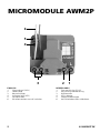
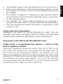
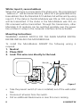
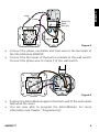
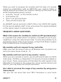
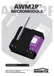
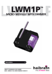
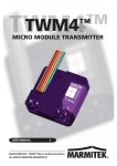
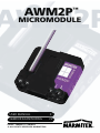
AWM2P™
AWM2P
MICROMODULE
USER MANUAL
3
GEBRUIKSAANWIJZING
73
20262 / 20080521 • AWM2P TM
© ALL RIGHTS RESERVED MARMITEK®
MICROMODULE AWM2P
6
5
4
3
ENGLISH
1.
Phase clamp (230V)
2.
Load clamp
3.
Neutral clamps
4.
Indicator light (LED)
5.
Set up button
6.
Wire connections to wall switches
2
2
1
NEDERLANDS
1.
Fase aansluiting (230V)
2.
Aansluiting voor belasting
3.
Nulklemmen
4.
LED indicator
5.
Programmeerknopje
6.
Aansluitdraden voor schakelaars
© MARMITEK
Marmitek X-10 transmitter for 2 addresses with a built-in
appliance module.
SAFETY WARNINGS
• The wiring of your electrical installation is live (230 V) and
extremely dangerous. Never connect the module when plugged
into the mains. Always turn off the main switch before starting
the installation.
• This product is for professional use and should be installed by a
certified installer.
• To prevent short circuits, this product should only be used inside and
only in dry spaces. Do not expose the components to rain or moisture.
Do not use the product close to a bath, swimming pool etc.
• Do not expose the components of your systems to extremely
high temperatures or bright light sources.
• In case of improper usage or if you have altered and repaired
the product yourself, all guarantees expire. Marmitek does
not accept responsibility in the case of improper usage of the
product or when the product is used for purposes other than
specified. Marmitek does not accept responsibility for additional
damage other than covered by the legal product responsibility.
• This product is not a toy. Keep out of reach of children.
• Do not open the product: the device may contain live parts.
The product should only be repaired or serviced by a qualified
repairman.
• Automatic switching devices provide comfort, but can also
be dangerous. They can surprise people or can ignite clothing
hanging over an electric heat source. Please be careful and take
appropriate measures to avoid accidents.
HOW DOES MARMITEK X-10 WORK?
Marmitek X-10 components use the existing mains wiring to
communicate (using Marmitek X-10 signals). You can build a
complete system using the three different kind of components of
the Marmitek X-10 System:
AWM2P™
3
ENGLISH
MARMITEK MICROMODULE AWM2P
1. Modules
These components will receive Marmitek X-10 signals and will switch
or dim the attached lamp or appliance.
2. Controllers
These components will transmit Marmitek X-10 signals and thus will
control the Modules.
3. Transmitters
Wireless components like remotes. The signals of these components
will be received by a controller with transceiver functionality (IRRF
7243, TM13, CM15Pro or console of a Marmitek SecuritySystem).
The Transceiver will translate the signals into Marmitek X-10 signals
on the power line.
ADRESSES
Up to a maximum of 256 different addresses can be preset. These are
subdivided into a so-called HouseCode (A to P incl.) and a UnitCode
(1 to 16 incl.). The HouseCode can also be set on the controllers, so
that the controllers and modules become part of the same system.
The address can be set either using code dials or by pressing buttons,
depending on the type of module.
The Marmitek X-10 System uses standard commands, which control
all units with the same HouseCode at the same time (e.g. all lights
on, all off, etc.).
SIGNAL RANGE
Range of Marmitek X-10 signals over the Power Line and how
to increase the range.
The Marmitek X-10 System is based on power line communication. The
range of the Marmitek X-10 signals very much depends on the local
circumstances. On average the range is a cable length of 80 meters.
If you have difficulties with the range of your Marmitek X-10
signals, please pay attention to the following facts:
1. When several phases are used in the house, it can be necessary
to couple these phases for Marmitek X-10 signals. You can
4
© MARMITEK
2. It is possible that Marmitek X-10 signals are attenuated by devices
and lights which are connected to the power line. In a normal home
situation this effect is negligible (the Marmitek X-10 system is using
active gain control to eliminate the effects). However, it is possible that
a particular device in your house is attenuating the signals so much
that the range of Marmitek X-10 signals is decreased significantly.
When you have range problems, it is wise to try to locate the device
which is attenuating the signals simply by unplugging devices from
the power line, and testing the differences in range for your Marmitek
system. When e.g. your conclusion is that e.g. your computer monitor
is attenuating the signal, you can use a FM10 Plug-in Filter between
the power line and the monitor to eliminate the effects.
Known devices which can cause attenuation are:
PC Monitors
PCs with heavy internal power supplies
Old Televisions
Copiers
Fluorescent Lights
Gas Discharge Lamps (Energy Saving Lamps)
3. Some (old) devices are able to disturb the signal by transmitting
noise on the power line. Because the Marmitek X-10 signals are
transmitted on 120 kHz, only noise on or near this frequency
will have influence on the range. When you use a FM10 Filter to
connect this device to the power line, the noise will be filtered.
4. The Marmitek X-10 protocol has several mechanism to avoid
modules to be switched on or off by other sources than your
Marmitek X-10 Controllers. However, it is possible that the
AWM2P™
5
ENGLISH
couple them with the use of a CAT 3000 active 3 phase coupler/
repeater (Art.No. 09304) and it is required if wall outlets and
lighting points are actually divided into several phases (several
groups is no problem for the Marmitek X-10 signal).
Marmitek X-10 signals are disturbed by e.g. baby phones which
are in TALK mode (continuous transmission). When these kind
of signals are present on the power line it is possible that the
Marmitek X-10 signals will not come through.
5. The mains do not stop at the front door of your home. Everything
that is attached to mains nearby your home can have influence on
Marmitek X-10 signals (e.g. heavy machinery). If you think that your
system is influenced by devices out of your house, it is advisable to
install FD10 Phase Coupler/Filter on each phase entering the house.
These filters will block signals coming into or going out of your
house, but will also match the impedance for the mains. Hereby
make your house Marmitek X-10 compatible for these units. To
couple the phases use a CAT 3000, see point 1 above.
INSTRUCTIONS FOR USE
APPLICATIONS/CHARACTERISTICS
• Because of its extremely small proportions the module can be
built in behind built in switches and wall outlets (minimal depth
flush switch with box 40mm, preferred: 50mm). The module is
also ideal for building in light armatures and for installing in small
spaces with for instance lowered ceilings.
• Multi-purpose: fully free choice, colour and model of switch
material.
• To this module two switches can be connected. One controls
the internal appliance module, but also controls the matching
X-10 command through the power line. With the second switch
ON/OFF commands can be sent for a second X-10 address.
• The address to be set up can be programmed through the power
line with every Marmitek X-10 remote control (e.g. Marmitek
EasyControl8™ remote control withTM13 transceiver).
• The AWM2P can react to one or more group commands (ALL
LIGHTS ON, ALL UNITS OFF). These functions are disabled by
default.
6
© MARMITEK
•
•
•
The AWM2P supports two way Marmitek X-10 communication.
Both normal switches (on-off) and Momentary switches can be
connected to the module. These are automatically recognized by
the AWM2P.
This module is suitable for installing two-way switches without
wiring between the switches (MicroModules pass on their status
to other MicroModules).
The AWM2P can control Macro’s/Scenario’s by operating a
conventional switch (with for instance Marmitek ActiveHomePro).
The internal appliance module remembers its status after a main
voltage cut-off.
Colour code wire connections
WARNING: THE WIRES OF THE MICROMODULE CARRY THE LIFE
DANGER 230V MAIN- VOLTAGE!! ALWAYS SWITCH OFF THE MAIN
MASTER SWITCH BEFORE INSTALLING THE MICROMODULE.
Description of the Marmitek MicroModule wires
Purple: Input 1, programmed base address + control of the
built-in appliance module
The built-in appliance module will switch from ON to OFF or vise
versa when the purple wire is connected with the phase wire. At
the same time the programmed address will transmit the new
status of the appliance module through the power line. Due to this
Marmitek X-10 transmission you are able to switch other Marmitek
X-10 modules (set to the same address). The new status will also
be recognized by other MicroModuls or e.g. the computer interface
(activating macro’s, status indication and more).
AWM2P™
7
ENGLISH
•
•
White: Input 2, second address
When the red wire is connected to the phase wire, the programmed
“address +1” will be transmitted (e.g. when A3 is programmed as the
base address then the Marmitek X-10 address A4 will be sent by using
input 2). If the status in the MicroModule was ON, an OFF command
will be transmitted. If the status in the MicroModule was OFF, an
ON command will be transmitted. Through this transmission, other
Marmitek X-10 modules can be switched remotely over the power
line or Macro’s setup in the computer interface can be activated.
Mounting Instructions
WARNING! ALWAYS SWITCH OFF THE MAIN MASTER SWITCH
BEFORE INSTALLING THE MICROMODULE.
To install the MicroModule AWM2P the following wiring is
required.
1. Neutral
2. Phase 230V
3. Load. This wire runs directly to the load.
Blue (N)
Brown
(L)
P
Black
•
Figure 1
•
•
Take the present switch (if one is installed) out of the wall outlet
box.
Disconnect all wires from the switch.
Pull an additional Neutral-wire in case this one is missing.
8
© MARMITEK
ENGLISH
PROG.
AWM2P
white
Purple
N
L
Brown (L)
Black
Blue (N)
P
Brown
(L)
Figure 2
•
•
Connect the phase, neutralize and load wire to the terminals of
the MicroModule AWM2P.
Connect the thin wires of the built-in module to the wall switch.
Connect the phase wire to clamp P of the wall switch.
P
PROG.
AWM2P
N
L
Figure 3
•
•
Position the MicroModule against the back wall of the wall outlet
behind all the wires.
You are now able to program the MicroModule. For more
information see chapter “Programming”.
AWM2P™
9
prog.
prog.
SAIX
SAIX
Figure 4
•
Install the wall switch at its original place after the MicroModule
is programmed.
Please note: due to heat generation, apply no more than one module
per flush socket / central socket!
Programming
WARNING: DO NOT FORGET TO TURN ON THE MAIN MASTER
SWITCH PRIOR TO PROGRAMMING.
Activate the setup mode.
The following steps have to be taken to start the setup procedure for
programming the MicroModule:
• Press the setup (prog.) button for at least 3 seconds (see figure
5). The LED should stay on after releasing the setup button.
• Warning! The MicroModule will leave the setup mode if it
doesn’t receive any commands within 60 seconds.
Exit setup mode
• Press the setup button once shortly; The red LED will turn off
now. You can also wait for at least 60 seconds so that the
MicroModule will exit the setup mode automatically.
10
© MARMITEK
ENGLISH
P
PROG.
AWM2P
N
L
PROG.
Figure 5
Activate or exit the setup mode.
Programming the X-10 address and the various options
The chart below shows the various possibilities to program the
MicroModule AWM2P
defaults
Programmable
Command
Light blinks
Address A1
Address A2 to P16
2x Address
2x
Doesn’t respond to
Responds to “All
2x “All lights on”
2x
“All Lights On”
Lights On”
Doesn’t respond to
Responds to “All
2x “All Units Off”
4x
“All Units Off”
Units Off”
For programming the Marmitek X-10 address and options you will be
able to use any Marmitek X-10 controller or remote control. For the
following explanation we used a Marmitek 8-in-1 remote control to
AWM2P™
11
program the preferred settings (When you use an RF remote control
like the Marmitek 8-in-1, then a TM13 Plug-in Transceiver is required
to convert the RF signals to the X-10 commands on the power line).
Example 1. Program the Marmitek X-10 address E4:
• Setup your remote control (see manual 8-in-1) and the TM13
transceiver to house code E.
• Start with the MicroModule in setup mode.
• Press the Marmitek X-10 button (marked with the symbol of a
house) of the 8-in-1 remote control and then press button 4.
• Press the “ON” button 2x (= channel+).
• The MicroModule responds by blinking the LED twice.
• The address E4 is programmed.
Example 2. Program the function “All Units Off”
• Make sure you program the required Marmitek X-10 address
first!! (e.g. E4).
• Leave the remote control and the TM13 Transceiver on
HouseCode E or set it to the right HouseCode.
• Start with the MicroModule in setup mode.
• Press button marked with “All Units Off” 2x (= mute).
• The MicroModule responds by blinking the LED 4x.
NOTES:
• When you program the MicroModule, always program the
address first followed by the optional functions.
• If the MicroModule receives a new address during setup mode,
the optional functions will be automatically reset to the factory
defaults.
• If you have programmed the address, but you wish to change it
again you need to switch the AWM2P out of the programming
mode and put it in the programming mode again.
• When programming the AWM2P, do not give the commands
with too little time in between, keep 1 second pauses in between
the commands.
12
© MARMITEK
An AWM2P cannot send ALL LIGHTS ON or ALL UNITS OFF signals
for the second address itself. It can only receive this signal and based
on this signal, adjust its internal status.
FREQENTLY ASKED QUESTIONS
What is the reason for modules to switch on/off spontaneously?
It is possible that a Marmitek X-10 System is installed at one of your
neighbours using the same House Code. To solve this problem try to
change the House Code of your system, or have FD10 Phase Coupler/
Filter installed at your incoming mains.
My modules will not respond to my controller.
Make sure that the House Code on all Modules and Controllers are
set to the same House Code (A .. P).
My modules will not react to my remote / sensor.
When you use a remote or sensor, you should have at least one TM13
Transceiver, CM15Pro or Marmitek X-10 Security Console installed in
your house. These components will translate the radio signals to the
Marmitek X-10 signal on the power line. Using several remotes and
sensors, you only need one central transceiver.
Am I able to increase the range of my remotes by using more
Transceivers?
Yes, you can use more than one TM13 Transceiver in your home
AWM2P™
13
ENGLISH
When you wish to program the module with the help of a remote
control in combination with an IRRF7243, you need to follow a
slightly different procedure (for instance: setting up UnitCode 2 with
an 8in1 Multimedia remote control):
• push the “house” on the remote control
• push button [2]
• give 2 x an [on] command
• close off with button [2]
when the range of your remotes is not sufficient. The TM13 is using
so called collision detection to prevent signals to be disturbed when
more than one TM13 is transmitting. TM13’s will wait for a quite
power line before transmitting their data. To prevent your Marmitek
X-10 System to become slow or to prevent dimming from becoming
less smooth, make sure that the TM13 units are placed as far away
from each other as possible.
Can I use more switches to control the AWM2P?
Yes, you can connect more switches to the first switch. However, they
all need to be normal switches (on-off) or all Momentary switches.
Do you still have questions?
Please check out www.marmitek.com for more information.
TECHNICAL DATA
Power:
Electricity consumption
Switching power:
230V ±10%, 50 Hz
< 30 mA capacitive
3600W 230V with temperature
and mounting restrictions.
2300W/230V 500W ind cap
Signal transmission:
> 5Vpp in 5 Ohm at 120 kHz
± 1kHz
X-10 transmission:
1 pulse burst on 0˚ and 180˚
Signal sensitivity:
25mVpp … 6 Vpp at 120 kHz
± 4kHz
Signal / interference proportion: 1,35 : 1
X-10 Key codes:
All units Off, All Lights On,
On, Off, Status Request.
Switch use:
normal switches (make/break)
or Momentary switches
Connection range:
Up to 2,5 mm2
Environment temperature:
-10°C to +35°C (operation)
-20°C to +70°C (storage)
Dimensions:
46x46x16mm.
14
© MARMITEK