1
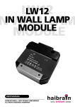
LWM1P
LWM1P
™
MICRO MODULE WITH DIMMER
USER MANUAL
3
LWM1P™ MICROMODULE WITH DIMMER
20259 / 20080521 © ALL RIGHTS RESERVED HAIBRAIN ®
MicroModule
LWM1P
6
5
4
3
ENGLISH
1.Phase clamp (230V)
2.Load clamp
3.Neutral clamps
4.Indicator light (LED)
5.Set up button
6.Wire connections to wall switch
2
2
1
NEDERLANDS
1.Fase aansluiting (230V)
2.Aansluiting voor belasting
3.Nullklemmen
4.LED indicator
5.Programmeerknopje
6.Aansluitdraden voor schakelaar
© HAIBRAIN
SAFETY WARNINGS
• The wiring of your electrical installation is live (230 V) and
extremely dangerous. Never connect the module when
plugged into the mains. Always turn off the main switch
before starting the installation.
• This product is for professional use and should be installed by
a certified installer.
• To prevent short circuits, this product should only be used
inside and only in dry spaces. Do not expose the components
to rain or moisture. Do not use the product close to a bath,
swimming pool etc.
• Do not expose the components of your systems to extremely
high temperatures or bright light sources.
• Do not open the product: the device contains live parts. The
product should only be repaired or serviced by a qualified
repairman.
• In case of improper usage or if you have opened, altered and
repaired the product yourself, all guarantees expire. Haibrain
does not accept responsibility in the case of improper usage of
the product or when the product is used for purposes other
than specified. Haibrain does not accept responsibility for
additional damage other than covered by the legal product
responsibility.
• This product is not a toy. Keep out of reach of children.
• Automatic switching devices provide comfort, but can also be
dangerous. They can surprise people or can ignite clothing
hanging over an electric heat source. Please be careful and
take appropriate measures to avoid accidents.
LWM1PTM
3
ENGLISH
LWM1P™
BUILT-IN DIMMER MODULE
TABLE OF CONTENTS
HOW DOES HAIBRAIN X-10 WORK?
ADRESSES
SIGNAL RANGE
INSTRUCTIONS FOR USE
INTRODUCTION
FUNCTIONS
MOUNTING INSTRUCTIONS
PROGRAMMING
USAGE OF THE MICROMODULES IN A 3 PHASE INSTALLATION
TESTING THE FUSE
LOW VOLTAGE HALOGEN LIGHTING
FREQENTLY ASKED QUESTIONS
TECHNICAL DATA
4
5
5
7
7
7
10
11
13
13
14
15
17
HOW DOES HAIBRAIN X-10 WORK?
Haibrain X-10 components use the existing mains wiring to
communicate (using Haibrain X-10 signals). You can build a
complete system using the three different kind of components of
the Haibrain X-10 System:
These components will receive Haibrain X-10
signals and will switch or dim the attached
lamp or appliance.
These components will transmit Haibrain X2. Controllers:
10 signals and thus will control the Modules.
3. Transmitters: Wireless components like remotes. The signals
of these components will be received by a
controller with transceiver functionality (IRRF
7243, TM13, CM15Pro or console of a
Haibrain Security System). The Transceiver will
translate the signals into Haibrain X-10 signals
on the power line.
1. Modules:
4
© HAIBRAIN
SIGNAL RANGE
Range of Haibrain X-10 signals over the Power Line and
how to increase the range.
The Haibrain X-10 System is based on power line
communication. The range of the Haibrain X-10 signals very
much depends on the local circumstances. On average the range
is a cable length of 80 meters.
If you have difficulties with the range of your Haibrain
X-10 signals, please pay attention to the following facts:
1. When several phases are used in the house, it can be necessary
to couple these phases for Haibrain X-10 signals. You can
couple them with the use of a CAT 3000 active 3 phase
coupler/repeater (Art.No. 09304) and it is required if wall
outlets and lighting points are actually divided into several
phases (several groups is no problem for the Haibrain X-10
signal).
2. It is possible that Haibrain X-10 signals are attenuated by
devices and lights which are connected to the power line. In a
normal home situation this effect is negligible (the Haibrain
X-10 system is using active gain control to eliminate the
effects). However, it is possible that a particular device in your
house is attenuating the signals so much that the range of
Haibrain X-10 signals is decreased significantly. When you
have range problems, it is wise to try to locate the device
which is attenuating the signals simply by unplugging devices
LWM1PTM
5
ENGLISH
ADRESSES
Up to a maximum of 256 different addresses can be preset. These
are subdivided into a so-called HouseCode (A to P incl.) and a
UnitCode (1 to 16 incl.). The HouseCode can also be set on the
controllers, so that the controllers and modules become part of
the same system. The address can be set either using code dials
or by pressing buttons, depending on the type of module.
The Haibrain X-10 System uses standard commands, which
control all units with the same HouseCode at the same time (e.g.
all lights on, all off, etc.).
from the power line, and testing the differences in range for
your Haibrain system. When e.g. your conclusion is that e.g.
your computer monitor is attenuating the signal, you can use a
FM10 Plug-in Filter between the power line and the monitor to
eliminate the effects.
Known devices which can cause attenuation are:
PC Monitors
PCs with heavy internal power supplies
Old Televisions
Copiers
Fluorescent Lights
Gas Discharge Lamps (Energy Saving Lamps)
3. Some (old) devices are able to disturb the signal by transmitting
noise on the power line. Because the Haibrain X-10 signals are
transmitted on 120 kHz, only noise on or near this frequency
will have influence on the range. When you use a FM10 Filter
to connect this device to the power line, the noise will be
filtered.
4. The Haibrain X-10 protocol has several mechanism to avoid
modules to be switched on or off by other sources than your
Haibrain X-10 Controllers. However, it is possible that the
Haibrain X-10 signals are disturbed by e.g. baby phones which
are in TALK mode (continuous transmission). When these kind
of signals are present on the power line it is possible that the
Haibrain X-10 signals will not come through.
5. The mains do not stop at the front door of your home.
Everything that is attached to mains nearby your home can
have influence on Haibrain X-10 signals (e.g. heavy machinery).
If you think that your system is influenced by devices out of
your house, it is advisable to install FD10 Phase Coupler/Filter
on each phase entering the house. These filters will block
signals coming into or going out of your house, but will also
match the impedance for the mains. The FD10’s will not only
filter but will also couple the phases (please see 1). To couple
the phases use a CAT 3000, see point 1 above.
6
© HAIBRAIN
INTRODUCTION
Congratulations on the purchase of the Haibrain X-10 built-in
dimmer module LWM1P.
• Because of its extremely small proportions, the module can be
built in behind wall switches and wall outlets (minimal
backbox depth 40mm, advice 50mm). The module is also
ideally suited to build in light armatures and for installation in
small spaces in for instance lowered ceilings.
• Multi-purpose: fully free choice in brand, colour and model
switch material. With the built-in dimmer you can switch and
dim 230V light bulbs, 230V halogen lighting and low voltage
halogen lighting with electronic transformer suitable for phaseingate up to 120 Watt.
• The module can be controlled by Momentary switches
connected to the module or at a distance, making use of the
Haibrain X-10 (plc) signal through the power line.
• In case of a voltage cut-off, the module will save the reading
prior to the cut-off. (dim level/off).
Please note: due to heat generation, apply no more than
one module per flush socket / central socket!
FUNCTIONS
• Local control via the switch attached to the module or remote
control using Haibrain X-10.
• Built-in dimmer, 120W.
• Two-way X-10: transmits the set dimmer level to other LWM1P,
LD11, LW12 and LW11 modules (set to the same HouseCode
and UnitCode).
• Softstart and softdim.
• Memory function for last dimmer setting.
• Responds to ON, OFF, DIM, BRIGHT and extended X-10
(dimmer setting originates from other LWM1P modules).
LWM1PTM
7
ENGLISH
INSTRUCTIONS FOR USE - LWM1P™
BUILT-IN DIMMER MODULE
• Can respond to All Lights On and All Units Off (configuration).
• Choice between 1-way momentary switch or 2-way
momentary switch.
Explanation about connecting switches:
Note: In the standard setting the LWM1P module assumes a
‘2-way momentary switch’ has been connected.
“1-way momentary switch”:
Push to make switch without intermediate setting. 1
short press is ON, keeping the button pressed is DIM,
second press is OFF. When connecting this type of
switch, the white and purple wires are connected to
the impulse contact of the switch. The phasewire (L)
is connected to the P or L contact of the switch.
Colour coding for the 1-way momentary switch:
Connect White and Purple: alternating ON/BRIGHTER and
OFF/DIM.
PROG.
LWM1P
White
Purple
N
L
Brown(L)
Black
Blue(N)
P
Brown
(L)
8
© HAIBRAIN
ENGLISH
“2-way momentary switch”
Push to make switch with intermediate setting. Both
the top and bottom part of the switch can be
pressed. Short press top is ON, long press top is
BRIGHTER. Short press bottom is OFF, long press
bottom is DIM.
When connecting this type of switch, the purple wire
is connected to the contact for the top part of the
switch (ON/BRIGHTER) and the white wire to the contact for the
bottom part of the switch (OFF/DIM).
The phase wire is connected to the common P or L contact of the
switch.
PROG.
LWM1P
White
Purple
N
L
Brown (L)
Black
Blue (N)
P
Brown
(L)
Colour coding for the 2-way momentary switch:
Purple: ON/BRIGHTER
White: OFF/DIM
LWM1PTM
9
MOUNTING INSTRUCTIONS
WARNING! ALWAYS SWITCH OFF THE MAIN MASTER SWITCH
BEFORE INSTALLING THE MICROMODULE.
To install the MicroModule LWM1P the following wiring is
required at the module installation point.
Phase 230V
Neutral
Load. This wire runs directly to the load.
•
•
•
•
•
•
•
•
Take the wall switch, if present, out of the wall outlet.
Disconnect all wires from the switch.
Pull an additional N-wire in case this one is missing.
Connect the phase, neutral and load wire to the terminals of
the MicroModule LWM1P.
Connect the thin wires of the built-in module and phase to the
wall switch. See “Explanation about connecting switches” for
more information.
Position the MicroModule against the back wall of the wall
outlet behind all the wires.
You are now able to program the MicroModule. For more
information see chapter “Programming”.
Install the wall switch at its original place after the
MicroModule is programmed.
10
© HAIBRAIN
Activate the setup procedure.
The following steps have to be taken to start the setup procedure
for programming the MicroModule:
• Press the setup (prog.) button for at least 3 seconds. The LED
should stay on after releasing the setup button.
• Warning! The MicroModule will leave the setup mode if it
doesn’t receive any commands within 60 seconds.
Exit setup mode
• Press the setup button once shortly. You can also wait for at
least 60 seconds so that the MicroModule will exit the setup
mode automatically.
P
PROG.
LWM1P
N
L
PROG.
Activate or exit the setup mode.
LWM1PTM
11
ENGLISH
PROGRAMMING
WARNING: DO NOT FORGET TO TURN ON THE MAIN MASTER
SWITCH PRIOR TO PROGRAMMING.
Programming the X10 address and the various options.
The chart below shows the various possibilities to program the
MicroModule LWM1P.
Factory defaults
Programmable
Command
Light blinks
Address A1
Address A2 .. P16
2x Address
2x
Doesn’t respond to
“All Lights On”
Responds to
“All lights On”
2x All Lights On
6x
Doesn’t respond to
“All Off”
Responds to
“All Off”
2x All Off
8x
Connected switch is a
2-way momentary switch
Connected switch is a
1-way momentary switch
2x Bright
12x
For programming the Haibrain X10 address and options you will
be able to use any Haibrain X10 controller or remote control,
apart from the CM11 computer interface.
For the following explanation we used a Haibrain 8-in-1 remote
control to program the preferred settings (when you use an RF
remote control like the Haibrain 8-in-1, then a TM13 Plug-in
Transceiver is required to convert the RF signals to the X10
commands through the power line).
Sample 1. Program the Haibrain X10 address E4:
• Setup your remote control (see manual 8-in-1) and the TM13
transceiver to house code E.
• Start with the MicroModule in setup mode.
• Press the Haibrain X10 button (marked with the symbol of a
house) of the 8-in-1 remote control and then press button 4.
• Press the “ON” button 2x (= channel+).
• The MicroModule responds by blinking the LED twice.
• The address E4 is programmed.
• If you wish to program more options, you have to make sure
the module remains in setup mode.
Sample 2. Program the function “All Units Off”.
• Make sure you program the required Haibrain X10 address
first!! (e.g. E4).
12
© HAIBRAIN
NOTES:
• When you program the MicroModule, always program the
address first the optional functions second.
• If the MicroModule receives a new address during setup mode,
the optional functions will be automatically reset to the default
settings.
USAGE OF THE MICROMODULES IN A 3 PHASE
INSTALLATION
The X10 transmitters of the MicroModules transmit the command
only once for use in the phase of which they are connected.
When you want to receive the commands on your other phases
as well, you will need to install the CAT3000 phase
coupler/repeater.
The FD10 phase coupling filters can be used as netfilters, but not
as phase couplers in combination with the LWM1P.
TESTING THE FUSE
Test the performance of the fuse (type TR5-1, 6 AT).
Disconnect the LWM1P from the load (lamp, transformer). Then
measure the voltage on the output clamp with a voltmeter. If
there is no voltage, the fuse is defective.
NOTE: In case of a melted fuse the programming LED still
blinks.
LWM1PTM
13
ENGLISH
• Make sure the module remains in setup mode.
• Press button marked with “All Off” 2x (= mute).
• The MicroModule responds by blinking the LED 8x.
Replacing the fuse after melt-through.
LWM1P
LWM1P
Replacing the fuse is possible without opening the module! (if
the module has been opened the guarantee no longer applies).
Remove the film above the fuse and then pull the fuse out of the
module with pointed pliers.
Replace the fuse with a fuse of one of the following types (with
the application of other types the guarantee no longer applies):
Supplier dimmer fuse
Description
Order number supplier
Littelfuse
LT-5 ALg
0663.01.6
Bussman
ETF Radial Lead Micro Fuse
BK ETF1.6
ELU
Sub miniature fuse links
166050-1,6AT
Wickmann
Subminiatur fuse No 372.TR5
372-1160-041
Bel fuse
Time Lag Radial Lead Micro Fuse
MTR1,6 short leads
NEVER CONNECT A WOUND VOLTAGE TRANSFORMER TO THE
LWM1P WHILE THE VOLTAGE IS SWITCHED ON. THE FUSE CAN
MELT AS A RESULT.
LOW VOLTAGE HALOGEN LIGHTING
The LWM1P can only be used in combination with the electronic
transformer suitable for leading-edge phase dimmers. The
LWM1P cannot be coupled to transformers suitable for trailingedge phase dimmers. Coupling it to such a transformer will cause
a humming sound and damage the LWM1P. The right to
guarantee will also expire as a result.
14
© HAIBRAIN
My modules will not respond to my controller.
Make sure that the House Code on all Modules and Controllers
are set to the same House Code (A .. P).
My modules will not react to my remote / sensor. When
you use a remote or sensor, you should have at least one TM13
Transceiver or Haibrain Security Console installed in your house.
These components will translate the radio signals to the Haibrain
X-10 signal on the power line. Only one Transceiver should be
installed for all remotes and sensors set to the same House Code.
Am I able to increase the range of my remotes by using
more Transceivers?
Yes, you can use more than one TM13 Transceiver in your home
when the range of your remotes is not sufficient. The TM13 is
using so called collision detection to prevent signals to be
disturbed when more than one TM13 is transmitting. TM13’s will
wait for a quite power line before transmitting their data. To
prevent your Haibrain X-10 System to become slow or to prevent
dimming from becoming less smooth, make sure that the TM13
units are placed as far away from each other as possible.
The module suddenly starts to blink for a short time.
Electronic dimmers, such as the LWM1P, make use of cutting in or
cutting off the sine in order to transform voltage. In an unstable
mains system, or as a consequence of short low frequency pulses,
the shape of the sine can be disrupted, resulting in light
variations. This phenomenon does not harm the modules.
LWM1PTM
15
ENGLISH
FREQUENTLY ASKED QUESTIONS
What is the reason for modules to switch on/off
spontaneously?
It is possible that a Haibrain X-10 System is installed at one of
your neighbours using the same House Code. To solve this
problem try to change the House Code of your system, or have
FD10 Phase Coupler/Filter installed at your incoming mains.
Programming the LWM1P through the IRRF7243 is not
working.
If you wish to program the module with the help of a remote
control and the IRRF7243 you need to follow a slightly different
procedure (Example: setting UnitCode 2 with an 8in1 Multimedia
remote control):
• push the “house” on the remote control.
• push button [2].
• give an [on] command 2 times.
• close off with button [2].
The last action is only necessary when using the IRRF7243. When
using a TM13 or an alarm central, the address will already be
altered with the second on- command.
Can I connect a two-way switch to the LWM1P?
No, you can only connect a Momentary switch to the LWM1P. For
two-way switches you can use the AWM2P although you cannot
dim with this one.
Can I use several switches to control the LWM1P?
Yes, you can connect more switches parallel to the first switch.
They do have to be all 1-way momentary switches or all 2-way
momentary switches.
My LWM1P is getting warm.
Because of the micromodules’ small size, they become warmer
than the ‘larger’ Haibrain Home Automation components.
However, this is nothing to worry about.
Do you still have questions? Please check out
http://www.haibrain.com.for more information.
16
© HAIBRAIN
X-10 Key codes:
X-10 transmisson:
Switch use:
Connection reach:
Fuse:
Environment temperature:
Dimensions:
Built-in depth:
230V ±10% - 50Hz.
<30 mA capacitive
120W/230V light bulbs.
100W Low voltage halogen lighting
with wound voltage transformer.
120W Low voltage halogen lighting
with electronic voltage transformer.
(recommended voltage transformer:
Osram HTM series. If you use other
voltage transformers, we advise you
to test the combination before
building in the system).
Softstart/Softdim.
Memory reading for dim level
All units Off, All Lights On, On, Off,
Dim, Bright, Extended Code 1 type
3, Pre-Set Dim, Status Request.
1 pulse on 0° and 180°.
1 or 2 way momentary switch.
Till 2.5 mm2
Radial lead micro fuse, 1.6AT, 250V.
-10°C to +35°C (operation)
-20°C to +70°C (storage).
46x46x16mm.
40 mm (minimum), 50 mm (advised)
Environmental Information for Customers in the European Union
European Directive 2002/96/EC requires that the equipment bearing this symbol
on the product and/or its packaging must not be disposed of with unsorted
municipal waste. The symbol indicates that this product should be disposed of
separately from regular household waste streams. It is your responsibility to dispose of this
and other electric and electronic equipment via designated collection facilities appointed by
the government or local authorities. Correct disposal and recycling will help prevent
potential negative consequences to the environment and human health. For more detailed
information about the disposal of your old equipment, please contact your local authorities,
waste disposal service, or the shop where you purchased the product.
LWM1PTM
17
ENGLISH
TECHNICAL DATA
Power:
Supply current:
Capacity: