1
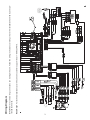
Installation Guide
®
ADVUV630
DEST
NAV
PWR-VOL
A/V
INPUT
What’s in the Box
Tools and Supplies
ADVUV630 Head Unit
External Microphone
Parking Brake Wire
Hardware Bag
Speaker Output Harness
Power Input Harness
2 x Accessory Harness
Installation Guide
You will need these tools and supplies to
install your ADVUV630:
•
Torx type, flat-head and Philips
screwdrivers
•
Wire cutters and strippers
•
Tools to remove existing radio (screw
driver, socket wrench set or other tools)
•
Electrical tape
•
Crimping tool
•
Volt meter/test light
•
Crimp connections
•
18 gauge wire for power connections
•
16 – 18 gauge speaker wire
WARNING! Never install this unit where operation and viewing could interfere with safe driving conditions.
1
Disconnecting the Battery
To prevent a short circuit, be sure to turn off the ignition and remove the negative (-) battery cable prior to installation.
NOTE: If the ADVUV630 is to be installed in a car equipped with an on-board drive or navigation computer, do
not disconnect the battery cable. If the cable is disconnected, the computer memory may be lost. Under these
conditions, use extra caution during installation to avoid causing a short circuit.
Replacing the Fuse
When replacing the fuse, use a new 15 Amp ATO replacement fuse. Using a fuse with an improper rating could
damage the unit and cause a fire.
ISO-DIN Installation
This unit is designed to fit into a 2.0 DIN dashboard opening, found in many imported cars. The unit has
threaded holes in the chassis side panels which may be used with the original factory mounting brackets of
some Toyota, Nissan, Mitsubishi, Isuzu, Hyundai and Honda vehicles to mount the radio to the dashboard.
Please consult with your local car stereo specialty shop for assistance on this type of installation.
1
2
Remove the existing factory radio from the dashboard or
center console mounting. Save all hardware and brackets
as they will be used to mount the new radio.
Remove the factory mounting brackets and hardware from
the existing radio and attach them to the new radio.
CAUTION: Do not exceed M5 X 6MM screw size. Longer
screws may damage components inside the chassis.
Place the radio in front of the dashboard opening so the
wiring can be brought through the mounting sleeve. Follow the wiring diagram carefully and make certain all connections are secure and insulated with wire nuts or electrical tape. After completing the wiring connections, plug the
ISO connectors into the mating sockets on the rear of the
chassis. Turn the unit on to confirm operation (vehicle ignition switch must be “on”). If the unit does not
operate, re-check all wiring until the problem is corrected.
Mount the new radio assembly to the dashboard or center console using the reverse procedure in step 1.
DEST
NAV
PWR-V
OL
3
4
A/V
INPU
T
CAUTION! Be careful not to damage the car wiring.
NOTE: It is the end-users responsibility to install and operate this unit in a manner in accordance with local,
state and federal laws. The PARKING BRAKE wire MUST BE CONNECTED as directed in the manual.
CAUTION: Do not block the cooling fan exit. If blocked, the unit may overheat and become damaged.
2
3
YELLOW
SAT Radio
GREEN
Cell Phone
Rear Right
Front Right
Front Left
Rear Left
Steering Wheel Control (SWC) requires PAC
SWI-PS Interface Adapter (Sold Separately)
SAT R
BLUE
Need Help? For technical assistance, call the Jensen customer support line at 1-800-323-4815.
Microphone
External Power Amplifier
Antenna
Auto antenna
control (connect
to antenna control
lead and power
supply of antenna
amplifier)
IMPORTANT: Incorrect wiring connections can damage the unit. Follow the wiring instructions carefully, or have the installation handled by an experienced technician.
Wiring Diagram
SAT L