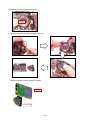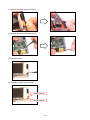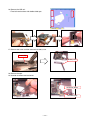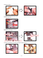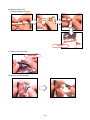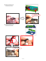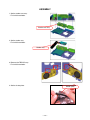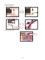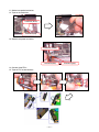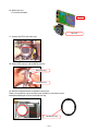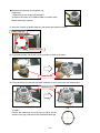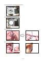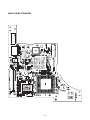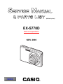
1
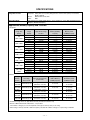
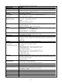
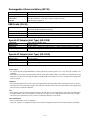
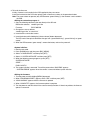
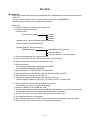
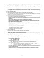
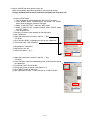
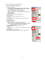
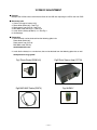
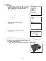
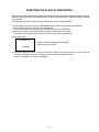
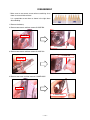
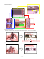
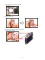
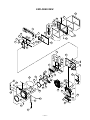
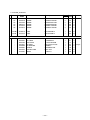
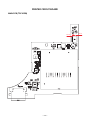
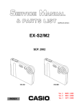
(without price)
EX-S770D
DivX correspondence
NOV. 2006
INDEX
R
CONTENTS
SPECIFICATIONS ....................................................................................................................................... 1
BLOCK DIAGRAM ...................................................................................................................................... 5
TEST MODE ................................................................................................................................................ 6
PROGRAM VERSION UPGRADING .......................................................................................................... 7
1. To update the firmware version ..................................................................................................... 7
2. How to restore the firmware ........................................................................................................... 8
3. To install the firmware .................................................................................................................... 9
ADJ TOOL ................................................................................................................................................. 10
1. Preparation ..................................................................................................................................... 10
2. How to use ADJ Tool when replacing Lens unit ........................................................................ 12
3. How to use ADJ Tool when replacing MAIN PCB ...................................................................... 13
VCOM DC ADJUSTMENT ........................................................................................................................ 14
CURRENT CONSUMPTION ..................................................................................................................... 17
THE COUNTERMEASURE FOR "SYSTEM ERROR" ............................................................................. 17
RESETTING THE PLACE OF DESTINATION .......................................................................................... 18
DISASSEMBLY ......................................................................................................................................... 19
ASSEMBLY ............................................................................................................................................... 28
EXPLODED VIEW ..................................................................................................................................... 37
PARTS LIST .............................................................................................................................................. 38
PRINTED CIRCUIT BOARDS ................................................................................................................... 40
SCHEMATIC DIAGRAMS ......................................................................................................................... 42
SPECIFICATIONS
Image Files Format
Snapshots: JPEG (Exif Ver.2.2); DCF (Design Rule for Camera File System) 1.0 standard;
Recording Media
Movies:
DPOF compliant
MPEG-4 AVI format, DivX
Audio:
WAV
Built-in Memory 6.0 MB, SDHC Memory Card, SD Memory Card, MMC (MultiMediaCard),
MMCplus (MultiMediaCardplus)
Approximate Memory Capacity and File sizes
• Snapshots
Image Size
(pixels)
7M
3072 x 2304
3:2
3072 x 2048
16:9
3072 x 1728
5M
2560 x 1920
3M
2048 x 1536
2M
1600 x 1200
VGA
640 x 480
(VGA)
Image
Quality
Approximate Image
File Size
Fine
Normal
Economy
Fine
Normal
Economy
Fine
Normal
Economy
Fine
Normal
Economy
Fine
Normal
Economy
Fine
Normal
Economy
Fine
Normal
Economy
4.32 MB
2.1 MB
1.44 MB
3.84 MB
2.0 MB
1.28 MB
3.24 MB
1.9 MB
1.08 MB
3.0 MB
1.8 MB
1.0 MB
1.92 MB
1.28 MB
640 KB
1.17 MB
780 KB
390 KB
360 KB
240 KB
120 KB
Approximate Built-in
Memory (6.0MB )
Capacity
1 image
2 images
3 images
1 image
2 images
4 images
1 image
2 images
5 images
1 image
3 images
5 images
2 images
4 images
8 images
4 images
7 images
12 images
15 images
22 images
40 images
Approximate SD
Memory Card*
(256MB) Capacity
55 images
110 images
158 images
61 images
116 images
176 images
73 images
121 images
206 images
78 images
128 images
221 images
121 images
180 images
348 images
196 images
286 images
530 images
625 images
937 images
1739 images
Approximate
Built-in Memory
(6.0MB) Capacity
Approximate
SD Memory Card*
(256MB) Capacity
8 minutes,
17 seconds
8 minutes,
17 seconds
15 minutes,
44 seconds
15 minutes,
44 seconds
43 minutes,
54 seconds
• Movies
Image
Quality
(Pixels)
HQ
640 x 480
HQ Wide
704 x 384
Normal
640 x 480
Normal Wide
704 x 384
LP
320 x 240
Maximum
Recording
Time Per File
Until memory full
Until memory full
Until memory full
Until memory full
Until memory full
Approximate Data Rate
(Frame Rate)
40 Megabits / second
(30 frames / second)
40 Megabits / second
(30 frames / second)
2.1 Megabits / second
(30 frames / second)
2.1 Megabits / second
(30 frames / second)
745 Kilobits / second
(15 frames / second)
8 seconds
8 seconds
15 seconds
15 seconds
42 seconds
* Number of image values are approximate and are provided for reference only.
* Based on Matsushita Electric Industrial Co., Ltd. products.
The number of images you can save depends on the type of memory card you are using.
* When using a memory card with a different capacity, calculate the number of images as a percentage of 256 MB.
—1—
Delete
Effective Pixels
Imaging Element
Lens/Focal Distance
Zoom
Focusing
Focus Modes
AF Area
Approximate Focus Range
(from lens surface)
Exposure Control
Shutter
Aperture Value
White Balance
Sensitivity
Self-timer
Built-in Flash
Flash Modes
Approximate Flash Range
Recording
Approximate Audio
Recording Times
Monitor Screen
Viewfinder
Timekeeping Functions
World Time
Input/Output Terminals
USB
Microphone
Speaker
1 file; all files (with memory protection feature)
7.2 million
1/2.5 square pixel primary color CCD (Total pixels: 7.41 million)
F2 .7 to 5.2/f=6.2 to 18.6 mm (Equivalent to 38 to 114 mm on a 35 mm film camera.)
Six lenses in five groups, including aspherical lens.
3X optical zoom / 4X digital zoom (Image Size: 7M (3072 x 2304 pixels)) (12X total zoom)
Contrast Detection Auto Focus
Auto Focus, Macro Focus, Pan Focus, Infinity Mode, Manual Focus
Spot or Multi; with AF assist lamp
Auto Focus
: 40cm to ∞ (1.3´ to ∞)
Macro Focus : 15cm to 50cm (5.9˝ to 19.7˝)
Infinity
:∞
Manual Focus : 15cm to ∞ (5.9˝ to ∞)
Range is affected by optical zoom.
Metering : Multi-pattern, center-weighted, and spot by imaging element
Exposure: Program AE
Exposure Compensation : –2EV to +2EV (1/3EV units)
CCD shutter; mechanical shutter
Snapshot (Auto)
: 1/2 to 1/2000 second
Snapshot (Night Scene) : 4 to 1/2000 second
Snapshot (Fireworks) : 2 seconds (fixed)
F2.7/4.3, auto switching
* Using optical zoom causes the aperture value to change.
Auto, fixed (6 modes), manual
Snapshots (Standard) : Auto, ISO 50, ISO 100, ISO 200, ISO 400
• Maximum sensitivity is ISO 800 when the BEST SHOT Anti Shake or High Sensitivity scene is
being used.
Movies : Auto
Trigger Times : 10 seconds, 2 seconds, Triple Self-timer
Auto, Off, On, Soft Flash, Red-eye reduction
Flash Range:
Wide Angle Optical Zoom : 0.15 to 3.9 meters (0.5´ to 12.8´)
Telephoto Optical Zoom : 0.4 to 2.0 meters (1.3´ to 6.6´)
• Flash Continuous Shutter
Wide Angle Optical Zoom : 0.26 to 1.68 meters (0.9´ to 5.5´)
Telephoto Optical Zoom : 0.4 to 0.87 meters (1.3´ to 2.9´)
* ISO Sensitivity: “Auto”
* Depends on zoom factor.
Snapshots (with audio); Macro; Self-timer; Continuous Shutter; BEST SHOT (scenes other than
Short Movie, Past Movie, and Voice Recording); movie with audio (Movie, Short Movie, Past
Movie); audio (Voice Recording)
* Audio is monaural.
Audio Snapshot : 30 seconds per image
After Recording : 30 seconds per image
Voice Recording : 18 minutes (when using built-in memory)
2.8-inch Wide TFT color LCD, 230,400 pixels (960 ✕ 240) pixels
Monitor screen
Built-in quartz digital clock
Date and Time : Recorded with image data, Time stamp
Auto Calendar : To 2049
162 cities in 32 time zones, City name, date, time, summer time
Cradle contact
USB 2.0 Hi-Speed compatible
Monaural
Monaural
—2—
Power Requirements
Power Requirements
Lithium ion rechargeable battery
(NP-20) x 1
Approximate Battery Life:
All of the values provided below represent the approximate amount of time under normal temperature (23°C ( 73° F)) before the
camera turns off. These values are not guaranteed. Low temperatures shorten battery life.
Number of Shots (CIPA)*1
Continuous Playback (Snapshot )*2
Continuous Movie Recording
Continuous Voice Recording*3
200 shots
290 minutes
90 minutes
400 minutes
• Battery: NP-20 (Rated Capacity: 700 mAh)
• Recording Medium: SD Memory Card
• Measurement Conditions
*1 Number of Shots (CIPA)
In accordance with CIPA standards
Normal temperature (23°C ( 73° F)), monitor on, zoom operation between full wide and full telephoto every 30 seconds, during
which two images are shot with flash; power turned off and back on every time 10 images are shot.
*2 Continuous Playback Time
Standard temperature (23°C ( 73° F)), one-image scroll approximately every 10 seconds
*3 Approximate continuous recording time
• The above values are based a new battery, starting from a full charge. Repeated charging shortens battery life.
• Frequency of flash, zoom, and Auto Focus usage, and the time the camera is on greatly affects recording time and number of
shots values.
Power Consumption
Dimensions
Weight
Bundled Accessories
3.7V DC Approximately 4.3W
94.5(W) ✕ 60.4(H) ✕ 17.3(D) mm
(3.7˝(W) ✕ 2.4˝(H) ✕ 0.7˝(D))
(Excluding projections; 13.7 mm (0.5˝) at thinnest part)
Approximately 127 g (4.5 oz) (excluding battery and bundled accessories)
Rechargeable Lithium Ion Battery (NP-20); USB Cradle (CA-34); Special AC Adaptor (AD-C52S
or AD-C52SG)/AC Power Cord; USB Cable; AV Cable; Strap; CD-ROM (2); Basic Reference
—3—
Rechargeable Lithium Ion Battery (NP-20)
Rated Voltage
3.7 V
Rated Capacitance
700 mAh
Operating Temperature
Dimensions
0 to 40°C (32 to 10 4°F)
33.0 (W) ✕ 50.0 (H) ✕ 4.7( D) mm (1.3˝(W) ✕ 2.0˝(H) ✕ 0.19˝(D))
Weight
Approximately 16 g (0.56 oz)
USB Cradle (CA-34)
Input/Output Terminals
Camera contact; USB port; external power supply terminal (DC IN 5.3 V);
Power Consumption
AV terminal (AV OUT: NTSC/PAL standards)
5.3V DC Approximately 3.2W
Dimensions
109(W) ✕ 24(H) ✕ 58(D) mm (4.3˝(W) ✕ 0.9˝(H) ✕ 2.3˝(D)) (Excluding projections)
Weight
Approximately 47 g (1.7 oz)
Special AC Adaptor (Inlet Type) (AD-C52S)
Input Power
100 to 240V AC, 50/60Hz, 90mA
Output Power
Dimensions
5.3V DC, 650mA
63(W) ✕ 20(H) ✕ 50(D) mm (2.5˝(W) ✕ 0.8˝(H) ✕ 2.0˝(D)) (excluding projections and cable)
Weight
Approximately 76 g (2.7 oz)
Special AC Adaptor (Inlet Type) (AD-C52G)
Input Power
100 to 240V AC, 50/60Hz, 90mA
Output Power
Dimensions
5.3V DC, 650mA
50(W) ✕ 20(H) ✕ 70(D) mm (2.0˝(W) ✕ 0.8˝(H) ✕ 2.8˝(D)) (excluding projections and cable)
Weight
Approximately 90 g (3.2 oz)
Power Supply
• Use only the special rechargeable lithium ion battery (NP-20) to power this camera. Use of any other type of battery is not
supported.
• The camera does not have a separate battery for the clock. The date and time settings of the camera are cleared about one day
after power is totally cut off (from both the battery and USB cradle). If this happens, be sure to reconfigure these settings after
power is restored.
LCD Panel
• The liq uid crystal panel of the monitor screen uses high-precision technology that provides a pixel yield in excess of 99 .99%.
This means that some pixels may not light or may remain lit at all times. This is due to the characteristics of the liquid crystal
panel, and does not indicate malfunction.
Lens
• Never apply too much force when cleaning the surface of the lens. Doing so can scratch the lens surface and cause malfunction.
• You may sometimes notice some distortion in certain types of images, such as a slight bend in lines that should be straight.
This is due to the characteristics of lens, and does not indicate malfunction of the camera.
Special AC Adaptor
• Power cord precautions for use in Singapore
The power cord set is not supplied. The power cord used must comply with relevant national and/or international standards.
—4—
CCD
Flexible-board
Moter
Flexible-Board
—5—
Connector
27PIN
VEE7.5
MOTER-dr
LV8054LP
CDS+Vdr
R2J45002HBG
Vcc3.3-1
MOTOR-BUS
CCD-BUS
VEE7.5C
VCC13C VEE7.5C
VCC13C
VCC13C VEE7.5C
VCC13
Connector
25PIN
Vcc5-2 Vcc3.3D
SD Card
Connector
SDBUS
Vcc3.3D
48MHz
LSI-SIP
R8J30215EBGV
(SATURN)
Vcc1.2 Vcc1.8 Vcc3.3D Vcc3.3A
LCDBUS
Connector
44PIN
AV-BUS
AV-BUS
Vcc3.3D
BS
MENU
DISP
WIDE
Vcc3.3A
VOUT
MONOOUT
POWER-BLOCK
FU100
FU101
DGND
DC
A/V
JACK
CRADLE
D+/D–
Connector
Connector
30PIN
CHARGE
DC
JACK
GND1
BAT+
MIC
Vcc1-0 Vcc3.3D
Dynamic
Speaker
–
VEE7.5
Backup
Capacitor
PWC TL0~5
8bit-Micom
UPD78F8011
EVcc3.3
LSI-SIP
Connector
10PIN
Strobe
+
VCC13
Vcc5-2
Vcc3.3-1
Vcc3.3A
Vcc3.3D
EVcc3.3
Vcc5-1
Vcc1.8
Vcc1-0
Vcc1-1
Vcc1.2
same as Kx810
8bit-BUS
VIDEO_IC
NJW1351KK1
Vcc1-1
Connector
17PIN
DOWN
EVcc3.3
RIGHT
SET
UP
DATE
REC
PLAY
LEFT
SHUTTER
POWER
TELE
32.769KHz
Vcc3.3A
MOVIE
KEY Flexible-board
AUDIO-IC
AK4633VG
AF_LED
R-LED
G-LED
KEY-BUS
CCD
Lenz-Unit
Vcc3.3D
2.8"-WIDE LCD
7-LED BL
LCD/BL
BLOCK DIAGRAM
BATTERY
TH
TEST MODE
Note: Never perform the menu items unless otherwise instructed. Doing so may cause destruction of
the data inside, which will make the camera unusable.
■ To boot the test mode
1. While firmly pressing down both [BS], [PW ON] and [UPPER], turn the power on.
[UPPER] button
[BS] button
2. After the version appears, press buttons in the order of [DOWN], [DOWN], [BS] and [MENU] in 0.5
second. The diagnostic menu appears.
[DOWN] button
[MENU] button
++ KX837f ++
Ve r 1 . 0 0
[BS] button
"DOWN" button -> "DOWN" button -> "BS" button -> "MENU" button
1
2
3
4
5
:VERSION INFO
:USB TCC TEST
: R O M U P D AT E
: L A S T M E M O RY
: F O R M AT
"SET" button
"MENU" button
—6—
1
2
3
4
:USB
:USB
:USB
:USB
TCC ON
TCC OFF
STORAGE
SPEED
PROGRAM VERSION UPGRADING
1. To update the firmware version
1. Prepare the memory card which contains the firmware for EX-S770D in the root directory.
EX-S770D.BIN
2. Insert the above memory card into the camera, and set a fully charged battery in the camera.
3. Press the [power button] while holding [MENU] depressed. Keep holding [MENU] depressed until
“PROGRAM UPDATE” appears in the display.
• The following appears.
• The version of the firmware in the memory card appears at the bottom of the display.
PROGRAM UPDATE
YES
NO
NEW VERSION IS
VER 1.00
NOTE 1) When a wrong software is mistakenly used,
the message below appears. Update the
firmware again with the correct software.
FILE ERROR!
(As of November 2006)
NOTE 2) When only the version appears in the display
even though you are trying to operate the
camera, charge the battery to the fullest and
try again. The level of the battery indicator
should be highest in order to update the
firmware.
4. Align the white cursor to [YES] by [UPPER] and [DOWN], and then press [SET].
• “NOW LOADING” appears in the display and the update starts.
5. “COMPLETE” appears after the update finishes.
6. Remove the memory card after turning the power off once. Turn the power back on again while holding
[MENU] depressed, and check the version.
• “VER.1.00” appears.
VER 1.00
(As of November 2006)
7. If the version is correct, turn the power off.
8. Finally, check the operation by recording, playing back and deleting an image.
—7—
2. How to restore the firmware
1. Prepare the firmware restoration program and change its name as follows;
rom837f-gm11.lbn 씮 saturn.bin
NOTE: This software and procedure automatically restores the firmware even if the firmware belongs
to a wrong model code. Make sure to use the correct software for the correct model.
2. Copy the above file to the root directory in the memory card.
3. Insert the memory card into the camera.
4. Set a fully charged battery in the camera.
NOTE: This software and procedure automatically restores the firmware even if the battery capacity of
the camera is low. Make sure to use a fully charged battery to prevent the danger of power
down during firmware restoration.
5. Turn the power on while pressing the [shutter release] button.
If the power does not turn on only by pressing the power button, insert the battery while holding the
[shutter release] button depressed.
• The LED next to the optical viewfinder changes from “green/red blinking”, “green blinking” to “green
steady”.
NOTE: This software and procedure automatically restores the firmware even if the firmware belongs
to a wrong model code. Make sure to use the correct software for the correct mode.
6. When the LED becomes “green steady”, the firmware restoration is finished.
Remove the battery and the memory card, and then turn the power off.
7. Turn the power on again while holding [BS] and [UPPER] depressed.
Check the model name and the program version (PR:) in the opening screen of the test menu.
++KX837f++
Ver 1.00
8. If the model name and the program version are correct, perform SYSTEM INITIAL to initialize the
system area.
“BS + UPPER + PW ON” 씮 “DOWN, DOWN, BS, MENU” 씮 “3:ROM UPDATE” 씮 “5:SYSTEM INITIAL”
NOTE: After SYSTEM INITIAL is performed, “SYSTEM ERROR” appears when the power is turned
on again.
9. Write the latest firmware. (Refer to page 6)
After the firmware is written, check the model name and the program version (PR:) in the opening
screen of the test menu.
10. Finally, start the camera normally to check the operation by recording, playing back and deleting an
image. Check also that the colors in the images are not too bright or two dark.
—8—
3. To install the firmware
Initially, firmware is not installed in the PCB supplied by the parts center.
Install the firmware into the PCB after replacing with a new one as shown in the procedures below.
Note: The camera does not operate (only LED becomes “green blinking”) if the firmware is not installed in
the PCB.
<Writing the restoration program 1>
1. Copy the following software to the root directly of the SD card.
Restoration software: rom837f-gm11.lbn
Firmware:
EX-S770D.BIN
2. Change the name as follows;
“rom837f-gm11.lbn” to “saturn.bin”
3. Insert the SD card into the camera.
4. Insert the battery while holding the [shutter release] button depressed.
The LED next to the optical viewfinder changes from “green/red blinking”, “green blinking” to “green
steady”.
5. When the LED becomes “green steady”, remove the battery and turn the power off.
<System Initialize>
1. Boot the test mode.
2. Press [DOWN] twice and then press [BS], [MENU].
3. Select “3: ROM UPDATE” and then press [SET].
4. Select “5: SYSTEM INITIALIZE” and then press [SET].
5. When the following message appears, press [SET].
SYSTEM INITIALIZE
START….
PUSH OK KEY?
6. The system initialize is executed. Turn off the power when “SUCCESS” appears.
* “SYSTEM ERROR” appears when the camera is turned off without system initialize.
<Writing the firmware>
1. Turn the power on while holding [MENU] depressed.
2. When “PROGRAM UPDATE” appears, select “YES” and then press [SET].
3. “NOW LOADING” appears while the firmware is updated.
4. When “COMPLETE” appears, the firmware update is complete.
5. Turn the power on and off to check if the camera normally functions. If there is no problem, the firmware
update is successful.
—9—
ADJ TOOL
■ Introduction
Make sure to perform the adjustment by the USB ADJ Tool “adj03SSAW.exe” when replacing the lens unit
or the PCB.
Here the necessary software, driver and setting are explained to use “adj03SSAW.exe”.
Note that the tool, drivers etc. are available only for Windows.
1. Preparation
1-1. Prepare the necessary software, driver and DLL file.
1) Prepare the following three files.
• Testmode driver
[testmode_driver] folder
uusbd.dll
uusbd.inf
uusbd.sys
* testmode_driver_2.0] is for Windows except Windows98.
* [testmode_driver] is for Windows98 only.
• ADJ tool, USB DLL and ADJ setting file
[adj03SSAW] folder
adj03SSAW.exe (ADJ tool itself)
uusbd.dll (USB DLL)
* .adt (ADJ setting file. Sorted by models)
2) Place the testmode driver in an appropriate place.
3) Place all of ADJ tool, USB DLL and ADJ setting file in the same folder.
1-2. Set the camera so that it recognizes the USB test mode.
1) Enter the test menu.
Turn the power on while pressing both [BS] and [UPPER].
Press [DOWN], [DOWN], [BS] and [MENU].
2) Move the cursor to “2: USB TCC TEST” and press [SET].
3) Move the cursor to “1: USB TCC ON” and press [RIGHT], [RIGHT] and [SET].
4) USB TCC ON is now active. Turn the power off.
5) The test menu appears first when the camera power is turned on.
* When changing the USB TCC ON to OFF, set “2: USB TCC OFF” in the test menu.
1-3. Install the USB driver for the USB test mode in the computer.
(The following is an example using the Windows Me.)
1) Prepare the USB driver for the USB test mode.
2) Turn the camera power on which is set in the USB test mode as shown in 1-2 and let it enter the USB
test mode directly (the test menu appears right after the power is turned on).
3) Connect the camera in the above status to the computer by the USB cable.
4) The “Add new hardware” wizard appears.
5) Check “Designate the place for the driver (for users with sufficient knowledge)” and press “Next”.
6) Check “Search for the optimum driver for the device (recommended)”.
— 10 —
7) Check “Designate the place to search”, designate the place which contains “inf” file in the driver by
pressing “Reference” button, and then press “Next” button.
8) When “Universal USB Driver (VMEM manufacturer’s name)” appears upon message “Searching for
the driver file for the following devices”, press “Next” button.
9) The file copy starts.
(If a message “uusbd.inf cannot be found” appears during the file copy, designate the same place as
in the step 7).
10) Press “Complete” button.
11) Right-click “My computer”, select “property”, and then open “Device manager”.
If “Universal USB Driver (VMEM manufacturer’s name)”,“USB device for UUSBD” can be found, the
computer has successfully recognized the driver.
12) Installing the test driver into either one enables the other one to recognize it.
* How to uninstall the USB driver for the USB test mode
• Connect the camera to the computer while in the USB test mode so that the computer recognizes
the camera.
• Right-click “My computer”, select “Property” and open “Device manager”.
• Select “USB device for UUSBD” , and then “Universal USB Driver (VMEM manufacturer's name)”.
• Press “Delete” button to delete the driver.
• When using Windows98/98SE/Me, delete the following three files;
(NOTE! Do NOT delete “usbd.inf” and “usbd.sys”, whose names are much alike the following.)
C:windows / inf / uusbd.inf
C:windows / inf / other / KashiwanoUUSBD.inf
C:windows / system32 / drivers / uusbd.sys
• The driver has been successfully deleted.
1-4. Use the USB ADJ Tool
1) Prepare ADJ tool, USB DLL and ADJ setting file in the same folder.
2) Turn the camera power on which is set in the USB test mode and let it enter the USB test mode directly
(the test menu appears right after the power is turned on).
3) Boot “adj03SSAW.exe” and use it as follows;
• To read ADJ data from the camera
앶앸 Press “READ ($9)”.
There is no neto set the model by “FW Item Set”.
• To write ADJ data into the camera
앶앸 Press “WRITE ($8)”.
• To save ADJ data which is read
앶앸 Select “File” and “Save All ADJ”, and save it under an appropriate name.
• Open ADJ data which is saved
앶앸 1. Select the model by "FW Item Set", and then press "Load FW ->" button.
2. Select “File” and “Open”, and open the necessary file.
• Language” radio button can switch the language between Japanese and English in which the name
of the ADJ ITEM is displayed.
• “Radix” radio button can switch the data display between decimal and hexadecimal notations.
— 11 —
2. How to use ADJ Tool when replacing Lens unit
Make sure to perform the following procedure after replacing the lens.
A floppy disk with the lens data is bundled in the spare parts of the lens unit.
1 Enter the TEST mode.
1. Turn the power on while pressing both "BS" and "UP" buttons.
2. Press "DOWN" button, "DOWN" button, "BS" button, and "MENU"
button while the program version is displayed.
3. Select "2.USB TCC TEST", and press "SET" button.
4. Select "1. USB TCC ON", and press "RIGHT" button, "RIGHT" button
and "SET" button.
5. Turn the power OFF.
2 Connect the camera to the computer by the USB cable.
3 Boot "adj03ssaw" .
4 Select the model name and click "Load FW " Key.
• EX-S770
5 Click "ADJ ALL READ", and display the data on the "adj03ssaw".
6 Find the No.1163, "LCD VCOM DC".
6
7 Write down this value(data).
8 Replace the Lens unit.
9 Perform the above 1 to 3.
4
0 Select the model name and click "Load FW " Key.
• EX-S770
A From "File/Open", open the bundled floppy disk, and transfer the data to
the "adj03ssaw".
A
B Find the No.1163,"LCD VCOM DC"
C Change the data to the former value.(Refer to 7).
D Click "WRITE" button of "ADJ ALL".
E After adjustment, change "1. USB TCC ON" to "2. USB TCC OFF".
D
— 12 —
3. How to use ADJ Tool when replacing MAIN PCB
Firmware is not installed in spare parts.
1 Enter the TEST mode.
1. Turn the power on while pressing both "BS" and "UP" buttons.
2. Press "DOWN" button, "DOWN" button, "BS" button and "MENU"
button while the program version is displayed.
3. Select "2.USB TCC TEST", and press "SET" button.
4. Select "1. USB TCC ON", and press "RIGHT" button, "RIGHT" button
and "SET" button.
5. Turn the power OFF.
2 Connect the camera to the PC by the USB cable.
3 Boot "adj03ssaw".
4 Select the model name and click "Load FW " Key.
• EX-S770
5 Click "ADJ ALL READ", and display the data on the "adj03ssaw".
6 Save the data.
7 Replace the MAIN PCB.
8 Writing the Firmware.
Write the firmware into a spare part after replacing one.
NOTE: If a battery is inserted without the firmware, only LED
blinks green and the camera does not operate.
9 Perform the above 1 to 3.
0 Select the model name and click "Load FW " Key.
• EX-S770
A Open the file which is saved above, and display the data on the
"adj03ssaw".
B Click "WRITE" button of "ADJ ALL".
C After adjustment, change "1. USB TCC ON" to "2. USB TCC OFF".
6
5
4
A
B
— 13 —
VCOM DC ADJUSTMENT
■ Purpose
Readjust the VCOM value to minimize the flicker of the LCD after replacing the LCD or the main PCB.
■ Necessary tools
1. Camera (Charge its battery fully)
2. Photo diode (S2281-01) : See Fig 1.
3. Photo sensor amp (C2719) : See Fig 2.
4. BNC-BNC cable (E2573) x 2 : See Fig 3.
5. 9-volt alkaline battery (6LR61Y) x 2 : See Fig 4.
6. Oscilloscope
■ Preparation
1. The three tools can be obtained from the following global site.
Photo diode (S2281-01)
Photo sensor amp (C2719)
BNC-BNC cable (E2573)
www.hamamatsu.com/
2. 9-volt alkaline battery is a standard one, but can be obtained from the following global site as well.
www.panasonic.co.jp/global/
Fig1 Photo Diode (S2281-01)
Fig2 Photo Sensor Amp (C2719)
Fig3 BNC-BNC Cable (E2573)
Fig4 6LR61Y
— 14 —
■ Procedure
1. Camera setting
a) Turn the power on while pressing “BS” and “UPPER”.
After pressing “DOWN” key twice, press “BS” and “MENU”.
Select "2:USB TCC TEST", and press "SET" button.
Select "1:USB TCC ON", and press "RIGHT" button ,"RIGHT"
button and "SET" button.
Figure (a) appears.
Figure (a)
1: VERSION INFO
2: USB TCC TEST
3: ROM UPDATE
4: LAST MEMORY
5: FORMAT
6: HARD TEST
7: IMAGE TEST
8: ADJ TEST
9: TEST SCRIPT
b) Select “8 : ADJ_TEST” and then press SET.
(See Figure (b).)
Figure (b)
c) Next, select “2. LCD” and then press SET.
(See Figure (c).)
Figure (c)
d) Pressing SET causes the right figure to appear.
(See Figure (d).)
Figure (d)
1: ADJ STAT CLR
2: LCD
3: LENS
.
.
.
1:VCOM
.
.
.
OK
O K - > R e g i s t e rW ri t e
VCOM = 0xca
This value is an example and differs by products
2. Connecting the TOOL
a) Place two 9-volt alkaline batteries in C2719.
b) Connect the output terminal of C2719 to the channel terminal of the oscilloscope by the BNC-BNCcable.
c) Connect the input terminal to the Photo Diode by the BNC cable.
d) Turn the oscilloscope and C2719 on.
* Pull the ON/OFF switch of C2719 this way and raise/lower it. (See below Figure.)
— 15 —
3. Measurement
a) Connect S2281-01 to the camera’s LCD monitor (see below).
AC Waveforms appear on the monitor screen of the oscilloscope.
* Change the Rf range of C2719 in case the range does not match.
Photo diode
S2281-01
INPUT
OUTPUT
Oscilloscope
Photo sensor amp
CAMERA
BNC-BNC cable
LCD
Minimize the
ripple components
b) After AC waveforms of the oscilloscope appear, minimize it by pressing the camera’s up/down buttons
(see the picture).
Make sure to visually check if it has been minimized.
[UPPER] button
[DOWN] button
After it has been minimized, press SET key.
The screen in the right figure appears and the new VCOM is
written (VCOM adjustment is finished.).
OK -> Register Write
VCOM = 0xca
ADJ DATA SET!
This value is only an example, and differs by products.
Return to the previous display by pressing MENU or PW key.
— 16 —
CURRENT CONSUMPTION
(1) Current consumption (DC in = 3.80 ± 0.1 [V])
• Make sure that current consumption is less than 215 mA in PLAY mode.
(TCC ON, USB connection : less than 250 mA)
• Make sure that current consumption is less than 440 mA in REC mode.
(TCC ON, USB connection : less than 475 mA)
• Make sure that current consumption is less than 500 µA when power is turned OFF.
(TCC ON, USB connection : less than 630 µA)
(2) The battery indicator changes according to the voltages as follows.
(PLAY mode)
• DC in = less than 3.71 ± 0.02 V:
• DC in = less than 3.62 ± 0.02 V:
(PLAY mode)
• DC in = less than 3.53 ± 0.02 V:
(PLAY mode)
THE COUNTERMEASURE FOR "SYSTEM ERROR"
System error may occur when the battery is removed while data is written to the internal memory.
■ PROCEDURE
1. Initialize the system.
a) Enter the TEST mode.
b) Select "3:ROM UPDATE" and press SET button.
c) Next, select "5:SYSTEM INITIAL" and press SET button.
d) The following message appears.
SYSTEM INITIALIZE
START ...
PUSH OK KEY?
e) Press SET button and System is initialized.
"SUCCESS !" appears on the monitor.
2. Write firmware.
Refer to the "1. To update the firmware version" on page 7.
Write the firmware.
If the TEST mode boots automatically, change "USB TCC ON" to "USB TCC OFF".
Replace the Main PCB if the camera does not recover.
— 17 —
RESETTING THE PLACE OF DESTINATION
When the main PCB is replaced, the setting of the destination will be changed, therefore resetting is required.
However, when the firmware is changed or fixed, the setting of the destination will be held, therefore resetting
is not required.
Use the destination setting script to change the destination flag as instructed below.
1. Have an SD card ready that have a corresponding script (autorun.scp) under the root directory.
2. Insert the SD card in the camera and turn on the power.
The script is located at Qv/soft/Adj_soft/exs770/Script in the service CD-ROM.
3. After a few seconds, one of the following messages will be shown in the screen.
The system will change the destination flag and turn off the camera automatically.
For Europe and UK
For Europe_UK
• Number of menu languages: 10 languages
• Movie filming time limited
Complete
4. Remove the SD card from the camera and turn on the power to confirm if the camera is set as you wish
including the number of the menu languages and the scene of the best shot mode.
If there is no problem, the setting is completed.
— 18 —
DISASSEMBLY
* Make sure to use correct screws when assembling since
there are several kinds of them.
It is a good idea to sort them as shown in the right when
disassembling.
1. Remove the battery.
2. Remove two screws and then remove C-CASE-BA.
Screws (S1)
C-CASE-BA
3. Remove two screws and then remove C-CASE-CA.
C-CASE-CA
Screws (S1)
4. Remove one screw and then remove C-CASE-ASSY.
Screw (S3)
C-CASE-ASSY
— 19 —
5. Remove six screws.
Screw (S3)
Screws (S4)
Screw (S4)
Screws (S2)
6. Remove the rear panel.
Attention: The power button and the shutter button come off together. Be sure not to lose them.
Rear panel
Power button
7. Remove the front panel.
Front panel
— 20 —
Shutter button
* Cam ring is fixed with three special screws ( ).
8. Remove the strap board.
Strap board
9. Remove the REC SUB ASSY and the DATA SUB ASSY.
* Fixed with double-sided tape.
REC SUB ASSY
DATA SUB ASSY
— 21 —
10. Release the lock and remove two FPCs.
FPCs
11. Remove two hooks and then remove the lens unit.
* Hooks are located at three locations as below.
Hooks
Lens unit
— 22 —
12. Remove the tape fixing the FPC(LCD).
13. Release the lock and remove one FPC.
14. Remove the tape.
15. Unsolder to remove two lead wires.
Lead wire (white)
Lead wire (black)
— 23 —
16. Remove the LCD unit.
* Fixed at three locations with double-sided tape.
17. Remove one screw and then remove the battery case.
Screw (S4)
Battery case
18. Remove the tape.
19. Unsolder to remove two lead wires.
Lead wire (black)
Lead wire (red)
— 24 —
20. Remove the tape.
21. Release the lock and remove two FPCs.
22. Remove one screw.
Screw (S5)
23. Unsolder to remove three lead wires.
24. Remove the main PCB.
Lead wire (yellow)
main PCB
Lead wire (blue)
Lead wire (gray)
25. Remove the protection tape and then discharge the strobe condenser.
— 25 —
26. Remove the key FPC.
* Fixed with double-sided tape.
Key FPC
27. Remove the shutter plate.
Shutter plate
28. Remove the TRIPOD ASSY.
— 26 —
29. Remove the strobe assy.
* Fixed with four hooks.
Strobe assy
30. Remove the strobe assy.
* Fixed with three hooks.
1
2
Strobe case assy
— 27 —
ASSEMBLY
1. Set the strobe case assy.
* Fix it with three hooks.
Strobe case assy
2. Set the strobe assy.
* Fix it with three hooks.
Strobe assy
3. Remove the TRIPOD assy.
* Fix it with three hooks.
4. Set the shutter plate.
Shutter plate
— 28 —
5. Set the LCD.
* Fix it with a double-sided tape at three locations.
Double-sided tape
* If the key FPC is not removed, place the LCD FPC under the key FPC.
6. Set the key FPC.
There are eight pins as your positioning guide.
Follow the assembling order as below.
— 29 —
7. Solder two LCD lead wires.
8. Tape on the lead wires.
Lead wire (white)
Lead wire (black)
9. Set the battery case with one screw.
Buttery case
10. Set the LCD with one screw.
Points
— 30 —
11. Solder two speaker lead wires.
12. Tape on the lead wires.
Lead wire (black)
Lead wire (red)
13. Solder three power lead wires.
Lead wire (yellow)
Lead wire (blue)
14. Connect three FPCs.
15. Tape on FPC at two locations.
— 31 —
Lead wire (gray)
16. Set the lens unit.
* Fix it with three hooks.
Hooks
Lens unit
17. Connect two FPCs of the lens unit.
18. Set the REC sub assy and the DATA sub assy.
REC sub assy
DATAsub assy
19. Stick the conductive (black) ring onto the front panel.
There is no conductive ring on the front panel assembly in maintenance parts.
Use double-sided tape to attach the conductive ring.
Conductive ring
— 32 —
■ Procedure for attaching the conductive ring
Preparation:
• Defective lens with the lens fully extended
(A defective lens from an EX-Z500 or Z600 can also be used.)
• Double-sided tape (4 pieces)
(1) Attach the 4 pieces of double-sided tape and remove the protective stickers.
Double-sided tape
Double-sided tape
(2) Fit the defective lens into the front panel assembly as shown in the figure.
Defective lens
(3) Fit the conductive ring onto the front panel assembly so that it passes over the defective lens.
Conductive ring
Top
<Caution>
Position the conductive ring so that the 4 slightly thicker
sections of the ring make contact with the double-sided tape.
— 33 —
(4) Take the front panel assembly off the defective lens.
(5) Press on the conductive ring to fix it in place.
20. Set the front panel.
21. Set the strap board.
Strap board
— 34 —
22. Set the power button the shutter button.
23. Set the rear panel.
24. Assemble with six screws.
screw (S3)
screws (S4)
screws (S2)
— 35 —
screw (S4)
25. Set the C-CASE-ASSY with one screw.
Screw (S3)
C-CASE-ASSY
26. Set the C-CASE-BA with two screws.
Screws (S1)
C-CASE-BA
27. Set the C-CASE-CA with two screws.
C-CASE-CA
Screws (S1)
— 36 —
EXPLODED VIEW
37
S3
S1
38
39
40
1
5
21
9
2
4
3
S4
41
6
S2
7
21
9
42
8
10
14
12
16
15
11
17
20
13
16
43
33
19
44
36
18
S5
28
29
S3
22
S6
23
44
S4
27
24
21
26
S1
S4
S1
34
32
35
45
S2
S1
— 37 —
31
30
25
PARTS LIST
1 EX-S770D_SILVER-EU
N
Item
Parts
Code
N
1
2
3
4
5
6
7
8
9
10
11
12
13
14
15
16
17
18
19
20
21
22
23
24
25
26
27
28
29
30
31
32
33
34
35
36
37
38
39
40
41
42
43
44
45
10252942
10251069
10236155
10251070
10251116
10254837
10254839
10251080
10251137
10251111
10251115
10251107
10252936
10252933
10200800
10241457
10251106
10170543
10113024
10252927
10254783
10251135
10251484
10200801
10252934
10251119
10251121
10200827
10251141
10251120
10251122
10251071
10252937
10251093
10251078
10251079
10252940
10251076
10251131
10251132
10251133
10252935
10260412
10261263
10258086
Specification
Parts Name
CASE ASSY/CENTER
SHUT-BUTTON/SHUT/A
CUSHION/SHUT
BUTTON/PW/A
TAPE/PW
KEY/REC-PLAY
KEY/DATA-DISP
TAPE/BUTTON
TAPE/FPC
FPC/KEY
TAPE/LCD
FRAME ASSY
TRIPOD ASSY
CASE ASSY/STROBE
SPRING/BATTERY
TAPE/FPC
STROBE UNIT
TAPE/ST
SEAL/DETECTION
PCB ASSYMAIN
TAPE/CABLE
MIC RUBBER
LENS UNIT
TAPE/LENS
CASE ASSY/BATTERY
CASE/BOTTOM
SHAFT/BATTERY
SPRING/BATTERY
KNOB/BATTERY
BRACKET/BATTERY
COIL/BATTERY
COVER/BATTERY
CASE ASSY/FRONT
CAM RING
CASE/CENTER/B
CASE/CENTER/C
CASE ASSY/REAR
STRAP BOARD/A
KEY
TAPE/KEY/A
TAPE/KEY/B
LCD ASSY
RING/CONDUCTIVE
TAPE
R-LABEL-FCA-K837-S
TK-RJK509311*001
RJK509270-001V01
RJK508936-001V01
RJK509269-001V01
RJK509323-001V01
RJK509431*001V01
RJK509432*001V01
RJK509250-001V01
RJK509275-001V01
HKW1658-010010-S
RJK509236-001V01
RJK509276*001V01
TK-RJK509310*001
TK-RJK509307*001
RJK507791-001V01
RJK509039-001V01
XEST-K837-S
RJK506569-004V01
RJK504361-001V01
TK-RJK509162*001
RJK509415-001V01
RJK509201-001V01
RJK509312*001 TK
RJK507795-001V01
TK-RJK509308*001
RJK509255-001V01
RJK509272-001V01
RJK507792-001V01
RJK509268-001V01
RJK509289*001V01
RJK509288-001V01
RJK509256-001V01
TK-RJK509304*001
RJK509184-001V01
RJK509253-001V01
RJK509254-001V01
TK-RJK509305*001
RJK509273-001V01
CA-K837-SE-S
RJK509241-001V01
RJK509241-002V01
TK-RJK509309*001
RJK509490-001V03
RJK509629-001V01
RJK509326-016V03
N New parts
*1 Floppy disk is bundled.
— 38 —
QTY
1
1
1
1
1
1
1
1
2
2
1
3
1
1
1
1
2
1
1
1
1
4
1
1
1
1
1
1
1
1
1
1
1
1
1
1
1
1
1
1
1
1
1
1
4
1
Price
Code
BB
AF
AA
AE
AA
AQ
AQ
AA
AA
BJ
AA
AR
AS
AO
AA
AA
BX
AA
AA
DR
AA
AA
DV
AB
AN
AD
AA
AA
AB
AE
AA
AI
CE
AV
AQ
AO
CI
AL
BB
AA
AA
DH
AA
AA
R Remark
C
C
C
C
X
C
C
X
C
C
C
X
X
C
C
C
C
C
C
A
C
X
A *1
C
C
X
X
X
X
C
X
C
C
C
C
C
C
C
C
C
C
A
C
C
X
1 EX-S770D_SILVER-EU
N
N
QTY
1
4
2
2
4
1
3
Price
Code
AA
AA
AA
AA
AA
AA
FCC10801ABPA
FHC10252ABPA
1
1
AA
AA
B
B
CK837FCA01R
AV-K800-BK15
UC-K815-BK10-MB
CBL-K835-AC-EU-06
AD6008CJ
WAU0990-012AE
MK11-2855
ST-K872-S
1
1
1
1
1
1
1
1
AJ
AI
AF
AZ
CB
BS
AB
C
C
C
C EU type
C
C
B
X
Item
Parts
Code
S1
S2
S3
S4
S5
S6
10203893
10226146
10254784
10081372
10153233
10170415
SCREW
SCREW
SCREW
SCREW
SCREW
SCREW
RJK502836-011V01
RJK508552-001V01
RJK502836-015V02
RJK502836-001V01
RJK506113-001V01
RJK506541-001V01
FU100
FU101
10196218
10137134
FUSE
FUSE
CD ROM
AV CABLE
USB CABLE
AC CORD
AC ADAPTOR
CRADLE
BATTER/LI-ION
STRAP
-
ACCESSORIES
10252945
10242037
10235765
10210351
10250508
10250507
10244922
10187367
Specification
Parts Name
N New parts
— 39 —
R Remark
X
X
X
X
X
X
PRINTED CIRCUIT BOARD
MAIN PCB (TOP VIEW)
FU100
— 40 —
FU101
MAIN PCB (BOTTOM VIEW)
— 41 —
CASIO COMPUTER CO.,LTD.
Overseas Service Division
6-2, Hon-machi 1-Chome
Shibuya-ku, Tokyo 151-8543, Japan