1
AM15 SERIES DISHW
ASHER REPLACEMENT P
AR
TS
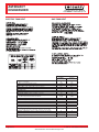
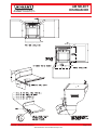
DISHWASHER
PAR
ARTS
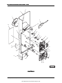
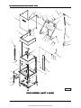
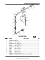
CONTROLS
ILLUS.
PL-57404
1
2
3
4
5
6
7
8
9
10
11
12
13
14
15
16
17
18
19
20
21
22
23
24
25
26
27
28
29
PAR
T NO.
ART
00-893113
00-526454
00-892458
00-294677-00003
NS-047-94
00-294677-00003
NS-011-18
NS-031-16
00-892720-00002
00-892932
NS-031-50
00-892720-00002
00-892934-00001
NS-031-50
FE-022-29
FE-026-30
00-118349-00007
00-118349-00007
NS-047-94
00-294677-00003
00-893642
0F-035324
0F-035373
00-438131-00060
00-438131-00042
0F-035331
00-438131-00175
00-892793-00002
00-893447
00-893448
00-893125
00-893126-00001
00-893126-00002
NAME OF P
AR
T
PAR
ART
AMT
AMT..
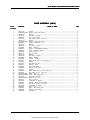
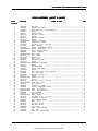
Switch – Membrane Keypad .................................................................................................... 1
Bezel – Display Weldment ....................................................................................................... 1
Tape – Foam ........................................................................................................................... AR
Module – Display ...................................................................................................................... 1
Clamp – Wire ............................................................................................................................ 1
Lock Nut 3/16 Washer Type ...................................................................................................... 1
Clamp – Wire ............................................................................................................................ 1
Nut 10-24 Hex ........................................................................................................................... 1
Stop Nut 10-24 Hex ................................................................................................................. 1
Standoff ...................................................................................................................................... 2
Board – Control Assy. .............................................................................................................. 1
Stop Nut 6-32 Hex ................................................................................................................... 2
Standoff ...................................................................................................................................... 2
Board – Relay Assy. ................................................................................................................ 1
Stop Nut 6-32 Hex ................................................................................................................... 2
Fuse (250 V., 1.0 Amp.) .......................................................................................................... 1
Fuse (250 V., 0.1 Amp.) .......................................................................................................... 1
Standoff – Reed Board (Relay Board) ................................................................................... 2
Standoff – Reed Board (Control Board) ................................................................................. 2
Lock Nut 3/16 Washer Type ...................................................................................................... 4
Clamp – Wire ............................................................................................................................ 4
Plate (Patent Numbers) ............................................................................................................ 1
Label – Warning (Fuse) (Electric Heat) ................................................................................. 1
Label – Warning (Fuse) (Gas Heat) ....................................................................................... 1
Label – Warning (W/Electric Booster) .................................................................................... 1
Label – Warning (W/Gas Heat, W/Electric Booster S.P.E.C., or W/O Electric Booster) . 1
Label (Error Code) .................................................................................................................... 1
Label – Instruction .................................................................................................................... 1
Ribbon Cable Assy. .................................................................................................................. 1
Harness – Sensor Assy. .......................................................................................................... 1
Harness – Relay Board Assy. ................................................................................................. 1
Cable – Rinse Thermistor ........................................................................................................ 1
Cable – Rinse Valve (Without Electric Booster) ................................................................... 1
Cable – Rinse Valve (With Electric Booster) ........................................................................ 1
- 5 -
AM15 Dishwasher Technical Manual Page 41 of 83
F-43094 (October 2004)