1
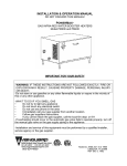
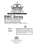
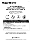
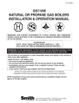
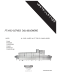
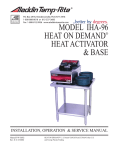
I
N
S
T
R
U
C
T
INFRARED
BOOSTER
I
O
N
S
INFRARED BOOSTER
. . . Gas Water Heaters
MODEL
IB57
IB140
IB235
IB290
ML-110898
ML-110899
ML-110861
ML-110862
701 S. RIDGE AVENUE
TROY, OHIO 45374-0001
937 332-3000
–1–
www.hobartcorp.com
FORM 34070 Rev. C (10-99)
IMPORTANT FOR YOUR SAFETY
WARNING: IF THE INFORMATION IN THESE
INSTRUCTIONS IS NOT FOLLOWED EXACTLY,
A FIRE OR EXPLOSION MAY RESULT CAUSING
PROPERTY DAMAGE, PERSONAL INJURY OR
DEATH.
DO NOT STORE OR USE GASOLINE OR OTHER
FLAMMABLE VAPORS AND LIQUIDS IN THE
VICINITY OF THIS OR ANY OTHER APPLIANCE.
WHAT TO DO IF YOU SMELL GAS
• Do not try to light any appliance.
• Do not touch any electrical switch; do not use
any phone in your building.
• Immediately call your gas supplier from a
neighbor's phone. Follow the gas supplier's
instructions.
• If you cannot reach your gas supplier, call the
fire department.
INSTALLATION AND SERVICE MUST BE
PERFORMED BY A QUALIFIED INSTALLER,
SERVICE AGENCY, OR THE GAS SUPPLIER.
Installer: Affix these Instructions adjacent to the appliance.
Customer: Save these Instructions for future reference.
© HOBART CORPORATION 1998, 1999
–2–
TABLE OF CONTENTS
IMPORTANT FOR YOUR SAFETY . . . . . . . . . . . . . . . . . . . . . . . . . . . . . . . . . . . . . . . . . . . . . 2
GENERAL
............................................................... 4
Delivery Rates at 180°F . . . . . . . . . . . . . . . . . . . . . . . . . . . . . . . . . . . . . . . . . . . . . . . . . 4
INSTALLATION . . . . . . . . . . . . . . . . . . . . . . . . . . . . . . . . . . . . . . . . . . . . . . . . . . . . . . . . . . . . . 5
Unpacking . . . . . . . . . . . . . . . . . . . . . . . . . . . . . . . . . . . . . . . . . . . . . . . . . . . . . . . . . . . . 5
Installation Codes. . . . . . . . . . . . . . . . . . . . . . . . . . . . . . . . . . . . . . . . . . . . . . . . . . . . . . 5
Location . . . . . . . . . . . . . . . . . . . . . . . . . . . . . . . . . . . . . . . . . . . . . . . . . . . . . . . . . . . . . 5
Clearance Dimensions . . . . . . . . . . . . . . . . . . . . . . . . . . . . . . . . . . . . . . . . . . . . . . . . . . 5
Leveling . . . . . . . . . . . . . . . . . . . . . . . . . . . . . . . . . . . . . . . . . . . . . . . . . . . . . . . . . . . . . 5
Combustion / Ventilation Air . . . . . . . . . . . . . . . . . . . . . . . . . . . . . . . . . . . . . . . . . . . . . 5
Venting Requirements . . . . . . . . . . . . . . . . . . . . . . . . . . . . . . . . . . . . . . . . . . . . . . . . . . 6
Acceptable Vent Piping . . . . . . . . . . . . . . . . . . . . . . . . . . . . . . . . . . . . . . . . . . . . . . . . . 6
Gas Connection . . . . . . . . . . . . . . . . . . . . . . . . . . . . . . . . . . . . . . . . . . . . . . . . . . . . . . . 9
Gas Pressure Specifications . . . . . . . . . . . . . . . . . . . . . . . . . . . . . . . . . . . . . . . . . . . . . 9
Water Requirements . . . . . . . . . . . . . . . . . . . . . . . . . . . . . . . . . . . . . . . . . . . . . . . . . . 10
Plumbing Connections . . . . . . . . . . . . . . . . . . . . . . . . . . . . . . . . . . . . . . . . . . . . . . . . . 10
Electrical Connections . . . . . . . . . . . . . . . . . . . . . . . . . . . . . . . . . . . . . . . . . . . . . . . . . 12
Electrical Diagram . . . . . . . . . . . . . . . . . . . . . . . . . . . . . . . . . . . . . . . . . . . . . . . . . . . . 13
Start Up Procedures . . . . . . . . . . . . . . . . . . . . . . . . . . . . . . . . . . . . . . . . . . . . . . . . . . 14
Filling the Booster Piping . . . . . . . . . . . . . . . . . . . . . . . . . . . . . . . . . . . . . . . . . 14
Checking the Circulator . . . . . . . . . . . . . . . . . . . . . . . . . . . . . . . . . . . . . . . . . . . 14
Lighting the Heater . . . . . . . . . . . . . . . . . . . . . . . . . . . . . . . . . . . . . . . . . . . . . . 14
What To Do If You Smell Gas . . . . . . . . . . . . . . . . . . . . . . . . . . . . . . . . . . . . . . 14
Hot Surface Ignition Using the Robertshaw Gas Valve . . . . . . . . . . . . . . . . . . 15
To Turn Off Gas To Heater . . . . . . . . . . . . . . . . . . . . . . . . . . . . . . . . . . . . . . . . 15
OPERATION . . . . . . . . . . . . . . . . . . . . . . . . . . . . . . . . . . . . . . . . . . . . . . . . . . . . . . . . . . . . . . 16
MAINTENANCE . . . . . . . . . . . . . . . . . . . . . . . . . . . . . . . . . . . . . . . . . . . . . . . . . . . . . . . . . . . . 17
Lubrication . . . . . . . . . . . . . . . . . . . . . . . . . . . . . . . . . . . . . . . . . . . . . . . . . . . . . . . . . . 17
Vent System . . . . . . . . . . . . . . . . . . . . . . . . . . . . . . . . . . . . . . . . . . . . . . . . . . . . . . . . . 17
Check Burner Flame . . . . . . . . . . . . . . . . . . . . . . . . . . . . . . . . . . . . . . . . . . . . . . . . . . 17
TROUBLESHOOTING . . . . . . . . . . . . . . . . . . . . . . . . . . . . . . . . . . . . . . . . . . . . . . . . . . . . . . . 17
List of Replacement Parts . . . . . . . . . . . . . . . . . . . . . . . . . . . . . . . . . . . . . . . . . . . . . . 18
Service . . . . . . . . . . . . . . . . . . . . . . . . . . . . . . . . . . . . . . . . . . . . . . . . . . . . . . . . . . . . . 20
–3–
Installation, Operation, and Care of
INFRARED BOOSTER GAS WATER HEATERS
SAVE THESE INSTRUCTIONS
GENERAL
The Infrared Booster Gas Water Heaters (available
for natural gas or propane) provide 180°F rinse water
for commercial dishwashing machines. Health codes
and NSF permit 180°F (minimum temperature) water
to be used as a sanitizing rinse for utensils and
dishware used in restaurants and food-serving
operations. Water enters the gas booster water
heater at the inlet water connection, circulates through
the gas heat exchanger and stainless steel tank, and
constantly maintains the 180°F minimum water
temperature at the outlet connection. The table,
Delivery Rates @ 180°F, indicates the maximum
amount of hot water that can be delivered by the
various Booster Heater models, depending on the
incoming water temperature.
Rinse water volume requirements for various commercial dishwasher models and operating rates are
available from your authorized Hobart dealer.
Model
IB57
IB140
IB235
IB290
Input (Btu/hr)
Natural Gas
57,000
140,000
235,000
290,000
Input (Btu/hr)
Propane
57,000
140,000
235,000
280,000
Tank Capacity
(U.S. Gallons)
9.5
9.5
17.0
17.0
Width x Height x Depth (Inches)
25.375 x 30.125 x 19.50
28.375 x 32.125 x 22.25
36.875 x 32.125 x 22.25
36.875 x 32.125 x 22.25
DELIVERY RATES @ 180° F (assuming 80% efficiency)
Model
IB57
IB140
IB235
IB290
Input
(Btu/hr)
Incoming Water Temperature
Rate
110° F
120° F
130° F
140° F
150° F
57,000
Natural or
Propane
140,000
Natural or
Propane
235,000
Natural or
Propane
290,000
Natural
Gallons per Minute
1.30
1.52
1.82
2.28
3.04
Gallons per Hour
78
91
109
137
182
Gallons per Minute
3.20
3.73
4.48
5.60
7.46
Gallons per Hour
192
224
268
336
448
Gallons per Minute
5.37
6.27
7.52
9.40
12.54
Gallons per Hour
280,000
Propane
Gallons per Minute
322
6.63
398
6.40
384
37 6
7.74
46 4
7.47
448
451
9.28
557
8.96
538
564
11.60
696
11.20
672
752
15.47
928
14.94
896
Gallons per Minute
Gallons per Hour
Gallons per Hour
NOTE: For altitudes above 5000 feet, contact Hobart Product Service, phone (937) 332-2525,
Warewash Technical Support.
–4–
INSTALLATION
UNPACKING
Immediately after unpacking, check for possible shipping damage. If the Booster Heater is found to
be damaged after unpacking, save the packaging material and contact the carrier within 15 days of
delivery.
Prior to installation, test the electrical service to assure that it agrees with the specifications on the data
plate located on the left-front panel of the booster heater. Be sure that the type of gas supplied to the
machine (natural gas or propane) is the same as indicated on the data plate.
INSTALLATION CODES
Installation must be in accordance with state and local codes, or in the absence of local codes, with
the National Fuel Gas Code, ANSI Z223.1 (latest edition) and the National Electrical Code,
ANSI/NFPA 70 (latest edition). In Canada, the installation standards are: CAN/CGA B149.1,
CAN/CGA B149.2, and CSA C22.2 No.1 (latest editions).
LOCATION
Locate the IB Series Booster Water Heater so that the required clearance dimensions are maintained.
Keep the appliance area clear and free from combustible materials, gasoline and other flammable
vapors and liquids. The booster heater should not be located in an area where water leakage will result
in damage to the area adjacent to it or to lower floors of the structure. Where such areas cannot be
avoided, install a suitable catch pan, adequately drained, under the heater. The pan must not restrict
combustion air flow. Do not install heater directly on carpeting.
CLEARANCE DIMENSIONS
FLOOR TOP
LEFT SIDE
Allowable
6" *
0"
2"
RIGHT SIDE
Recommended
Recommended
Allowable
for Service
for Service
20"
2"
10"
FRONT
Alcove**
BACK
7"
VENT
Combustible
Construction
6" Horizontal
1
/2" Vertical
NonCombustible
Construction
1
/2" Horizontal
1
/2" Vertical
* Approved for installation on combustible flooring (6" legs provide required clearance).
** A front clearance of at least 24" is recommended for adequate service of controls.
LEVELING
Four legs are welded to the bottom corners of the frame to provide the required six-inch floor clearance.
Adjustable feet at the bottom of the four legs should be rotated in or out as required to level the booster
heater front-to-back and side-to-side in its final location.
COMBUSTION / VENTILATION AIR
CAUTION: Combustion air must not be contaminated by corrosive chemical fumes which can
damage the heater.
An adequate supply of air for proper combustion and ventilation must be provided in accordance with
the National Fuel Gas Code, ANSI Z223.1, or applicable building codes. Do not obstruct the flow of
combustion and ventilation air to the heater.
–5–
VENTING REQUIREMENTS
WARNING: PROVIDE A SCREEN OR BARRIER TO PREVENT PERSONAL INJURY IN AREAS
WHERE INADVERTENT PERSONNEL CONTACT WITH THE HOT VENT PIPE CAN OCCUR.
Models IB57 and IB140 are Category IV (positive flue
pressure, excessive condensate, and flue gas
temperature at the heater outlet approximately 330°F).
Models IB235 and IB290 are Category III (positive flue
pressure, not excessive condensate, and flue gas
temperature at the heater outlet approximately
530°F). The vent outlet on the booster heater is 3
inches in diameter. Models IB57 and IB140 require
3 inch minimum vent pipe throughout. Models IB235
and IB290 require 4 inch minimum vent pipe; the 3
inch adjustable vent pipe elbow and the 3 inch to 4
inch vent pipe adapter (provided on IB235 and IB290)
are to be installed at the vent outlet of the booster
heater (Fig. 1). On all models, 1/4 inch per foot minimum
incline must be maintained.
Models IB235 & IB290 Only
Water Out
Gas
3 to 4 Inch
Adapter
Water In
3 Inch Elbow
Vent
Temperature and
Pressure Relief Valve
Fig. 1
PL-53440
Vent piping must be one of the types mentioned in this manual and must be properly installed according
to the vent pipe manufacturer's instructions. Each vent joint must be properly sealed and secured so
it stays in place.
ACCEPTABLE VENT PIPING
MANUFACTURER
MODEL
Heat-Fab Inc.
38 Haywood St.
Saf-T-Vent
Greenfield, MA 01301
Z-Flex US, Inc.
20 Commerce Park North
Z-Vent
Bedford, NH 03110
MATERIAL
SPECIFICATION
AL 29-4C*
Stainless Steel
AL 29-4C*
Stainless Steel
TERMINATION
Part Name
IB57 or IB140
TERMINATION
Part Number
IB235 or IB290
TERMINATION
Part Number
Tee
7390TEE
7490TEE
Rain Cap
5300C1
5400C1
Mitre / Straight
7390GC
-Tee
#02SVSTTX-3 #02SVSTTX-4
Rain Cap
#02VRSRCX03 #02VRSRCX04
Termination Box #02SVSRTX-3 #02SVSRTX-4
* AL 29-4C is a registered trademark of Allegheny Ludlum Corp.
Per the National Fuel Gas Code, ANSI Z223.1, the heater must be vented in one of three ways:
1. Into the exhaust system (Fig. 2). The vent pipe must not penetrate the filter. When the heater is
vented into the exhaust system, an electrical interlock must be provided (by others) to allow the flow
of gas to the booster heater burner ONLY when the exhaust system is functioning. Refer to APS1
and APS2 on the wiring diagram in the control box accessed by removing the left side panel (also
refer to pages 12 and 13).
2. Through the sidewall, or the ceiling (Fig. 3). Type B-1 vent pipe (4 inch minimum diameter for IB57
and IB140, 5 inch minimum diameter for IB235 and IB290) may be used when venting vertically,
provided a one inch minimum clearance to combustible construction is maintained and the
termination above the roof uses a listed wind cap.
3. Freely vented into the room or space where it is installed (Fig. 4), provided that:
a. A mechanical exhaust system is present in the kitchen,
b. The flue outlet of the booster water heater is at least 36 inches vertically and 6 inches
horizontally distant from any surface other than the booster / or dishwasher, and
c. Any or all gas fired equipment is installed so the total BTU input rating of the unvented gas
appliance(s) divided by the total cubic feet of the room area (including any areas adjacent that
cannot be closed off) does not exceed 20 BTU per hour per cubic foot.
–6–
Vent Hood
Dishwasher
Dish Table
or Conveyor
Vent Pipe
3 to 4 Inch
Adapter
Required For
IB235 and IB290
PL-53441
Fig. 2
Termination Tee
Combustible
Sidewall
Termination
Termination Tee
Dish Table
or Conveyor
Dishwasher
6"
Non-Combustible
Sidewall
Termination
Thru-Wall
Fitting
Termination Tee
6"
3 to 4 Inch
Adapter Required
For IB235 and IB290
Fig. 3
–7–
PL-53442
Termination Tee
Dish Table
or Conveyor
Vent Pipe
3 to 4 Inch
Adapter Required
For IB235 and IB290
PL-53443
Fig. 4
All horizontal runs of the vent pipe shall have a minimum rise of 1/4" per foot of length and should be
supported every 5 feet or less (for Canada, every 3 feet) and at every elbow.
For horizontal venting of models IB57 and IB140, the total length of 3-inch diameter vent pipe can be
up to 70 feet with up to four 90° elbows and one termination vent. For horizontal venting of models
IB235 or IB290, the total length of 4-inch diameter vent pipe can be up to 70 feet with up to four 90°
elbows and one termination vent. For each additional elbow, reduce the total pipe length by 10 feet.
The minimum length is 2 feet. For vertical venting: The maximum length of 3" or 4" diameter vent pipe
described above should be followed; the same requirements for elbows and termination vent apply; the
minimum length for vertical venting is 5 feet.
For sidewall venting, locate the heater as close as possible to the wall being used. The maximum and
minimum wall thickness is determined by the wall thimble available from the vent manufacturer. Refer
to the vent manufacturer's installation instructions.
When a draft hood is used, it must be in the same atmospheric pressure zone as the combustion air
inlet of the booster water heater.
Additional requirements when venting through a sidewall:
• The vent terminal shall be located at least three feet above any forced air inlet located within ten
feet; or at least four feet below, four feet horizontally from, or one foot above any door, window,
or gravity air inlet into any building. It shall also have a minimum horizontal clearance of four feet
from electric meters, gas meters, regulators, relief valves, or other equipment.
• The vent terminal shall be located not less than seven feet above grade when it is adjacent to public
walkways.
• The bottom of the vent terminal shall be located at least twelve inches above grade or ground, or
the normally expected snow accumulation level. The snow level may be higher on walls exposed
to prevailing winds.
• Avoid areas where local experience indicates that condensate drippage may cause problems, such
as the following: Above planters, patios, public walkways, or areas where condensate or vapor
could create a nuisance or hazard, or where its discharge could be detrimental to the operation of
regulators, relief valves, or other equipment.
–8–
GAS CONNECTION
For model IB57, the gas inlet pipe size is 1/2" NPT at the gas valve. For models IB140, IB235, and IB290,
the gas inlet pipe size is 3/4" NPT at the gas valve. The gas supply line must be sized to adequately
provide the input BTU/Hr rate for that model at the specified flowing pressure (see table).
The maximum inlet gas pressure must not exceed
the Max value shown in the chart at right. The
Min value is for the purposes of input adjustment.
The gas valve (Fig. 5) is provided with a pressure
tap to measure the gas pressure downstream,
which is also the manifold pressure.
Gas supply piping must have a sediment trap
and a manual shutoff valve (supplied by others)
installed outside of the rear cover panel, ahead
of the booster heater's gas control (Fig. 5).
GAS PRESSURE SPECIFICATIONS
[ FLOWING GAS PRESSURE — NOT STATIC ]
Inches W.C. (Water Column)
Model
Type of Gas
IB57, IB140,
IB235, IB290
Natural Gas
IB57, IB140,
IB235, IB290
Propane
Incoming Line Pressure
Minimum
Maximum
Manifold
Pressure
4.5
14.0
3.2
11
13
3.2
NOTE: DO NOT use teflon tape on gas line pipe threads. For gas line pipe connections, use
LOCTITE 565, Hobart part 546292, or a flexible sealant suitable for use with Natural and LP Gases.
The heater and its gas connections must be leak tested before placing the appliance in operation. Use
soapy water for leak test. DO NOT use open flame.
The heater and its individual shutoff valve must be disconnected from the gas supply piping system
during any pressure testing of that system at test pressures in excess of 1/2 psig (3.5 kPa).
The heater must be isolated from the gas supply piping system by closing its individual manual shutoff
valve during any pressure testing of the gas supply piping system at test pressures equal to or less than
1
/2 psig (3.5 kPa).
Dissipate test pressure from the gas supply line before re-connecting the heater and its manual shutoff
valve to the gas supply line. Caution: Failure to follow this procedure may damage the gas valve.
Model IB57
Models IB140 and IB235
Manual Valve
Manual Valve
Model IB290
Manual Valve
NO
NO
Gas Valve
Gas Valve
Rear Panel
Sediment Trap
OFF
Rear Panel
Sediment Trap
OFF
Gas Valve
Rear Panel
Sediment Trap
PL-53289
Fig. 5
–9–
WATER REQUIREMENTS
Proper water quality can improve ware washing performance by reducing spotting, lowering chemical
supply costs, enhancing effectiveness of labor, and extending equipment life. Local water conditions
vary from one location to another. The recommended proper water treatment for effective and efficient
use of this equipment will also vary depending on the local water conditions. Ask your municipal water
supplier for details about local water specifics prior to installation.
Recommended water hardness is 4 – 6 grains of hardness per gallon. Chlorides must not exceed 50
parts per million. Water hardness above 6 grains per gallon should be treated by a water conditioner
(water softener or in-line treatment). Water hardness below 4 grains per gallon also requires a water
treatment to reduce corrosion. Water treatment has been shown to reduce costs associated with
machine cleaning, reduce deliming of the dishwasher, reduce detergent usage, and reduce corrosion
of metallic surfaces in the booster water heater and dishwasher.
Sediment, silica, chlorides, or other dissolved solids may lead to a recommendation for particulate
filtration or reverse osmosis treatment.
If an inspection of the booster reveals lime build-up after installation, in-line water treatment should be
considered, and, if recommended, should be installed and used as directed. Contact your Hobart
Service office for specific recommendations.
PLUMBING CONNECTIONS
WARNING: PLUMBING CONNECTIONS MUST COMPLY WITH APPLICABLE SANITARY, SAFETY,
AND PLUMBING CODES.
The inlet and outlet water connections are 3/4 inch NPT. The inlet water supplied to the booster heater
must be a minimum of 110°F. Do not connect to cold water supply. Recommended flowing water
pressure to the booster heater is 20 psig. Minimum is 15 psig; maximum is 25 psig. If a water pressure
regulator is used to regulate the water pressure, adjust to maintain 20 psig at the dishwasher. A water
pressure regulator, pressure gauge, and water shock absorber are provided by Hobart when ordered
in an optional accessory Water Hammer Arrestor Kit.
Install a suitable water hammer arrester between the booster heater and dishwasher (Figs. 6 and 7).
A 3/4 inch NPT drain valve is provided underneath the booster heater to allow the tank to be drained,
if needed during servicing. This drain connection may be plumbed to a suitable open floor drain.
The Temperature and Pressure Relief Valve is located at the rear of the booster heater. Install a pipe
from the discharge connection on the Temperature and Pressure Relief Valve to a suitable drain or
catch pan with drain. The discharge connection on the Temperature and Pressure Relief Valve is
3
/4 inch NPT on IB57 and IB140; the connection is 1 inch NPT on IB235 and IB290. Refer to the Tag
on the Temperature and Pressure Relief Valve for additional drain installation instructions.
The Temperature and Pressure Relief Valve should be manually operated at least once annually to
make sure that the valve mechanism is still functional. Use care when operating the relief valve. Follow
instructions on the tag located on the Temperature and Pressure Relief Valve to avoid contact with hot
water discharge and to prevent water damage from operation of the valve.
Repair or alteration of the Temperature and Pressure Relief Valve in any way is prohibited by national
safety standards / local codes.
If the Temperature and Pressure Relief Valve discharges occasionally or periodically, this may be due
to thermal expansion in a closed water supply system. Contact the water supplier or the local plumbing
inspector regarding how to correct this situation. DO NOT plug the relief valve or install a shutoff valve
in the discharge drain line.
– 10 –
SHOWN WITH OPTIONAL WATER HAMMER ARRESTOR KIT
Union
Water Shock
Absorber
Ball
Valve
180 F to
Dishwasher
Pressure
Gauge
140 F
Inlet
Floor Drain
Union
Ball Valve
Pressure
Regulator
PL-53294
Fig. 6
The heater is equipped with a pump which circulates water inside the booster heater and maintains a
uniform water temperature in the tank. Depending on the distance from the heater to the dishwasher,
it may be necessary to run empty rack(s) to purge the supply line if the indicated rinse water
temperature is lower than the required 180°F. For this reason, it is best to locate the booster heater
as close as possible to the dishwasher. If the booster heater is located more than 10 feet from the
dishwasher, an additional recirculation system (supplied by others) may be installed (Fig. 7).
SHOWN WITH OPTIONAL WATER HAMMER ARRESTOR KIT
Pump &
Motor
Union
180 F to
Dishwasher
Ball
Valve
Water Shock
Absorber
Pressure
Gauge
SUGGESTED PUMP FLOW: 2 – 5 GPM.
CONSULT PLUMBER FOR SPECIFIC
RECOMMENDATIONS.
140 F
Inlet
Floor Drain
Ball Valve
Union
Pressure
Regulator
TYPICAL PIPING FOR RECIRCULATION SYSTEM
WHEN BOOSTER HEATER IS GREATER THAN 10 FEET FROM DISHWASHER
Fig. 7
– 11 –
PL-53293
ELECTRICAL CONNECTIONS
WARNING: ELECTRICAL AND GROUNDING CONNECTIONS MUST COMPLY WITH APPLICABLE
PORTIONS OF THE NATIONAL ELECTRICAL CODE AND/OR OTHER ELECTRICAL CODES.
WARNING: DISCONNECT THE ELECTRICAL POWER SUPPLY AND PLACE A TAG AT THE
DISCONNECT SWITCH INDICATING THAT THE CIRCUIT IS BEING WORKED ON.
The electrical power supply requirement for the heater is 120 Volts, 60 Hz, 1 Phase. Minimum
conductor ampacity and maximum protective device should be rated 15 Amperes. The electrical power
for the gas booster water heater must be supplied independent of the dishwasher, whether the booster
is switched on and off with a manual switch (on the Stand Alone unit only) or by the dishwasher control
circuit (on the Dishwasher Activated unit only). Properly sized conduit and 14 AWG wire rated for at
least 90°C must be used for wiring connections.
Polarity must be observed for the heater to operate properly: Connect the hot Black wire to [ L1 ], the
White Neutral wire to [ N ], and the Green wire to the Ground lug. Consult wiring diagram accessed
by removing the left-front panel. Provide a separate fused circuit from the main electrical panel to the
heater. Also, provide a means of disconnecting the electrical supply within sight of the heater. Keep
wires away from vent.
When connecting a Dishwasher Activated gas booster water heater to the control panel on a
commercial dishwasher, use the connection points labeled BSTR1 and BSTR2 on the booster. Only
connect a Dishwasher Activated gas booster water heater (not a Stand Alone) to a dishwasher that has
been provided with a properly labeled connection point. Refer to the instruction manual for the
dishwasher (under Gas Booster Water Heater Option) to determine if this option is available and what
is the proper connection point on the dishwasher.
Model IB57 uses either a 24 Volt or 120 Volt inter-connect circuit for Dishwasher Activated boosters,
depending on the pilot circuit of the dishwasher model it is to be connected with. Models IB140, IB235,
and IB290 use only a 120 Volt inter-connect circuit for Dishwasher Activated boosters. A Dishwasher
Activated gas booster water heater should only be used with a dishwasher that is provided with the
capability of connecting the gas booster water heater as an accessory.
When the gas booster water heater is connected to the vent fan control switch, the vent fan is switched
on when the gas booster water heater is activated and off when the heater is off. Use connections VFC1
and VFC2 on the gas booster water heater if connecting to the vent fan control switch.
When the actual flow in the flue must be sensed to permit operation of the burner only when the vent
system is operating, use connections APS1 and APS2 on the gas booster water heater to connect to
an Air Pressure Switch. When making this connection, it is necessary to remove the jumper from
1TB-APS1 and 1TB-APS2. The air pressure switch is provided by others.
– 12 –
– 13 –
START UP PROCEDURES — FOR YOUR SAFETY READ BEFORE OPERATING
Filling the Booster Piping
Fill the booster heater with water, purging all air. Make sure water is flowing through the booster to
the dishwasher's fill or final rinse before lighting the booster heater by either leaving the main power
switch off on Stand Alone units or leaving the manual gas valve closed on Dishwasher Activated units.
Checking the Circulator
•
Before lighting the heater, make sure the water pump is operating properly.
•
With the gas valve in the off position, activate the power switch. If no power switch is present,
activate the dishwasher making a demand for hot rinse water.
•
The pump should start immediately. Allow the circulator to pump water through the system.
Lighting the Heater
CAUTION: Liquefied petroleum gas is heavier than air and sinks to the ground. Exercise
extreme care in lighting the heater in confined areas.
WARNING: IF YOU DO NOT FOLLOW THESE INSTRUCTIONS EXACTLY, A FIRE OR EXPLOSION
MAY RESULT CAUSING PROPERTY DAMAGE, PERSONAL INJURY, OR LOSS OF LIFE.
This heater DOES NOT have a pilot. It is equipped with a hot surface ignition device which
automatically lights the burner. DO NOT attempt to light the burner by hand.
Before operating, smell all around the heater area for gas. Be sure to smell next to the floor because
some gases are heavier than air and will settle on the floor.
WHAT TO DO IF YOU SMELL GAS
•
Do not try to light any appliance.
•
Do not touch any electric switch.
•
Do not use any phone in your building.
•
Immediately call your gas supplier from a neighbor's phone. Follow the gas supplier's instructions.
•
If you cannot reach your gas supplier, call the fire department.
Use only your hand to push in, move, or turn the gas control knob or lever. Never use tools. If the
knob or lever will not push in, move, or turn by hand, do not try to repair it. Call a qualified service
technician. Force or attempted repair may result in a fire or explosion.
Do not use this heater if any part has been under water. Immediately call a qualified service
technician to inspect the heater and replace any part of the control system and any gas control that
has been under water.
– 14 –
Hot Surface Ignition Using the Robertshaw Gas Valve
1. STOP! Read the safety information.
Model IB57
2. Turn off all electrical power to the appliance.
3. Remove the left side panel.
5. Turn the gas control knob clockwise
the "OFF" position.
Gas Valve
Gas Control Knob
4. This appliance is equipped with an ignition
device which automatically lights the
burners. DO NOT try to light the burners
by hand.
to
6. Wait five (5) minutes to clear out any gas.
If you then smell gas, stop and follow the
instructions What To Do If You Smell Gas
(page 14). If you do not smell gas, go to
the next step.
Models IB140 and IB235
Gas Control Knob
7. Turn the gas control lever counterto the "ON" position.
clockwise
NO
OFF
8. Replace the left side panel.
9. Turn on all electric power to the appliance.
10. If the appliance will not operate, follow the
instructions To Turn Off Gas To Heater
(below) and call your service technician or
gas supplier.
Gas Valve
Model IB290
Gas Control Knob
To Turn Off Gas To Heater
NO
1. Turn off all the electric power to the heater
if service is to be performed.
OFF
2. Remove the left side panel.
3. Push in and turn the gas control lever
to the "OFF" position.
clockwise
Gas Valve
PL-53290
4. Replace the left side panel.
Fig. 8
WARNING: SHOULD OVERHEATING OCCUR OR THE GAS SUPPLY FAIL TO SHUT OFF, DO NOT
TURN OFF OR DISCONNECT THE ELECTRICAL SUPPLY TO THE PUMP. SHUT OFF THE GAS
SUPPLY AT THE MANUAL GAS CONTROL VALVE.
– 15 –
OPERATION
The booster heater is designed to deliver 180°F water, up to the gallons per minute and gallons per
hour ratings specified in the table on page 4, depending on the incoming water temperature and
Booster Heater model and its input BTU/Hr.
Provided the necessary power, water, gas, and vent connections are completed, a STAND ALONE unit
is started by the activation of the On / Off Switch located on the front (Fig. 9). Provided the necessary
power, water, gas, and vent connections are completed, the DISHWASHER ACTIVATED unit will be On when
the dishwasher power switch is On. The Green indicator light is lit and the circulator pump turns on
when power to the booster heater is On. The blower motor will start after about 6 seconds if the
thermostat calls for heat.
Provided that the operating and safety controls including any vent switches are closed and that the
thermostat is calling for heat, the Amber indicator light is lit. ☛ The blower turns on for about 10
seconds, providing clean air in the combustion chamber. Then the gas valve opens and the hot surface
ignitor heats up for four seconds. With ignition, the flame sensor will detect that the burner flame has
been established. If the burner flame is not sensed within a few seconds, the circuit repeats the
process from ☛ for a total of three trial ignitions before the gas valve shuts off and requires reset.
To reset the ignition safety shutoff, momentarily turn the power switch off and then back on. If no power
switch is present, turn the dishwasher off for one minute and then turn the dishwasher back on. When
the water temperature exceeds the setting of the operating temperature control (thermostat board
assembly), the burner will shut off until the next call for heat. The operating temperature control
(thermostat board assembly) is factory set at 185°F.
On STAND ALONE units, the circulator pump will stay on as long as the On / Off Switch is on. On
DISHWASHER ACTIVATED units, pump will stay on as long as the dishwasher is on. The blower is on when
the thermostat is calling for heat and for 30 seconds after it is satisfied.
Flame
Observation
Port
Amber Indicator Light –
Heat is being demanded.
Green Indicator Light –
The Booster Heater has power.
On / Off Switch –
Present only on Stand Alone Units.
NOTE:
Dishwasher Activated
units do not have an On/Off Switch
The booster heater starts when the
dishwasher power is on.
PL-53172
Fig. 9
– 16 –
MAINTENANCE
LUBRICATION
The water pump motor and the combustion air blower motor are permanently lubricated and require
no other maintenance.
VENT SYSTEM
Annually check the vent system for obstruction. Check for signs of deformation in the vent pipes which
will be an indication of abnormal conditions in the venting system. Refer to the instructions supplied
by the vent pipe manufacturer.
CHECK BURNER FLAME
When the burner is operating properly the flame will appear to be orange with a blue tint as you look
across the burner. This can be observed through the flame observation port with the left side panel
removed (Fig. 9). Inspect the burner through the observation port periodically. If areas of the burner
are other than described, contact your Hobart-authorized service office to have the burner inspected
for proper operation.
TROUBLESHOOTING
PROBLEM
POSSIBLE CAUSE
SUGGESTED SOLUTION
On - Off switch energized.
Unit does not operate.
No power to heater.
Vent fan off (APS interlock).
Check circuit breaker.
Check disconnect switch.
Check water supply.
Check manual reset switch in unit (call Service).
Turn vent fan on.
Blocked vent.
Gas off.
Remove blockage.
Turn gas on.
Unit energized, pump and
blower running but burners
are NOT on.
– 17 –
LIST OF REPLACEMENT PARTS
When ordering parts, be sure to provide the Model Number, ML Number, and Serial Number from the
data plate located on the left-front panel of the booster heater. NOTE: As continued product
improvement is a policy of the manufacturer, part numbers may change without notification. For the
latest part numbers, contact your Hobart-authorized service office.
NOTE: 57,000 BTU/Hr, 140,000 BTU/Hr & 235,000 BTU/Hr sizes apply to Natural Gas and Propane; 280,000 BTU/Hr
applies to Propane only; and 290,000 BTU/Hr applies to Natural Gas only — unless specified otherwise.
Insulation - Flue
PART No.
NAME OF PART
00
00
00
00
00
00
00
00
00
00
00
00
PLATE-PLUG (57,000 BTU/Hr) . . . . . . . . . . . . . . . . . . . . . . . . . . . . . . . . . . . . . . . . . . . .
PLATE-PLUG (140,000; 235,000; 280,000; & 290,000 BTU/Hr) . . . . . . . . . . . . . . . . .
PLUG-COIL (INSULATION) (57,000 BTU/Hr) . . . . . . . . . . . . . . . . . . . . . . . . . . . . . . . .
PLUG-COIL (INSULATION) (140,000; 235,000; 280,000 & 290,000 BTU/Hr) . . . . . .
RETAINER-PLUG (57,000 BTU/Hr) . . . . . . . . . . . . . . . . . . . . . . . . . . . . . . . . . . . . . . . .
RETAINER-PLUG (140,000; 235,000; 280,000 & 290,000 BTU/Hr) . . . . . . . . . . . . . .
RETAINING CLIP-INSULATION . . . . . . . . . . . . . . . . . . . . . . . . . . . . . . . . . . . . . . . . . . .
INSULATION-TAPE (LINEAR FEET) . . . . . . . . . . . . . . . . . . . . . . . . . . . . . . . . . . . . . . .
CAP, EXHAUST (57,000 BTU/Hr) . . . . . . . . . . . . . . . . . . . . . . . . . . . . . . . . . . . . . . . . . .
CAP, EXHAUST (140,000 ; 235,000; 280,000 & 290,000 BTU/Hr) . . . . . . . . . . . . . . .
INSULATION, EXHAUST (57,000 BTU/Hr) . . . . . . . . . . . . . . . . . . . . . . . . . . . . . . . . . .
INSULATION, EXHAUST (140,000; 235,000; 280,000 & 290,000 BTU/Hr) . . . . . . . .
749072
748680
749076
748567
749143
748682
748551
548677
749065
748870
749064
749051
AMT
1
1
1
1
2
2
17
5
1
1
1
1
Components (Pump Side)
PART No.
NAME OF PART
00
00
00
00
00
00
00
00
00
00
00
00
00
00
00
00
00
00
00
00
00
00
00
00
FP
00
BURNER (57,000 BTU/Hr) . . . . . . . . . . . . . . . . . . . . . . . . . . . . . . . . . . . . . . . . . . . . . . .
BURNER (140,000 BTU/Hr) . . . . . . . . . . . . . . . . . . . . . . . . . . . . . . . . . . . . . . . . . . . . . .
BURNER (235,000 BTU/Hr) . . . . . . . . . . . . . . . . . . . . . . . . . . . . . . . . . . . . . . . . . . . . . .
BURNER (280,000 & 290,000 BTU/Hr) . . . . . . . . . . . . . . . . . . . . . . . . . . . . . . . . . . . . .
BLOWER (57,000 & 140,000 BTU/Hr) . . . . . . . . . . . . . . . . . . . . . . . . . . . . . . . . . . . . . .
BLOWER (235,000 BTU/Hr) . . . . . . . . . . . . . . . . . . . . . . . . . . . . . . . . . . . . . . . . . . . . . .
BLOWER (280,000 & 290,000 BTU/Hr) . . . . . . . . . . . . . . . . . . . . . . . . . . . . . . . . . . . . .
RESTRICTOR PLATE (57,000 BTU/Hr Propane) . . . . . . . . . . . . . . . . . . . . . . . . . . . . .
RESTRICTOR PLATE (140,000 BTU/Hr Propane) . . . . . . . . . . . . . . . . . . . . . . . . . . . .
RESTRICTOR PLATE (57,000 BTU/Hr Natural) . . . . . . . . . . . . . . . . . . . . . . . . . . . . . .
RESTRICTOR PLATE (140,000 BTU/Hr Natural) . . . . . . . . . . . . . . . . . . . . . . . . . . . . .
RESTRICTOR PLATE (235,000 BTU/Hr Natural + Propane) . . . . . . . . . . . . . . . . . . . .
RESTRICTOR PLATE (290,000 BTU/Hr Natural + 280,000 BTU/Hr Propane) . . . . . .
FITTING-ORIFICE (57,000 BTU/Hr Natural) . . . . . . . . . . . . . . . . . . . . . . . . . . . . . . . . .
FITTING-ORIFICE (57,000 BTU/Hr Propane) . . . . . . . . . . . . . . . . . . . . . . . . . . . . . . . .
FITTING-ORIFICE (140,000 BTU/Hr Propane) . . . . . . . . . . . . . . . . . . . . . . . . . . . . . . .
FITTING-ORIFICE (235,000 BTU/Hr Propane) . . . . . . . . . . . . . . . . . . . . . . . . . . . . . . .
FITTING-ORIFICE (280,000 BTU/Hr Propane) . . . . . . . . . . . . . . . . . . . . . . . . . . . . . . .
FITTING-ORIFICE (140,000 BTU/Hr Natural) . . . . . . . . . . . . . . . . . . . . . . . . . . . . . . . .
FITTING-ORIFICE (235,000 BTU/Hr Natural) . . . . . . . . . . . . . . . . . . . . . . . . . . . . . . . .
FITTING-ORIFICE (290,000 BTU/Hr Natural) . . . . . . . . . . . . . . . . . . . . . . . . . . . . . . . .
VALVE-GAS BOOSTER (57,000 BTU/Hr Natural + Propane) . . . . . . . . . . . . . . . . . . .
VALVE-GAS BOOSTER (140,000 & 235,000 BTU/Hr Natural + Propane) . . . . . . . . .
VALVE-GAS BOOSTER (290,000 BTU/Hr Natural + 280,000 BTU/Hr Propane) . . . .
FITTING-TUBE 5/8 TBG x 3/4 MPT STRAIGHT (140,000 & 235,000 BTU/Hr) . . . . . . . . . . .
TUBE-GAS (140,000 & 235,000 BTU/Hr) . . . . . . . . . . . . . . . . . . . . . . . . . . . . . . . . . . . .
749071
748560
748579
748560
476846
748561
748584
748583
748583
748583
748583
748583
748583
749110
749110
748564
748564
748564
748564
748564
748564
748863
748563
748588
089-27
748591
00006
00005
00004
00003
00002
00001
00002
00006
00005
00004
00003
00002
00001
AMT
– 18 –
1
1
1
1
1
1
1
1
1
1
1
1
1
1
1
1
1
1
1
1
1
1
1
1
1
1
Components (Pump Side) continued
PART No.
FP
FP
FP
FP
FP
00
FP
FP
00
00
FP
00
00
00
00
00
00
00
00
00
00
00
00
00
00
00
00
00
00
00
00
00
00
00
00
00
00
00
00
00
00
00
00
00
00
00
00
00
00
00
00
047-12
012-45
027-22
077-27
012-07
748593
047-12
012-45
748853
748549
084-53
749111
748570
748570
748570
748570
748575
748575
748575
748575
748576
748576
748576
748576
749100
476847
748574
749099
476848
748577
476395
476237
546292
749077
748569
748571
748572
748562
748562
748562
548679
548251
748550
294700
294700
749120
748685
749119
088196
112235
112235
NAME OF PART
AMT
5
00002
00002
00002
00006
00005
00002
00002
00003
00001
013-1
013-3
006-1
00023
00059
FITTING-TUBE /8 TBG FERRULE (140,000 & 235,000 BTU/Hr) . . . . . . . . . . . . . . . . . . .
FITTING-TUBE 5/8 TBG NUT (140,000 & 235,000 BTU/Hr) . . . . . . . . . . . . . . . . . . . . . . .
BUSHING-PIPE 3/4 TO 1/2 (280,000 & 290,000 BTU/Hr) . . . . . . . . . . . . . . . . . . . . . . . . .
ADAPTER-PIPE 1/2 FPT x 1/2 MPT (280,000 & 290,000 BTU/Hr) . . . . . . . . . . . . . . . . . . .
FITTING, TUBE 5/8 TBG x 1/2 MPT 90° ELBOW (280,000 & 290,000 BTU/Hr) . . . . . . . . . . .
TUBE, GAS (280,000 & 290,000 BTU/Hr) . . . . . . . . . . . . . . . . . . . . . . . . . . . . . . . . . . .
FITTING, TUBE 5/8 TBG FERRULE (280,000 & 290,000 BTU/Hr) . . . . . . . . . . . . . . . . . . .
FITTING, TUBE 5/8 TBG NUT (280,000 & 290,000 BTU/Hr) . . . . . . . . . . . . . . . . . . . . . . .
INSULATION-TANK (140,000 BTU/Hr) . . . . . . . . . . . . . . . . . . . . . . . . . . . . . . . . . . . . .
INSULATION-TANK (235,000; 280,000 & 290,000 BTU/Hr) . . . . . . . . . . . . . . . . . . . .
FITTING, TUBE 3/8 TBG x 1/2 MPT STRAIGHT (57,000 BTU/Hr) . . . . . . . . . . . . . . . . . . . . .
TUBE, GAS (57,000 BTU/Hr) . . . . . . . . . . . . . . . . . . . . . . . . . . . . . . . . . . . . . . . . . . . . .
GASKET-COIL FRONT (57,000 BTU/Hr) . . . . . . . . . . . . . . . . . . . . . . . . . . . . . . . . . . . .
GASKET-COIL REAR (57,000 BTU/Hr) . . . . . . . . . . . . . . . . . . . . . . . . . . . . . . . . . . . . .
GASKET-COIL (140,000 BTU/Hr) . . . . . . . . . . . . . . . . . . . . . . . . . . . . . . . . . . . . . . . . . .
GASKET-COIL (235,000; 280,000 & 290,000 BTU/Hr) . . . . . . . . . . . . . . . . . . . . . . . . .
GASKET-COIL THREAD FRONT (57,000 BTU/Hr) . . . . . . . . . . . . . . . . . . . . . . . . . . . .
GASKET-COIL THREAD REAR (57,000 BTU/Hr) . . . . . . . . . . . . . . . . . . . . . . . . . . . . .
GASKET-COIL THREAD (140,000 BTU/Hr) . . . . . . . . . . . . . . . . . . . . . . . . . . . . . . . . . .
GASKET-COIL THREAD (235,000; 280,000 & 290,000 BTU/Hr) . . . . . . . . . . . . . . . .
PLATE-COIL SEAL FRONT (57,000 BTU/Hr) . . . . . . . . . . . . . . . . . . . . . . . . . . . . . . . .
PLATE-COIL SEAL REAR (57,000 BTU/Hr) . . . . . . . . . . . . . . . . . . . . . . . . . . . . . . . . .
PLATE-COIL SEAL (140,000 BTU/Hr) . . . . . . . . . . . . . . . . . . . . . . . . . . . . . . . . . . . . . .
PLATE-COIL SEAL (235,000; 280,000 & 290,000 BTU/Hr) . . . . . . . . . . . . . . . . . . . . .
PLUMBING (PUMP TO COIL) (57,000 BTU/Hr) . . . . . . . . . . . . . . . . . . . . . . . . . . . . . .
PLUMBING (PUMP TO COIL) (140,000 BTU/Hr) . . . . . . . . . . . . . . . . . . . . . . . . . . . . .
PLUMBING (PUMP TO COIL) (235,000; 280,000 & 290,000 BTU/Hr) . . . . . . . . . . . .
PLUMBING (PUMP INLET) (57,000 BTU/Hr) . . . . . . . . . . . . . . . . . . . . . . . . . . . . . . . . .
PLUMBING (PUMP INLET) (140,000 BTU/Hr) . . . . . . . . . . . . . . . . . . . . . . . . . . . . . . . .
PLUMBING (PUMP INLET) (235,000; 280,000 & 290,000 BTU/Hr) . . . . . . . . . . . . . .
HOSE-BRAIDED (SST 3/4 ") (57,000 & 140,000 BTU/Hr) . . . . . . . . . . . . . . . . . . . . . . . .
HOSE-BRAIDED (SST 1") (235,000; 280,000 & 290,000 BTU/Hr) . . . . . . . . . . . . . . . .
SEALER . . . . . . . . . . . . . . . . . . . . . . . . . . . . . . . . . . . . . . . . . . . . . . . . . . . . . . . . . . . . . .
GASKET-BURNER (57,000 BTU/Hr) . . . . . . . . . . . . . . . . . . . . . . . . . . . . . . . . . . . . . . .
GASKET-BURNER (140,000; 235,000; 280,000 & 290,000 BTU/Hr) . . . . . . . . . . . . .
IGNITOR-W/ TERMINALS . . . . . . . . . . . . . . . . . . . . . . . . . . . . . . . . . . . . . . . . . . . . . . . .
ELECTRODE ASSY . . . . . . . . . . . . . . . . . . . . . . . . . . . . . . . . . . . . . . . . . . . . . . . . . . . . .
SWITCH-AIR (57,000 &140,000 Natural + Propane; & 290,000 BTU/Hr Natural) . . .
SWITCH-AIR (235,000 BTU/Hr Natural) . . . . . . . . . . . . . . . . . . . . . . . . . . . . . . . . . . . . .
SWITCH-AIR (235,000 BTU/Hr & 280,000 BTU/Hr Propane) . . . . . . . . . . . . . . . . . . . .
RUBBER TUBE (LINEAR FEET) (57,000 & 140,000 BTU/Hr) . . . . . . . . . . . . . . . . . . .
RUBBER TUBE (LINEAR FEET) (235,000; 280,000 & 290,000 BTU/Hr) . . . . . . . . . .
HARNESS, WIRING . . . . . . . . . . . . . . . . . . . . . . . . . . . . . . . . . . . . . . . . . . . . . . . . . . . . .
LIGHT-INDICATOR (SEALED / AMBER) . . . . . . . . . . . . . . . . . . . . . . . . . . . . . . . . . . . .
LIGHT-INDICATOR (SEALED / GREEN) . . . . . . . . . . . . . . . . . . . . . . . . . . . . . . . . . . . .
VALVE- 3/4" PRESSURE TEMPERATURE RELIEF (57,000 BTU/Hr) . . . . . . . . . . . . . . . . .
VALVE- 3/4" PRESSURE TEMPERATURE RELIEF (140,000 BTU/Hr) . . . . . . . . . . . . . . . .
VALVE- 1" PRESSURE TEMPERATURE RELIEF (235,000; 280,000 & 290,000 BTU/Hr)
RELAY ELEC . . . . . . . . . . . . . . . . . . . . . . . . . . . . . . . . . . . . . . . . . . . . . . . . . . . . . . . . . .
HEATER, ELEMENT E-32 (57,000 & 140,000 BTU/Hr) . . . . . . . . . . . . . . . . . . . . . . . .
HEATER, ELEMENT E-54 (235,000; 280,000 & 290,000 BTU/Hr) . . . . . . . . . . . . . . .
– 19 –
1
1
1
1
1
1
1
1
1
1
1
1
1
1
2
1
1
1
2
1
1
1
2
1
1
1
1
1
1
1
1
1
AR
1
1
1
1
1
1
1
5
5
1
1
1
1
1
1
1
1
1
Components (Pump Side) continued
PART No.
00
00
00
00
00
00
00
00
00
00
00
00
00
00
00
00
00
00
00
00
00
00
00
00
00
00
00
294500
294681
087714
294677
294677
784512
294681
087714
475458
294325
118544
476849
476849
476849
476849
749112
749112
749112
749112
749112
749112
749112
749112
749112
749112
749112
087714
NAME OF PART
040-1
028-1
046-1
00002
00003
027-1
00062
00001
013-1
00001
00001
00002
00003
00004
00001
00002
00003
00004
00005
00006
00007
00008
00009
00010
00011
046-1
00 087714 046-4
AMT
TRANSFORMER, 30VA, 50/60HZ . . . . . . . . . . . . . . . . . . . . . . . . . . . . . . . . . . . . . . . . . 1
THERMOSTAT, AUTO RESET . . . . . . . . . . . . . . . . . . . . . . . . . . . . . . . . . . . . . . . . . . . . 1
RELAY (2 POLE, 120 VAC) (1CR, 2CR, 3CR) . . . . . . . . . . . . . . . . . . . . . . . . . . . . . . . 3
CLAMP-WIRE 1/2 . . . . . . . . . . . . . . . . . . . . . . . . . . . . . . . . . . . . . . . . . . . . . . . . . . . . . . . . 4
CLAMP-WIRE 3/4 . . . . . . . . . . . . . . . . . . . . . . . . . . . . . . . . . . . . . . . . . . . . . . . . . . . . . . . . 1
BOARD-IGNITOR (24VAC) . . . . . . . . . . . . . . . . . . . . . . . . . . . . . . . . . . . . . . . . . . . . . . . 1
THERMOSTAT-MANUAL RESET . . . . . . . . . . . . . . . . . . . . . . . . . . . . . . . . . . . . . . . . . . 1
RELAY-TIME DELAY . . . . . . . . . . . . . . . . . . . . . . . . . . . . . . . . . . . . . . . . . . . . . . . . . . . . 1
BOARD ASSY (TEMP CONTROL, 120-200F) . . . . . . . . . . . . . . . . . . . . . . . . . . . . . . . . 1
BLOCK-TERMINAL . . . . . . . . . . . . . . . . . . . . . . . . . . . . . . . . . . . . . . . . . . . . . . . . . . . . . 1
LUG-SOLDERLESS . . . . . . . . . . . . . . . . . . . . . . . . . . . . . . . . . . . . . . . . . . . . . . . . . . . . . 2
MOTOR (235,000; 280,000 & 290,000 BTU/Hr) . . . . . . . . . . . . . . . . . . . . . . . . . . . . . . 1
PUMP HOUSING (235,000; 280,000 & 290,000 BTU/Hr) . . . . . . . . . . . . . . . . . . . . . . . 1
SHAFT SEAL (235,000; 280,000 & 290,000 BTU/Hr) . . . . . . . . . . . . . . . . . . . . . . . . . . 1
IMPELLER (235,000; 280,000 & 290,000 BTU/Hr) . . . . . . . . . . . . . . . . . . . . . . . . . . . . 1
MOTOR (57,000 & 140,000 BTU/Hr) . . . . . . . . . . . . . . . . . . . . . . . . . . . . . . . . . . . . . . . 1
PUMP HOUSING (57,000 & 140,000 BTU/Hr) . . . . . . . . . . . . . . . . . . . . . . . . . . . . . . . . 1
SHAFT SEAL (57,000 & 140,000 BTU/Hr) . . . . . . . . . . . . . . . . . . . . . . . . . . . . . . . . . . . 1
IMPELLER (57,000 & 140,000 BTU/Hr) . . . . . . . . . . . . . . . . . . . . . . . . . . . . . . . . . . . . . 1
FLANGE (57,000 & 140,000 BTU/Hr) . . . . . . . . . . . . . . . . . . . . . . . . . . . . . . . . . . . . . . . 2
FLANGE GASKET (57,000 & 140,000 BTU/Hr) . . . . . . . . . . . . . . . . . . . . . . . . . . . . . . . 2
PUMP HOUSING GASKET (57,000 & 140,000 BTU/Hr) . . . . . . . . . . . . . . . . . . . . . . . 1
IMPELLER GASKET (57,000 & 140,000 BTU/Hr) . . . . . . . . . . . . . . . . . . . . . . . . . . . . . 1
ACORN NUT (57,000 & 140,000 BTU/Hr) . . . . . . . . . . . . . . . . . . . . . . . . . . . . . . . . . . . 1
IMPELLER SHIM (57,000 & 140,000 BTU/Hr) . . . . . . . . . . . . . . . . . . . . . . . . . . . . . . . . 1
PUMP HOUSING COVER (57,000 & 140,000 BTU/Hr) . . . . . . . . . . . . . . . . . . . . . . . . 1
RELAY (2 POLE, 120 VAC) (4CR) (Stand Alone 57,000 BTU/Hr, non-AM14 Dishwasher
Activated 57,000 BTU/Hr, and all 140,000, 235,000; 280,000 & 290,000 BTU/Hr) . . 1
RELAY (2 POLE, 24 VAC) (4CR) (only with AM14 Dishwasher Activated Integrated
Controls, 57,000 BTU/Hr) . . . . . . . . . . . . . . . . . . . . . . . . . . . . . . . . . . . . . . . . . . . . . . . . 1
SERVICE
For service problems related to this equipment, contact your local Hobart-authorized service office.
CAUTION: Label all wires prior to disconnection when servicing controls. Wiring errors can
cause improper and dangerous operation. Verify proper operation after servicing.
FORM 34070 Rev. C (10-99)
– 20 –
PRINTED IN U.S.A.