1
Pololu Orangutan SVP User's Guide
© 2001–2010 Pololu Corporation
Pololu Orangutan SVP User's
Guide
1. Overview . . . . . . . . . . . . . . . . . . . . . . . . . . . .
1.a. Supported Operating Systems . . . . . . . . . . . . . .
2. Contacting Pololu . . . . . . . . . . . . . . . . . . . . . . . .
3. Schematic Diagrams . . . . . . . . . . . . . . . . . . . . . .
4. Module Pinout and Components . . . . . . . . . . . . . . . .
5. Getting Started . . . . . . . . . . . . . . . . . . . . . . . . .
5.a. Installing Windows Drivers . . . . . . . . . . . . . . .
5.b. Using the Demo Program . . . . . . . . . . . . . . . .
5.c. Programming in Windows with AVR Studio . . . . . .
5.d. Programming in Linux or Windows using AVRDUDE
5.e. Assembling the kit version . . . . . . . . . . . . . . .
6. AVR Pin Assignment Table Sorted by Function . . . . . . . .
7. AVR Pin Assignment Table Sorted by Pin . . . . . . . . . . .
8. Using the USB Communication Port . . . . . . . . . . . . . .
9. Using the TTL Serial Port . . . . . . . . . . . . . . . . . . .
10. Motor Driver Truth Table . . . . . . . . . . . . . . . . . . .
11. USB Power . . . . . . . . . . . . . . . . . . . . . . . . . .
12. Upgrading Firmware . . . . . . . . . . . . . . . . . . . . .
13. Related Resources . . . . . . . . . . . . . . . . . . . . . . .
.
.
.
.
.
.
.
.
.
.
.
.
.
.
.
.
.
.
.
.
.
.
.
.
.
.
.
.
.
.
.
.
.
.
.
.
.
.
.
.
.
.
.
.
.
.
.
.
.
.
.
.
.
.
.
.
.
.
.
.
.
.
.
.
.
.
.
.
.
.
.
.
.
.
.
.
.
.
.
.
.
.
.
.
.
.
.
.
.
.
.
.
.
.
.
.
.
.
.
.
.
.
.
.
.
.
.
.
.
.
.
.
.
.
.
.
.
.
.
.
.
.
.
.
.
.
.
.
.
.
.
.
.
.
.
.
.
.
.
.
.
.
.
.
.
.
.
.
.
.
.
.
.
.
.
.
.
.
.
.
.
.
.
.
.
.
.
.
.
.
.
.
.
.
.
.
.
.
.
.
.
.
.
.
.
.
.
.
.
.
.
.
.
.
.
.
.
.
.
.
.
.
.
.
.
.
.
.
.
.
.
.
.
.
.
.
.
.
.
.
.
.
.
.
.
.
.
.
.
.
.
.
.
.
.
.
.
.
.
.
.
.
.
.
.
.
.
.
.
.
.
.
.
.
.
.
.
.
.
.
.
.
.
.
.
.
.
.
.
.
.
.
.
.
.
.
.
.
.
.
.
.
.
.
.
.
.
.
.
.
.
.
.
.
.
.
.
.
.
.
.
.
.
.
.
.
.
.
.
.
.
.
.
.
.
.
.
.
.
.
.
.
.
.
.
.
.
.
.
.
.
.
.
.
.
.
.
.
.
.
.
.
.
.
.
.
.
.
.
.
.
.
.
.
.
.
.
.
.
.
.
.
.
.
.
.
.
.
.
.
.
.
.
.
.
.
.
.
.
.
.
.
.
.
.
.
.
.
.
.
.
.
.
.
.
.
.
.
.
.
.
.
.
.
.
.
.
.
.
.
.
.
.
.
.
.
.
.
.
.
.
.
.
.
.
.
.
.
.
.
.
.
.
.
.
.
.
.
.
.
.
.
.
.
.
.
.
.
.
.
.
.
.
.
.
.
2
3
5
6
7
14
14
18
19
22
23
27
28
31
34
36
37
38
41
Page 1 of 41
Pololu Orangutan SVP User's Guide
© 2001–2010 Pololu Corporation
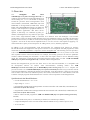
1. Overview
The
Orangutan
SVP
robot
controller [http://www.pololu.com/catalog/product/1325] is a
complete control solution for small and medium-sized
robots running at 6 – 13.5 V. The module is designed
around the powerful Atmel ATmega324PA AVR
microcontroller (32 KB flash, 2 KB RAM, and 1 KB
EEPROM) or ATmega1284P (128 KB flash, 16 KB
RAM, and 4 KB EEPROM) running at 20 MHz and
features a full complement of peripheral hardware to
support robotics applications: dual motor drivers
capable of delivering 2 A continuous (6 peak) per
channel, a demultiplexer for easy control of up to eight
servos with a single hardware PWM, a removable 16×2 character LCD with backlight, a user trimmer
potentiometer, a buzzer for simple sounds and music, three user pushbuttons, and two user LEDs. The board also
provides 21 free I/O lines, of which 12 can be used as analog inputs, and two switching buck (step-down) voltage
regulators—one for the 5V bus and one adjustable from 2.5 V to 85% of VIN—each capable of supplying 3 A,
which means there’s plenty of room and power for adding sensors, servos, and other peripherals.
In addition to the user-programmable AVR microcontroller, the Orangutan SVP features an auxiliary
PIC18F14K50 MCU that supports the main processor and serves as an integrated AVR ISP programmer, which
means that no external programmer is required to use the Orangutan SVP. This auxiliary processor provides a
USB connection that allows direct communication with a PC, and its firmware lets it perform several useful
task in parallel with the main microcontroller. For example, the auxiliary processor can read two quadrature
encoders without burdening the main MCU, or those same four inputs could be used as additional analog
inputs. The ATmega324 or ATmega1284 can read data from the auxiliary MCU over SPI. A USB A to mini-B
cable [http://www.pololu.com/catalog/product/1129] is included with the Orangutan SVP.
Because the Orangutan SVP gives the user direct access to the AVR microcontroller, it is compatible with
all development software for Atmel’s AVR microcontrollers, including Atmel’s free AVR
Studio [http://www.atmel.com/avrstudio/] and the WinAVR [http://winavr.sourceforge.net/] GCC C/C++ compiler. We
provide an extensive set of software libraries [http://www.pololu.com/docs/0J20] that make it easy to interface with all
of the integrated hardware, including the auxiliary microcontroller. Using these libraries, it takes just a few simple
lines of code to write to the LCD, read button presses, drive motors, and control servos. These libraries come with
a number of sample programs that demonstrate how to use the various components on the Orangutan SVP.
Specifications & On-Board Hardware
• Overall unit dimensions: 3.70" × 2.20"
• Input voltage: 6 – 13.5 V
• Programmable 20 MHz Atmel ATmega324PA AVR microcontroller with 32 KB flash, 2 KB SRAM, and
1 KB EEPROM (SVP-324 version)
• Programmable 20 MHz Atmel ATmega1284P AVR microcontroller with 128 KB flash, 16 KB RAM, and
4 KB EEPROM (SVP-1284 version)
• Built-in USB AVR ISP programmer (USB A to mini-B cable [http://www.pololu.com/catalog/product/1129]
included)
• 2 bidirectional motor ports (2 A continuous per channel, 6 A maximum per channel)
• 8-output demultiplexer tied to one of the AVR’s hardware PWMs for easy control of up to 8 servos
• 21 free I/O lines
1. Overview
Page 2 of 41
Pololu Orangutan SVP User's Guide
© 2001–2010 Pololu Corporation
◦ 17 free I/O lines on the main MCU, of which 8 can be analog inputs
◦ 4 input lines on the auxiliary processor, which can be either 4 analog inputs or dual quadrature
encoder inputs
◦ 2 hardware UARTs
• Removable 16-character × 2-line LCD with backlight
• Primary 5V switching regulator capable of supplying 3 A
• Secondary adjustable (2.5 V – 85% of VIN) buck (step-down) voltage regulator capable of supplying 3 A
• Buzzer tied to one of the AVR’s hardware PWMs
• 3 user pushbutton switches
• 2 user LEDs
• Power (push-on/push-off) and reset pushbutton switches
• Power circuit makes it easy to add extra power buttons and provides a self-shutdown option
• Auxiliary processor (connected via SPI) provides:
◦ Battery voltage reading
◦ User trimmer potentiometer reading
◦ Integrated USB connection
◦ In-System-Programming of the main processor
◦ Ability to read two quadrature encoders
Orangutan SVP kit.
Orangutan SVP fully assembled.
For a Spanish version of this document, please see Orangutan SVP Guia de
Usuario [http://www.pololu.com/file/download/OrangutanSVPGuiaUsuario.pdf?file_id=0J328] (1725k pdf)
(provided by customer Jaume B.).
1.a. Supported Operating Systems
The Orangutan SVP’s USB connection works under Microsoft Windows XP, Windows Vista, Windows 7, and
Linux. The Orangutan SVP’s USB connection can be used to program the AVR, communicate directly with the
AVR from a computer, or communicate with TTL-level serial devices from a computer.
1. Overview
Page 3 of 41
Pololu Orangutan SVP User's Guide
© 2001–2010 Pololu Corporation
Under Linux, the three virtual COM ports created by the SVP should appear as devices with names like /dev/
ttyACM0, /dev/ttyACM1, and /dev/ttyACM2 (the numbers depends on how many other ACM devices you have
plugged in) and you can use any terminal program (such as kermit) to send and receive bytes on those ports.
The Orangutan SVP’s USB connection is not compatible with any version of Mac OS.
Note: You may not need to use the Orangutan SVP’s USB connection. If you have an AVR
ISP programmer, then you can program the AVR on the Orangutan SVP by connecting your
programmer to the 6-pin AVR ISP header located near the SVP’s USB connector. In that case, the
operating system of your computer does not matter, as long as your programmer works.
1. Overview
Page 4 of 41
Pololu Orangutan SVP User's Guide
© 2001–2010 Pololu Corporation
2. Contacting Pololu
You can check the Orangutan SVP-324 robot controller page [http://www.pololu.com/catalog/product/1325] or
Orangutan SVP-1284 robot controller page [http://www.pololu.com/catalog/product/1327] for additional information,
including pictures, example code, and application notes. You can also find libraries for interacting with the onboard hardware and an assortment of sample code in the Pololu AVR Library [http://www.pololu.com/docs/0J20].
We would be delighted to hear from you about any of your projects and about your experience with the
Orangutan Robot controllers. You can contact us [http://www.pololu.com/contact] directly or post on our
forum [http://forum.pololu.com/]. Tell us what we did well, what we could improve, what you would like to see in
the future, or anything else you would like to say!
2. Contacting Pololu
Page 5 of 41
Pololu Orangutan SVP User's Guide
© 2001–2010 Pololu Corporation
3. Schematic Diagrams
Schematic diagrams of the Orangutan SVP are available here: Orangutan
diagram [http://www.pololu.com/file/download/org06a02_schematic.pdf?file_id=0J265] (99k pdf)
3. Schematic Diagrams
SVP
schematic
Page 6 of 41
Pololu Orangutan SVP User's Guide
© 2001–2010 Pololu Corporation
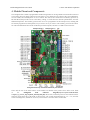
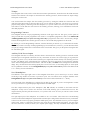
4. Module Pinout and Components
The Orangutan SVP contains a programmable AVR ATmega324PA or ATmega1284P microcontroller connected
to two motor drivers for direct control of two DC motors, a 16×2 character LCD, a buzzer, three user pushbuttons,
two user LEDs, and a demultiplexer for servo control. The AVR is also connected to an auxiliary processor (a
PIC18F14K50) that provides access to the battery voltage, a 10 kilo-ohm user trimmer potentiometer, and four
additional input lines. The auxiliary processor also serves as a programmer for the main processor, meaning that
an external programmer is not required, but you can use one if you want to. The auxiliary processor also allows
for USB communication between the AVR and a personal computer, and acts as a USB-to-serial converter.
Orangutan SVP fully assembled PCB with pins labeled.
These and the rest of the main features of the module are labeled in the picture above and in more detail
in
the
Orangutan
SVP
reference
diagram [http://www.pololu.com/file/download/
orangutan_svp_reference_diagram.pdf?file_id=0J244] (82k pdf). Most of the connection points are also indicated on the
silkscreen on the back side of the PCB, as shown below. The overall unit dimensions are 3.7" × 2.2", and four
0.086" mounting holes, suitable for #2 screws, are located 0.1" from the corners of the board.
4. Module Pinout and Components
Page 7 of 41
Pololu Orangutan SVP User's Guide
© 2001–2010 Pololu Corporation
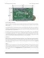
Orangutan SVP-324 with dimensions.
Power & Motor Connections
The power and motor connections are in the lower-right corner of the unit. The Orangutan SVP’s input voltage
(VBAT) should be 6 – 13.5 V, from which the on-board regulator generates the 5 V supply (VCC) that is used to
power the logic.
The Orangutan SVP has one TB6612FNG motor driver for each motor output. Each motor driver can deliver a
continuous 2 A, and can briefly deliver up to 6 A. If you are not taking extra steps to keep the motor driver cool,
such as using a heat sink, exceeding this continuous current rating for too long will cause the motor driver to heat
up and trigger its built-in thermal shutdown.
By default, the motor drivers are powered from the external power supply (VBAT). However, you can disconnect
the external power supply from the motor drivers by cutting the labeled traces on the bottom of the board (VBATVM1 and VBAT-VM2). This allows you to connect some other power supply to the motor drivers, such as VADJ
(see below). The motor drivers have an operating range of 4.5 – 13.5 V, so your power supply should be in that
range, and should be capable of supplying all the current that your motors might draw.
USB Power
When connected to a computer, the USB connection provides a 5 V power supply. If an external power supply is
present, the unit will run off of the external supply and not draw any power from USB. If only the USB power is
present, then by default the auxiliary processor will be powered from USB, but the AVR and the VCC power pins
on the board will not be powered. An option is available for powering the entire board from USB. See Section 11
for more information.
Motors
The motor drivers are controlled by two of the AVR’s hardware PWM outputs from eight-bit Timer2 for speed
control, along with two digital outputs for direction control. This lets you achieve variable motor speeds using
hardware PWMs rather than processor-intensive software PWMs on the motor control lines. You can control the
motors using the functions in the OrangutanMotors [http://www.pololu.com/docs/0J18/7] section of the Pololu AVR
C/C++ Library.
4. Module Pinout and Components
Page 8 of 41
Pololu Orangutan SVP User's Guide
© 2001–2010 Pololu Corporation
For each motor, the Orangutan SVP has a current-sensing circuit that produces an output voltage proportional to
the current the motors are using (850 mV/A). The respective outputs of these circuits are labeled CS1 and CS2,
and they are accessible near the center of the board.
User I/O & Power Outputs
Sixteen user I/O lines can be accessed via the four 4×3 0.100" female headers along the lower edger of the board,
as shown below. Each I/O line has associated power and ground connections for easy connections to sensors: the
exterior (bottom) pin is ground, the middle pin is power, and the interior (top) pin is signal and connects directly
to an AVR I/O line.
For each four-pin bank of I/O lines, you can configure which power voltage is supplied to the power (middle)
pins. By default, the power pins are connected to VCC (5 V). You can cut a trace on the bottom of the board
to disconnect them from VCC. This will leave the power pins connected to one through-hole, which can be
connected to a different power source, such as VBAT, which is available elsewhere on the board.
The total current available on the VCC (5 V) line is 3 A, meaning you can power servos and other high-power
peripherals directly from your regulated voltage.
LCD
The Orangutan SVP is supplied with a removable 16×2 character LCD with backlight that uses the common
HD44780 parallel interface [http://www.pololu.com/file/download/DMC50448N-AAE-AD.pdf?file_id=0J71] (109k pdf). A
different LCD can be connected with an appropriate cable. The AVR has four I/O lines connected to LCD data
lines DB4 – DB7 (i.e. is configured to use the LCD in 4-bit mode) and three I/O lines connected to the three LCD
control lines RS, R/W, and E. Please note that the LCD data lines are also shared by the user pushbuttons and the
green user LED. You can print to the LCD using the functions in the OrangutanLCD [http://www.pololu.com/docs/
0J18/5] section of the Pololu AVR C/C++ Library.
The LCD’s backlight can be turned off by driving the BACKLIGHT line low. Adjustable dimming of the LCD
can be achieved by connecting the line to a free PWM output.
The AVR’s AREF pin is available next to the backlight pin.
Pushbuttons
The Orangutan SVP has five total pushbuttons: a power on/off button located on the right side of the bottom
edge of the board, a reset button located on the left side of the top edge of the board, and three user pushbuttons
located along the left edge of the board. Please note that the power button disconnects the external power supply
from the entire board, while the reset button connects directly to the AVR’s RESET pin and does not disconnect
the power supply.
The user pushbuttons, from top to bottom, are on pins PC5, PC3, and PC2. Pressing one of these buttons pulls
the associated I/O pin to ground through a resistor. You can detect button pushes using the functions in the
OrangutanPushbuttons [http://www.pololu.com/docs/0J18/9] section of the Pololu AVR C/C++ Library. The library
takes care of configuring the pins as inputs, enabling the AVR’s internal pull-up resistors, and debouncing
(accounting for the fact that pushbuttons physically bounce when pressed).
Buzzer
The Orangutan SVP comes with a buzzer controlled by pin PD4. If you alternate between driving the buzzer pin
high and low at a given frequency, the buzzer will produce sound at that frequency. You can use the functions in
the OrangutanBuzzer [http://www.pololu.com/docs/0J18/3] section of the Pololu AVR C/C++ Library to play notes in
the background (using hardware PWM) while the rest of your processor performs other tasks.
4. Module Pinout and Components
Page 9 of 41
Pololu Orangutan SVP User's Guide
© 2001–2010 Pololu Corporation
Trimpot
The Orangutan SVP comes with a 10 kilo-ohm user trimmer potentiometer, located between the USB connector
and the LCD connector. The trimpot is connected to the auxiliary processor, which measures its output voltage
and reports it to the AVR.
You can disconnect the trimpot from the auxiliary processor by cutting the labeled trace between POT and
ADC/SS on the bottom side of the board. This gives you two options for that line: you can use it as a generalpurpose analog input by connecting some other output to it, or you can connect it to one of your AVR’s free I/O
lines and use it as the SPI slave-select line for the auxiliary processor, allowing you to communicate with some
other SPI peripheral.
Programming Connector
The Orangutan SVP has a 6-pin programming connector on the upper left side. This gives you the option of
using an AVR ISP in-system programmer from Atmel or a compatible programmer, such as our Pololu USB
AVR Programmer [http://www.pololu.com/catalog/product/1300] to program the AVR. This is not necessary, though,
because the Orangutan SVP’s auxiliary processor can serve as an AVR ISP programmer for the AVR.
By default, pin 5 of the Programming connector, which is labeled by an asterisk (*), is connected to the AVR’s
RESET line, which is necessary for ISP programming by an external device). However, you can disconnect those
two pins by cutting a labeled trace on the bottom of the circuit board. This gives you the option of using that line
for some other signal.
Auxiliary I/O & Power Outputs
The Orangutan SVP has five auxiliary I/O lines that are connected to the auxiliary processor. Each I/O line has
associated power and ground connections for easy connections to sensors: the exterior (top) pin is ground, the
middle pin is power (VCC), and the interior (bottom) pin is signal and connects directly to an auxiliary processor
I/O line. The TX line is the serial transmit line. It transmits TTL-level serial bytes received from the computer
on the “Pololu Orangutan SVP TTL Serial Port”. The lines A, B, C, and D/RX can be configured to do different
things. They can function as three analog inputs plus a serial receive line, as four analog inputs, or as the inputs
for two quadrature encoders. See the OrangutanSVP [http://www.pololu.com/docs/0J18/13] section of the Pololu AVR
C/C++ Library for more information.
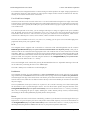
Servo Demultiplexer
The hardware in the upper-right corner of the Orangutan SVP allows you to control up to 8 servos without
sacrificing a large number of I/O lines or processor cycles. You can control servos using the functions in the
OrangutanServos [http://www.pololu.com/docs/0J18/11] section of the Pololu USB AVR C/C++ library.
The input signal of the demultiplexer is connected to pin PD5 on the AVR. If you are not using PD5 to control
servos, you can use it as a general-purpose digital I/O line or PWM output.
The three output-selection pins of the multiplexer (SA, SB, and SC) are available in the header near the
multiplexer so they can be wired to free I/O lines on the AVR, allowing you to switch between servos. The
output-selection pins have pull-down resistors, so if you have four servos or fewer you can leave some of them
disconnected.
The eight output pins of the multiplexer are available in two 4×3 headers. These lines have current-limiting
resistors on them. Each multiplexer output line has associated power and ground connections for easy connections
to the servos: the exterior (top) pin is ground, the middle pin is power. For each bank of servos, you can configure
which power supply is connected to the power pins, using the provided headers and jumpers. You can power
the servos from VCC, VADJ (see below), or a separate power supply. The fully assembled version ships with a
4. Module Pinout and Components
Page 10 of 41
Pololu Orangutan SVP User's Guide
© 2001–2010 Pololu Corporation
jumper attached to just the middle pin of each of the two servo power selection banks. In this default orientation,
the jumper supplies no power to the servo power rail.
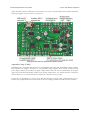
Orangutan SVP with key integrated hardware labeled.
Adjustable Voltage (VADJ)
In addition to the 5 V regulator that supplies VCC, the Orangutan SVP comes with an adjustable voltage regulator.
Both regulators can supply a current of 3 A. The adjustable voltage regulator draws current from the external
power supply (VBAT), and produces an output voltage called VADJ. The trimmer potentiometer in the upper
right corner of the board determines VADJ. If you turn the trimpot all the way counter-clockwise, VADJ goes
down to about 2.5 V. If you turn it all the way clockwise, VADJ rises to 85% of VIN.
In general, it is advantageous to power servos and other high-power devices from VADJ (instead of VCC),
because if the peripherals draw too much current for the power supply to handle the AVR will not be affected.
4. Module Pinout and Components
Page 11 of 41
Pololu Orangutan SVP User's Guide
© 2001–2010 Pololu Corporation
LEDs
Orangutan SVP LEDs.
The Orangutan SVP comes with 9 LEDs:
• A blue power LED is located next to the power button.
• There are four motor indicator LEDs located near the motor outputs. A green LED lit indicates that the
corresponding motor is being driven “forward” (the voltage on output B is higher than the voltage on A).
A red LED indicates that the corresponding motor is being driven in “reverse” (the voltage on output B is
lower than the voltage on output A).
• A red user LED is located near the AVR I/O banks. The LED is connected to the user I/O line PD1. It will
light if you set PD1 as a low output. Since PD1 is the serial transmit line for UART0 (TXD0), the LED will
flicker whenever serial data is being transmitted from the AVR. The LED can be disconnected from PD1 by
cutting a labeled trace (PD1-LED) on the bottom of the board.
• A green user LED is located between the trimpot and the buzzer. It will light if you set PC4 as a high
output. Note that PC4 is also used as an LCD data line, so you will see the green LED flicker when you
update the LCD.
• Another green LED is located near the USB connector. This LED is controlled by the auxiliary processor
and indicates the status of the USB connection. When the USB is disconnected, or the device is in the USB
Suspend state (because the computer went to sleep), the green LED is off. When you connect the device to
a computer via USB, the green LED will start blinking slowly. The blinking continues until it receives a
particular message from the computer indicating that the drivers are installed correctly. After the programmer
gets this message, the green LED will be on, but it will flicker briefly when there is USB activity.
• Another red LED is located near the header for the auxiliary processor’s TX line. This LED is tied to
the TX line, so it will flicker whenever the auxiliary processor is transmitting TTL-level serial bytes from
the computer. This LED will also blink when the auxiliary processor powers up to indicate bad startup
conditions. Two blinks indicates that a brown-out reset was triggered: the processor’s VDD dropped below
4. Module Pinout and Components
Page 12 of 41
Pololu Orangutan SVP User's Guide
© 2001–2010 Pololu Corporation
3.0 V. If this happens to you, check your power connections and battery voltage, and make sure you are not
drawing too much power from the board.
4. Module Pinout and Components
Page 13 of 41
Pololu Orangutan SVP User's Guide
© 2001–2010 Pololu Corporation
5. Getting Started
5.a. Installing Windows Drivers
If you use Windows XP, you will need to have either Service Pack 3 [http://www.microsoft.com/
downloads/details.aspx?FamilyId=68C48DAD-BC34-40BE-8D85-6BB4F56F5110]
or
Hotfix KB918365 [http://support.microsoft.com/kb/918365] installed before installing the drivers for the
Orangutan SVP.
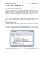
Before you connect your Pololu Orangutan SVP robot controller to a computer running Microsoft Windows, you
must install its drivers:
1. Download
the
Pololu
USB-to-serial
(4k inf)
driver
for
Windows [http://www.pololu.com/file/download/
pololu_usb_to_serial.inf?file_id=0J234]
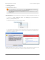
2. Right click on pololu_usb_to_serial.inf and select “Install”.
4. After selecting “Install”, Windows will warn you that the driver has not been tested by Microsoft and
recommend that you stop the installation. Click “Continue Anyway” (Windows XP) or “Install this driver
software anyway” (Windows Vista).
Windows Vista users: After the INF file is installed, your computer should automatically install the necessary
drivers when you connect an Orangutan SVP, in which case no further action from you is required.
5. Getting Started
Page 14 of 41
Pololu Orangutan SVP User's Guide
© 2001–2010 Pololu Corporation
Windows XP users: After the INF file is installed, follow steps 5-9 for each new Orangutan SVP you connect to
your computer.
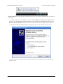
5. Connect the device to your computer’s USB port. The Orangutan SVP shows up as three devices
in one so your XP computer will detect all three of those new devices and display the “Found New
Hardware Wizard” three times. Each time the “Found New Hardware Wizard” pops up, follow steps 6-9.
6. When the “Found New Hardware Wizard” is displayed, select “No, not this time” and click “Next”.
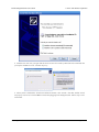
7. On the second screen of the “Found New Hardware Wizard”, select “Install the software automatically”
and click “Next”.
5. Getting Started
Page 15 of 41
Pololu Orangutan SVP User's Guide
© 2001–2010 Pololu Corporation
8. Windows XP will warn you again that the driver has not been tested by Microsoft and recommend that
you stop the installation. Click “Continue Anyway”.
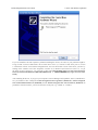
9. When you have finished the “Found New Hardware Wizard”, click “Finish”. After that, another wizard
will pop up. You will see a total of three wizards when plugging in the Orangutan SVP. Follow steps 6-9 for
each wizard.
5. Getting Started
Page 16 of 41
Pololu Orangutan SVP User's Guide
© 2001–2010 Pololu Corporation
If you use Windows XP and experience problems installing the drivers, the cause of your problems might be
a bug in older versions of Microsoft’s usb-to-serial driver usbser.sys. Versions of this driver prior to version
5.1.2600.2930 will not work with the Orangutan SVP. You can check what version of this driver you have by
looking in the “Details” tab of the “Properties” window for C:\Windows\System32\drivers\usbser.sys. To get
the fixed version of the driver, you will need to either install Service Pack 3 [http://www.microsoft.com/downloads/
details.aspx?FamilyId=68C48DAD-BC34-40BE-8D85-6BB4F56F5110] or Hotfix KB918365 [http://support.microsoft.com/kb/
918365].
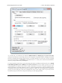
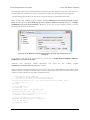
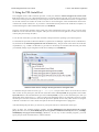
After installing the drivers, if you go to your computer’s Device Manager and expand the “Ports (COM & LPT)”
list, you should see three COM ports: Pololu Orangutan SVP Programmer (Section 5.c), Pololu Orangutan
SVP USB Communication Port (Section 8), and the Pololu Orangutan SVP TTL Serial Port (Section 9). In
parentheses after these names, you will see the name of the port (e.g. “COM5” or “COM6”).
5. Getting Started
Page 17 of 41
Pololu Orangutan SVP User's Guide
© 2001–2010 Pololu Corporation
Windows XP device manager showing the Pololu Orangutan
SVP.
Windows Vista device manager showing the Pololu Orangutan SVP.
Some software will not allow connection to higher COM port numbers. For example, AVR Studio can only
connect to COM1 through COM9. If you need to change the COM port number assigned to one of the COM
ports, you can do so using the Device Manager. Bring up the properties dialog for the COM port and click the
“Advanced…” button in the “Port Settings” tab. From this dialog you can change the COM port assigned to your
device.
5.b. Using the Demo Program
The Demo Program
The Orangutan ships with a demo program pre-loaded which demonstrates most of its features and allows you to
test that it is working correctly. When you first turn on your Orangutan, you should see the red user LED blinking
about once per second. If you have soldered a buzzer in to your SVP (or bought the assembled version), you will
also hear a beep. If you have connected an LCD, you will see the words “Pololu Orangutan SVP”, then “Demo
Program” appear, indicating that you are running the demo program. If you see the blinking red LED but do not
see any text on the LCD, you may need to adjust the contrast potentiometer in the lower left corner of the board.
When the program has started successfully, press the Middle Button button (marked PC3 on the underside of the
5. Getting Started
Page 18 of 41
Pololu Orangutan SVP User's Guide
© 2001–2010 Pololu Corporation
board) to proceed to the main menu. Press the Top Button (marked PC5) or the Bottom Button (marked PC2) to
scroll forward or backward through the menu, and press the Middle Button to make a selection or to exit one of
the demos. There are nine demos accessible from the menu:
1. Analog Inputs: This demo displays voltage readings from the Orangutan SVP’s 13 analog inputs as a
bar graph. The inputs are in this order: PA7, PA6, PA5, PA4, PA3, PA2, PA1, PA0, trimpot, A, B, C, D. You
can press the top button to enable/disable the pull-up resistors on PA0—PA7.
2. Battery Voltage: This demo displays the battery voltage in millivolts.
3. Digital Inputs: This demo displays the digital readings from some of the user-accessible digital input
lines. The pull-up resistors are enabled, so each line should read 1 if they are not connected to anything. If
you connect a wire between one of these lines and ground, you should see its reading go to zero (be careful
not to cause a short circuit).
4. LEDs: Blinks the red and green user LEDs.
5. Trimpot: Displays the position of the user trimmer potentiometer, which is located in the upper left
corner of the board, as a number between 0 and 1023. While displaying the value, this demo also blinks the
LEDs and plays a note whose frequency is a function of the current reading. It is easiest to turn the trimpot
using a 2 mm flat-head screwdriver.
6. Motors: Hold down the bottom or top buttons to run motors 1 or 2, respectively, or hold down
both buttons to run both motors simultaneously. The motors will gradually ramp up to speed; in your
own programs, you can switch them on much more suddenly. Tap the bottom or top buttons to switch
the corresponding motor to reverse (the button name becomes lowercase if pressing it will drive the
corresponding motor in reverse).
7. Music: Plays a song while scrolling a text display. This demonstrates the ability of the Orangutan to play
music in the background.
8. Timer: A simple stopwatch. Press the bottom button to start or stop the stopwatch and the top button to
reset. The stopwatch continues to count while you are exploring the other demos.
9. USB: Demonstrates the USB connection between the Orangutan SVP and a computer. Plug the
Orangutan SVP in to USB. Any bytes you send on the Pololu Orangutan SVP USB Communications Port
(Section 8) will be displayed on the screen, and echoed back to the computer so you can see them in your
terminal program. The red LED indicates the state of the DTR handshaking line, and the green LED indicates
the state of the RTS handshaking line.
The source code for the demo program is included with the Pololu AVR C/C++
Library [http://www.pololu.com/docs/0J20]. After downloading and unpacking the library zip file, the demo program
can be found in the examples\atmega324p\svp-demo-program or examples\atmega1284p\svp-demo-program
directory, depending on whether you have the SVP-324 or SVP-1284.
5.c. Programming in Windows with AVR Studio
To program your Orangutan SVP’s on-board ATmega324P or ATmega1284PA microcontroller in Windows, we
recommend you download and install the following:
• WinAVR [http://winavr.sourceforge.net/]. WinAVR is a free, open-source suite of development tools for the
AVR family of microcontrollers, including the GNU C/C++ compiler for AVRs (avr-gcc). Please follow the
installation instructions on WinAVR’s website.
• AVR Studio [http://www.atmel.com/avrstudio/]: AVR Studio is a free integrated development environment
(IDE) for programming AVRs offered by Atmel. AVR Studio works with the WinAVR avr-gcc compiler
and contains built-in support for AVR ISP programming. Please follow Atmel’s installation instructions for
AVR Studio.
5. Getting Started
Page 19 of 41
Pololu Orangutan SVP User's Guide
© 2001–2010 Pololu Corporation
As a first step, we recommend you try to program your Orangutan with a simple program that blinks the red user
LED on pin PD1. Download the file below that corresponds to your particular Orangutan SVP model:
• Orangutan
SVP-324:
(7k zip)
BlinkLED_m324.zip [http://www.pololu.com/file/download/
BlinkLED_m324.zip?file_id=0J235]
• Orangutan
SVP-1284:
BlinkLED_m1284.zip?file_id=0J326] (8k zip)
BlinkLED_m1284p.zip [http://www.pololu.com/file/download/
Open the AVR Studio Project by double clicking on BlinkLED.aps. Connect your Orangutan SVP to USB. In
the Tools menu, select Program AVR > Connect…. Select the AVRISP platform. Select the COM port of the
“Pololu Orangutan SVP Programmer” port as seen in your Device Manager in the “Ports (COM & LPT)” list.
Since AVR Studio only supports connecting to COM1 through COM9, you may need to change your port number
in the device manager. Click the Connect… button. If AVR Studio successfully connects to the Orangutan SVP’s
programmer, it should bring up an STK500 dialog box. Under the Main tab of this new dialog box, select
ATmega324PA or ATmega1284P depending on which SVP model you have. In the Flash section of the Program
tab, navigate to the project’s hex file (which is created in the default directory when you build the project).
Make sure that the Orangutan SVP’s AVR is powered (the blue LED must be on). Now click the Program flash
button. If everything has worked correctly, you should see the Orangutan’s red user LED blinking around once
per second.
5. Getting Started
Page 20 of 41
Pololu Orangutan SVP User's Guide
© 2001–2010 Pololu Corporation
As a second step, we recommend you install the Pololu AVR C/C++ Library [http://www.pololu.com/docs/0J20],
which provides functions for interacting with all of the Orangutan’s integrated hardware, including the auxiliary
processor, and many demo programs that show how to use these functions. For an overview of how to program
your SVP using the library, see Section 6.j of the Pololu AVR C/C++ Library User’s Guide. This should make it
easier for you to get started with your Orangutan.
For a more detailed account of how to get started using AVR Studio, including screenshots, please see our Pololu
USB AVR Programmer User’s Guide [http://www.pololu.com/docs/0J36]. The user’s guide is specific to our USB
AVR programmer, but much of the section on using AVR Studio is relevant to using the Orangutan SVP’s
built-in programmer. One notable difference, however, is that the Orangutan SVP’s built-in programmer ignores
AVR Studio’s ISP frequency parameter and always programs at 2 MHz. Also, the Orangutan SVP’s programmer
prevents you from setting any of the fuses controlling the AVR’s clock settings. This is to prevent you from
accidentally using an invalid clock setting and rendering your AVR unprogrammable.
5. Getting Started
Page 21 of 41
Pololu Orangutan SVP User's Guide
© 2001–2010 Pololu Corporation
5.d. Programming in Linux or Windows using AVRDUDE
AVRDUDE [http://savannah.nongnu.org/projects/avrdude/] is a free program for Windows and Linux that allows
you to program your Orangutan SVP’s on-board ATmega324PA or ATmega1284P microcontroller. You can
compile an Intel Hex (.hex) file using avr-gcc, and then program the hex file on to your Orangutan SVP using
AVRDUDE. AVRDUDE accomplishes this by sending serial commands to the Orangutan SVP’s built-in AVR
ISP programmer.
Linux users can get AVRDUDE by installing the avrdude package. You will also need to install these packages:
• gcc-avr: the GNU C compiler, ported to the AVR architecture
• avr-libc: a library giving access to special functions of the AVR
• binutils-avr: tools for converting object code into hex files
These packages can be downloaded from their respective websites. Under Ubuntu Linux, these packages are
provided in the “Universe” repository and can be installed with apt-get.
Windows users can get AVRDUDE as part of the WinAVR [http://winavr.sourceforge.net/] package (which also
includes avr-gcc and other utilities you will need for programming AVRs). Note that most Windows users do not
use AVRDUDE because AVR Studio has its own built-in AVR ISP programming software which can be more
convenient.
AVRDUDE does not yet support the ATmega324PA. If you have an SVP-324, you should use the
option to specify the ATmega324P and the -F to override the device signature check.
-p m324p
AVRDUDE has incorrect chip erase delay settings for the ATmega324P and ATmega1284P. This means that
when you try to erase the flash on your AVR (which is the first step whenever you are loading a new program), the
erase operation will take longer than AVRDUDE expects and AVRDUDE will interpret this as an error. This error
causes problems in the latest version of AVRDUDE (version 5.10 which is included with WinAVR-20100110)
because that version will not attempt to program flash if the erase step has failed.
There are three alternative workarounds to this problem:
Option 1 (recommended): In the AVRDUDE configuration file, avrdude.conf, change the chip erase delay for
the m1284p and m324p both to 55000. The file is located in C:\WinAVR-20100110\bin\ in Windows or /etc/ in
Linux.
Option 2: Use AVRDUDE version 5.6 (which is included in WinAVR-20090313). This version works fine for
the ATmega324p and ATmega1284p despite the incorrect chip erase delay in avrdude.conf, because it was
programmed to continue with the flash programming even if the chip erase operation timed out. (AVRDUDE
versions 5.7, 5.8, and 5.9 might work also but we have not tested them.)
Option 3: Whenever you want to program flash with AVRDUDE, first issue a command with the -e option to
erase the chip, and then issue a command to program the flash which uses the -D option so AVRDUDE does not
try to erase the chip again. The first command will time out and print an error message but nevertheless succeed
in erasing the chip.
We have several example projects that will let you get started compiling programs using avr-gcc and load them
on to the SVP using AVRDUDE. As a first step, we recommend you try to program your Orangutan with a simple
program that blinks the red user LED on pin PD1. Download the file below that corresponds to your particular
Orangutan SVP model:
5. Getting Started
Page 22 of 41
Pololu Orangutan SVP User's Guide
• Orangutan
© 2001–2010 Pololu Corporation
SVP-324:
(7k zip)
BlinkLED_m324.zip [http://www.pololu.com/file/download/
BlinkLED_m324.zip?file_id=0J235]
• Orangutan
SVP-1284:
BlinkLED_m1284.zip?file_id=0J326] (8k zip)
BlinkLED_m1284p.zip [http://www.pololu.com/file/download/
You can move the Makefile from linux/ in to the top directory and compile using the make command. This should
generate a file BlinkLED.hex which you can program on to your SVP by running avrdude.
• For the Orangutan SVP-324: avrdude
• For the Orangutan SVP-1284: avrdude
-c avrisp2 -U flash:w:BlinkLED.hex -p m1284p -P [PORT]
-c avrisp2 -U flash:w:BlinkLED.hex -p m324p -F -P [PORT]
In the commands above, you should change [PORT] to be the serial port name of the Orangutan SVP’s
programmer. In Linux, this will usually be /dev/ttyACM0 (depending on how many other CDC ACM devices you
have) but you can also check dmesg. In Windows, look in your Device Manager for an entry that says “Pololu
Orangutan SVP Programmer”. If the COM number is greater than 9 (e.g. COM10) then you may need to put \\.\
before it (e.g. -P \\.\COM10). In Windows, -P \\.\USBSER000 will usually work as well.
As a second step, we recommend you install the Pololu AVR C/C++ Library [http://www.pololu.com/docs/0J20],
which provides functions for interacting with all of the Orangutan’s integrated hardware, including the auxiliary
processor, and many demo programs that show how to use these functions. For an overview of how to program
your SVP using the library, see Section 6.j of the Pololu AVR C/C++ Library User’s Guide. This should make it
easier for you to get started with your Orangutan.
5.e. Assembling the kit version
This section is a guide to the connection points where you will likely want to solder hardware on to the kit version
of the Orangutan SVP.
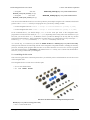
The Orangutan SVP kit version comes with these parts:
• Six 3×4 male header blocks
• Six
3×4
female
header
Hardware included with the Orangutan SVP partial kit.
blocks [http://www.pololu.com/catalog/product/1034]
• One 3×7 male header block
5. Getting Started
Page 23 of 41
Pololu Orangutan SVP User's Guide
© 2001–2010 Pololu Corporation
• One 3×7 female header block
• Three 2-pin 3.5mm terminal blocks
• Five blue shorting blocks [http://www.pololu.com/catalog/product/968]
• Two 2×3 female header blocks [http://www.pololu.com/catalog/product/1023]
• One 2×3 shrouded box header [http://www.pololu.com/catalog/product/854]
• One 2×8 shrouded box header [http://www.pololu.com/catalog/product/898]
• One buzzer
• Five pushbuttons [http://www.pololu.com/catalog/product/1400]
• One 2×20 breakaway male header [http://www.pololu.com/catalog/product/966]
• One 1×20 breakaway male header [http://www.pololu.com/catalog/product/965]
• Five 1×2 female header blocks [http://www.pololu.com/catalog/product/1012]
• Two single-pin female headers
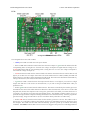
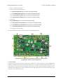
The labeled photo below shows possible locations for installing these parts:
Orangutan SVP kit PCB showing possible locations for included buzzer,
pushbuttons, headers, and terminal blocks.
1. Power button
To turn on your the AVR, you need to connect a power button (or a jumper at location 11). The Orangutan SVP
PCB has two parallel sets of holes for the power button. You can solder a pushbutton between the wider set of
holes, and/or you can make your own connection to the narrower of holes using an included 1×2 header or direct
soldering. If the Orangutan is not easily accessible inside your robot, this allows you to install a momentary power
switch in a more convenient location.
5. Getting Started
Page 24 of 41
Pololu Orangutan SVP User's Guide
© 2001–2010 Pololu Corporation
2. Power input
There are two parallel connection points provided for the 6–13.5V power input. You can install a 3.5mm terminal
block on the large holes to accommodate large wires. You can also install a 1×2 male header on the smaller holes
and plug a battery pack [http://www.pololu.com/catalog/category/54] directly in to it.
3. Motor outputs
You can install two 3.5mm terminal blocks to accommodate your motor leads.
4. User I/O blocks
The AVR user I/O pins are divided in to four blocks. The kit comes with enough 3×4 headers so that you can
choose for each block whether to make its pins female or male. You can also mix the genders together within one
block using the other included headers.
5. Backlight and AREF header
If you want to be able to turn your LCD’s backlight off or use an external voltage reference source, you may want
to solder a 1×2 header on to this location.
6. LCD connector
The pins in the LCD connector area are arranged so that the AVR can control an LCD using the standard 4-bit
HD44780 protocol and optionally power an LCD backlight. On the assembled (non-kit) version of the Orangutan
SVP, we solder a 2×8 shrouded header in to the 16 pins highlighted in the diagram. Then the 16×2 character
LCD with backlight [http://www.pololu.com/catalog/product/772] (included with the assembled version, but not the
kit version) plugs in to the lower 7 rows of the connector, as well as the A and K lines on the other side
of the board. If you have a different kind of LCD, consult its datasheet and the Orangutan SVP Reference
Diagram [http://www.pololu.com/file/download/orangutan_svp_reference_diagram.pdf?file_id=0J244] (82k pdf) to determine
the correct way to connect it.
7. User pushbuttons
The three user pushbuttons can be soldered in at this location.
8. Buzzer
The buzzer can be soldered in at this location.
9. Reset buttons.
A reset pushbutton can be soldered in at this location.
10. SPI/Programming connector
The assembled version comes with a 2×3 shrouded box header soldered in to this location (with the notch pointing
away from the USB connector). This allows you to use an external AVR ISP programmer to program the AVR if
you don’t want to use the integrated programmer for whatever reason. It also provides access to the AVR’s SPI
pins, so you could use this location to connect an SPI device to your Orangutan. A 2×3 female header is provided
for this location.
11. VCC-VUSB jumper
To power the board from USB, install a 1×2 male header at this location and use a blue shorting block to connect
VUSB to VCC. See Section 11 for more information and caveats about using this jumper.
5. Getting Started
Page 25 of 41
Pololu Orangutan SVP User's Guide
© 2001–2010 Pololu Corporation
12. Auxiliary processor I/O block
This block contains the auxiliary processor’s A, B, C, D/RX, and TX lines, as well as several connections to GND
and VCC. You can solder in either the 3×7 male or 3×7 female headers here, or mix and match genders using the
other provided headers.
13. Current sense outputs
If you want access to the analog voltage output of the current-sensing circuitry for each of the motor drivers, you
can solder a 1×2 female header here.
14. Servo demultiplexer block
To access the servo demultiplexer inputs, you can solder a 2×3 female or male header here.
15. Servo outputs
Most servo cables have female ends, so we recommend soldering 3×4 male headers in to the two servo output
blocks. However, if you want to use the demux for something other than servos, the kits has 3×4 female headers
you can use instead.
16. Servo power selection
To use your servo ports, you will need to connect a power source (no power source is connected by default). You
can install two 1×3 male headers at this location and use two shorting blocks to select either VCC or VADJ for
servo power.
17. LCD backlight connection and structural support
If you choose to mount a 16×2 LCD on the Orangutan SVP as is done in the assembled version, you will want to
solder in the two single-pin female headers at this location. This prevents the LCD from tipping down on to the
board and also powers the backlight (if your LCD has one).
5. Getting Started
Page 26 of 41
Pololu Orangutan SVP User's Guide
© 2001–2010 Pololu Corporation
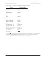
6. AVR Pin Assignment Table Sorted by Function
Function
ATmega324/1284 Pin
free analog input and digital I/O (x8)
PA0 – PA7
free digital I/O (x8)
PB3, PC0, PC1, PD0 – PD4, PD5**
free digital output
PB4*
free PWM outputs (x2)
PB3, PB4
red user LED
PD1
green user LED
PC4
UART0
PD0, PD1
UART1
PD2, PD3
user pushbuttons (bottom to top, x3)
PC2, PC3, PC5
motor 1 (direction, speed)
PC7, PD7
motor 2 (direction, speed)
PC6, PD6
buzzer
PD4
LCD control (RS, R/W, E)
PB0, PB1, PB2
LCD data (4-bit: DB4 – DB7)
PC2 – PC5
SPI auxiliary processor control lines (x3) PB5, PB6, PB7
ICSP programming lines (x3)
PB5, PB6, PB7
ADC reference pin
AREF
reset pushbutton
RESET
*: Using PB4/SS as an input will interfere with communication to the auxiliary processor, so we recommend using
it as a digital output. See Section 6.j of the Pololu USB AVR C/C++ User’s Guide for more information.
**: PD5 is a free digital I/O unless you want to use the built-in servo pulse hardware.
6. AVR Pin Assignment Table Sorted by Function
Page 27 of 41
Pololu Orangutan SVP User's Guide
© 2001–2010 Pololu Corporation
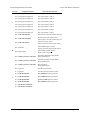
7. AVR Pin Assignment Table Sorted by Pin
7. AVR Pin Assignment Table Sorted by Pin
Page 28 of 41
Pololu Orangutan SVP User's Guide
Port Pin
A
B
C
Orangutan Function
© 2001–2010 Pololu Corporation
Notes/Alternate Functions
PA0 analog input and digital I/O
ADC input channel 0 (ADC0)
PA1 analog input and digital I/O
ADC input channel 1 (ADC1)
PA2 analog input and digital I/O
ADC input channel 2 (ADC2)
PA3 analog input and digital I/O
ADC input channel 3 (ADC3)
PA4 analog input and digital I/O
ADC input channel 4 (ADC4)
PA5 analog input and digital I/O
ADC input channel 5 (ADC5)
PA6 analog input and digital I/O
ADC input channel 6 (ADC6)
PA7 analog input and digital I/O
ADC input channel 7 (ADC7)
PB0 LCD control line RS
Timer/Counter 0 External Counter Input (T0)
PB1 LCD control line R/W
Divided system clock output (CLKO)
Timer/Counter 1 External Counter Input (T1)
PB2 LCD control line E
External interrupt 2 (INT2)
Analog Comparator Positive Input (AIN0)
PB3 digital I/O
Timer0 PWM output A (OC0A)
Analog Comparator Negative Input (AIN1)
PB4 digital output*
Timer0 PWM output B (OC0B)
SPI Slave Select Input (SS)
PB5 auxiliary processor control line
SPI Master Output/Slave Input (MOSI)
ISP programming line
PB6 auxiliary processor control line
SPI Master Input/Slave Output (MISO)
ISP programming line
PB7 auxiliary processor control line
SPI Clock (SCK)
ISP programming line
PC0 digital I/O
I2C/TWI clock line (SCL)
PC1 digital I/O
I2C/TWI input/output data line (SDA)
PC2 LCD data line DB4
user pushbutton (pressing pulls low)
PC3 LCD data line DB5
user pushbutton (pressing pulls low)
PC4 LCD data line DB6
green user LED (high turns LED on)
PC5 LCD data line DB7
user pushbutton (pressing pulls low)
PC6 M2 direction control line
PC7 M1 direction control line
7. AVR Pin Assignment Table Sorted by Pin
Page 29 of 41
Pololu Orangutan SVP User's Guide
D
© 2001–2010 Pololu Corporation
PD0 digital I/O
USART0 input pin (RXD0)
PD1 digital I/O
red user LED
(low turns LED on; connection
can be cut and replaced with jumper)
USART0 output pin (TXD0)
PD2 digital I/O
USART1 input pin (RXD1)
External interrupt 0 (INT0)
PD3 digital I/O
USART1 output pin (TXD1)
External interrupt 1 (INT1)
PD4 buzzer
Timer1 PWM output B (OC1B)
PD5 digital I/O
servo pulse output (SPWM)
Timer1 PWM output A (OC1A)
PD6 M2 speed control line
Timer2 PWM output B (OC2B)
PD7 M1 speed control line
Timer2 PWM output A (OC2A)
AREF
ADC reference pin
AVCC
supply voltage for Port A and ADC not accessible to the user
RESET
Reset input
reset button (pressing resets MCU)
XTAL1
20 MHz resonator input
not accessible to the user
XTAL2
20 MHz resonator input
not accessible to the user
*: Using PB4/SS as an input will interfere with communication to the auxiliary processor, so we recommend using
it as a digital output. See Section 6.j of the Pololu USB AVR C/C++ User’s Guide for more information.
7. AVR Pin Assignment Table Sorted by Pin
Page 30 of 41
Pololu Orangutan SVP User's Guide
© 2001–2010 Pololu Corporation
8. Using the USB Communication Port
The Orangutan SVP’s USB Connection provides a virtual serial port called the Pololu Orangutan SVP USB
Communication Port which allows two-way communication between a personal computer and the Orangutan
SVP’s AVR at a rate of over 20 kilobytes per second.
The bytes sent from the computer will be transmitted to the Orangutan SVP’s auxiliary processor and made
available to the AVR. Bytes sent by the AVR will be sent to the computer. In addition to this two-way data
communication, you can use the RTS and DTR handshaking lines. The state of these lines (either 0 or 1) is
controlled by the computer and can be read by the AVR. Several standard terminal programs set the DTR line to
1 when they connect to a serial port, and then set it to 0 when they disconnect. Therefore the DTR line can be
used to determine whether a terminal program is connected to the Orangutan, and make the Orangutan’s behavior
dependent on that.
On the PC side, the Orangutan SVP’s USB drivers make the USB Communication port look like a standard serial
port to the operating system, allowing you to use existing terminal programs and software designed to use serial
ports. On the AVR side, the Pololu AVR C/C++ Library provides serial communication functions for using the
port.
Communication on the PC side
To use the USB Communication Port, you must first determine what port name the operating system has assigned
it.
To determine the port name in Microsoft Windows, open the Device Manager, expand the “Ports (COM & LPT)”
list, and look for the Pololu Orangutan SVP USB Communication Port entry. The port name will be at the end
of this line in parentheses (e.g. “COM3”). In Windows, a given device will always be associated with the same
port unless you manually change its port assignment in the Device Manager (see Section 5.a).
Windows Vista device manager showing the Pololu Orangutan SVP.
To determine the port name in Linux, type ls /dev/ttyACM*. The port name will be one of the devices listed
there. If there are only three ports, then the USB Communication Port will be /dev/ttyACM1 (the programmer
will be /dev/ttyACM0 and the TTL serial port will be /dev/ttyACM2). If you see more than three ports, then you
should look at the output from dmesg when you plug in the Orangutan SVP to see which three ports are created;
8. Using the USB Communication Port
Page 31 of 41
Pololu Orangutan SVP User's Guide
© 2001–2010 Pololu Corporation
the second port is the USB Communication Port. In Linux, the port name depends on how many other devices are
using the USB CDC ACM driver to create virtual serial ports at the time the Orangutan SVP is plugged in.
After determining the port name, you can use any serial port software to communicate on that port.
There are many free terminal programs available, including PuTTY [http://www.chiark.greenend.org.uk/~sgtatham/
putty/] (Windows or Linux), Tera Term [http://hp.vector.co.jp/authors/VA002416/teraterm.html] (Windows), and Br@y
Terminal [http://sites.google.com/site/terminalbpp/] (Windows). To use any of these terminal programs, you must
specify the port name determined above.
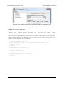
PuTTY is a free Windows terminal program that can send and receive bytes on a
serial port.
If you need to send and receive non-ASCII bytes, you can use the Pololu Serial Transmitter Utility for
Windows [http://www.pololu.com/docs/0J23].
Advanced users developing scripted applications
kermit [http://www.columbia.edu/kermit/] (Windows or Linux).
may
prefer
the
free
terminal
program
You can also write a computer program to use the serial port. The freely available Microsoft .NET framework for
Windows contains a SerialPort class that makes it easy to read and write bytes from a serial port. Here is some
example C# .NET code that uses the USB Communication Port:
// Choose the port name and baud rate.
//
Port Name must be determined from the Device Manager.
//
Baud rate is irrelevant for the USB Communication Port.
System.IO.Ports.SerialPort port = new System.IO.Ports.SerialPort("COM4", 115200);
// Connect to the port.
port.Open();
// Set the DTR line to 1.
port.DtrEnable = true;
// Transmit two bytes to the AVR: 0x61, 0x62
port.Write(new byte[]{0x61, 0x62}, 0, 2);
// Wait for a byte to be received on the RX line.
int response = port.ReadByte();
// Show the user what byte was received.
MessageBox.Show("Received byte: " + response);
// Set the DTR line to 0.
port.DtrEnable = false;
8. Using the USB Communication Port
Page 32 of 41
Pololu Orangutan SVP User's Guide
© 2001–2010 Pololu Corporation
// Disconnect from the port so that other programs can use it.
port.Close();
Communication on the AVR side
Writing programs for the USB Communications port on the AVR side is supported by two different sections of
the Pololu AVR C/C++ Library.
The SVP-specific functions section of the library provides the rts_enabled() and dtr_enabled() functions which
return the states of those control lines. Complete documentation of the SVP-specific functions can be found
in Section 13 of the Pololu AVR Library Command Reference [http://www.pololu.com/docs/0J18]. A high level
overview can be found in Section 6.j of the Pololu AVR C/C++ Library User’s Guide [http://www.pololu.com/docs/
0J20].
The Serial Port Communication section of the library provides many functions for serial communication,
all of which will work for the USB Communications port. Complete documentation of serial communication
functions can be found in Section 10 of the Pololu AVR Library Command Reference [http://www.pololu.com/docs/
0J18]. A high level overview can be found in Section 6.h of the Pololu AVR C/C++ Library User’s
Guide [http://www.pololu.com/docs/0J20].
8. Using the USB Communication Port
Page 33 of 41
Pololu Orangutan SVP User's Guide
© 2001–2010 Pololu Corporation
9. Using the TTL Serial Port
The Orangutan SVP’s USB Connection provides a serial port called the Pololu Orangutan SVP TTL Serial
Port which allows two-way communication between a personal computer and TTL-level serial devices at baud
rates between 300 bps and 115200 bps. This serial port can be used for communication between a computer and
an external serial device besides the AVR. It can also be used to debug the serial communication between the
AVR and an external serial device. If you want to communicate directly between the AVR and a computer, we
recommend using the USB Communications Port (see Section 8).
The bytes sent from the computer on this serial port will be transmitted on the TX line. Bytes received on the
D/RX line will be sent back to the computer. The bytes are sent and received eight bits at a time, non-inverted,
with no parity and one stop bit (8N1).
To use the TTL Serial Port, you must first determine what port name the operating system has assigned it.
To determine the port name in Microsoft Windows, open the Device Manager, expand the “Ports (COM & LPT)”
list, and look for the Pololu Orangutan SVP TTL Serial Port entry. The port name will be at the end of this line
in parentheses (e.g. “COM4”). In Windows, a given device will always be associated with the same port unless
you manually change its port assignment in the Device Manager (see Section 5.a).
Windows Vista device manager showing the Pololu Orangutan SVP.
To determine the port name in Linux, type ls /dev/ttyACM*. The port name will be one of the devices listed
there. If there are only three ports, then the TTL Serial Port will be /dev/ttyACM2 (the programmer will be /dev/
ttyACM0 and the USB communications port will be /dev/ttyACM1). If you see more than three ports, then you
should look at the output from dmesg when you plug in the Orangutan SVP to see which three ports are created;
the third port is the TTL Serial Port. In Linux, the port name depends on how many other devices are using the
USB CDC ACM driver to create virtual serial ports at the time the Orangutan SVP is plugged in.
After determining the port name, you can use any serial port software to communicate on that port.
There are many free terminal programs available, including PuTTY [http://www.chiark.greenend.org.uk/~sgtatham/
putty/] (Windows or Linux), Tera Term [http://hp.vector.co.jp/authors/VA002416/teraterm.html] (Windows), and Br@y
Terminal [http://sites.google.com/site/terminalbpp/] (Windows). To use any of these terminal programs, you must
specify the port name determined above, and the baud rate.
9. Using the TTL Serial Port
Page 34 of 41
Pololu Orangutan SVP User's Guide
© 2001–2010 Pololu Corporation
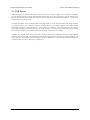
PuTTY is a free Windows terminal program that can send and receive bytes on a
serial port.
If you need to send and receive non-ASCII bytes, you can use the Pololu Serial Transmitter Utility for
Windows [http://www.pololu.com/docs/0J23].
Advanced users developing scripted applications
kermit [http://www.columbia.edu/kermit/] (Windows or Linux).
may
prefer
the
free
terminal
program
You can also write a computer program to use the serial port. The freely available Microsoft .NET framework for
Windows contains a SerialPort class that makes it easy to read and write bytes from a serial port. Here is some
example C# .NET code that uses the TTL Serial Port:
// Choose the port name and baud rate.
//
Port name must be determined from the Device Manager.
System.IO.Ports.SerialPort port = new System.IO.Ports.SerialPort("COM4", 115200);
// Connect to the port.
port.Open();
// Transmit two bytes: 0x61, 0x62
port.Write(new byte[]{0x61, 0x62}, 0, 2);
// Wait for a byte to be received on the RX line.
int response = port.ReadByte();
// Show the user what byte was received.
MessageBox.Show("Received byte: " + response);
// Disconnect from the port so that other programs can use it.
port.Close();
9. Using the TTL Serial Port
Page 35 of 41
Pololu Orangutan SVP User's Guide
© 2001–2010 Pololu Corporation
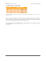
10. Motor Driver Truth Table
Input
Orangutan SVP output
PD7, PD6 PC7, PC6 M1A, M2A M1B, M2B motor effect LED on
H
H
L
H
“forward”*
green
H
L
H
L
“reverse”*
red
L
H or L
L
L
brake low
none
* Note that the concept of “forward” is arbitrary as simply flipping the motor leads results in rotation in the
opposite direction.
Motor 1 is controlled by pins PD7 (i.e. OC2A) and PC7. Motor 2 is controlled by pins PD6 (i.e. OC2B) and PC6.
Pins PD6 and PD7 are connected to the AVR’s eight-bit hardware PWM outputs, which allows you to achieve
variable motor speeds through hardware timers rather than software. This frees the CPU to perform other tasks
while motor speed is automatically maintained by the AVR timer hardware.
You
can
control
the
Orangutan
SVP’s
motors
using
the
functions
in
the
OrangutanMotors [http://www.pololu.com/docs/0J18/7] section of the Pololu AVR C/C++ Library, or you can write
your own code.
10. Motor Driver Truth Table
Page 36 of 41
Pololu Orangutan SVP User's Guide
© 2001–2010 Pololu Corporation
11. USB Power
When connected to a computer, the USB connection provides a 5 V power supply. If an external power supply is
present, the unit will run off of the external supply and not draw any power from USB. If only the USB power is
present, then by default the auxiliary processor will be powered from USB, but the AVR and the VCC power pins
on the board will not be powered.
An option is available for powering the entire board from USB. To power the board from USB, install a jumper
to connect VUSB to VCC. When the board is powered this way, the voltage regulator will conduct current
backwards, resulting in a VBAT around 4.6 – 5.0 V and a VCC around 4.3 – 4.6 V. In some cases, VCC will be
low enough to trigger brown-out detection on the AVR. Therefore, if you are having trouble powering your AVR
from USB, try changing your brown-out detection fuses to be tolerant of lower voltages.
Using the VCC-VUSB jumper can also cause other problems because the Orangutan is not being USB-compliant
whenever it draws more than 100 mA from the USB. If the Orangutan draws too much power from USB, the host
may respond by disconnecting the power supply to that port. Therefore, if you are having trouble powering your
AVR from USB, you may be drawing too much power.
11. USB Power
Page 37 of 41
Pololu Orangutan SVP User's Guide
© 2001–2010 Pololu Corporation
12. Upgrading Firmware
The firmware (program) that runs on the Orangutan SVP’s auxiliary processor can be upgraded with bug fixes or
new features.
Version 1.01 of the firmware fixes some bugs with the quadrature encoder support on the auxiliary
processor. If you use the auxiliary processor to read quadrature encoder outputs, we recommend
that you upgrade to this version so that these bugs will not cause you any problems. If you do not
use the auxiliary processor to read quadrature encoder outputs, then you do not need to upgrade.
Firmware Release Notes
Firmware version 1.00 is the original firmware for the SVP’s auxiliary processor, released in November 2009.
Firmware version 1.01 was released on January 15th, 2010. This version contains bug fixes related to the
quadrature encoder support that would occasionally trigger an encoder error and cause two encoder counts to be
lost.
Determining your firmware version in Windows
To determine the firmware version of the auxiliary processor using a Windows computer:
1. Connect the Orangutan SVP to your computer via USB.
2. Open up the Device Manager.
3. Double click on the “Pololu Orangutan SVP Programmer” entry in the “Ports (COM & LPT)” list.
4. In the Details tab, select the “Hardware Ids” property in the dropdown box.
5. The first value displayed should be something like USB\VID_1FFB&PID_0087&REV_0101&MI_00. The
number after the REV_ is your revision code. You can determine your firmware version by inserting a decimal
point after the second character of your revision code. If the revision code is “0100” then you have firmware
version 1.00. If the revision code is “0101” then you have firmware version 1.01.
Determining your firmware version in Linux
To determine the firmware version of the auxiliary processor using a Linux computer:
1. Connect the Orangutan SVP to your computer via USB.
2. Run the following command: lsusb -v
that has your firmware version number on it.
-d 1ffb:0087 | grep bcdDevice.
This should output a line
Upgrading firmware
To upgrade the auxiliary processor’s firmware, follow these steps:
1. Download the latest version of the firmware here:
◦ Firmware version 1.01 for the Orangutan SVP [http://www.pololu.com/file/download/
org06a_v1.01.pgm?file_id=0J317] (27k pgm) — released January 15th, 2009.
2. Connect the Orangutan SVP to your computer via USB.
3. Turn off the power to the Orangutan SVP’s AVR. The blue power LED should be off. You will have to
remove the VCC-VUSB jumper if it is present.
12. Upgrading Firmware
Page 38 of 41
Pololu Orangutan SVP User's Guide
© 2001–2010 Pololu Corporation
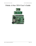
4. The bootloader line is shown in the picture below. Short this line to ground by connecting one end of
a wire to ground and touching the other end to the hole, being extremely careful not to touch any of the
neighboring parts. Ground is available in many places on the SVP; check the Orangutan SVP Reference
Diagram [http://www.pololu.com/file/download/orangutan_svp_reference_diagram.pdf?file_id=0J244] (82k pdf) if you
are not sure where to find ground. You may have to remove the Orangutan SVP’s LCD to access the
bootloader line.
The Orangutan SVP’s bootloader line.
5. The Orangutan SVP will now disconnect itself from your computer and reappear as a new device called
“Pololu org06a Bootloader”.
◦ Windows 7, Vista and Linux: The driver for the bootloader will automatically be installed.
◦ Windows XP: When the “Found New Hardware Wizard” is displayed, follow steps 6–8 in Section
5.a to get the driver working.
6. Once the bootloader’s drivers are properly installed, the green USB LED should be blinking in a double
heart-beat pattern, and there should be an entry for the bootloader in the “Ports (COM & LPT)” list of your
computer’s Device Manager in Windows.
7. Use a terminal program (such as Br@y Terminal [http://sites.google.com/site/terminalbpp/]) to connect to the
bootloader’s virtual serial port. In Windows, you can determine the port name of the bootloader (e.g. COM5)
by looking in the Device Manager. In Linux, you can determine the port name (e.g. /dev/ttyACM0) by
running dmesg. You can use any baud rate.
8. Type the following lower-case letters in to your terminal program to send them to the bootloader:
fwbootload. After each letter is sent, the bootloader should echo back the upper-case version of that letter.
After you have finished typing this sequence, you should see “FWBOOTLOAD” as the output from the
bootloader in your terminal program.
9. Now send lower-case “s”. The bootloader will spend a few seconds erasing the current firmware, and
then it will echo back an upper-case S. Do not disconnect the device from the computer after this point until
the upgrade is complete.
10. Now send the contents of the downloaded firmware upgrade file to the bootloader. The firmware
upgrade file is a plain-text (ASCII) file, so you can open it in a text editor (such as notepad), copy the whole
thing, and then paste it in to your terminal program. Alternatively, Br@y Terminal has a “Send File” button
you can use.
11. While the file is being sent, the bootloader will echo back period characters (“….”). This process will
take about 5 seconds. When the firmware upgrade is complete, the bootloader should echo back a pipe
character (“|”).
12. Upgrading Firmware
Page 39 of 41
Pololu Orangutan SVP User's Guide
© 2001–2010 Pololu Corporation
12. You can now unplug your SVP and plug it back in to the computer and use the new firmware.
If you run into problems during a firmware upgrade, please contact us [http://www.pololu.com/contact] for assistance.
12. Upgrading Firmware
Page 40 of 41
Pololu Orangutan SVP User's Guide
© 2001–2010 Pololu Corporation
13. Related Resources
The following list of resources might come in handy:
• WinAVR [http://winavr.sourceforge.net/]: free, open source C/C++ compiler for AVRs
• AVR Studio [http://www.atmel.com/avrstudio/]: free development IDE from Atmel that uses WinAVR as its
compiler
• ATmega324PA
documentation [http://www.atmel.com/dyn/products/product_card.asp?PN=ATmega324PA]:
ATmega324PA datasheet and additional documentation
• ATmega1284P
documentation [http://www.atmel.com/dyn/products/product_card.asp?PN=ATmega1284P]:
ATmega1284P datasheet and additional documentation
• Pololu AVR Library Command Reference [http://www.pololu.com/docs/0J18]: detailed information about
every function in the library.
• Pololu AVR Library User’s Guide [http://www.pololu.com/docs/0J20]: instructions on installing and using
the library, as well as sample programs.
• AVR Libc Home Page [http://www.nongnu.org/avr-libc/]
• Tutorial: AVR Programming on the Mac [http://bot-thoughts.blogspot.com/2008/02/avr-programming-onmac.html]
Please see the resources tab of your Orangutan’s product page for even more resources, including sample AVR
Studio projects.
Finally, we would like to hear your comments and questions over at the Orangutan Group [http://forum.pololu.com/
viewforum.php?f=10] on the Pololu Robotics Forum [http://forum.pololu.com/]!
13. Related Resources
Page 41 of 41