1
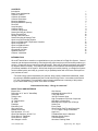
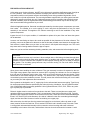
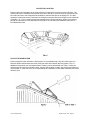
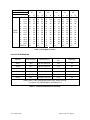
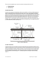
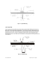
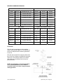
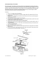
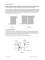
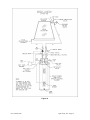
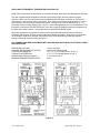
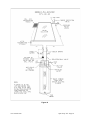
INSTALLATION
OPERATION
MAINTENANCE
MANUAL
OPEN LOOP/
OPEN LOOP PV
Alternate Energy Technologies, LLC.
PO Box 61326
Jacksonville, Florida 32236
904-781-8305
CONTENTS
Introduction
Basic Tools and Materials
Collector Location
Collector Orientation
Collector Dimensions
Mounting Hardware
Mounting Hardware Spacing
Pitch Pan
Array Mounting
Collector Piping
Collector Piping Detail
Sensor Mounting at Collector
Piping Through Roof
Storage Tank Placement
Sensor Mounting at Storage Tank
Open Loop Fluid Handling System
Open Loop Differential Temperature Controller
Open Loop Start-Up
Open Loop Maintenance
Open Loop PV System
Operational Checklist
Systems Parts List
Collector Yard Mount
1
1
2
2
3
4
7
7
8
9
9
10
10
10
11
11
12
13
13
14
15
16
16
INTRODUCTION
We at AET would like to extend our congratulations on your purchase of an Eagle Sun System. Years of
research and development backed by critical engineering have brought you the finest solar products you
can buy. Please take time to read this booklet thoroughly. Each step is outlined completely and clarified
by diagrams where necessary. All questions which arise from this material should be answered before
you attempt installation of the system. With a little thought and careful planning, your Eagle Sun System
can be installed quickly and easily by yourself or by a qualified plumber with a minimum of disruption to
your business or home.
“The solar energy system described by this manual, when properly installed and maintained, meets
the minimum standards established by the Florida Solar Energy Center, in accordance with Section
377.705, Florida Status. This certification does not imply endorsement or warranty of this product
by the Florida Solar Energy Center or the State of Florida.“
“Conservation for today… Energy for tomorrow.”
BASIC TOOLS AND MATERIALS
Electric Drill
Drill Index (w/ ½” and ¾” Wood Bits)
Hack Saw
Tubing Cutter
Tin Snips
16’ Tape Measure
24” Level
Flashlight
Extension Cord
Slip Joint Pliers
Needle Nose Pliers
Pipe Wretches, 10” & 14”
Open End Wrenches, 9/16 & 7/16
Screw Driver 6” Flat Blade
Screw Driver 6” Philips
Wire Stripper or Knife
www.aetsolar.com
Wire Cutters
Adjustable Wrenches 8”& 10
Torch and Striker
100 PSI Pressure Gage
High Temperature Pipe Joint Compound
Wire Nuts or Connectors
Miscellaneous Copper Pipe & Fittings
Solder Flux
Emory Paper
Silicon Caulk, Roof Tar and Putty Knife
½” I.D. Copper Tubing & Installation
Angle Iron
Threaded Rod, Nuts, & Washers
Stainless Screw Clamps
Thermal Adhesive
Aluminum Flashing Sheet
Open Loop / PV - Page 2
PRE-INSTALLATION CHECKLIST
Unlike other types of solar collectors, the AET solar collectors do not add a significant amount of weight to
the roof. However, if the collectors are placed at a steeper pitch than the roof itself, the additional
exposed flat surfaces could present extreme wind loading forces during sustained high winds. Check
local codes for roof load requirements. The mounting hardware supplied with your solar system has been
designed for specific wind loads, but only if adequate support structure is present with sufficiently strong
structural members (such as engineered trusses). Most building permit offices may be able to help you
with recommended roofing practices for your area.
Obtain all applicable permits. Structural members penetrated by the solar system components must meet
local codes. The installer is to run the piping in such a way that the performance of any fire rated
assembly is not reduced. This applies to the collector mounting as well as the installation of any other
system components.
Inspect the roof. If it is in poor condition, it is advisable to replace all or part of the roof where the system
will be attached.
Locate a roof area facing as close to due south as possible for the placement of the solar collectors. The
plumbing runs must be planned in advance so that the shortest possible route between the storage tank
and collector is made. Make sure you have no low points in the sloped horizontal pipe runs. This could
trap water and in freezing weather cause the pipe to rupture.
Make sure you have all the necessary plumbing materials, tools, and accessories before beginning work.
CAUTION!
Solar collectors become very hot when in direct sunlight with no fluid being circulated through them.
Extreme caution should be taken when standing near, or handling solar collectors in this state. Where
possible, cover the collectors with a tarpaulin or other opaque covering until you are ready to energize
the system. The circulating pump becomes very hot when running. Do not touch before allowing
sufficient time to cool down.
Wear gloves when handling the solar collectors! They get extremely hot when left exposed to the sun.
The bright orange plastic caps should be removed prior to placing the collectors on the roof otherwise
they may get so hot that they melt in place. Also, never try to lift the collectors by the pipe nipples. These
bend when hot and would damage the collector. You should have a tarp handy to keep the collectors
covered during the entire installation process. This will prevent the collectors becoming too hot to handle
as you make your final adjustments and connections.
Direct systems are designed to use ½” copper pipe for the collector/tank interconnect piping. Type M may
be used except where otherwise specified by the Authority Having Jurisdiction. Use only lead-free solder.
Use of 50/50 lead solder is expressly prohibited. Use of galvanized steel, CPVC, PVC, PEX or any other
type of plastic pipe is prohibited.
Dielectric nipples must be used on all connections to the tank. These are used wherever copper and
galvanized lines are connected together. This is a requirement of the Uniform Plumbing Code. Typically,
galvanized pipe nipples are used for all connections into the tank, which has ferrous female standard pipe
thread, 3/4" nominal (3/4" inside diameter). One side of a dielectric union fits a standard galvanized pipe
nipple, and the other side is brass or bronze for soldering to a copper pipe.
With solar tanks, the cold input from the pressurized supply line to the house (either city water or well
water) must be fed into the tank inlet. This is marked "Cold Inlet" and is located on top of the tank. There
is a long plastic tube attached internally to this connection so that incoming cold water is directed
immediately to the bottom of the tank, and therefore does not mix and cool down the hot water. A cold-
www.aetsolar.com
Open Loop / PV - Page 3
water shutoff valve must be installed above this connection so that water flow may be completely stopped
in the event of a leak, repair, or maintenance.
The hot water output to the house from the tank should be connected to the port labeled "Hot Outlet" on
the top of the tank. Again, a dielectric union must be used where a connection is made between
galvanized and copper pipes. A mixing valve must be installed at this point to limit the temperature of
water delivered to the home.
All hot water lines should be insulated with at least 1/2" thick heat resistant rubber tubing insulation such
as Armstrong Armaflex.
In most instances, the solar collectors can be attached to the roof using the standard mounting hardware
provided with the solar system. Certain types of roofing will require special attention for proper mounting.
For example, a clay tile or cement tile roof. Complete roofing attachment methods of solar collectors for
these various types of roofs are beyond the scope of this manual. The manual will describe and illustrate
some of these approved mounting techniques. A competent contractor should be used to ensure that all
roof penetrations and attachment points are not a source of rainwater leakage later on. Standard
plumbing roof jacks or solar industry copper flashings may be used for plumbing penetrations in most
cases.
The collectors should be canted slightly toward the inlet side to ensure they drain completely when
maintenance is required on the system.
CAUTION!
Photovoltaic modules produce electricity even in minimal sunlight. Keep the PV module covered
during the installation process and when performing system maintenance. The PV system toggle
switch should be in the off position until you are ready to energize the system.
Electrical connections should only be made after the plumbing system is fully installed and ready to be
charged. Insure that the controller or the PV system toggle switch is in the “OFF” position until you are
ready to energize the pump. Remember to remove all collector/module coverings prior to energizing the
system.
NOTE: All collectors are to be mounted vertically, sloped in order to be completely void of fluid when
drained, and oriented in such manner as described below under COLLECTOR LOCATION.
www.aetsolar.com
Open Loop / PV - Page 4
COLLECTOR LOCATION
Proper location and orientation of the solar collectors is important for maximum system efficiency. The
collectors should be unshaded for the middle six hours of the day in each month of the year and should
be located as close to the storage tank as possible to minimize heat loss in the piping runs. The best
orientation is achieved when the collectors are facing due south and tilted at an angle from the horizontal
of latitude + 10°. Figure 1 below shows many alternatives for collector mounting. When roof mounting,
placing the collectors as close as possible to the peak of the roof will make installation easier due to
increased attic access
COLLECTOR ORIENTATION
Proper tilt angle for solar collectors is latitude plus 10° (see latitude map). This favors the winter sun
because ambient temperatures are lower during the winter and collector efficiency suffers. This 10°
additional tilt equalizes year round performance. Spacing can be determined from Table 1. When the
collectors are mounted one behind the other, they are spaced apart so that in the morning and afternoon
on December 21, when the sun is at its lowest altitude, the collectors will not shade each other and cause
efficiency loss.
www.aetsolar.com
Open Loop / PV - Page 5
LATITUDE
COLLECTOR TILT
ROOF
PITCH
FLAT
5°
1/12
9°
2/12
14° 3/12
18° 4/12
23° 5/12
27° 6/12
30° 7/12
34° 8/12
37° 9/12
40° 10/12
43° 11/12
45° 12/12
VERTICAL
25° N
35°
A
B
29
96
25
83
22
74
17
66
14
61
10
58
7
58
4
58
0
58
-2
58
-4
58
-7
58
-8
58
-44
30° N
40°
A
B
33 113
29
93
26
82
22
72
18
66
14
60
11
58
8
58
5
58
3
58
0
58
-3
58
-4
58
-41
35° N
45°
A
B
37 145
33 113
30
77
26
82
22
74
18
66
15
61
13
58
9
58
7
58
4
58
-2
58
0
58
-37
40° N
50°
A
B
41 145
37 132
34 110
30
92
26
81
22
72
19
66
17
58
13
58
11
58
8
58
6
58
4
58
-33
45° N
55°
A
B
44 145
41 133
38 115
34
95
30
85
26
74
23
68
21
58
17
58
15
58
13
58
10
58
8
58
-29
50° N
60°
A
B
48 145
44 141
41 118
38
98
34
87
30
77
27
70
25
58
22
58
19
58
17
58
14
58
13
58
-25
Table 1. All Lengths in inches
COLLECTOR DIMENSIONS
Collector
Gross Area (ft²)
Dimensions (in)
Transparent Area
(ft²)
Weight (lb)
AE-21
20.8
35-3/16 x 85-3/16
19.2
74
AE-24
23.7
35-3/16 x 97-3/16
21.9
84
AE-26
25.3
47-3/16 x 77-3/16
23.6
90
AE-28
27.9
47-3/16 x 85-3/16
26.1
99
AE-32
31.8
47-3/16 x 97-3/16
29.9
113
AE-40
39.7
47-3/16 x 121-3/16
37.4
153
Tested: SRCC, FSEC, Metropolitan Dade County, Miami Test Lab,
TUV (DIN 4757), RAPPERSWILL, ONORM M7714
Table 2. Collector Dimensions for AE series
www.aetsolar.com
Open Loop / PV - Page 6
MOUNTING HARDWARE
Provided in the Eagle Sun package is specially designed mounting hardware to speed collector
installation. This hardware consists of ten LOCK-TIGHT hinge sets, four roof brackets, two rear struts,
and bolts (Figures 3, 4, and 5).
a) After locating the mounting points from Table 1, the mounting bracket holes should be drilled.
b) A heavy coating of sealant should be applied to the bottom of the flashing plate, which should fit
flat against the roof. It is necessary for the plate to slide under the above shingles to insure proper
drainage of water.
c) The bottom of the roof bracket and the area around the threaded rod should also be thoroughly
coated with tar sealant. When the bracket is set in place, alignment with the collector hinges is
necessary before final tightening of the nuts. This should be completed before the sealant has
time to set.
d) The threaded rod is fastened through a 2’ x 6” wood or 2” x 2” x ¼” steel angle bracket under the
roof as shown.
e) The rear struts should be cut and drilled to conform to Table 1. All bolts should be tightened
securely. A stainless steel washer should be placed where the threaded rod passes through the
aluminum bracket.
It is very important that the penetrations through the roof be well sealed. It should be carefully checked
that all bolts are coated with tar and that no leaks are possible.
www.aetsolar.com
Open Loop / PV - Page 7
There are three acceptable ways to secure the collector mounting brackets to the roof.
1. Spanner Mounting
2. Lag Bolt Mounting
3. J-Bolt Mounting
SPANNER MOUNTING
In spanner mounting after the brackets are positions on the chalk line, a 3/8” hole is drilled between the
rafters. An aluminum flashing is positioned over the hole where the top of the flashing is extended up
under the shingle above the 3/8” hole and extends down over it. Caulk is applied between the flashing
and the roof. The bracket is then positioned over the 3/8” hole using sealant between the bracket and the
flashing. A piece of 3/8” all-thread is then inserted through the hole. A washer and nut secures the allthread to the bracket (be sure the seal underneath the washer and on top of the nut). The all-thread rod
should extend about 4” below the roof rafters. Drill a 3/8” hole in a 2 x 4 and insert the all-thread rod
through it. The 2 x 4 should span 2 rafters. With a washer and double bolt secure the all-thread to the 2 x
4. Tighten down until the bracket is tightly secured to the roof. Be careful not to over-tighten and bell out
the roof underneath the bracket. (See Figure 6)
Figure 6. Spanner Mounting
LAG BOLT MOUNTING
In lag bolt mounting you must locate the center of the rafters along the top and bottom chalk lines. One
method is to have one man on the roof and another in the attic. Using a hammer the man on the roof can
tap the roof and determine where it is denser sounding. The roof man can drill a pilot hole while the attic
man helps with distance corrections. Then the attic man can call of the distance to the next rafter while
the roof man drills corresponding pilot holes. Flashing the brackets is done as previously described.
Secure the brackets to the roof using a ¼” x 3” stainless lag screw, a flat washer, and a lock washer
(Figure 7).
www.aetsolar.com
Open Loop / PV - Page 8
Figure 7. Lag Bolt Mounting
J-BOLT MOUNTING
J-bolt mounting is done very similar to lag screw mounting except instead of drilling into the center of a
rafter, a hole must be drilled directly beside a rafter. The size of the hole must be slightly larger than the
bolt diameter. This is more easily accomplished if the attic man would drill a pilot hole through the roof
along side the chosen rafter. Fit the bolt through the mounting brackets and insert the bolt (J side first)
through the hole in the roof. Work the J underneath the rafter. Pull the J-bolt snug against the rafter
before tightening the nut. Use double nuts or lock-washers to securely fasten the mounting bracket to the
J-bolt (Figure 8).
Figure 8. J-Bolt Mounting
www.aetsolar.com
Open Loop / PV - Page 9
MOUNTING HARDWARE SPACING
AE-Series
Center Line to Center Line (in.)
Model
Size (ft)
Outside Box Dim. (in.)
AE-MH
AE-FM
AE-RM
AE-21
3x7
35.1875 x 85.1875
88.4375
88.9375
86.9375
AE-24
3x8
35.1875 x 97.1875
100.4375
100.9375
98.9375
AE-26
4 x 6.5
47.1875 x 77.1875
80.4375
80.9375
78.9375
AE-28
4x7
47.1875 x 85.1875
88.4375
88.9375
86.9375
AE-32
4x8
47.1875 x 97.1875
100.4375
100.9375
98.9375
AE-40
4 x 10
47.1875 x 121.1875
124.4375
124.9375
122.9375
MSC-Series
Center Line to Center Line (in.)
Model
Size (ft)
Outside Box Dim. (in.)
MSC-MH
MSC-FRM
MSC-FM
MSC-21
3x7
35.8750 x 86.1250
90.5
87.375
37.125
MSC-24
3x8
35.8750 x 98.1250
102.5
99.375
37.125
MSC-26
4 x 6.5
47.8750 x 78.1250
82.5
79.375
49.125
MSC-28
4x7
47.8750 x 86.1250
90.5
87.375
49.125
MSC-32
4x8
47.8750 x 98.1250
102.5
99.375
49.125
MSC-40
4 x 10
47.8750 x 122.1250
126.5
123.375
49.125
Table 3. Distance between centerlines of top and bottom mounts for all AE and MSC series
PITCH PAN
The pitch pan is necessary any time standing
water is encountered (Figure 9). The purpose is to
provide an adequate seal around any penetration
in the roof.
The pitch pan is placed in the proper position and
flat on the roof. Its flange is sealed with roofing felt
and hot tar. The holes are sealed on the inside
with roofing tar to a sufficient level to insure a
permanent seal.
NOTE: All penetrations in structural members
or fire rated assemblies are to be made in
accordance with local codes using acceptable
roofing practices.
www.aetsolar.com
Open Loop / PV - Page 10
ARRAY MOUNTING ON TILE ROOFS
Tile roofs are a little more difficult to mount solar collectors on but following this procedure will render a
leak free installation. The solar panels are mounted on two rails located at the top and bottom of the solar
collectors. The collectors are secured to the rails using the AE rack mount hardware (AE-RM). The 1-5/8”
Aluminum unistrut rails are anchored to the roof by using six or ten inch stainless steel 3/8” hanger bolts.
These bolts are lag screw on the bottom and 3/8 NPT thread on the top. A ten foot length of unistrut
should be anchored at three points, the middle and both ends.
Procedure:
1. Cut 12” x 12” square pieces of lead flashing.
2. Locate the roof rafters beneath the tile where the hanger bolts will be attached. Drill a 3/8” hole
through the tile.
3. Slide the 12” x 12” lead flashing under the tile located above the 3/8” hole, then drill through the
lead flashing into the hole.
4. Screw lag portion of the 3/8” hanger bolt into the rafter.
5. Cut strips of the lead flashing about 1-1/2” long and wide enough that when you fold it into a tube
is slightly larger in diameter as the hanger bolt.
6. Using an acid core solder, weld the seam of the tube together.
7. Slip this tube over the top of the hanger bolt protruding from the roof, and then solder it to the 12”
x 12” lead flashing.
8. Thread down a stainless 3/8” nut to the bottom of the thread and seal the top of lead tube to the
nut with a polybutylene caulk.
9. Slip a 3/8” stainless washer on top o the nut.
10. Place the 1-5/8” aluminum unistrut rail on the hanger bolt and secure with another 3/8” stainless
washer and net.
11. The rail is now secured, weather tight to the tile roof. Next, mount the AET solar collector to the
rail using the AE rack mounts (AE-RM). See Figure 10.
Figure 10
www.aetsolar.com
Open Loop / PV - Page 11
COLLECTOR PIPING
The piping of the system should be considered before a final decision is made on how the collectors are
mounted. Piping should be made of copper tube of the type meeting local codes, insulated with Armaflex
or similar, and painted or wrapped with aluminum tape where exposed to ultraviolet radiation.
Care should be taken in the spacing of collectors as attachment of piping is easiest with properly aligned
collectors. The collectors and piping to the storage tank should be slightly sloped downward (3” in 8 feet)
to allow draining in case of freezing conditions. Piping should be adequately supported for correct pitch
and supports shall be designed to avoid compressing or damaging the insulation material. Soldered
connections should be made with 95/5 solder.
Figure 11
Figure 12
COLLECTOR PIPING DETAIL
The outlets of the collector are 1” copper pipe nipples (Figure 13). They should be piped as shown with
provisions for an automatic air vent. This will prevent air lock and subsequent loss of system efficiency.
The copper union makes attachment of piping to collector easy. Teflon tape or high temperature, high
quality pipe sealant should be used when making threaded connections.
The collector inlets should be piped similarly but without the automatic air vent.
Figure 13
www.aetsolar.com
Open Loop / PV - Page 12
SENSOR MOUNTING AT COLLECTOR
The controller heat sensor is mounted to the nipple outlet of the collector (Figures 14). A stainless steel
screw clamp should be used. The entire nipple should be wrapped thoroughly with insulating tape so that
the sensor is isolated from the outside air.
Figure 14
PIPING THROUGH THE ROOF
Piping through the roof should be weatherproofed as shown in Figure 15. One inch holes are drilled
through the roof on the same plane as the supply and return header nipples. Do not drill the hole above
the supply header of the collector. This will prevent the collector from draining. Placing the hole below the
supply header is acceptable, but it is more aesthetic if it is located on the same plane. A copper flashing
is placed around the hole with its base cemented to the roof and its upper edges slid under the adjoining
shingle. The copper tube supply and return line is then pushed up through the hole in the flashing. A
“coolie cap” is then slid over the copper tube till it meets the flashing. After piping to the collectors is
completed, the “coolie cap” is soldered to the copper tube. Polybutylene adhesive is then placed on the
top and bottom of the flashing, providing a weatherproof seal. The sensor wire should also be run through
the return flashing.
Figure 15
www.aetsolar.com
Open Loop / PV - Page 13
STORAGE TANK PLACEMENT
To minimize expense and heat loss, the tank should be placed near the collectors and central to points of
greatest water demand. It should be located in as warm a spot as possible. It should be located with
adequate ventilation, with a minimum of 6-8 inches of clearance and with ready access to controls and
serviceable parts.
Provision should be made to prevent water damage in case of leakage. A catch pan with a minimum of
3/4” drain line at least 2” in height may be installed and pitched for proper drainage where the tank is
installed in or above the living space. Electrical service of 240V should be available for the element and
110V for the pump and controller.
SENSOR MOUNTING AT STORAGE TANK
On the closed loop Rheem tanks the heat sensor mounting is located behind the round cover located at
the bottom front of the 80 gallon storage tank.
Procedure:
1. The round cover located on the bottom front of the tank should be removed and the fiber glass
insulation pushed aside so that the wall of the tank is accessible.
2. Remove the ½” brass plug from the tank.
3. After sealing the ½” lug sensor with teflon tape or pipe tape, screw it into the ½” threaded hole.
4. Attach 18/2 sensor wire to the wires of the sensor. It does not matter which sensor wire is
attached to the thermostat wire.
5. Run the thermostat wire up the tank to the controller and attach it to the terminals marked tank or
water.
6. Replace the insulation and cover.
OPEN LOOP FLUID HANDLING SYSTEM
An Eagle Sun open loop solar water heater operates by circulating water from the storage tank to the
solar collectors when the collectors are at a higher temperature than the tank. This function is controlled
by a differential temperature controller with heat sensors. When the collectors are warmer than the water
inside the tank, the controller switches on the pump. (Figure 16).
A recirculation feature of the controller provides freeze protection. When the sensor at the collector
indicates freezing temperatures, the pump is switched on and warm water is circulated through the
collectors until warmed. The pump is then automatically switched off. This cycle repeats periodically until
freezing conditions no longer exist. When a hard freeze is imminent or a power failure occurs, the system
should be drained by closing the two ball valves that isolate the collector loop and opening the two drain
valves that allow the collectors to drain.
The system also includes a freeze protection valve at the collector outlet pipe. This valve is designed to
open at a set temperature 35-45°F and allow fluid to pass across the collectors to prevent freezing of the
collector manifold. When operating properly the valve will drip water until a suitable temperature is
reached at the valve.
Automatic air vents in the top of the system prevent air locks. Care should be taken that no air can be
trapped in piping to and from the collectors. Water returns to the tank from the collectors via a drop tuber
that extends halfway down the interior of the tank. This allows the returning water to stratify properly.
A check valve in the return line from the collectors prevents thermosiphon losses during the night.
Temperature and pressure relief valves protect the system from damage.
A backup electric element is provided in the top of the tank to supply hot water during inclement weather.
Power required is 240 volts.
www.aetsolar.com
Open Loop / PV - Page 14
Figure 16
www.aetsolar.com
Open Loop / PV - Page 15
OPEN LOOP DIFFERENTIAL TEMPERATURE CONTROLLER
NOTE: When instructions are provided in the controller package, follow those and disregard the following.
The open loop differential temperature controller controls the pump to achieve maximum system
efficiency. When one of the two heat sensors provided with the unit raises nominally 10° F above the
other sensor, a power control relay is energized. Then, when the first sensor drops to within 5° F of the
second sensor, the control relay contacts are opened. As long as the “turn-on differential of 10° F is
exceeded, the control relay remains open. (The 5° F value is designated as the “turn-off differential.”) The
first sensor is called the COLLECTOR sensor, since when properly installed monitors the temperature of
the water in the solar collector. The second sensor is called the STORAGE sensor.
Mount the controller in any position or location that is convenient and sheltered from the elements.
Aesthetics and economy of running power leads should dictate the location, since there is no restriction
on the length of leads to the sensors. Connections to the circuit terminal strip inside the controller
enclosure should be made according to Figure 17.
ALL CONNECTIONS SHOULD BE MADE WITH ACCORDANCE WITH LOCAL ELECTRICAL CODES.
SPECIFICATIONS:
OPERATING VOLTAGE:
CONTROL RELAY CONTACT RATING:
TURN-ON DIFFERENTIAL:
TURN-OFF DIFFERENTIAL:
SENSOR MATCHING ACCURACY:
MAXIMUM SENSOR TEMPERATURE:
120 vac, 60 Hertz
One third HP inductive load
10° F (+1° F) for Storage Sensor at 135° F
4° F (+1° F) for Storage Sensor at 135° F
1° F or less at 135° F
300° F
Figure 17
www.aetsolar.com
Open Loop / PV - Page 16
OPEN LOOP START-UP
After visual inspection of the complete system, it is ready for filling and pressure testing. All drain valves
should be closed, all other valves opened. The air vent caps should be loosened two turns to allow air to
escape the system. The cold water inlet valve should then be opened slowly and system checked for
leaks as it fills. When the system is completely full, indicated by water escaping from the air vent when
the valve is depressed it should be pressure checked with normal pressure for 30 minutes.
Once the system has been pressure tested and repaired if required, the control system can be energized.
On an A/C controlled system, plug the controller into a 115/120 VAC outlet. Set the “ON DIF” dial to 10
and the “HI LIM” to 135. Move the “RELAY” (pump) override switch to the “AUT” (automatic) position. On
a PV controlled system, switch the toggle to the “ON” position. If the sun is shining and the storage tank is
cool, the pump should come on and water should flow through the collector. The first water through the
collectors will be very hot but should stabilize in about 15 minutes. The return lines from the collectors
should be hotter than the inlet lines and the collector glass should be slightly warmer than ambient
temperature.
If the differential temperature control offers a freeze protection mode, testing of the sensor can be made
at night when the pump is not normally working. A piece of ice set on the collector sensor should be
sufficient to turn the pump on. The pump should turn off as soon as the sensor has a few seconds to
warm back up when the ice is removed. Caution should be exercised when working on the roof at night.
OPEN LOOP MAINTENANCE
Maintenance of an open loop system is straightforward. The tank should be partially drained every 6
months to allow minerals to be removed preventing scale build up (this is recommended for all water
heaters). The wye strainer should be cleaned at least once a year or more often if harsh water conditions
exist. The power should be switched off, the piping drained, and the screen removed and cleaned.
The collector glass should be kept clean for best system performance. Rainwater will usually suffice but a
garden hose can be used during dry weather. The air vent caps should be loosened two turns for proper
operation and best system performance.
OPEN LOOP PV SYSTEM
The single photovoltaic module, attached to the top of the solar collector (Figure 18) operates a brushless
12 VAC or 24 VAC pump at a speed relative to the amount of available sun. When clouds pass over, the
pumping operation slows to allow the water to remain in the collector longer for continued heating. When
the sun goes down in the evening the pumping action will stop.
The solar system is installed as per the open loop installation manual. The photovoltaic module will
replace the differential control and sensors. Be sure to mount the panels on the same plane as the solar
collector. A toggle switch is to be installed, as per the “Direct PV System” diagram, to serve as a service
disconnect should the solar system require maintenance or for purposes otherwise directed in this
manual.
When wiring the photovoltaic module to the circulating pump use 16 gage stranded double exterior PVC
jacketed wire for lengths up to 85 feet for 10 and 25 watt modules. Use 14 gauge for over 85 feet for a
module over 1.4 amps. When wiring the module to the pump, remember that the black wire is always
ground and the red wire is the hot wire. Do not reverse the polarity.
www.aetsolar.com
Open Loop / PV - Page 17
Figure 18
www.aetsolar.com
Open Loop / PV - Page 18
OPERATIONAL CHECKLIST
Before the system is turned on, the piping and electrical systems should be evaluated to see if they match
the supplied drawings. If you are satisfied that the system is installed correctly, it should be filled and
powered according to the preceding instructions. When the system is in the operational mode, care
should be taken to check all piping for leaks and to make sure sufficient insulation has been used to
provide maximum system efficiency. All modes of operation should be checked by the installer to assure
proper functioning under all conditions.
Although operational checks may include physical contact (by touch) with the collector return pipe and the
pump housing (for heat and or vibration), the addition of thermometers in the feed and return pipes or a
flow meter in the feed line would provide a visual indication of operation. These items are not part of the
supplied system and would be available through your solar contractor/installer.
VACATION PROCEDURES
If no hot water is to be used for some time, the system should be de-energized and drained. Follow
instruction below; “Leaks in the solar loop” to shut the system down. To re-energize the system, refer to
the OPEN LOOP START-UP section of this manual.
TROUBLESHOOTING GUIDE
Problems with systems usually fall under two categories: system leaks or lack of sufficient solar heated
water.
LEAKS
If leaks exist, the system should be shut down for repairs.
Leaks at the tank:
1. Turn off the circuit breaker to the water storage tank and unplug the power to the controller (A/C
controlled) or switch the toggle switch to the off position (PV controlled).
2. Close the cold water shut-off valve and close the isolation ball valves to the collector(s).
3. Connect one end of a garden hose to the tank drain valve placing the opposite end of the hose at
a location suitable for draining.
4. Open the tank drain valve and the hot water valve of any fixture with the premises served by the
water heater.
5. Allow the tank to drain and make the necessary repair.
6. Recharge the system as described in the Open Loop Start-Up section of this manual.
Leaks in the solar loop:
1. Unplug the power to the controller (A/C controlled) or switch the toggle switch to the off position
(PV controlled).
2. Close the isolation ball valves to the collector(s).
3. Connect one end of a garden hose to the collector feed boiler drain valve and a washing machine
hose to the collector return boiler drain. Place the opposite end of the garden hose in a location
suitable for draining and the opposite end of the washing machine hose in a 5 gallon bucket.
4. Open the collector feed drain valve and then slowly open the collector return drain valve. The
majority of fluid in this part of the system should drain through the collector feed drain valve.
5. Allow the solar loop to drain and make the necessary repair.
6. Recharge the system as described in the Open Loop Start-Up section of this manual.
There is a possibility that what appears to be leaks may be condensation on the pipes. Also water
escaping for the T&P relief valve may be an indication of proper function as they are designed to vent off
excess temperature and pressure.
www.aetsolar.com
Open Loop / PV - Page 19
INSUFFICIENT HOT WATER
If insufficient hot water is available a system malfunction may not be indicated. A low amount of solar
radiation or heavy water demand can be the cause.
If no excessive demands are put on the system and ample solar radiation is available, the system should
operate properly. The pump should run each sunny day until a full supply of hot water is stored. If the
pump does not run, there is a problem on the electrical end of the system. Either the pump, controller, or
sensors are malfunctioning. The controller can be bypassed by running a power cable directly to the
pump and checking its function separate from the control system. Make sure that the problem is not a
blown fuse or a tripped breaker. If the pump runs normally when powered externally, the control circuit is
the problem area. Eagle Sun controllers use thermistor sensors to determine modes of operation. A
controller tester is available from AET for checking differential function. Check sensor wiring. If no faulty
wiring can be discovered, replace sensors.
If the pump is running all the time, even when the collectors are cool, then the storage sensor or collector
sensor may be open. It is also possible that the sensor wire itself is at fault. To check this, test the
continuity with an ohm meter. Be sure to disconnect the sensor when performing this test. Test the wire
with both ends open, then retest often twisting the 2 sensor wires together at one end. The system can
be set on a timer or switched on manually until the controller is properly functioning.
CONDENSATION ON COLLECTORS
If condensation occurs inside the collectors, ¼” vent holes should be drilled in the lower side of the
collector. Three holes should be drilled, one at each end of the bottom of the collector and one in the
center. These holes should be drilled 1” from the base of the collector
This should clear up any condensation within three days.
OTHER PROBLEMS
A noisy pump is an indication of worn bearings obstruction or loss of prime. As a rule of thumb about 8 to
12 degrees should be expected as a normal gain across a collector in bright sun at proper flow rate.
SYSTEM PART NUMBERS
This manual covers the installation of the following FSEC approved system model numbers:
D-80-40, D-120-64, DPV-80-40 and DPV-120-64
SYSTEM PARTS LISTING (A/C Controlled)
COMPONENT
Solar Collector(s)
Water Storage Tank
Circulation Pump
Differential Control
www.aetsolar.com
MANUFACTURER
Alternate Energy Technologies, LLC
Alternate Energy Technologies, LLC
American Water Heater
Richmond (Rheem) Water Heaters
TACO, Inc.
Grundfos Pump
Goldline Controls
IMC Instruments
MODEL
AE-32 (-64 systems) or
AE-40 (-40 systems)
SE62-80H-045S or
81VR80-TC-1
003-BC4 or
UP15-10B5
GL-30 (LCO) or
Eagle 1 or Eagle 2
Open Loop / PV - Page 20
SYSTEM PARTS LISTING (PV Controlled)
COMPONENT
Solar Collector(s)
Water Storage Tank
Circulation Pump
Differential Control (PV)
MANUFACTURER
Alternate Energy Technologies, LLC
Alternate Energy Technologies, LLC
American Water Heater
Richmond (Rheem) Water Heaters
Laing Thermotech
SunWise Technologies
Yingli Solar
MODEL
AE-32 (-64 systems) or
AE-40 (-40 systems)
SE62-80H-045S or
81VR80-TC-1
D5Solar/090B
OEM-10 or
PV-10
COLLECTOR YARD MOUNT
When no sunny roof area is available or for “show” systems, the collectors can be mounted on the ground
as shown in Figure 19. The piping and control wiring to the tank should be insulated and buried. It is
important that the length of these piping runs be minimized.
Notes:
• Front edge of collector should be 18” above ground
• Use washers on all bolted wood connections
• All pieces must be measured and cut to orient collector at latitude + 10° – consult trigonometric
reference.
• Piping to collector may be buried.
Figure 19
NOTE: All collectors are to be mounted vertically, sloped in order to be completely void of fluid when
drained, and oriented in such manner as described under COLLECTOR LOCATION.
www.aetsolar.com
Open Loop / PV - Page 21