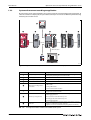
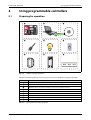
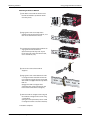
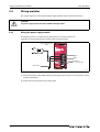
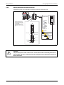
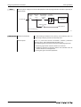
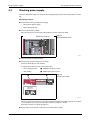
1
MITSUBISHI ELECTRIC
MELSEC-L Series
Programmable Controllers
Quick Start Guide
15032011
Version A
MITSUBISHI ELECTRIC
INDUSTRIAL AUTOMATION
About this manual
The texts, illustrations, diagrams and examples in this manual are provided for
information purposes only. They are intended as aids to help explain the
installation, operation, programming and use of the programmable controller of
MELSEC L series.
If you have any questions about the installation and operation of any of the
products described in this manual please contact your local sales office or
distributor (see back cover).
You can find the latest information and answers to frequently asked questions
on our website at www.mitsubishi-automation.com.
MITSUBISHI ELECTRIC EUROPE B.V. reserves the right to make changes to this
manual or the technical specifications of its products at any time without notice.
© 2005
Quick Start Guide
MELSEC-L Series Programmable Controllers
Version
A
03/2011
Revisions / Additions / Corrections
akl —
Safety guidelines
Safety guidelines
For use by qualified staff only
This manual is only intended for use by properly trained and qualified electrical technicians who are
fully acquainted with the relevant automation technology safety standards. All work with the hardware described, including system design, installation, configuration, maintenance, service and testing of the equipment, may only be performed by trained electrical technicians with approved qualifications who are fully acquainted with all the applicable automation technology safety standards
and regulations. Any operations or modifications to the hardware and/or software of our products
not specifically described in this manual may only be performed by authorised Mitsubishi Electric
staff.
Proper use of the products
The programmable controllers of the MELSEC L series are only intended for the specific applications
explicitly described in this manual. All parameters and settings specified in this manual must be observed. The products described have all been designed, manufactured, tested and documented in
strict compliance with the relevant safety standards. Unqualified modification of the hardware or
software or failure to observe the warnings on the products and in this manual may result in serious
personal injury and/or damage to property. Only peripherals and expansion equipment specifically
recommended and approved by MITSUBISHI ELECTRIC may be used with the programmable controllers of the MELSEC L series.
All and any other uses or application of the products shall be deemed to be improper.
Relevant safety regulations
All safety and accident prevention regulations relevant to your specific application must be observed
in the system design, installation, configuration, maintenance, servicing and testing of these products. The regulations listed below are particularly important in this regard. This list does not claim to
be complete; however, you are responsible for being familiar with and conforming to the regulations
applicable to you in your location.
● VDE Standards
– VDE 0100
Regulations for the erection of power installations with rated voltages below 1000 V
– VDE 0105
Operation of power installations
– VDE 0113
Electrical installations with electronic equipment
– VDE 0160
Electronic equipment for use in power installations
– VDE 0550/0551
Regulations for transformers
– VDE 0700
Safety of electrical appliances for household use and similar applications
– VDE 0860
Safety regulations for mains-powered electronic appliances and their accessories for household use and similar applications.
● Fire safety regulations
● Accident prevention regulation
– VBG No. 4
Electrical systems and equipment
MELSEC-L Series Quick start guide
I
Safety guidelines
Safety warnings in this manual
In this manual special warnings that are important for the proper and safe use of the products are
clearly identified as follows:
II
m
DANGER:
b
CAUTION:
Personnel health and injury warnings.
Failure to observe the safety warnings identified with this symbol can result in health and injury
hazards for the user.
Equipment and property damage warnings.
Failure to observe the safety warnings identified with this symbol can result in damage to the
equipment or other property.
Safety guidelines
General safety information and precautions
The following safety precautions are intended as a general guideline for using PLC systems together
with other equipment. These precautions must always be observed in the design, installation and operation of all control systems.
m
DANGER:
● Observe all safety and accident prevention regulations applicable to your specific application. Always disconnect all power supplies before performing installation and wiring work
or opening any of the assemblies, components and devices.
● Assemblies, components and devices must always be installed in a shockproof housing fitted
with a proper cover and fuses or circuit breakers.
● Devices with a permanent connection to the mains power supply must be integrated in the
building installations with an all-pole disconnection switch and a suitable fuse.
● Check power cables and lines connected to the equipment regularly for breaks and insulation
damage. If cable damage is found immediately disconnect the equipment and the cables
from the power supply and replace the defective cabling.
● Before using the equipment for the first time check that the power supply rating matches that
of the local mains power.
● Take appropriate steps to ensure that cable damage or core breaks in the signal lines cannot
cause undefined states in the equipment.
● You are responsible for taking the necessary precautions to ensure that programs interrupted by brownouts and power failures can be restarted properly and safely. In particular, you
must ensure that dangerous conditions cannot occur under any circumstances, even for brief
periods. EMERGENCY OFF must be switched forcibly, if necessary.
● Residual current protective devices pursuant to DIN VDE Standard 0641 Parts 1-3 are not
adequate on their own as protection against indirect contact for installations with PLC
systems. Additional and/or other protection facilities are essential for such installations.
● EMERGENCY OFF facilities conforming to EN 60204/IEC 204 and VDE 0113 must remain fully
operative at all times and in all control system operating modes.The EMERGENCY OFF facility
reset function must be designed so that it cannot ever cause an uncontrolled or undefined
restart.
● You must implement both hardware and software safety precautions to prevent the possibility of undefined control system states caused by signal line cable or core breaks.
● When using modules always ensure that all electrical and mechanical specifications and
requirements are observed exactly.
MELSEC-L Series Quick start guide
III
Safety guidelines
Precautions to prevent damages by electrostatic discharge
Electronic devices and modules can be damaged by electrostatic charge, which is conducted from the
human body to components of the controller. Always take the following precautions, when handling
the controller:
b
CAUTION:
● Before touching a module of the controller, always touch grounded metal, etc. to discharge
static electricity from human body.
● Wear isolating gloves when touching the powered controller, e. g. at maintenance during
visual check.
● You shouldn’t wear clothing made of synthetic fibre at low humidity. This clothing gets a very
high rate of electrostatic charge.
IV
Safety guidelines
MELSEC-L Series Quick start guide
V
Symbols used in the manual
Symbols used in the manual
Use of instructions
Instructions concerning important information are marked separately and are displayed as follows:
NOTE
Text of instruction
Use of numbering in the figures
Numbering within the figures is displayed by white numbers within black circles and is explained in
a table following it using the same number, e.g.:
Use of handling instructions
Handling instructions are steps that must be carried out in their exact sequence during startup, operation, maintenance and similar operations.
They are numbered consecutively (black numbers in white circles):
Text.
Text.
Text.
Use of footnotes in tables
Instructions in tables are explained in footnotes underneath the tables (in superscript). There is a footnote character at the appropriate position in the table (in superscript).
If there are several footnotes for one table then these are numbered consecutively underneath the table (black numbers in white circle, in superscript):
Text
Text
Text
Writing conventions and guidance notes
Keys or key-combinations are indicated in square brackets, such as [Enter], [Shift] or [Ctrl]. Menu
names of the menu bar, of the drop-down menus, options of a dialogue screen and buttons are indicated in italic bold letters, such as the drop down menu New in the Project menu or the option Serial USB in the "Transfer Setup Connection" screen.
Explanations of terminology
Explanations concerning the terminology used are displayed as follows:
TERMINOLOGY Term to be explained
VI
Explanation text
Contents
Contents
1
Introduction
1.1
Using the Quick start guide . . . . . . . . . . . . . . . . . . . . . . . . . . . . . . . . . . . . . . . . . . . . . . . . . . . . . . . . . . . . .1-1
1.2
Operations that can be performed using MELSEC-L series. . . . . . . . . . . . . . . . . . . . . . . . . . . . . . . .1-2
1.2.1
Programmable controllers . . . . . . . . . . . . . . . . . . . . . . . . . . . . . . . . . . . . . . . . . . . . . . . . . . . . .1-2
1.2.2
Features of CPU module . . . . . . . . . . . . . . . . . . . . . . . . . . . . . . . . . . . . . . . . . . . . . . . . . . . . . . .1-4
1.2.3
System enhancement according to application . . . . . . . . . . . . . . . . . . . . . . . . . . . . . . . . .1-6
2
Using programmable controllers
2.1
Preparing for operation. . . . . . . . . . . . . . . . . . . . . . . . . . . . . . . . . . . . . . . . . . . . . . . . . . . . . . . . . . . . . . . . .2-1
2.2
System configuration . . . . . . . . . . . . . . . . . . . . . . . . . . . . . . . . . . . . . . . . . . . . . . . . . . . . . . . . . . . . . . . . . . .2-2
2.2.1
System configuration example . . . . . . . . . . . . . . . . . . . . . . . . . . . . . . . . . . . . . . . . . . . . . . . . .2-2
2.3
Mounting modules . . . . . . . . . . . . . . . . . . . . . . . . . . . . . . . . . . . . . . . . . . . . . . . . . . . . . . . . . . . . . . . . . . . . .2-3
2.4
Wiring modules . . . . . . . . . . . . . . . . . . . . . . . . . . . . . . . . . . . . . . . . . . . . . . . . . . . . . . . . . . . . . . . . . . . . . . . .2-6
2.4.1
Wiring the power supply module. . . . . . . . . . . . . . . . . . . . . . . . . . . . . . . . . . . . . . . . . . . . . . .2-6
2.4.2
Wiring connector for external devices . . . . . . . . . . . . . . . . . . . . . . . . . . . . . . . . . . . . . . . . . .2-7
2.5
Checking power supply. . . . . . . . . . . . . . . . . . . . . . . . . . . . . . . . . . . . . . . . . . . . . . . . . . . . . . . . . . . . . . . . .2-9
2.6
Programming . . . . . . . . . . . . . . . . . . . . . . . . . . . . . . . . . . . . . . . . . . . . . . . . . . . . . . . . . . . . . . . . . . . . . . . . 2-11
2.7
2.8
2.6.1
"Devices" and "Instruction symbols" in programming . . . . . . . . . . . . . . . . . . . . . . . . . 2-11
2.6.2
Creating a program . . . . . . . . . . . . . . . . . . . . . . . . . . . . . . . . . . . . . . . . . . . . . . . . . . . . . . . . . . 2-12
2.6.3
Starting GX Works2 . . . . . . . . . . . . . . . . . . . . . . . . . . . . . . . . . . . . . . . . . . . . . . . . . . . . . . . . . . 2-13
2.6.4
Creating a new project. . . . . . . . . . . . . . . . . . . . . . . . . . . . . . . . . . . . . . . . . . . . . . . . . . . . . . . 2-14
2.6.5
Creating a sequence program . . . . . . . . . . . . . . . . . . . . . . . . . . . . . . . . . . . . . . . . . . . . . . . . 2-15
2.6.6
Converting a program . . . . . . . . . . . . . . . . . . . . . . . . . . . . . . . . . . . . . . . . . . . . . . . . . . . . . . . 2-18
2.6.7
Saving a project . . . . . . . . . . . . . . . . . . . . . . . . . . . . . . . . . . . . . . . . . . . . . . . . . . . . . . . . . . . . . 2-19
Writing programs. . . . . . . . . . . . . . . . . . . . . . . . . . . . . . . . . . . . . . . . . . . . . . . . . . . . . . . . . . . . . . . . . . . . . 2-20
2.7.1
Connecting the CPU module and the personal computer . . . . . . . . . . . . . . . . . . . . . 2-20
2.7.2
Turning on the programmable controller . . . . . . . . . . . . . . . . . . . . . . . . . . . . . . . . . . . . . 2-20
2.7.3
Setting GX Works2 and the programmable controller connection . . . . . . . . . . . . . 2-20
2.7.4
Formatting the CPU module . . . . . . . . . . . . . . . . . . . . . . . . . . . . . . . . . . . . . . . . . . . . . . . . . 2-23
2.7.5
Writing programs to the CPU module . . . . . . . . . . . . . . . . . . . . . . . . . . . . . . . . . . . . . . . . 2-24
Checking operation . . . . . . . . . . . . . . . . . . . . . . . . . . . . . . . . . . . . . . . . . . . . . . . . . . . . . . . . . . . . . . . . . . 2-25
2.8.1
Executing the program written to the CPU module . . . . . . . . . . . . . . . . . . . . . . . . . . . 2-25
2.8.2
Using switches and lamps to check the operation. . . . . . . . . . . . . . . . . . . . . . . . . . . . . 2-26
2.8.3
Checking the operation in GX Works2 . . . . . . . . . . . . . . . . . . . . . . . . . . . . . . . . . . . . . . . . 2-27
MELSEC-L Series Quick start guide
VII
Contents
3
Frequently-used functions
3.1
Clarifying programs <Comment> . . . . . . . . . . . . . . . . . . . . . . . . . . . . . . . . . . . . . . . . . . . . . . . . . . . . . . .3-1
3.2
3.3
Creating device comments. . . . . . . . . . . . . . . . . . . . . . . . . . . . . . . . . . . . . . . . . . . . . . . . . . . . .3-2
3.1.2
Creating statements . . . . . . . . . . . . . . . . . . . . . . . . . . . . . . . . . . . . . . . . . . . . . . . . . . . . . . . . . . .3-5
3.1.3
Creating notes. . . . . . . . . . . . . . . . . . . . . . . . . . . . . . . . . . . . . . . . . . . . . . . . . . . . . . . . . . . . . . . . .3-6
Monitoring device values and status <Device monitor>. . . . . . . . . . . . . . . . . . . . . . . . . . . . . . . . . .3-7
3.2.1
Device batch monitor. . . . . . . . . . . . . . . . . . . . . . . . . . . . . . . . . . . . . . . . . . . . . . . . . . . . . . . . . .3-8
3.2.2
Entry data monitor. . . . . . . . . . . . . . . . . . . . . . . . . . . . . . . . . . . . . . . . . . . . . . . . . . . . . . . . . . . . .3-9
Changing device values <Device test> . . . . . . . . . . . . . . . . . . . . . . . . . . . . . . . . . . . . . . . . . . . . . . . . 3-14
3.3.1
Forced ON/OFF of bit device . . . . . . . . . . . . . . . . . . . . . . . . . . . . . . . . . . . . . . . . . . . . . . . . . 3-14
3.3.2
Word device current value change . . . . . . . . . . . . . . . . . . . . . . . . . . . . . . . . . . . . . . . . . . . 3-15
3.4
Changing running programs <Online program change>. . . . . . . . . . . . . . . . . . . . . . . . . . . . . . . 3-17
3.5
Checking errors <Error jump>. . . . . . . . . . . . . . . . . . . . . . . . . . . . . . . . . . . . . . . . . . . . . . . . . . . . . . . . . 3-18
3.6
VIII
3.1.1
3.5.1
PLC diagnostics. . . . . . . . . . . . . . . . . . . . . . . . . . . . . . . . . . . . . . . . . . . . . . . . . . . . . . . . . . . . . . 3-18
3.5.2
Error jump. . . . . . . . . . . . . . . . . . . . . . . . . . . . . . . . . . . . . . . . . . . . . . . . . . . . . . . . . . . . . . . . . . . 3-19
Monitoring system status <System monitor> . . . . . . . . . . . . . . . . . . . . . . . . . . . . . . . . . . . . . . . . . . 3-21
Using the Quick start guide
Introduction
1
Introduction
1.1
Using the Quick start guide
This Quick start guide explains the basic procedures for the first-time use of the Mitsubishi programmable controller of MELSEC-L series.
You can easily understand how to use the programmable controller with this guide.
Fig. 1-1:
Overview of explanations supplied with this Quick
start guide
Mounting and wiring modules
100–240 V AC
24 V DC
Creating programs
X6
X7
0
3
X8
Checking operations
LS00001
MELSEC-L Series Quick start guide
1-1
Introduction
Operations that can be performed using MELSEC-L series
1.2
Operations that can be performed using MELSEC-L series
1.2.1
Programmable controllers
The programmable controllers perform sequence control and logical operations by switching the
output of output equipment ON/OFF according to the command signal from the input equipment.
Programmable controller
Push-button
switch
Operation
Memory
Input interface
Power
supply
Output equipment
Output interface
Input equipment
Data
Power
supply
Program
Creating and
debugging programs
Input
module
CPU module
Output
module
Personal
computer
I00002
Fig. 1-2:
Performing sequence control and logical operations
Other equipment is shown below.
Fig. 1-3:
Examples of input equipment
Limit switch
Input relay
Switch
I00003
Fig. 1-4:
Examples of output equipment
Contactor
Solenoid valve
I00004
1-2
Operations that can be performed using MELSEC-L series
TERMINOLOGY Sequence control
Logical operations
Introduction
Consecutively processes each control step based on the fixed order
or procedure.
One of the basic operation methods in programming.
Logical operations consist of three basic operations: logical AND,
logical OR, and logical NOT.
Limit switch
A switch to stop the movement of mobile objects on both sides of
a moving apparatus for safety reasons.
Relay
Breaks/connects the electricity with electrical switching.
Contactor
Generally called an electromagnetic contactor to break circuits and
switch the heater.
Solenoid valve
An electromagnet with a direct/alternating current. Connected to
the output side of the programmable controller.
MELSEC-L Series Quick start guide
1-3
Introduction
Operations that can be performed using MELSEC-L series
1.2.2
Features of CPU module
MELSEC-L series programmable controllers are all-in-one programmable controllers that have the following functions built into the CPU module. The use of these built-in functions enables you to design
a smaller-scale system.
Built-in Ethernet function
Built-in I/O function
General-purpose input
function
Interrupt input
function
Pulse catch
function
Ethernet
Hub
General-purpose
output function
High-speed counter
function
Positioning function
Vision sensor
GX Works2
GOT
GX Works2
The illustration represents L26CPU-BT
Data logging function
Built-in CC-Link function
Secure data collection is possible with just simple setting.
CC-Link
Setting
Saving to the SD
memory card in
the CSV format is
possible.
18:55:16 65,725,36,1
18:55:17 66,756,36,0
18:55:18 67,723,36,0
18:55:19 68,741,36,0
18:55:20 69,712,36,1
18:55:20 70,724,36,1
18:55:20 71,732,36,1
18:55:20 72,733,
:
CSV
format
I00006a
Fig. 1-5:
Functions built into the CPU module
Refer to the following table for a detailed description of the features.
1-4
Operations that can be performed using MELSEC-L series
No.
Introduction
Built-in function
Description
Ethernet function
A maximum of 16 external devices can be connected via a hub.
The reading/writing of the device data of the CPU module and the
sending/receiving of the data of the other connected devices can be
performed to/from a personal computer and GOT.
I/O function
Single function exclusive modules become unnecessary, and a smallerscale system can be configured using only LCPU. Therefore, system
cost reduction can be realized.
Data logging function
Logging can be performed under various conditions using the exclusive configuration tools. The collected data can be saved to the SD
memory card in the CSV format.
CC-Link function
I/O modules, intelligent function modules, and special function modules, which are arranged separately, can be controlled with the CPU
module. In addition, a simple separately-configured system can be
designed by connecting multiple CPU modules using CC-Link.
NOTE:
CC-Link function is only built into L26CPU-BT.
Tab. 1-1:
Description of the built-in functions of the CPU module
MELSEC-L Series Quick start guide
1-5
Introduction
1.2.3
Operations that can be performed using MELSEC-L series
System enhancement according to application
By connecting various types of modules, the system can be enhanced according to the application. As
a baseless structure is employed, the space of the control panel can be used effectively without being
limited by the size of the base.
USB connection
I00005a
Fig. 1-6:
No.
System enhancement (for an L02CPU CPU module as an example)
Module
Description
Display unit (optional)
The system status can be confirmed and the system setting values can
be changed by attaching this to the CPU module.
Power supply module
—
RS-232 adapter (optional)
Attached when connecting to GOT.
CPU module
—
I/O module or intelligent function module
The following modules can be attached as required.
앫 I/O modules
앫 Analog I/O modules
앫 Serial communication modules
END cover
Provided with the CPU module. Be sure to connect an END cover on
the right of the terminal module.
Using an SD memory card enables the following functions to be used.
앫 Data logging function
SD memory card (optional)
앫 Boot operation via the SD memory card
앫 Backing up data to the SD memory card
앫 Restoring backup data
Tab. 1-2:
1-6
GX Works2
This is a programming tool to design, debug, and maintain sequence
programs on a Windows personal computer.
Programs can also be created effectively using FB (Function Block).
Description of various modules connectable to the system
Preparing for operation
Using programmable controllers
2
Using programmable controllers
2.1
Preparing for operation
Install *
LS20001
Fig. 2-1:
Prepare necessary equipment
Refer to the following table for an overview of the necessary equipment to prepare operation.
No.
Description
Programmable controller: Explanations for each module see next page
Windows® personal computer
GX Works2, Version 1.20W
* GX Works2, Version 1 needs to be installed in your personal computer in advance
USB cable (USB mini B type)
Lamp
Switch
A6CON1
External power supply
DIN rail (Including DIN rail stopper)
Tab. 2-1:
Description of necessary equipment
MELSEC-L Series Quick start guide
2-1
Using programmable controllers
System configuration
2.2
System configuration
2.2.1
System configuration example
The following system configuration is explained as an example.
Inputs and outputs are configured as switches and lamps respectively.
Switch (input)
Programmable controller
Lamp (output)
LS30001
Fig. 2-2:
NOTE
Example of a system configuration
Wires to the power supply module and the power of the external I/O devices are omitted.
No.
Name
Model
Description
Power supply module
L61P
Supplies power to modules such as CPU module.
CPU module
L02CPU
Integrates the control of the programmable controller.
END cover
L6EC
Supplied with the CPU module. Be sure to connect an
END cover on the right of the terminal module.
DIN rail
(IEC 60715)
앫 TH35-7.5Fe
앫 TH35-7.5Al
The programmable controller system is secured by
attaching it to the DIN rail.
앫 TH35-15Fe
DIN rail stopper
—
Use DIN rail stoppers that can be attached to the DIN
rails.
Connection cable
(USB cable)
MR-J3USBCBL3M
(USB A type - USB mini B
type)
Connects the personal computer with GX Works2
installed and the CPU module.
External power supply
—
Supplies power to the external I/O devices. Use the CE
marked models and be sure to perform grounding for
the FG terminal.
Tab. 2-2:
2-2
Description of items in fig. 2-2
Mounting modules
2.3
b
Using programmable controllers
Mounting modules
CAUTION:
The power supply must be disconnected when mounting modules.
Mount the prepared modules.
A battery connector must be connected when using the CPU module for the first time.
Mounting modules
LS40001
Fig. 2-3:
Mounting modules procedure
Release the module joint levers located on the top and bottom of the CPU module. (Slide them
towards the front of the module.)
Install the modules by inserting the connectors of the CPU module and the power supply module
straight so that they can be engaged.
Lock the module joint levers located on the top and bottom of the CPU module. (Slide them
towards the back of the module.)
to Using the same procedure, attach the END cover.
Procedure complete.
MELSEC-L Series Quick start guide
2-3
Using programmable controllers
NOTE
Mounting modules
Connect a battery in the CPU module by the following procedure.
Open the cover at the bottom of the CPU module.
CPU module
side connector
Battery side
connector
Confirm the directions of the connectors, and
insert the battery side connector into the CPU
module side connector.
Close the cover at the bottom of the CPU module.
Battery
CPU module
2-4
Procedure complete.
Mounting modules
Using programmable controllers
Mounting modules to DIN rail
Pull down all the DIN rail hooks on the
back of the modules. (Pull them down
until they click.)
Engage the claws at the top of the
modules with the top of the DIN rail, and
then insert the DIN rail to install.
Lock the DIN rail hooks of the modules to
engage them with the DIN rail.
(Push them up until they click. If your
finger does not reach the DIN rail hook,
use a screwdriver, etc.)
Loosen the screws of the DIN rail
stoppers.
Engage the claw at the bottom of a DIN
rail stopper with the bottom of the DIN
rail, and then engage the claw at the top
of the DIN rail stopper with the top of the
DIN rail.
(Engage the DIN rail stopper after
confirming the arrow indication on the
front surface of the DIN rail stopper.)
Slide the DIN rain stopper to the edge of
the module and tighten the screw using
a screwdriver.
(Using the same procedure, attach a DIN
rail stopper to other side of the module.)
Procedure complete.
LS40003
MELSEC-L Series Quick start guide
2-5
Using programmable controllers
2.4
Wiring modules
Wiring modules
This section explains the wiring of the power supply modules and the external I/O devices.
b
2.4.1
CAUTION:
The power supply must be disconnected when wiring modules.
Wiring the power supply module
The following shows an example of wiring the power line and the ground wire.
Grounding is performed to prevent electric shocks and malfunctions.
Power supply module
(L61P)
AC
100–240 V AC
FG
LG
INPUT
100–240 V AC
Ground wire
Grounding
LS50001
Fig. 2-4:
Example: Wiring power line and ground line
Connect the power supply (100–240 V AC) to the power input terminals via the breakers and the
isolation transformers.
Connect the LG and FG terminals to the ground.
2-6
Wiring modules
2.4.2
Using programmable controllers
Wiring connector for external devices
The following shows an example of wiring the connectors for external devices.
A6CON1
External power supply
Output common
Switch 1
Signal: X6
The flat cable arrangement and section to be
connected are as shown
on the right.
(Viewed from the insertion point of the connector)
Switch 2
Signal: X7
B20 B19 B18 B17 B16 B15 B14 B13 B12 B11 B10 B09 B08 B07 B06 B05 B04 B03 B02 B01
Lamp 3 (Y7)
Output
common
A20 A19 A18 A17 A16 A15 A14 A13 A12 A11 A10 A09 A08 A07 A06 A05 A04 A03 A02 A01
Switch 3 (X7)
Input
common
Switch 3
Signal: X8
Lamp 1
Signal: Y0
Input common
Switch 1 (X6)
L
Lamp 2
Signal: Y6
Switch 2 (X8)
L
Lamp 1 (Y0)
Lamp 3
Signal: Y7
L
Lamp 2 (Y6)
LS50002
Fig. 2-5:
b
Example: Wiring the connectors for external devices
CAUTION:
The pin arrangements of the connectors for external devices differ considerably from those of
the I/O modules. Be sure to confirm the flat cable arrangement in the illustration shown above
before connection.
MELSEC-L Series Quick start guide
2-7
Using programmable controllers
NOTE
Wiring modules
Wire the power supply lines for the I/O equipment and the programmable controller separately as
shown below.
Main power supply
Relay terminal
block
Programmable
controller power supply
Isolation
transformer
Programmable
controller
100-240 V AC
T1
I/O power supply
I/O equipment
Inside of control panel
LS50003
TERMINOLOGY Isolation transformer
Control panel
A two-winding transformer. The primary and secondary coils are
wound separately to protect the secondary load.
This is a panel that consists of breakers, switches, protection
devices, relays, and programmable controllers, etc.
By combining them, the panel performs the following operation.
앫 Receiving signals from external switches and sensors
앫 Supplying electricity to operate motors and solenoid valves of
external machines and equipment
앫 Giving the signals to other equipment.
2-8
Checking power supply
2.5
Using programmable controllers
Checking power supply
Check that the power supply runs normally after configuring the system, mounting modules, and wiring.
Operating procedure
● Check before turning on the power supply.
– Wiring of the power supply
– Power supply voltage
● Set the CPU module to STOP.
Open the cover on the front of the CPU module and set the switch to STOP.
RESET/STOP/RUN
Fig. 2-6:
RESET/STOP/RUN switch
I04001
● Turn on the power supply module.
● Check that the power supply runs normally.
Check the front LEDs on each module.
The following shows the normal state of the LEDs.
– Power supply module:
"POWER" LED lights in green.
– CPU module:
"MODE" LED lights in green.
Fig. 2-7:
Normal states of LED
"ERR." LED
flashes red.
LS600002
When a parameter or program is not written to the CPU module, the "ERR." LED flashes red, but it
is not a problem at this stage. The LED goes off when a program is written.
Also refer to section 2.7 "Writing programs".
● Construction of the system is complete. Turn off the power supply.
MELSEC-L Series Quick start guide
2-9
Using programmable controllers
NOTES
Checking power supply
If the "POWER" LED of the power supply module is off, even though the power is turned on, check
the wiring and installation statuses to confirm whether or not they are correct.
If the "BAT." LED of the CPU module is flashing, check whether the battery has been correctly connected.
TERMINOLOGY Parameter
2 - 10
Setup information necessary to operate the programmable controller system. Modules and the network are set by writing parameters to the CPU module.
Programming
2.6
Using programmable controllers
Programming
This section explains how to create a program (sequence program) for sequence control.
2.6.1
"Devices" and "Instruction symbols" in programming
Combine "Devices" and "Instruction symbols" to create a sequence program.
Devices
Devices include bit devices and word devices.
● Bit device:
Handles one-bit information such as the ON/OFF of a switch or a lamp.
ON/OFF of a switch
ON/OFF of a lamp
Fig. 2-8:
Examples of bit devices
LS70001
Device name
Device symbol
Description
Input
X
Receives a signal from an external device such as a switch.
Output
Y
Outputs a signal to an external device such as a lamp.
Internal relay
M
Temporarily saves data status in programs.
Timer (contact)
T
Used to measure time.
(When the set time comes, the contact is set to ON.)
Counter (contact)
C
Used to count the number of times the input condition turns from OFF to ON.
(When the counter reaches the set number, the contact is set to ON.)
Tab. 2-3: Description of bit devices
● Word device:
Handles 16-bit information such as numeric values and character strings.
Numeric value
Character string
123456789
Fig. 2-9:
Examples of word devices
abcedefg
Device name
Device symbol
Data register
D
Description
Registers numeric values and character strings.
Timer
(current value)
T
Used to measure time.
(Stores the current value of measuring time.)
Counter
(current value)
C
Used to count the number of times the input condition turns from OFF to ON.
(Stores the current value of the counter.)
Tab. 2-4: Description of word devices
TERMINOLOGY Device
A location to store data such as ON/OFF, numeric values, and character strings in the programmable controller.
Internal relay
Breaks/connects the sequential circuit by switching ON/OFF.
Contact
An input used when creating a sequence program.
MELSEC-L Series Quick start guide
2 - 11
Using programmable controllers
Programming
Instruction symbols
The following shows the basic instructions of sequence control.
Instruction symbol Description
Open contact: Conducts when an input signal is set to ON.
Closed contact: Conducts when an input signal is set to OFF.
Coil output: Outputs data to a specified device.
Tab. 2-5:
Basic instructions of sequence control
TERMINOLOGY Coil
2.6.2
An output used when creating a sequence program.
Creating a program
Create a sequence program for rehearsal.
The following shows how to create a sequence program with basic devices and instruction symbols
for sequence control.
The following devices and instruction symbols are used.
● Input:
"X" device
● Output:
"Y" device
● Instruction symbols:
,
,
Create a program that performs the following controls.
● When the X6 and X7 switches are turned on, the Y0 output lamp turns on.
● When the X8 switch is turned on, the Y6 and Y7 output lamps turn off.
X6
Y0
Y6
X7
X6
X8
3
Y7
X7
<Y0>
0
X8
<Y6>
<Y7>
6
[END]
LS70002
Fig. 2-10: Sequence program
The following explains the procedure to create this sequence program.
2 - 12
Programming
2.6.3
Using programmable controllers
Starting GX Works2
Operating procedure
Select Start All Programs MELSOFT Application GX Works2 GX Works2.
Fig. 2-11:
Selecting program GX Works2
000001a
After starting, the "GX Works2" main screen is displayed.
Fig. 2-12:
"GX Works2" main screen
000002a
MELSEC-L Series Quick start guide
2 - 13
Using programmable controllers
2.6.4
Programming
Creating a new project
A project consists of programs, device comments, and parameters.
Operating procedure
Select Project New…
Fig. 2-13:
Select "New…" menu
000003a
Select LCPU.
Select the LCPU to be used (L02 in this guide).
Click the OK button.
Fig. 2-14:
"New project" screen
000004a
A project tree and a ladder screen are displayed.
Fig. 2-15:
Project tree and ladder screen
Project tree
Ladder screen
000005a
2 - 14
Programming
2.6.5
Using programmable controllers
Creating a sequence program
Operating procedure
● Enter input device X6.
Click the area to enter, and then enter "X".
Enter "6" on the ladder input screen, and then click the OK button.
Fig. 2-16:
Enter input device X6
000006a
● Enter input device X7.
Click the area to enter, and then enter "X".
Enter "7" on the ladder input screen, and then click the OK button.
Fig. 2-17:
Enter input device X7
000007a
● Enter output device Y0.
Enter "Y".
Enter "0" on the ladder input screen, and then click the OK button.
Fig. 2-18:
Enter output device Y0
000008a
MELSEC-L Series Quick start guide
2 - 15
Using programmable controllers
Programming
Coil Y0 is displayed.
Fig. 2-19:
Coil Y0
000009a
● Enter input device X8.
Click
.
Enter device "X8", and then click the OK button.
Fig. 2-20:
Enter input device X8
0000010a
● Enter output device Y6.
Enter "Y".
Enter "6" on the ladder input screen, and then click the OK button.
Fig. 2-21:
Enter output device Y6
0000011a
2 - 16
Programming
Using programmable controllers
Coil Y6 is displayed.
Fig. 2-22:
Coil Y6
0000012a
● Draw a line.
Click the area to enter, and then enter [Ctrl] + [] and [Ctrl] + [].
Fig. 2-23:
Drawing a line
0000013a
● Enter output device Y7.
Enter "Y".
Enter "7" on the ladder input screen, and then click the OK button.
Fig. 2-24:
Enter output device Y7
0000014a
Coil Y7 is displayed.
Fig. 2-25:
Coil Y7
0000015a
MELSEC-L Series Quick start guide
2 - 17
Using programmable controllers
2.6.6
Programming
Converting a program
Define the contents of the entered ladder block.
Operating procedure
Select Compile Build.
Fig. 2-26:
Select Compile, then Build
000016a
Perform the conversion to align entered ladders. When completed, the gray display turns to white.
Fig. 2-27:
Before conversion: gray display
000017a
Fig. 2-28:
After conversion: white display
The ladder is left-aligned.
000018a
The programming is completed.
NOTE
Lines can also be edited using the following short-cut keys.
Editing
Short-cut key
Drawing lines
[F10]
Inputting vertical lines
[Shift] + [F9]
[Ctrl] + []/[Ctrl] + []
Inputting horizontal lines
[F9]
[Ctrl] + []/[Ctrl] + []
Inputting horizontal lines continually
2 - 18
Toolbar
—
[Ctrl] + [Shift] + []/
[Ctrl] + [Shift] + []
Programming
2.6.7
Using programmable controllers
Saving a project
A program is saved in unit of project. Save the created project with a name.
Operating procedure
Select Project Save As…
Fig. 2-29:
Select Project, then Save As…
000019a
The "Save As" screen is displayed.
Specify the save location.
Enter the work space name, project name, and title.
Click the Save button.
Fig. 2-30:
Steps to follow in the "Save As" screen
④
000020a
Click the Yes button.
Fig. 2-31:
Confirm saving of the project
000021a
The project is saved.
MELSEC-L Series Quick start guide
2 - 19
Using programmable controllers
2.7
Writing programs
Writing programs
This section explains hot to write the program to the CPU module.
2.7.1
Connecting the CPU module and the personal computer
Connect the CPU module and the USB port of the personal computer with a USB cable.
Personal computer
CPU module
Fig. 2-32:
Connection with USB cable
I060001
2.7.2
Turning on the programmable controller
Turn on the power supply module. Then turn on the power of the external power supply.
2.7.3
Setting GX Works2 and the programmable controller connection
Operating procedure
Click Connection Destination.
Double-click the data name to be transferred.
Fig. 2-33:
Select connection destination and data
name to be transferred
000022a
2 - 20
Writing programs
Using programmable controllers
The "Transfer Setup Connection" screen is displayed.
Fig. 2-34:
"Transfer Setup Connection" screen
C60001
Double-click Serial USB.
Fig. 2-35:
PC side I/F part of "Transfer Setup
Connection" screen
000023a
The "PC side I/F Serial Setting" screen is displayed.
Select USB.
Click the OK button.
Fig. 2-36:
"PC side I/F Serial Setting" screen
000024a
Click PLC module.
Click No Specification.
Fig. 2-37:
Click appropriate options in the "Transfer
Setup Connection" screen
000025a
MELSEC-L Series Quick start guide
2 - 21
Using programmable controllers
Writing programs
Click the Connection Test button
Fig. 2-38:
Starting the connection test
000026a
When properly connected, the connection completion message is displayed.
Click the OK button.
Fig. 2-39:
Connection completion message
000027a
Click the OK button.
⑩
Fig. 2-40:
Click the OK button to close the "Transfer
Setup Connection" screen
000029a
The connection setting is completed.
NOTE
If the screen shown below is displayed after step is performed, check that the USB driver has
been installed correctly and that an appropriate connection cable (USB cable) is being used.
For the installation of the USB driver, refer to the GX Works2 installation instructions.
2 - 22
Writing programs
2.7.4
Using programmable controllers
Formatting the CPU module
Before writing the program, format the CPU module to set it to the initial status.
Select Online PLC Memory Operation Format PLC Memory.
Fig. 2-41:
Select the "Format PLC Memory" menu
000030a
The "Format PLC Memory" screen is displayed.
Select Program Memory/Device Memory from Target Memory.
Click the Execute button.
Fig. 2-42:
"Format PLC Memory" screen
000031a
NOTE
If data such as programs and parameters are already stored in the CPU module, they are deleted.
Thus the necessary data should be read from the CPU module and saved as a project before executing the Format PLC "Format PLC Memory" function.
Click the YES button.
Fig. 2-43:
Confirm memory formatting
000032a
Click the OK button.
Fig. 2-44:
Formatting completion message
000033a
The CPU module formatting is completed.
Click the Close button to close the "Format PLC Memory" screen.
MELSEC-L Series Quick start guide
2 - 23
Using programmable controllers
2.7.5
Writing programs
Writing programs to the CPU module
Select Online Write to PLC…
Fig. 2-45:
Select the "Write to PLC…" menu
000034a
The "Online Data Operation" screen is displayed.
Click Parameter + Program. "Program" and "Parameter" are checked.
Click the Execute button.
Fig. 2-46:
"Online Data Operation" screen
000035a
When the "Write to PLC" function is properly executed, the following message is displayed.
Click the Close button.
Fig. 2-47:
"Write to PLC" completion message
000036a
The program writing is completed.
Click the Close button to close the "Online Data Operation" screen.
2 - 24
Checking operation
2.8
Using programmable controllers
Checking operation
Execute the program written to the CPU module to check the operation.
Check the program operation with the switches and lamps or the monitor function of GX Works2.
2.8.1
Executing the program written to the CPU module
Use the "RESET/STOP/RUN" switch on the front of the CPU module for the operation.
–
RUN:
Executes the sequence program operation.
–
STOP:
Stops the sequence program operation.
–
RESET:
Performs the hardware reset, operation error reset, and operation initialization.
Operating procedure
● Resetting the CPU module
Resetting
Hold for over a second
MODE: Green (ON)
RUN: OFF
ERR.: Flashing
Resetting completed
RESET/STOP/RUN
switch
MODE: Green (ON)
RUN: OFF
ERR.: OFF
LS90011
Fig. 2-48: Resetting procedure
Tilt the "RESET/STOP/RUN" switch on the front of the CPU module towards "RESET" for over a
second.
After the "ERR." LED flashes and the "ERR." LED and "MODE" LED turn OFF, release the switch.
The switch returns to "STOP".
Resetting is completed.
MELSEC-L Series Quick start guide
2 - 25
Using programmable controllers
Checking operation
● Executing the program
LED display during the STOP status
MODE: Green (ON)
RUN: OFF
LED display during the RUN status
MODE: Green (ON)
RUN: Green (ON)
LS90012
Fig. 2-49: Executing the program
Tilt the "RESET/STOP/RUN" switch on the front of the CPU module towards "RUN".
If the "RUN" LED turns on green, the program is running normally.
NOTE
2.8.2
Do not use pointed tools such as a screwdriver when operating the switch.
They may damage the switch.
Using switches and lamps to check the operation
Check the program operation by turning the switches and lamps ON/OFF.
If all of the switches (X6, X7, and X8) are off right after the execution of the program, the output lamp
Y0 stays off and the output lamp Y6 and the output lamp Y7 stay on due to the instructions from the
created program.
● Operation check step 1
Turn on the switch X6.
The output lamp Y0 stays off and the output lamps Y6 and Y7 stay on.
● Operation check step 2
Turn on the switch X7.
The output lamp Y0 turns on.
● Operation check step 3
Turn on the switch X8.
The output lamps Y6 and Y7 turn off.
NOTE
2 - 26
The described results of each step of the operation check are only valid, if the switch status of the
step before is kept at the current step.
Checking operation
2.8.3
Using programmable controllers
Checking the operation in GX Works2
Check the program operation by using the monitor mode on the GX Works2 screen, where switches
and lamps can be operated and their statuses can be checked.
● Set the operating program display screen to the monitor mode.
Select Online Monitor Start Monitoring.
Fig. 2-50:
Select the "Start monitoring" menu
000037a
Execute the monitor to display the "Monitor status" screen.
Fig. 2-51:
Monitor status screen
000038a
The ON/OFF status of bit devices can be checked on the ladder screen.
Contacts/outputs set to ON are displayed in blue.
Right after the program execution, bit devices X8, Y6, and Y7 are lit in blue due to the instructions
from the program.
Fig. 2-52:
Contacts set to ON are displayed in blue
Blue illumination
Blue illumination
000039a
● Operation check 1
Double-click X6 while pressing the [Shift] key. X6 turns on.
Fig. 2-53:
Operation check step 1
Blue illumination
000040a
● Operation check 2
Double-click X7 while pressing the [Shift] key. X7 turns on and Y0 lights.
Fig. 2-54:
Operation check step 2
Blue illumination
Blue illumination
000041a
MELSEC-L Series Quick start guide
2 - 27
Using programmable controllers
Checking operation
● Operation check 3
Double-click X8 while pressing the [Shift] key. X8 turns off and Y6 and Y7 turn off.
Fig. 2-55:
Operation check step 3
Turns off
Turns off
000042a
NOTE
2 - 28
While pressing the [Shift] key, double-click devices set to ON in Operation checks 1 and 2 to turn
them off.
Clarifying programs <Comment>
3
Frequently-used functions
Frequently-used functions
This section explains functions frequently used in GX Works2.
3.1
Clarifying programs <Comment>
Use comments to clarify the contents of a program.
Statement
Statement
Device comment
Note
000046a
Fig. 3-1:
Use of comments
The following are the three types of comment.
Type
Description
Device comment
Describes roles and usage of each device.
32
Statement
Describes roles and usage of ladder blocks.
64
Note
Describes roles and usage of output instructions.
32
Tab. 3-1:
NOTE
Number of characters
Types of comment
Select View Comment ([Ctrl] key + [F5] key) to switch the comment display/hide setting.
MELSEC-L Series Quick start guide
3-1
Frequently-used functions
3.1.1
Clarifying programs <Comment>
Creating device comments
Device comments can be entered from the list or on the ladder diagram.
Input operation from the list
Double-click Global Device Comment in the project list.
Fig. 3-2:
Select "Global Device Comment"
000047a
Enter the start device number in "Device Name" and press the [Enter] key.
Enter a comment in the "Comment" column.
When entering comments for other devices, repeat Steps and .
Fig. 3-3:
"Device Comment" screen
000048a
Click the
3-2
button to close the screen.
Clarifying programs <Comment>
Frequently-used functions
Input operation on the ladder diagram
Select Edit Documentation Device Comment.
Fig. 3-4:
Select "Device Comment" menu
000049a
Double-click the ladder symbol to enter a comment.
Enter a comment on the "Input Device Comment" screen.
Click the OK button.
Fig. 3-5:
"Input Device Comment" screen
000050a
Select the Device Comment menu in Step again to finish the operation.
MELSEC-L Series Quick start guide
3-3
Frequently-used functions
Clarifying programs <Comment>
Entering comments when creating ladders
Select Tool Options…
Fig. 3-6:
Select "Options" menu
000051a
Select Program Editor Ladder Device.
Activate "Enter label comment and device comment".
Click the OK button.
Fig. 3-7:
"Options" screen
000052a
After the ladder entry operation, the "Input Device Comment" screen is displayed and a comment can
be entered.
Fig. 3-8:
Enter a command on the "Input Device
Comment" screen
000053a
3-4
Clarifying programs <Comment>
3.1.2
Frequently-used functions
Creating statements
Operating procedure
Select Edit Documentation Statement.
Fig. 3-9:
Select "Statement" menu
000054a
Double-click the ladder symbol to enter a statement.
Select In PLC .
Fig. 3-10:
"Enter Line Statement" screen
000055a
Enter a statement.
Click the OK button.
Fig. 3-11:
Close the "Enter Line Statement" screen after
entering a statement
000056a
Select the "Statement" menu in Step again to finish the operation.
If a statement is entered, the program needs to be "converted" to reflect the input. For details on
the conversion, refer to section 2.6.6 "Converting a program".
NOTE
The following are the two types of statement.
앫 PLC statement
Integrated statements can be written to/read from the CPU module.
앫 Peripheral statement
The program memory capacity can be saved since peripheral statements are not written to the
CPU module. "*" is prefixed to the peripheral statement in the program.
MELSEC-L Series Quick start guide
3-5
Frequently-used functions
3.1.3
Clarifying programs <Comment>
Creating notes
Operating procedure
Select Edit Documentation Note.
Fig. 3-12:
Select "Note" menu
000057a
Double-click an output instruction to enter a note.
Select In PLC .
Fig. 3-13:
"Enter Note" screen
000058a
Enter a note.
Click the OK button.
Fig. 3-14:
Close the "Enter Note" screen after entering a
statement
000059a
Select the Note menu in Step again to finish the operation.
If a note is entered, the program needs to be "converted" to reflect the input. For details on the
conversion, refer to section 2.6.6 "Converting a program".
NOTE
The following are the two types of note.
앫 PLC note
Integrated notes can be written to/read from the CPU module.
앫 Peripheral note
The program memory capacity can be saved since peripheral notes are not written to the CPU
module. "*" is prefixed to the peripheral note in the program.
3-6
Monitoring device values and status <Device monitor>
3.2
Frequently-used functions
Monitoring device values and status <Device monitor>
The following are the two types of device monitor.
Type
Purpose
Device batch monitor
Used to monitor consecutive devices of one type.
Entry data monitor
Used to simultaneously monitor separately-located devices in the ladder or various devices
on one screen.
Tab. 3-2:
Types of device monitor
MELSEC-L Series Quick start guide
3-7
Frequently-used functions
3.2.1
Monitoring device values and status <Device monitor>
Device batch monitor
Monitors consecutive devices by specifying the start device number.
Operating procedure
Select Online Monitor Device/Buffer Memory Batch.
Fig. 3-15:
Select "Device/Buffer Memory Batch" menu
000061a
Enter the start device number to be monitored and press the [Enter] key.
Fig. 3-16:
"Device/Buffer Memory Batch" screen
000062a
The values of devices and the ON/OFF status of contacts/coils are displayed.
Click the
button to close the screen.
Fig. 3-17:
Close "Device/Buffer Memory Batch" screen
000063a
3-8
Monitoring device values and status <Device monitor>
3.2.2
Frequently-used functions
Entry data monitor
The device registration methods used to perform the Entry data monitoring are the specified device
registration and the device registration with ladder monitor display. The device statuses can be displayed in watch windows 1 to 4.
Specified device registration
Register specified devices in Watch window 1.
Select Online Monitor Start Monitoring.
Fig. 3-18:
Select "Start Monitoring" menu
000060a
Select View Docking Window Watch1.
Fig. 3-19:
Select "Watch1" menu
000064a
Watch window 1 is displayed on the bottom right of the screen.
Double-click the "Device/Label" column.
Fig. 3-20:
Watch window 1
000065a
Enter the device/label to be registered and press the [Enter] key.
Fig. 3-21:
Enter device/label
000066a
MELSEC-L Series Quick start guide
3-9
Frequently-used functions
Monitoring device values and status <Device monitor>
Select Online Monitor Start Watching.
Fig. 3-22:
Select "Start Watching" menu
000067a
The values of devices and the ON/OFF status of contacts/coils are displayed.
3 - 10
Monitoring device values and status <Device monitor>
Frequently-used functions
Device registration with ladder monitor display
Specify the range of the ladder diagram on the ladder monitor screen and register the devices in a
batch.
Select Online Monitor Start Monitoring.
Fig. 3-23:
Select "Start Monitoring" menu
000060a
Select View Docking Window Watch1.
Fig. 3-24:
Select "Watch1" menu
000064a
Click the start point of the ladder.
Click the end point of the ladder while pressing the [Shift] key. The range is specified.
Fig. 3-25:
Specify the range on the ladder monitor
screen
000068a
MELSEC-L Series Quick start guide
3 - 11
Frequently-used functions
Monitoring device values and status <Device monitor>
Drag and drop the selected range to the watch window 1.
Fig. 3-26:
Register devices to the Watch window
⑤
000069a
Fig. 3-27:
The values of the selected devices are
monitored.
000070a
Select Online Monitor Start Watching.
Fig. 3-28:
Select "Start Watching" menu
000071a
3 - 12
Monitoring device values and status <Device monitor>
NOTE
Frequently-used functions
Installing the display unit allows you to monitor specified device memory values without using GX
Works2.
Operating procedure
The following is an example of monitoring the Y6 value.
앫 Select function selection screen, then CPU MON/TEST, and then click the button.
앫 Select DEV MON/TEST, and then click the OK button.
앫 Click the button on the screen shown below.
앫 Select a device using or , and then click the OK button.
앫 Move the cursor position using or , and increase/decrease the value for each digit one
number at a time to specify the device number using or , and then click the OK button.
The Y6 value is displayed.
MELSEC-L Series Quick start guide
3 - 13
Frequently-used functions
3.3
Changing device values <Device test>
Changing device values <Device test>
This function forcibly turns on/off the bit devices (X and Y) or changes the current value of the word
device (such as T, C, and D).
3.3.1
Forced ON/OFF of bit device
Turn on/off forcibly the bit device (X and Y) of the CPU module.
Operating procedure
Select Online Monitor Start Monitoring.
Fig. 3-29:
Select "Start Monitoring" menu
000072a
Select Debug Forced Input Output Registration/Cancellation…
Fig. 3-30:
Select "Forced Input Output
Registration/Cancellation…" menu
000073a
Enter a device to be turned on/off forcibly.
Turn on/off the device forcibly.
Register FORCE ON:
Turns on the device.
Register FORCE OFF:
Turns off the device.
Cancel Registration:
Cancels the registration of the specified device.
Fig. 3-31:
"Forced Input Output
Registration/Cancellation" screen
000074a
3 - 14
Changing device values <Device test>
3.3.2
Frequently-used functions
Word device current value change
Changes the current value of the word device (such as T, C, and D) in the CPU module to the specified
value.
Operating procedure
Select Online Monitor Start Monitoring.
Fig. 3-32:
Select "Start Monitoring" menu
000083a
Select Debug Modify Value.
Fig. 3-33:
Select "Modify Value" menu
000084a
Enter the device number to be changed.
Enter the value to be changed.
Click the Set button.
Fig. 3-34:
"Modify Value" screen
000085a
MELSEC-L Series Quick start guide
3 - 15
Frequently-used functions
NOTE
Changing device values <Device test>
Installing the display unit allows the forced ON/OFF of X/Y device with the operation of the display
unit.
Operating procedure
The following is an example of operating the forced ON/OFF of X7.
앫 Select function selection screen, then CPU MON/TEST, and then click the button.
앫 Select FORCED ON/OFF, and then click the button.
앫 Select SET ON/OFF, and then click the OK button.
앫 Select X/Y using or .
앫 Move the cursor position using or , and increase/decrease the value for each digit one
number at a time to specify the device number using or .
앫 Move the cursor position using or , and switch ON/OFF using or , and then click the
OK button.
3 - 16
Changing running programs <Online program change>
3.4
Frequently-used functions
Changing running programs <Online program change>
This function writes only the modified ladder block to the CPU module while the CPU module is in the
"RUN" status. A program can be written in a short time since this function does not transfer the whole
program.
The following is an example of adding a contact to the ladder.
Operating procedure
Display the ladder.
Fig. 3-35:
Display ladder block to be changed
000075a
Add contacts.
Fig. 3-36:
Add contacts
The ladder block is displayed in gray.
000076a
Select Compile Online Program Change.
Click the Yes button.
Fig. 3-37:
Confirm online program change message
000077a
When the online program change has been properly completed, the following message is displayed.
Click the OK button.
Fig. 3-38:
Online program change completion
message
⑤
000078a
NOTE
The program in the CPU module and the program to be modified in GX Works2 must be the same
to perform the online program change. If you are not sure, verify the programs in advance or modify the ladder after performing the "Read from PLC" function.
MELSEC-L Series Quick start guide
3 - 17
Frequently-used functions
3.5
Checking errors <Error jump>
Checking errors <Error jump>
If an error occurs, it can be checked with PLC diagnostics. By using the Error jump, you can jump to the
step number of the sequence program corresponding to the error.
3.5.1
PLC diagnostics
The details of errors occurring can be checked from the PLC diagnostics.
Operating procedure
Select Diagnostics PLC Diagnostics.
Fig. 3-39:
Select "PLC Diagnostics" menu
000079a
Click the Error Help button of the current error or the error history.
Fig. 3-40:
"PLC diagnostics" screen (example)
000044a
The details of the error and its countermeasures are displayed.
Fig. 3-41:
"Help" screen (example)
000045a
3 - 18
Checking errors <Error jump>
3.5.2
Frequently-used functions
Error jump
Errors can be checked easily with the error jump function of PLC diagnostics.
Operating procedure
Select Diagnostics PLC Diagnostics.
Fig. 3-42:
Select "PLC Diagnostics" menu
000079a
Click the Error Jump button.
Fig. 3-43:
"PLC diagnostics" screen (example)
②
000080a
The cursor jumps to the step number of the sequence program corresponding to the selected error.
Fig. 3-44:
Step number of selected error
CE2002
MELSEC-L Series Quick start guide
3 - 19
Frequently-used functions
NOTES
Checking errors <Error jump>
Installing the display unit allows you to confirm the errors occurring and errors which have
occurred in the past with the display unit.
Operating procedure
The following is an example of the operating procedure to check the latest errors occurring in the
CPU module.
앫 Select function selection screen, then CPU MON/TEST, and then click the button.
앫 Select ERROR MONITOR, and then click the button.
앫 Select MONITOR, and then click the OK button.
Error information is displayed.
Error code
Number of pages to be changed
Error message
Date of occurrence of error
Time of occurrence of error
Use or to display individual error information and common error information.
To return to the previous screen, click the ESC button.
The error history can be displayed and "Clearing the errors", etc. can also be performed using the
display unit.
3 - 20
Monitoring system status <System monitor>
3.6
Frequently-used functions
Monitoring system status <System monitor>
This function monitors the system status of the CPU module and other modules.
Operating procedure
Select Diagnostics System Monitor.
Fig. 3-45:
Select "System monitor" screen
000081a
The "System monitor" screen is displayed.
Fig. 3-46:
"System monitor" screen
Explanations see table below.
000082a
No.
Area
Description
Main block
Displays the module operation statuses and I/O addresses.
Connection channel list
Displays the details of the connection target being set.
Operation to selected module
Displays the I/O and model of the module being selected.
Block information list
Displays the block information.
Module information list
Displays the model, type, and start I/O of the module being selected.
Tab. 3-3:
Areas of "System monitor" screen
MELSEC-L Series Quick start guide
3 - 21
Frequently-used functions
NOTE
Monitoring system status <System monitor>
The details of each module can be checked from the "System Monitor" screen.
Double-click the CPU module.
The "PLC Diagnostics" screen is displayed and the operation status of
the CPU module can be checked.
Double-click each module (excluding CPU and power supply).
The "Module Detailed Information" screen is displayed and the operation status of each module can be checked. The built-in I/O can also be
checked.
000086a
Fig. 3-47:
3 - 22
Check details of each module
Index
INDEX
B
G
Built-in functions
CC-Link . . . . . . . . . . . . . . . . . . . . . . . . . . . . . . . . . . . . . . . . 1-5
Data logging . . . . . . . . . . . . . . . . . . . . . . . . . . . . . . . . . . 1-5
Ethernet . . . . . . . . . . . . . . . . . . . . . . . . . . . . . . . . . . . . . . . 1-5
I/O . . . . . . . . . . . . . . . . . . . . . . . . . . . . . . . . . . . . . . . . . . . . 1-5
GX Works2
Checking operation . . . . . . . . . . . . . . . . . . . . . . . . . . 2-27
Starting . . . . . . . . . . . . . . . . . . . . . . . . . . . . . . . . . . . . . . 2-13
C
Changing device values
Bit device . . . . . . . . . . . . . . . . . . . . . . . . . . . . . . . . . . . . 3-14
Word device . . . . . . . . . . . . . . . . . . . . . . . . . . . . . . . . . . 3-15
Checking errors
Error jump . . . . . . . . . . . . . . . . . . . . . . . . . . . . . . . . . . . . 3-19
PLC diagnostics . . . . . . . . . . . . . . . . . . . . . . . . . . . . . . . 3-18
Checking power supply . . . . . . . . . . . . . . . . . . . . . . . . . . . . 2-9
Comments
Creating device comments . . . . . . . . . . . . . . . . . . . . 3-2
Creating notes . . . . . . . . . . . . . . . . . . . . . . . . . . . . . . . . . 3-6
Creating statements . . . . . . . . . . . . . . . . . . . . . . . . . . . 3-5
Device comment . . . . . . . . . . . . . . . . . . . . . . . . . . . . . . 3-1
Note . . . . . . . . . . . . . . . . . . . . . . . . . . . . . . . . . . . . . . . . . . 3-1
Statement . . . . . . . . . . . . . . . . . . . . . . . . . . . . . . . . . . . . . 3-1
Types . . . . . . . . . . . . . . . . . . . . . . . . . . . . . . . . . . . . . . . . . 3-1
Converting a program . . . . . . . . . . . . . . . . . . . . . . . . . . . . 2-18
CPU module
Built-in functions . . . . . . . . . . . . . . . . . . . . . . . . . . . . . . 1-4
Formatting . . . . . . . . . . . . . . . . . . . . . . . . . . . . . . . . . . . 2-23
Resetting . . . . . . . . . . . . . . . . . . . . . . . . . . . . . . . . . . . . . 2-25
Writing programs . . . . . . . . . . . . . . . . . . . . . . . . . . . . . 2-24
Create
New project . . . . . . . . . . . . . . . . . . . . . . . . . . . . . . . . . . 2-14
Sequence program . . . . . . . . . . . . . . . . . . . . . . . . . . . 2-15
D
Device batch monitor . . . . . . . . . . . . . . . . . . . . . . . . . . . . . . 3-8
Device monitor
Device batch monitor . . . . . . . . . . . . . . . . . . . . . . . . . . 3-7
Entry data monitor . . . . . . . . . . . . . . . . . . . . . . . . . . . . 3-7
Types . . . . . . . . . . . . . . . . . . . . . . . . . . . . . . . . . . . . . . . . . 3-7
Devices
Bit device . . . . . . . . . . . . . . . . . . . . . . . . . . . . . . . . . . . . 2-11
Device test . . . . . . . . . . . . . . . . . . . . . . . . . . . . . . . . . . . 3-14
Word device . . . . . . . . . . . . . . . . . . . . . . . . . . . . . . . . . . 2-11
E
Entry data monitor . . . . . . . . . . . . . . . . . . . . . . . . . . . . . . . . . 3-9
MELSEC-L Series Quick start guide
M
Mounting modules
Procedure . . . . . . . . . . . . . . . . . . . . . . . . . . . . . . . . . . . . . 2-3
to DIN rail . . . . . . . . . . . . . . . . . . . . . . . . . . . . . . . . . . . . . 2-5
O
Online program change . . . . . . . . . . . . . . . . . . . . . . . . . . . 3-17
Operation
Check . . . . . . . . . . . . . . . . . . . . . . . . . . . . . . . . . . . . . . . . 2-26
P
Programmable controller
Connection setting . . . . . . . . . . . . . . . . . . . . . . . . . . . 2-20
Programmable controllers
Equipment . . . . . . . . . . . . . . . . . . . . . . . . . . . . . . . . . . . . 1-2
Preparing for operation . . . . . . . . . . . . . . . . . . . . . . . . 2-1
Programming
Instruction symbols . . . . . . . . . . . . . . . . . . . . . . . . . . 2-12
Sequence program (Example) . . . . . . . . . . . . . . . . . 2-12
Use of devices . . . . . . . . . . . . . . . . . . . . . . . . . . . . . . . . 2-11
Project
Create . . . . . . . . . . . . . . . . . . . . . . . . . . . . . . . . . . . . . . . 2-14
Save . . . . . . . . . . . . . . . . . . . . . . . . . . . . . . . . . . . . . . . . . 2-19
S
Screen
Format PLC Memory . . . . . . . . . . . . . . . . . . . . . . . . . . 2-23
PLC diagnostics . . . . . . . . . . . . . . . . . . . . . . . . . . . . . . 3-18
System monitor . . . . . . . . . . . . . . . . . . . . . . . . . . . . . . 3-21
Transfer Setup Connection . . . . . . . . . . . . . . . . . . . 2-21
System configuration
Example . . . . . . . . . . . . . . . . . . . . . . . . . . . . . . . . . . . . . . 2-2
System enhancement
Overview . . . . . . . . . . . . . . . . . . . . . . . . . . . . . . . . . . . . . . 1-6
System monitor . . . . . . . . . . . . . . . . . . . . . . . . . . . . . . . . . . 3-21
W
Wiring
Connector for external devices . . . . . . . . . . . . . . . . . 2-7
Power supply module . . . . . . . . . . . . . . . . . . . . . . . . . 2-6
I
Index
II
MITSUBISHI ELECTRIC
HEADQUARTERS
EUROPEAN REPRESENTATIVES
EUROPEAN REPRESENTATIVES
MITSUBISHI ELECTRIC EUROPE B.V.
EUROPE
German Branch
Gothaer Straße 8
D-40880 Ratingen
Phone: +49 (0)2102 / 486-0
Fax: +49 (0)2102 / 486-1120
MITSUBISHIELECTRICEUROPEB.V.-org.sl. CZECH REP.
Czech Branch
Avenir Business Park, Radlická 714/113a
CZ-158 00 Praha 5
Phone: +420 - 251 551 470
Fax: +420 - 251-551-471
MITSUBISHI ELECTRIC EUROPE B.V.
FRANCE
French Branch
25, Boulevard des Bouvets
F-92741 Nanterre Cedex
Phone: +33 (0)1 / 55 68 55 68
Fax: +33 (0)1 / 55 68 57 57
MITSUBISHI ELECTRIC EUROPE B.V.
IRELAND
Irish Branch
Westgate Business Park, Ballymount
IRL-Dublin 24
Phone: +353 (0)1 4198800
Fax: +353 (0)1 4198890
MITSUBISHI ELECTRIC EUROPE B.V.
ITALY
Italian Branch
Viale Colleoni 7
I-20041 Agrate Brianza (MB)
Phone: +39 039 / 60 53 1
Fax: +39 039 / 60 53 312
MITSUBISHI ELECTRIC EUROPE B.V.
POLAND
Poland Branch
Krakowska 50
PL-32-083 Balice
Phone: +48 (0)12 / 630 47 00
Fax: +48 (0)12 / 630 47 01
MITSUBISHI ELECTRIC EUROPE B.V.
RUSSIA
52, bld. 3 Kosmodamianskaya nab 8 floor
RU-115054 Мoscow
Phone: +7 495 721-2070
Fax: +7 495 721-2071
MITSUBISHI ELECTRIC EUROPE B.V.
SPAIN
Spanish Branch
Carretera de Rubí 76-80
E-08190 Sant Cugat del Vallés (Barcelona)
Phone: 902 131121 // +34 935653131
Fax: +34 935891579
MITSUBISHI ELECTRIC EUROPE B.V.
UK
UK Branch
Travellers Lane
UK-Hatfield, Herts. AL10 8XB
Phone: +44 (0)1707 / 27 61 00
Fax: +44 (0)1707 / 27 86 95
MITSUBISHI ELECTRIC CORPORATION
JAPAN
Office Tower “Z” 14 F
8-12,1 chome, Harumi Chuo-Ku
Tokyo 104-6212
Phone: +81 3 622 160 60
Fax: +81 3 622 160 75
MITSUBISHI ELECTRIC AUTOMATION, Inc.
USA
500 Corporate Woods Parkway
Vernon Hills, IL 60061
Phone: +1 847 478 21 00
Fax: +1 847 478 22 53
GEVA
AUSTRIA
Wiener Straße 89
AT-2500 Baden
Phone: +43 (0)2252 / 85 55 20
Fax: +43 (0)2252 / 488 60
TECHNIKON
BELARUS
Oktyabrskaya 19, Off. 705
BY-220030 Minsk
Phone: +375 (0)17 / 210 46 26
Fax: +375 (0)17 / 210 46 26
ESCO DRIVES & AUTOMATION
BELGIUM
Culliganlaan 3
BE-1831 Diegem
Phone: +32 (0)2 / 717 64 30
Fax: +32 (0)2 / 717 64 31
Koning & Hartman b.v.
BELGIUM
Woluwelaan 31
BE-1800 Vilvoorde
Phone: +32 (0)2 / 257 02 40
Fax: +32 (0)2 / 257 02 49
INEA RBT d.o.o.
BOSNIA AND HERZEGOVINA
Aleja Lipa 56
BA-71000 Sarajevo
Phone: +387 (0)33 / 921 164
Fax: +387 (0)33/ 524 539
AKHNATON
BULGARIA
4, Andrei Ljapchev Blvd., PO Box 21
BG-1756 Sofia
Phone: +359 (0)2 / 817 6000
Fax: +359 (0)2 / 97 44 06 1
INEA RBT d.o.o.
CROATIA
Losinjska 4 a
HR-10000 Zagreb
Phone: +385 (0)1 / 36 940 - 01/ -02/ -03
Fax: +385 (0)1 / 36 940 - 03
AutoCont C.S. s.r.o.
CZECH REPUBLIC
Technologická 374/6
CZ-708 00 Ostrava-Pustkovec
Phone: +420 595 691 150
Fax: +420 595 691 199
Beijer Electronics A/S
DENMARK
Lykkegårdsvej 17
DK-4000 Roskilde
Phone: +45 (0)46/ 75 76 66
Fax: +45 (0)46 / 75 56 26
Beijer Electronics Eesti OÜ
ESTONIA
Pärnu mnt.160i
EE-11317 Tallinn
Phone: +372 (0)6 / 51 81 40
Fax: +372 (0)6 / 51 81 49
Beijer Electronics OY
FINLAND
Peltoie 37
FIN-28400 Ulvila
Phone: +358 (0)207 / 463 540
Fax: +358 (0)207 / 463 541
UTECO
GREECE
5, Mavrogenous Str.
GR-18542 Piraeus
Phone: +30 211 / 1206 900
Fax: +30 211 / 1206 999
MELTRADE Kft.
HUNGARY
Fertő utca 14.
HU-1107 Budapest
Phone: +36 (0)1 / 431-9726
Fax: +36 (0)1 / 431-9727
Beijer Electronics SIA
LATVIA
Ritausmas iela 23
LV-1058 Riga
Phone: +371 (0)784 / 2280
Fax: +371 (0)784 / 2281
Beijer Electronics UAB
LITHUANIA
Savanoriu Pr. 187
LT-02300 Vilnius
Phone: +370 (0)5 / 232 3101
Fax: +370 (0)5 / 232 2980
ALFATRADE Ltd.
MALTA
99, Paola Hill
Malta- Paola PLA 1702
Phone: +356 (0)21 / 697 816
Fax: +356 (0)21 / 697 817
INTEHSIS srl
MOLDOVA
bld. Traian 23/1
MD-2060 Kishinev
Phone: +373 (0)22 / 66 4242
Fax: +373 (0)22 / 66 4280
HIFLEX AUTOM.TECHNIEK B.V.
NETHERLANDS
Wolweverstraat 22
NL-2984 CD Ridderkerk
Phone: +31 (0)180 – 46 60 04
Fax: +31 (0)180 – 44 23 55
Koning & Hartman b.v.
NETHERLANDS
Haarlerbergweg 21-23
NL-1101 CH Amsterdam
Phone: +31 (0)20 / 587 76 00
Fax: +31 (0)20 / 587 76 05
Beijer Electronics AS
NORWAY
Postboks 487
NO-3002 Drammen
Phone: +47 (0)32 / 24 30 00
Fax: +47 (0)32 / 84 85 77
Fonseca S.A.
PORTUGAL
R. João Francisco do Casal 87/89
PT - 3801-997 Aveiro, Esgueira
Phone: +351 (0)234 / 303 900
Fax: +351 (0)234 / 303 910
Sirius Trading & Services srl
ROMANIA
Aleea Lacul Morii Nr. 3
RO-060841 Bucuresti, Sector 6
Phone: +40 (0)21 / 430 40 06
Fax: +40 (0)21 / 430 40 02
INEA RBT d.o.o.
SERBIA
Izletnicka 10
SER-113000 Smederevo
Phone: +381 (0)26 / 615 401
Fax: +381 (0)26 / 615 401
SIMAP s.r.o.
SLOVAKIA
Jána Derku 1671
SK-911 01 Trencín
Phone: +421 (0)32 743 04 72
Fax: +421 (0)32 743 75 20
PROCONT, spol. s r.o. Prešov
SLOVAKIA
Kúpelná 1/A
SK-080 01 Prešov
Phone: +421 (0)51 7580 611
Fax: +421 (0)51 7580 650
INEA RBT d.o.o.
SLOVENIA
Stegne 11
SI-1000 Ljubljana
Phone: +386 (0)1 / 513 8116
Fax: +386 (0)1 / 513 8170
Beijer Electronics AB
SWEDEN
Box 426
SE-20124 Malmö
Phone: +46 (0)40 / 35 86 00
Fax: +46 (0)40 / 93 23 01
Omni Ray AG
SWITZERLAND
Im Schörli 5
CH-8600 Dübendorf
Phone: +41 (0)44 / 802 28 80
Fax: +41 (0)44 / 802 28 28
GTS
TURKEY
Bayraktar Bulvari Nutuk Sok. No:5
TR-34775 Yukarı Dudullu-Ümraniye-İSTANBUL
Phone: +90 (0)216 526 39 90
Fax: +90 (0)216 526 3995
CSC Automation Ltd.
UKRAINE
4-B, M. Raskovoyi St.
UA-02660 Kiev
Phone: +380 (0)44 / 494 33 55
Fax: +380 (0)44 / 494-33-66
Systemgroup
UKRAINE
2 M. Krivonosa St.
UA-03680 Kiev
Phone: +380 (0)44 / 490 92 29
Fax: +380 (0)44 / 248 88 68
EURASIAN REPRESENTATIVES
TOO Kazpromavtomatika
Ul. Zhambyla 28
KAZ-100017 Karaganda
Phone: +7 7212 / 50 10 00
Fax: +7 7212 / 50 11 50
KAZAKHSTAN
MIDDLE EAST REPRESENTATIVES
ILAN & GAVISH Ltd.
ISRAEL
24 Shenkar St., Kiryat Arie
IL-49001 Petah-Tiqva
Phone: +972 (0)3 / 922 18 24
Fax: +972 (0)3 / 924 0761
GIRIT CELADON LTD
ISRAEL
12 H'aomanut Street
IL-42505 Netanya
Phone: +972 (0)9 / 863 39 80
Fax: +972 (0)9 / 885 24 30
CEG INTERNATIONAL
LEBANON
Cebaco Center/Block A Autostrade DORA
Lebanon - Beirut
Phone: +961 (0)1 / 240 430
Fax: +961 (0)1 / 240 438
AFRICAN REPRESENTATIVE
CBI Ltd.
Private Bag 2016
ZA-1600 Isando
Phone: + 27 (0)11 / 977 0770
Fax: + 27 (0)11 / 977 0761
SOUTH AFRICA
Mitsubishi Electric Europe B.V. /// FA - European Business Group /// Gothaer Straße 8 /// D-40880 Ratingen /// Germany
Tel.: +49(0)2102-4860 /// Fax: +49(0)2102-4861120 /// [email protected] /// www.mitsubishi-automation.com