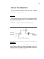
1
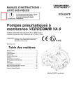
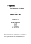
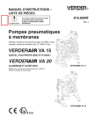
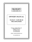
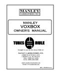
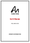
D.W. FEARN
VT-3
Vacuum Tube
Instrument Interface
Operating Instructions
How to Contact us:
Telephone: 610-793-2526
Fax: 610-793-1479
Mail: P.O. Box 57, Pocopson, PA 19366 U.S.A.
Shipping Address: 182 Bragg Hill Road
West Chester, PA 19382 U.S.A.
e-mail: [email protected]
www.dwfearn.com
Ta b l e o f C o n t e n t s
History of the VT-3 ................................................................................ 7
Specifications.......................................................................................... 9
Description..............................................................................................11
Installation ..............................................................................................13
Operation ................................................................................................17
Theory .....................................................................................................21
Maintenance............................................................................................23
List of Illustrations
Rear Panel Controls and Connections ....................................................15
Front Panel Controls and Connections ...................................................15
Block Diagram........................................................................................21
Notice
D.W. Fearn shall not be liable for technical or editorial errors or omissions in this manual, nor
for incidental or consequential damages resulting from the use of this material.
This instruction manual contains information protected by copyright. No part of this guide
may be photocopied or reproduced in any form without prior written consent from D.W. Fearn.
Copyright ©2006 D.W. Fearn & Associates
L I M I T E D 5 -Y E A R WA R R A N T Y
During the warranty period, D.W. Fearn will, at no additional charge, repair or replace defective parts
with new parts.
This warranty does not extend to any VT-3 that has been damaged or rendered defective as a result of
accident, misuse, or abuse; by the use of parts not manufactured or supplied by D.W. Fearn; or by unau-
thorized modification of the VT-3. Vacuum tubes are excluded from the 5-year warranty, but are warranted for a period of 90 days.
Except as expressly set forth in this Warranty, D.W. Fearn makes no other warranties, express or
implied, including any implied warranty of merchantability and fitness for a particular purpose.
7
H i s t o r y o f t h e V T - 3 Va c u u m T u b e D I
As far back as I can remember, taking instruments “direct” has never sounded
very good to me. There always seemed to be a lack of dynamics, and a sterile qual-
ity to sounds recorded with a direct box (or DI).
The first tube DI that we produced was the VT-I/F Instrument Interface. It was
a beautiful piece, in a large, machined-aluminum case that you could drive a truck
over. Unfortunately, the cost of that case made it impossible to build the VT-I/F for
a reasonable price. Only about 75 were ever made, but the owners loved them, and
we kept getting requests for it. After several years of promises to bring out a rackmount version, we finally did so in 2006. The VT-3 is exactly the same as the VTI/F internally, except that we added a switchable high-pass filter and changed tubes
from the 6072A (which we use in all our preamps) to the 6N1P, an excellent-
sounding tube used in our VT-4 Eq and VT-7 Stereo Compressor.
Before beginning the design of the circuit, I spoke to engineers, producers, and
musicians about what they felt was lacking in DI boxes. Almost without exception,
they all said, “It’s got to have tons of headroom.” How much headroom was
enough? I spoke to a number of instrument pickup manufacturers and got an idea
of the peak output level of a variety of instruments. These figures were confirmed
with an oscilloscope placed directly across the output of various electric guitars,
basses, pianos, synthesizers, etc.
The first design goal was to accommodate the full dynamic range of sources
likely to be connected to the VT-3. Secondly, the design had to be quiet. After that,
it was just a matter of designing it to have the type of performance and packaging
that audio professionals have come to expect from our other products.
The decision was made early on that the output of the VT-3 would be at microphone level. Although a line-level output is not difficult to design, it would
increase the cost. Besides, everyone has mic preamps available. Although the VT3 will work with virtually any mic preamp, it was designed to complement the VT1/VT-2 series of preamps.
We tried the first prototype on a solid-body electric guitar, and compared the
sound to several other respected DI boxes. We were astonished at first listen! It
sounded very close to the sound of the guitar through a good vacuum tube amp.
8
This prototype was evaluated by a number of studio friends, who made some
useful suggestions. These suggestions were incorporated into the second prototype, and the VT-3 design was complete. By the way, our evaluators were very,
very reluctant to return the prototype.
Why does the VT-3 sound so good? For one thing, it provides the proper load to
the instrument. This is vital for an unrestricted sound. The frequency response is
flat from 10 cps to 20 kc, with -3 dB points at 0.5 cps and 90 kc. The VT-3 circuit
is very similar to the circuit of the VT-1/VT-2, with a different input design. The
output is identical to the VT-1/VT-2 but operates at a lower level.
The VT-3 has been used on electric and acoustic (with a pickup) guitars, elec-
tric and acoustic (with a pickup) bass, electric pianos, synthesizers, samplers, etc.
and it sounds great on all of them. It will not overload on any instrument, although
when driven hard, the sound becomes fatter. It has enough gain, and it’s quiet
enough, for use with very low level instruments, like finger-picked acoustic gui-
tar.
The lifeless, restricted sound I thought was part of direct recording is gone. The
VT-3 has depth, fullness, dynamics, and excitement while remaining quiet and
under control with any instrument.
Douglas W. Fearn
October 2006
VT-I/F Vacuum Tube Instrument Interface
D.W. FEARN
9
Specifications
(with 200 mV input)
Input
200 mV nominal
unbalanced
Input Load
Impedance
1 megohm minimum
Minimum
Input Level
5 mV nominal
Maximum
Input Level
Gain
Frequency
Response
2.3 volts P-P for
1% THD
-10 dB
+/- 0.2 dB 10 cps to 20 kc
-3 dB @ 0.5 cps and 95 kc
THD + Noise
<0.3% 20 cps to 20 kc
Intermodulation
Distortion
<0.01% SMPTE
Noise
minimum 90 dB below output
(22 cps to 22 kc bandwidth)
Output
Transformer Balanced
(matches 150 ohm input)
Output Level
-30 dBm nominal
Maximum
Output Level
-12 dBm @ 20 cps
Crosstalk
maximum -90 dB @ 20 kc
Power
Requirements
100/120/220 VAC 50/60Hz
25W
Dimensions
19”W x 5.25”H x 10”D
(48.3cm x 13.3cm x 25.4cm)
Weight
10 lbs (6.82 kg)
NOTE: Throughout this manual, frequency is specified in cps (cycles per second) and kc (kilocycles per second). These units correspond
to Hz and kHz. Specifications and price subject to change without notice.
D.W. FEARN
VT-I/F Vacuum Tube Instrument Interface
10
VT-I/F Vacuum Tube Instrument Interface
D.W. FEARN
11
Description
The D.W. Fearn model VT-3 Vacuum Tube DI is designed to provide recording
professionals with a sonically superior method for recording electric and electronic musical instruments by direct injection (DI). Any instrument designed to oper-
ate into a “guitar amp” will work perfectly with the VT-3. Typical instruments
include: electric bass, electric guitar, electric piano, acoustic instruments with a
pickup (piano, acoustic guitar, electric violin, etc.), synthesizers, and samplers.
The VT-3 is a two-channel device that provides the optimum load impedance for
these instruments. It is capable of quality reproduction of a wide range of instrument levels. The unit does not have the limitations of passive transformer-type
DIs, and has greater headroom and warmth when compared to similar solid-state
devices.
It is designed to operate in the professional recording or performing environ-
ment. The output level is “hot” mic level (-30 dBm nominal). The output is transformer-balanced, using a custom transformer built for us by Jensen Transformers,
Inc., and is designed to match 150 ohm professional mic inputs. Top-quality parts
are used throughout. Both the filament and plate power supplies are fully regulated.
The VT-3 is not mass-produced. Each one is hand-made and meticulously tested before shipment to the customer.
D.W. FEARN
VT-I/F Vacuum Tube Instrument Interface
13
Installation
The VT-3 is carefully packed for shipment and should survive all but the most
brutal handling. If there is any damage, keep the shipping material for use during
any claim for damage with the shipper.
Included in the box:
1) The VT-3 DI
2) Line cord
3) This instruction manual
Mounting
The VT-3 is designed to be rack-mounted. In most cases, cooling will not be a
problem, but avoid placing the unit where it is tightly confined. Do not block the
cooling holes on the top. The VT-3 runs cool, cooler, in fact, than many solid-state
devices.
Moderate electrical and magnetic fields in the vicinity of the VT-3 should not
cause any degradation in noise performance, due to the well-shielded construction,
but proximity to devices with motors or large power transformers (i.e. tape
machines or power amps) should be avoided.
Although the vacuum tubes in the VT-3 are selected for minimum microphonic
response, it is a good practice to avoid mounting locations that subject the unit to
very high sound or vibration levels.
REAR PANEL CONNECTIONS (See Figure 1, page 15)
AC (Mains) Power (1)
The VT-3 is designed to operate from 100, 120, or 220-240 volt, 50/60 Hz
power. A recessed slide switch (3) on the back panel allows instant change from
120VAC to 240VAC operation. For 100VAC operation, internal wiring changes
14
are required. The ground pin of the power cord is internally connected to the chas-
sis. This configuration is standard in professional equipment and is required by
most electrical codes. If ground loop hum is detected, a careful check of the studio grounding scheme is needed. The VT-3 is less susceptible to grounding prob-
lems than many studio devices.
The Fuse (2) is a 3AG-type 1 amp for 100/120 VAC operation, and 0.5 amp for
220 volts.
The AC input connector is used with the mating line cord (supplied). For 120
VAC operation, this cord is a Belden 17250 or equivalent.
CONNECTIONS (See Figure 1 and 2, page 15)
The VT-3 has two identical channels, labeled A and B. They may be used indi-
vidually or simultaneously. These instructions apply to either channel.
The musical instrument output connects to the front panel INSTRUMENT input
(6) via a standard 1/4 inch single-conductor (monaural) phone plug. The input is
unbalanced. Since the input cables carry very low level audio, it is important that
well-shielded cables are used. There should be no additional connectors, patch
jacks, switches, etc. between the instrument and the VT-3 inputs. It is important to
keep the input lines as short as possible. Avoid locating the VT-3 where it will be
subjected to high sound levels or excessive vibration (such as on a drum riser).
If desired, the musical instrument may be simultaneously connected to the input
to an external instrument (guitar) amplifier. The AMP jack (7) is a 1/4” single-conductor (monaural) phone jack wired directly in parallel with the INSTRUMENT
jack.
The OUTPUT connectors (5 and 10) are XLR-3 male wired according to AES
standard: pin 1 is ground (shield), pin 2 is “high” or “+,” and pin 3 is “low” or “.” The output is transformer-balanced. The output level is a nominal -30 dBm.
This is somewhat higher in level than a typical microphone.
The back panel of the VT-3 also has XLR output connectors (5) that are wired
in parallel with the front panel XLRs. Signal is present on both the front and rear
VT-I/F Vacuum Tube Instrument Interface
D.W. FEARN
15
connectors at all times. It is not good practice to use both the front and rear con-
nectors at the same time, although it may be possible under some conditions. Both
outputs should feed similar balanced mic inputs. Some loss of quality will result
whenever mic inputs are paralleled.
Fig. 1 VT-3 Rear Panel Controls and Connections
12
9
6
D.W. FEARN
VT-3
Vacuum Tube DI
HPF
HPF
A
B
Mic Level
Out
Instrument
Mic Level
Out
Instrument
|
7
0
Amp
8
Ground
Lift
Amp
Ground
Lift
Power
10
11
Fig. 2 VT-3 Front Panel Controls and Connections
D.W. FEARN
VT-I/F Vacuum Tube Instrument Interface
16
Grounding and Shields
A full discussion of proper studio wiring schemes is beyond the scope of this
manual, but, in general, the shield should be connected to pin 1 of the output connector. The shield should be connected to ground at only one end; however,
although not recommended, the shields can often be connected at both ends without a problem.
VT-I/F Vacuum Tube Instrument Interface
D.W. FEARN
17
O P E R AT I O N
FRONT PANEL CONTROLS (see Figure 2)
Power switch (11)
Primary power is applied to the VT-3 circuits when the Power switch (11) is in
the up position. The amber pilot lamp (12) on the front panel indicates that the unit
is on. It takes about twenty seconds for the VT-3 to start working, but it is suggested that you turn on the power at least five minutes prior to use. The tubes are
often noisy until all the internal elements reach a stable operating temperature.
The GND LIFT switches connect or disconnect pin 1 of the OUTPUT connec-
tors to the unit internal ground. In most situations, the GND LIFT switch (8) will
remain in the down (pin 1 to internal ground) position. In some situations, partic-
ularly when an external instrument amplifier is connected to the AMP jack, a
ground loop may occur. This causes a hum or buzz in the recording equipment.
Placing the GND LIFT switch in the up position may help alleviate this.
HPF switch (9)
The VT-3 has a built-in high-pass filter that will smoothly roll off frequencies
below 100Hz when switched in. This may be useful in some situations where the
source has excessive bass content for the recording.
HUMS AND BUZZES
Unfortunately, it is the nature of high-impedance, unbalanced instrument output
to be highly susceptible to hum and buzz. Some of this is often unavoidable — the
instrument pickup(s) are very sensitive to the omnipresent AC fields in our environment. Experiment with the orientation of the instrument to minimize this
source of noise. Most guitar and bass players will do this automatically, but with
keyboards it may be necessary to rotate and/or move the instrument to find the quietest spot.
18
Fluorescent lights and SCR dimmers are terrible electrical noise generators.
Turn off the fluorescents. If SCR dimmers must be used, they will generally produce the least noise in their full-on (brightest) position.
Another source of these hums and buzzes is ground loops caused by the interconnection of various AC (mains) powered equipment. A properly-wired studio
should not create a ground loop between the VT-3 and the studio equipment, but
often a loop is formed when the VT-3 is connected to an instrument and guitar amp
simultaneously. In this case, use the GND LIFT (8) switch to find the proper position for minimum noise. If the guitar amp has a “Ground” switch, experiment with
it as well. Be sure to try all combinations of all switches.
IMPORTANT
When using the VT-3 with the D.W. Fearn VT-1 or VT-2 Vacuum
Tube Microphone Preamplifier, the VT-1/VT-2 Input switch
should be in the -20 dB position (unless the instrument level is
extremely low). With other preamps, use the input pad and/or
reduce the gain of the preamp.
The VT-3 and the guitar amp (if used) should be on the same electrical circuit
(same circuit breaker or fuse) as the studio equipment to minimize ground loop
potential.
Suggestions
You have chosen to use the VT-3 because of the superior sound it provides. To
gain the maximum benefit from your investment, it is important that you hook up
the VT-3 so that other factors do not adversely affect the sound quality.
VT-I/F Vacuum Tube Instrument Interface
D.W. FEARN
19
1. The VT-3 must be located near the instrument. Ten feet of cable between the
instrument and the VT-3 should be considered the maximum.
2. Use the best quality cables you can. We don’t believe you have to use esoteric wire, but do use good quality, well-shielded cables. The input cable
shielding is particularly important. The output cable should be a standard
balanced mic cable designed for use with low-Z microphones. Gold-contact
phone and XLR connectors are recommended. The length of the output
cable is not critical, but it should not be any longer than necessary.
3. Ideally, there should be no additional cables, connectors, junction boxes,
patch jacks, punch blocks, etc. between the VT-3 output and the VT-1/VT-2
Input.
4. The outputs of the VT-1/VT-2 should be fed directly to the recorder through
the shortest practical lengths of quality cables. Avoid additional cables, con-
nectors, junction boxes, punch blocks, or patch jacks. Use gold contact connectors if possible. Do not go through the mixing console unless you
absolutely need its features for the track you are cutting.
4. If processing (compression, equalization, gating, etc.) is required while
recording the track, insert the processing device after the VT-1/VT-2 and
before the recorder. You may find that far less processing is required when
using the VT-3.
5. Feeding the VT-3 into the studio console will negate some of the benefits of
the VT-3. Use a premium-quality microphone preamplifier (such as our VT-
1/VT-2). Go through the console only if it is absolutely necessary.
D.W. FEARN
VT-I/F Vacuum Tube Instrument Interface
20
21
T H E O RY O F O P E R AT I O N
This circuit description refers to only one channel. Both channels are identical,
sharing only the power supply. (See Figure 3.)
Input section
The INSTRUMENT input jack is fed directly to the grid of the first amplifier
stage, a selected 6N1P. The input impedance is very high (1 megohm) for proper
loading of the musical instrument.
The first stage is capacitively-coupled to the grid of the output stage.
From Instrument
Mic Level Output
to Preamplifier
To Guitar Amp
Figure 3. VT-3 Block Diagram
Output Stage
The output tube is the second section of the 6N1P. It is operated as a cathode
follower, capacitively-coupled to the custom output transformer. A resistive network on the secondary of the transformer provides proper loading and matching to
the input of the external microphone preamplifier.
22
The GND LIFT switch disconnects pin 1 of the OUTPUT connector from the
internal ground when the switch is in the up position.
Power Supplies
Primary power from the AC mains is connected to the VT-3 through a standard
IEC power input connector. The Power switch energizes all power supplies. A
fuse, accessible on the rear panel, protects the VT-3. and a recessed slide switch
provides quick switching between 120VAC and 220-240VAC operation.
The Pilot lamp is a type 1819 bulb, operated far below its rated voltage of 28.
The life of the bulb is lengthened, and the light output is more compatible with
other modern studio equipment.
The power transformer is custom made for the VT-3 and has primary taps for
100, 120, or 220 volt operation.
Filament supply
The power transformer output is rectified by a bridge rectifier and filtered
before being regulated to 12.0 volts by a three-terminal regulator. The negative
output of this supply is grounded. The tube filaments are rated for 6.3 volts; the are
operated in series-parallel at 12.0 volts, which reduces heat dissipation in the filament regulator.
B+ supply
Two separate regulated voltages are required for the plates of the VT-3. The B+
is filtered with long-life, low-leakage computer-grade filter capacitors before
being regulated and extensively bypassed and decoupled. The negative side of the
supply is grounded.
VT-I/F Vacuum Tube Instrument Interface
D.W. FEARN
23
MAINTENANCE
The VT-3 is built with only the highest quality parts and will prove to be
extremely reliable. Vacuum tubes and electrolytic capacitors, however, have a
finite useful life and must be periodically replaced. Typical tube life with average
usage should be at least 5 years. Electrolytic filter capacitors should be good for at
least 10 years.
TOP COVER REMOVAL
Removing the top cover allows access to the vacuum tubes. Twelve 6-32
phillips-head screws must be removed.
Vacuum Tubes
A single 6N1P tube is used in each channel of the VT-3. There can be as much
as a 15 dB difference in noise level among an assortment of tubes, and the tube
used in the VT-3 should be carefully chosen to maintain low noise. Selected lownoise tubes are available from D. W. Fearn.
Tube life is difficult to predict, but it will probably be measured in years.
Catastrophic tube failure is rare with this type of device, but a gradual increase in
noise or distortion, or a reduction in headroom, should indicate the need for
replacement. It is recommended that you periodically perform a quick noise and
distortion check on the VT-3 and compare the results to previous measurements.
Tubes also sometimes develop a microphonic response — they will respond to
ambient noise and vibration. This can be an insidious problem since measurements
in a quiet room will indicate perfect performance. Gently tapping the tube shields
while listening to the output at a normal monitor level should reveal nothing more
than a slight “clank.” On a peak reading meter connected to the VT-3 output, any
D.W. FEARN
VT-I/F Vacuum Tube Instrument Interface
24
microphonic response above -55 dBm is excessive. Replacement is indicated
unless the VT-3 always operates in a quiet and vibration-free environment.
Although you could purchase a batch of 6N1Ps and select the quietest one(s), it
may be cost effective to buy a low-noise tube from the us. See our web site
(www.dwfearn.com) for current prices. We test the tubes in a VT-3 after a burn-in
period and grade them according to noise, microphonic response, and other characteristics. A low-noise tube from us will meet the original VT-3 specifications.
Remember that vacuum tubes may be quite hot during operation. Protect your
fingers during tube replacement. The VT-3 should be turned off before removing
tubes. Allow at least one minute for the filter capacitors to discharge before tube
removal or insertion.
Tubes are made of glass and will break if dropped or even bumped in a critical
area. Handle with care.
Electrolytic Capacitors
The VT-3 is designed and built to last for a long, long time, and it is possible
that some components (e.g. electrolytic capacitors) may reach the end of their life
long before the equipment becomes obsolete. The electrolytic capacitors used in
the VT-3 typically will last at least ten years. If there is a measurable and/or audi-
ble increase in 120 cps noise, the filter capacitors should be suspected. They
should be replaced with new capacitors of equivalent capacitance and voltage rat-
ing, and the replacements should be specified for a minimum ten-year service life.
Electrolytic capacitors are also used as plate decouplers. In choosing a replace-
ment, the same considerations as with the filter capacitors should be followed.
TROUBLESHOOTING
Most problems will be traced to defective vacuum tubes. However, if normal
tests do not easily reveal the problem, feel free to call the factory for assistance. If
you lack access to a qualified service technician with vacuum tube equipment
VT-I/F Vacuum Tube Instrument Interface
D.W. FEARN
25
repair experience, you may return the VT-3 to the factory for repair. Call first,
however, for shipping information.
WARRANTY REPAIR
If the VT-3 should develop a problem during the five-year warranty period, call
the factory for return shipping instructions. We will repair and return your VT-3
quickly. Note that the warranty does not cover vacuum tubes, which must be periodically replaced.
D.W. FEARN
VT-I/F Vacuum Tube Instrument Interface