1
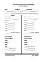
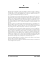
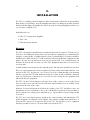
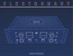
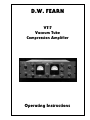
D.W. FEARN
VT-7
Vacuum Tube
Compression Amplifier
Operating Instructions
How to Contact us:
Telephone: 610-793-2526
Fax: 610-793-1479
Mail: P.O. Box 57, Pocopson, PA 19366 U.S.A.
Shipping Address: 182 Bragg Hill Road
West Chester, PA 19382 U.S.A.
e-mail: [email protected]
www.dwfearn.com
D.W. FEARN
VT-7 Compression Amplifier
D.W. FEARN
www.dwfearn.com
H AND - CRAFTED
PROFESSIONAL
RECORDING EQUIPMENT
P.O. Box 57
Pocopson, PA 19366 U.S.A.
Tel: 610-793-2526
Fax: 610-793-1479
Certificate of RoHS Compliance
D.W. Fearn is committed to manufacturing products that are fully-compliant with
the EU RoHS Directive.
The following products are compliant:
VT-1
VT-2
VT-3
VT-4
VT-7
VT-15
LP-1
PDB
This declaration is based on our understanding of the current RoHS Directive and
from information provided by the supplier material declarations with regard to
materials contained in the component that make up our products.
Douglas W. Fearn
President
5
VT-7 Vacuum Tube Compression Amplifier
Final Test Report
Model _______________ Serial Number_______________Mains Voltage ______________
Date ___________________ Tested by ________ VU Calibrated to _______________ dBm
Test Equipment _______________________________________________________________
Channel B
Channel A
Frequency Response:
Frequency Response:
20 cps to 20 kc/s +/- ___________ dB
20 cps to 20 kc/s +/- ___________ dB
THD+Noise:
THD+Noise:
20 cps ______________ %
20 cps ______________ %
200 cps _____________ %
200 cps _____________ %
2 kc/s _______________ %
2 kc/s _______________ %
20 kc/s ______________ %
20 kc/s ______________ %
Noise:
Noise:
______________ dB below +4 dBm out
______________ dB below +4 dBm out
Operational Tests:
Operational Tests:
Compression Range ________
Compression Range ________
Attack ____________________
Attack ____________________
Release __________________
Release __________________
Shape ___________________
Shape ___________________
Link _____________________
Link _____________________
GR Meter ________________
GR Meter ________________
Listening Test ____________
Listening Test ____________
VT-7 Compression Amplifier
D.W. FEARN
7
Table of Contents
Final Test Report ............................................................................3
Warranty .........................................................................................7
History of the VT-7 .........................................................................9
1. Specifications ..........................................................................11
2. Description...............................................................................13
3. Installation .............................................................................15
4. Operation .................................................................................17
5. Theory of Operation ................................................................23
6. Maintenance ...........................................................................25
List of Illustrations
1. Front Panel Controls and Indicators ........................................17
VT-7 Compression Amplifier
D.W. FEARN
8
D.W. Fearn shall not be liable for technical or editorial errors or omissions in this
manual, nor for incidental or consequential damages resulting from the use of this
material.
This instruction manual contains information protected by copyright. No part of this
manual may be photocopied or reproduced in any form without prior written consent
from D.W. Fearn.
Copyright ©2005 D.W. Fearn & Associates
D.W. FEARN
VT-7 Compression Amplifier
9
Limited 5-Year Warranty
During the warranty period, D.W. Fearn will, at no additional charge, repair or replace
defective parts with new parts.
This warranty does not extend to any VT-7 that has been damaged or rendered
defective as a result of accident, misuse, or abuse; by the use of parts not manufactured or supplied by D.W. Fearn; or by unauthorized modification of the VT-7.
Vacuum tubes are excepted from the 5-year warranty, but are warranted for 90 days
from date of purchase.
Except as expressly set forth in this Warranty, D.W. Fearn makes no other warranties, express or implied, including any implied warranty of merchantability and fitness for a particular purpose.
VT-7 Compression Amplifier
D.W. FEARN
11
History of the VT-7 Compression Amplifier
Compression (or limiting) is sometimes seen as a necessary evil in the recording process.
Often it is used to compensate for less than optimum performance or recording technique.
However, when used appropriately, there is no question that good-sounding compression can
add loudness, power, and improved impact to a recording.
Over many years of recording, I have had the opportunity to use and sometimes own some
of the best compressors in the world. For the D.W. Fearn line of products, a compressor was
obviously important. I began the search for the ultimate compressor design in 1995 and it
wasn’t until 2004 that I developed the sound I was looking for.
There are several ways to achieve compression, and all have their advantages and disadvantages. The earliest, and still one of the best, designs uses the characteristic of vacuum tubes
that allows their gain to be varied by changing the grid bias. Only certain tube types are
appropriate for this (the variable-mu or remote cut-off types), and none are currently being
manufactured. Since I want my products to be used for a long, long time, I could not manufacture a product that used tubes that were increasingly rare.
Another excellent approach uses a photoresistor illuminated by a light source to vary the gain
of an amplifier. This method was pioneered by Teletronics/Universal Audio in the LA-2. Many
LA-2s were built over the years, and more recently there have been several new versions of
this classic circuit. The world has a good supply of old and new LA-2-style compressors, and
although I did some experimenting with this circuit, I felt that there were enough of them and
I didn’t need to add another. Also, this design lacks the versatility I thought was necessary.
A more modern approach uses a voltage-controlled amplifier (VCA), which is quite versatile
and can combine several additional functions (de-essing, gating, etc.) in one simple unit.
However, I was never satisfied with the sound of VCA compressors and did not consider that
design for my use.
I experimented with a few off-the-wall approaches, but was not convinced that these designs
would really work to my standards.
Another approach, not often used, utilizes a pulse-width modulator to control the duty-cycle
of a gain reduction element. This approach has several advantages, including the ability to
offer a wide range of adjustment. In the VT-7, a solid-state pulse-width modulator controls a
special shunt element in the audio path to control the gain. Since no audio passes through
the element, there is no added distortion or other degradation of the sound. That’s the simple part. Much more complex is the surrounding circuitry that provides precision control of
the element in a way that conforms to what I wanted to hear.
Because the element is well-isolated from the vacuum tube circuitry before and after it, the
effect on the audio is entirely linear. It does not introduce any measurable distortion. And it
passes my test for sonic superiority.
The vacuum tube audio path uses circuitry developed for the D.W. Fearn VT-4 LC Equalizer.
In some of the circuit, entirely new designs were needed. The VT-7 uses a combination of
6072A and 6N1P tubes and has the basic sound of all my products.
VT-7 Compression Amplifier
D.W. FEARN
12
A look inside the VT-7 reveals a very full box with several densely-packed circuit boards for
the gain control driver circuitry, interspersed with eight vacuum tubes. Because of the very
high frequencies involved in the control circuitry, there are many surface-mount (SMT) components. Thus, the VT-7 is a combination of the latest technology, where needed, with a classic great-sounding vacuum tube audio path.
The VT-7 was designed from the beginning to be a stereo compressor. The two channels can
be used separately or linked together for stereo.
So what does the VT-7 sound like? In many respects, it is like the classic vacuum tube compressors with the same musical sound. I have always believed that for most applications the
compression characteristics that sound best are those that approximate the natural compression inherent in our hearing. The VT-7 has this kind of natural-sounding compression that
sounds just right to me.
The ultimate test for all my products is this: Would I use it in preference to any other product out there, old or new? The VT-7 passes this test.
There are not a lot of controls on the VT-7. Basically, there is just a knob to control the
amount of compression (Threshold), the amount of gain, the attack and release times, and a
knob that smoothly varies the compression characteristic from a “softer” to a “harder”
sound. At first, some users may find the controls do not have the range of adjustment that
they are used to in more heavy-handed limiters. However, true to philosophy of design in all
my products, the VT-7 is intended to take good sound and make it sound great. Although its
effect can be made to sound obvious, I like the way the VT-7 sounds like what a really good
engineer would do if he had excellent taste and infinitely fast hands on a fader. In other
words, the VT-7 controls the levels without drawing attention to itself. To me, it just sounds
right.
Douglas W. Fearn
November 2004
D.W. FEARN
VT-7 Compression Amplifier
13
1.
S P E C I F I C AT I O N S
Input
Input Load
Impedance
Nominal Input
Level
Maximum Input
Level @ 20 cps
Gain
Frequency
Response
THD + Noise
Signal to
Noise Ratio
Output
Output source impedance
Maximum
Output Level
Gain Reduction Range
Power
Requirements
Dimensions
Weight
Shipping Weight:
600 ohm source (nominal)
balanced or unbalanced
32k ohms, transformer
balanced bridging
+4 dBm
+25 dBm
unity to +15dB
± 0.2 dB 20 cps to 20 kc
± 0.5 dB 11 cps to 28 kc
-3 dB @ 0.5 cps & 65 kc
<0.05% 20 cps to 20 kc
78 dB minimum
low-Z, transformer balanced
115 ohms
+22 dBm into bridging input
balanced or unbalanced
0 to 20dB
100, 120, or 220 VAC
50/60Hz, 85 W
19” (48.26cm) W
5.25” (13.34cm) H
13” (22.9cm) D
22 lbs (9.55 kg)
28 lbs (12.27 kg)
(measurements are made with +4dBm input and output, no compression, into a bridging load)
VT-7 Compression Amplifier
D.W. FEARN
15
2.
DESCRIPTION
The Model VT-7 Vacuum Tube Compression Amplifier is designed to provide recording professionals with a sonically superior signal processing device. It is typically used in sound
recording studios for processing individual tracks or, when the channels are linked, as a
stereo compressor. The inputs and outputs are at line level.
The VT-7 in many ways recreates the sound of the classic tube compressors of the 1960s, but
using modern gain control circuitry. The audio path is entirely Class-A triode vacuum tubes,
similar to classic designs but updated with improved modern passive components and computer-aided circuit optimization. Because of the unique qualities of vacuum tubes, the VT-7
has a clarity, transparency, and warmth that solid state compressors lack. Its modern design
and construction allows the VT-7 to exceed the performance of vintage vacuum tube compressors.
The VT-7 is capable of over 30dB of gain reduction, but all units above serial number 19 are
limited to 15dB of compression to provide greater resolution in the Threshold control for setting moderate amounts of compression. The VT-7 can be special-ordered with the full 30dB
range. Although a VT-7 could be modified after construction, it is rather involved.
It is designed for use in the professional recording environment. It accepts a low impedance
(600 ohm nominal source impedance) balanced or unbalanced line level (nominal +4dBm)
signal. It features two independent channels, which can be linked to provide precise gain
reduction tracking of a stereo signal. There are controls for compression threshold, gain,
attack and release times, and compression curve. Additional controls are used to link the two
channels and to switch the true VU meter between measuring gain reduction and output
level. It is built to sound great for a long time, with top quality parts used throughout; the output transformers and many other components are custom-made for the VT-7.
All five power supplies (filament, B+, and three voltages for the solid-state control circuitry
and meter amp) are solid state and fully regulated.
The VT-7 is not mass-produced. Each one is hand-made and meticulously tested and listened
to before shipment to the customer.
VT-7 Compression Amplifier
D.W. FEARN
16
D.W. FEARN
VT-7 Compression Amplifier
17
3.
I N S TA L L AT I O N
The VT-7 is carefully packed for shipment and it should survive all but the most brutal handling. If there is any damage, keep the shipping material for use during any possible claim for
damage with the shipper. You might also want to keep the box and packaging material in case
you ever have to ship the VT-7.
Included in the box:
1) The VT-7 Compression Amplifier
2) Line cord
3) This instruction manual
Mounting
The VT-7 is designed for installation in a standard 19 inch rack. It requires 5.25 inches of vertical space, but additional spacing between it and adjacent equipment is recommended for
adequate cooling. Ideally, a ventilated panel at least 1 rack unit high (1.25 inches) should be
installed above and below the VT-7 (and around any other heat producing equipment for that
matter). Be sure the top and bottom vent slots are not blocked. It is essential that air can
flow into the bottom and out of the top of the VT-7. Equipment that runs cool can last for a
very long time.
A small (45mm) fan is mounted on the right side panel. The fan outlet should not be blocked.
There are eight vacuum tubes and seven printed circuit boards loaded with solid-state components in the VT-7. It generates a lot of heat. You need to think through your mounting
scheme to provide the VT-7 with sufficient air flow for cooling. It will eventually be damaged
if the top and bottom cooling slots are covered. Forced air cooling in your equipment rack
will benefit all your equipment.
The VT-7 can also be used without a rack, placed on a table, counter, or even on the floor if
there is room for air to enter the bottom of the unit. Optional rubber feet are available, when
requested at the time of the order.
Moderate electrical and magnetic fields in the vicinity of the VT-7 should not cause any
degradation in noise performance, due to the well-shielded construction, but proximity to
devices with motors or large power transformers (i.e. tape machines or power amps) should
be avoided.
The VT-7 uses some high frequency signals in the control circuitry and although the VT-7
itself is designed to be immune to these signals, other sensitive equipment mounted above or
below the VT-7 may not be designed as well as the VT-7. You may have to move equipment
that has poor RFI rejection to a location farther away from the VT-7.
VT-7 Compression Amplifier
D.W. FEARN
18
Power
The VT-7 is designed to operate from 100, 120, or 220-240 volt, 50/60 Hz power. The unit
will be shipped for the voltage specified in the order, but may be changed in the field if necessary. (See the Maintenance section for detailed instructions on changing the primary voltage). The ground pin of the power cord is internally connected to the chassis. This configuration is standard in professional equipment and is required by most electrical codes. A
grounding screw is provided on the back panel for installations that use separate chassis
grounding. If ground loop hum is detected, a careful check of the studio grounding scheme
is needed. The VT-7 is less susceptible to grounding problems than many studio devices.
Connections
The INPUT connectors are XLR-3 females wired with pin 1 ground, pin 2 “+” or “high,” and
pin 3 “-” or “low.” The input matches 600 ohm (nominal) line level (+4dBm nominal) balanced or unbalanced signals. The input uses a top-quality Jensen line bridging transformer.
The OUTPUT connectors are XLR-3 male wired with pin 1 ground, pin 2 “+” or “high,” and
pin 3 “-” or “low.” The VT-7 is optimized for feeding balanced bridging inputs. (Virtually all
modern audio equipment has bridging inputs.) The output is transformer-balanced.
The “GND” terminal is for use when an external grounding scheme is utilized.
The Fuse is a 5x20mm-type slow-blow 2 amp for 100 or 120 VAC operation, and 1 amp for
220-240 volts.
The AC input connector is used with the mating line cord (supplied). For 120 VAC operation,
this cord is a Belden 17250 or equivalent.
The unit does not utilize any RFI filtering, and no RFI has been experienced, even when the
VT-7 is operated in close proximity to AM, FM, and TV broadcast transmitters.
Input and Output Connections
Gold-plated XLR connectors are used for inputs and outputs. The input connectors are
female and the outputs male.
All connectors are wired according to AES standard: pin 1 is ground (shield), pin 2 is “high”
or “+,” and pin 3 is “low” or “-.” A positive voltage on pin 2 of the input will result in a positive voltage on pin 2 of the output.
Grounding and Shields
A full discussion of proper studio wiring schemes is beyond the scope of this manual, but, in
general, whether the shield is connected to pin 1 of the output connector depends on the
standard in your studio. The shield should be connected to ground at only one end of the output cable; however, although not recommended, the shields can often be connected at both
ends without a problem.
D.W. FEARN
VT-7 Compression Amplifier
19
4.
O P E R AT I O N
Input
Since the input cable will be carrying high quality audio, it is important that a well-shielded
cable is used. You should strive to minimize the number connectors, patch jacks, switches,
etc. between the source and the VT-7 input.
Output
The output of the VT-7 is line level, transformer balanced. Note that vacuum tube equipment
is more sensitive to load impedance than solid state units. The VT-7 design was optimized for
feeding a balanced bridging input (20k ohms or greater). When feeding a 600 ohm load,
there may be a slight degradation of some of the specifications. In modern studio equipment, bridging line inputs are universal. If the device being fed by the VT-7 has an input termination switch, that switch should be in the “off” position.
The VT-7 can feed balanced or unbalanced inputs with no need for any modification in output wiring. Either pin 2 or 3 can be grounded, although pin 2 is normally used as the ”hot”
and pin 3 grounded in unbalanced configurations.
Threshold
Attack
Gain
Release
Pilot lamp
Harder/Softer
Link
Meter switch
Figure 2. VT-7 front panel controls and indicators
VT-7 Compression Amplifier
D.W. FEARN
20
CONTROLS (see Figure 2.)
Threshold The Threshold control adjusts the point where compression begins. With the con-
trol all the way down, there is no compression and the VT-7 operates as a straight amplifier.
As the control is turned clockwise, the amount of compression increases. This can be monitored on the VU meter (in the GR position), or by ear.
Gain Whenever compression is applied, the signal is reduced in level by the amount of gain
reduction. The Gain control allows you to make up the lost gain as necessary. At the full
counter-clockwise position, the gain of the VT-7 (with no compression) is about -3dB. The
maximum gain available is about 15dB.
Attack This control adjusts the time it takes the VT-7 gain reduction circuitry to react to a
signal. It might seem that the faster the attack time, the better, but very fast attack times will
result in significant distortion on material with a lot of low frequency content (this is true of
all compressors). As the control is turned clockwise, the attack time becomes longer. Often
with percussive sounds it is advantageous to have fairly long attack times to allow the initial
transient of the sound to pass through the VT-7 without gain reduction. Experiment with the
Attack control on percussive material to see how it changes the sound. Generally speaking,
a fast attack time is best when complete control of the maximum instantaneous level is
required. This might be desirable to protect a digital input from overload. However, a more
natural sound is usually obtained with a slightly slower attack time. Long attack times can be
useful as an effect, adding power to percussive instruments.
Release The Release control adjusts how long it takes for the gain to return to normal after
a sound ceases (or drops in level). Fast release times add more energy to the sound, but can
add distortion to low frequency sounds. (This is true of all compressors.) A fast release time
adds density to the sound, often with the compression becoming more obvious. Long release
times make the compression less obvious and more natural, but can “punch holes” in the
lower level audio under certain conditions of high percussive levels.
Harder/Softer This control adjusts the nature of the compression curve. Toward the
“Harder” end of the control, the compression ratio is higher and the levels more tightly controlled. At the “Softer” end, the compression ratio is lower and the compression is more gentle. This is not merely a ratio control, however, as other parameters also change as the control is adjusted. More than any other control, this one needs to be adjusted by ear. This control interacts with the Threshold, Attack, and Release controls, so after changing the
Softer/Harder control, you should experiment with others to obtain the effect you desire. Its
technical operation is complicated to explain, so it is much easier to understand it simply by
experimenting.
Separate/Link/Link HPF This is a three-position switch that links the two channels togeth-
er for stereo operation. In the Separate position, the two channels operate completely independently, and can be used on totally different sources without any interaction. In the Link
position, the two channels track each other precisely, so that the stereo image will remain
constant even if one channel has much more level than the other. In the Link HPF position,
a high-pass (low cut) filter is inserted in the sidechain. This makes the compression less basssensitive and may be useful on mixes that have a very heavy bass content. It will reduce
“pumping” of the mix from bass or bass drum hits, and increase the amount of low-end in the
mix. The HPF operates on both channels, in a linked configuration. The roll-off of bass sensitivity is a very gentle curve (about 6dB per octave) and has little effect above 150Hz.
D.W. FEARN
VT-7 Compression Amplifier
21
You can run a stereo signal with the switch in the Separate position for an effect. On a stereo
pair such as a piano or other sub-mix stereo source, the image will tend to shift from left to
right as the signal becomes louder in one channel compared to the other. This would be disconcerting on a stereo bus, but it could be interesting on individual stereo tracks.
With very fast Attack and/or Release times, low-frequency distortion can often be reduced
significantly using the Link HPF position.
When operating in the Link or Link HPF positions, only the left
side (Channel A) controls are operative. The right channel (B)
controls will have no effect on the operation. The only exception
is the Gain control, which will still adjust the level of the B channel in the Link position.
Meter Switch The VU meter can be switched to read either output (“VU”) or gain reduction
(“GR”). In the VU position, the meter will indicate the actual output level of the VT-7. The
“0” VU mark indicates +4dBm output
In the “GR” position, the meter indicates the amount of gain reduction (compression), in dB.
With no compression, the meter will rest at the “0” VU mark. As compression increases, the
meter will move more to the left. The meter reading indicates the average amount of compression. The precise calibration of the no-signal 0VU indication may drift slightly as the VT7 warms up, and change somewhat over time as various components age. This does not affect
the sound of the VT-7 or the gain reduction range. There is a calibration control to set the
0VU indication but it is not something that a non-technical user should adjust.
The VU meter will always indicate an average amount of level or gain reduction, not the peak
value. This is a true VU meter, and conforms to ASA Standard C16.5-1954. The VT-7 is capable of a wider range of gain reduction than a standard VU meter can accurately display, so it
is possible that the reading could be fully to the left end of the scale (greater than 20dB). This
will cause no harm to the VT-7, although it is an extreme amount of compression.
Like all true VU meters, the reading is an average and does not indicate the peak level, either
in output nor in gain reduction.
Pilot light This yellow lamp lights whenever the VT-7 is turned on. The VU meters are also
illuminated.
Rear Panel Controls
Power switch Primary power is applied to the VT-7 circuits when the rear panel power
switch is in the “on” position (|). This switch is directly below the AC input connector.
Mains voltage selector This two-position switch is set to the appropriate mains power volt-
age in the location where the VT-7 is used. The only active positions are the “115” and “230”
positions. The “230” volt position will properly accommodate any mains voltage from 220 to
240 volts nominal. See the Maintenance section for instructions on changing the voltage.
VT-7 Compression Amplifier
D.W. FEARN
22
For 100 volt operation, internal wiring changes must be made. Contact the factory if this
becomes necessary.
Units ordered for 100 volt operation will be wired for that voltage only.
Fuse The center part of the voltage selector is a fuseholder. For 100 and 120 volt operation,
the fuse is 2 amps. For 240 volt operation it is 1 amp. See the Maintenance section for fuse
replacement information.
Bench Test
If desired, test the VT-7 before installation. The source generator should be set to +4dBm,
600 ohms impedance, balanced, and the output should feed a balanced bridging input of the
audio analyzer. Measured bandwidth should be 20 cps to 20 kc to obtain the same readings
as the factory test results. Compare your measurements with the test data supplied with VT7. Keep the results for comparison in future maintenance tests.
Initial Set-Up
The VT-7 should be installed as detailed in the Installation section. With the outputs connected to an appropriate destination (typically to audio recorder inputs or as a mixer insert), configure the studio to monitor the VT-7 output. Apply power and wait about twenty seconds for
the tube filaments to get up to temperature. Check for hum, buzz, or other noise. For the first
few minutes after a cold start it is not unusual for the VT-7 to produce hiss, pops, and microphonic “clanks” as the internal elements of the tubes expand from the heat. Correct any
ground loop problems before proceeding.
The controls should be set as follows.
• Power (back panel) . . . . . . . . . . . . . On
• Threshold . . . . . . . . . . . . . . . . . . . . . . 9 o’clock
• Gain . . . . . . . . . . . . . . . . . . . . . . . . . . 9 o’clock
• Attack . . . . . . . . . . . . . . . . . . . . . . . . 1 o’clock
• Release . . . . . . . . . . . . . . . . . . . . . . . 9 o’clock
• Softer/Harder . . . . . . . . . . . . . . . . . . mid-point
• Link/Separate . . . . . . . . . . . . . . . . . . Separate
The best indication of proper operation of the VT-7 is how it sounds. This compressor has a
wide operating range and many different settings can provide a wide variety of effects.
Be certain that the output level of the VT-7 is appropriate for the device connected to the output. +4 dBm is the accepted standard level for all professional recording equipment. Some
older equipment may be designed for 0 dBm or +8 dBm, either of which can be easily accommodated by the VT-7.
D.W. FEARN
VT-7 Compression Amplifier
23
Semi-professional equipment frequently uses a reference level of -10 dBv (roughly 14 dB
lower than pro equipment). Although the VT-7 can feed the unbalanced, -10 dBv inputs of
semi-pro gear with no difficulty, the VT-7 VU meter will have to be recalibrated in order to be
useful. (See Section 6 - Maintenance.)
Use your ears to find the setting that sounds best to you for any given sound.
SUGGESTIONS:
You have chosen to use the VT-7 because of the superior sound it provides. To gain the max
imum benefit from your investment, it is important that you hook up the VT-7 so that other
factors do not adversely affect the sound quality.
Except for extremely short Attack and Release times, the VT-7 will provide quality sound with
any settings. But like any instrument, you will find the best adjustment of the controls by
experimenting. The starting adjustments listed above will get you started. Now play with the
controls to find the sound that fits your project perfectly.
VT-7 Compression Amplifier
D.W. FEARN
25
5.
T H E O RY O F O P E R AT I O N
Input section
Line level (low source impedance, balanced, +4 dBm nominal) audio enters through the XLR3 female INPUT connector to a bridging input transformer. The load imposed on the source
is 32k ohms and is constant regardless of the frequency.
Input transformer
The input transformer is made by Jensen Transformers, Inc. and represents the state of the
art in transformer design. It exhibits extremely flat frequency response, low phase shift,
excellent square wave response, low distortion, and high noise immunity. The secondary of
is connected directly to the grid of the first amplifier stage.
Input Amplifier
First stage
The first stage is a 6N1P configured as a Class A voltage amplifier with a gain of approximately 20. Negative feedback from the plate of the second stage reduces distortion, flattens the
frequency response, and makes the gain of the first two stages less dependent on individual
vacuum tube characteristics.
Second stage
The output of the first stage is coupled to the grid of the second stage through a polpropylene
capacitor. This stage operates as a Class A voltage amplifier with a gain of approximately 15.
Output Stage
The output stage operates as a cathode follower, presenting a comparatively low output
impedance (approximately 450 ohms). The cathode output is coupled through a polypropylene capacitor to the Pulse Width Modulator board.
Pulse Width Modulator
These boards, mounted underneath the chassis, contains the pulse generation and control
circuitry, and the gain reduction element. The loss through the board is about 20dB with no
gain reduction, rising to about 50dB with maximum gain reduction (30dB standard on serial numbers 19 and above). A second pair of printed circuit boards on the top of the chassis
shapes the audio signal for the PWM circuit.
Output Amplifier
First stage
The first stage is a 6072A configured as a Class A voltage amplifier with a gain of approximately 30. Negative feedback from the plate of the second stage reduces distortion, flattens
the frequency response, and makes the gain of the first two stages less dependent on individual vacuum tube characteristics.
VT-7 Compression Amplifier
D.W. FEARN
26
Second stage
The output of the first stage is coupled to the grid of the second stage through a polypropylene capacitor. This stage operates as a Class A voltage amplifier with a gain of approximately 20.
Output Stage
The output stage operates as a cathode follower, followed by a custom output transformer
built for D.W. Fearn by Jensen Transformers, Inc. The output impedance is 115 ohms.
Meter and Meter Amplifier
Two-stage IC operational amplifiers are used to isolate the VU meters from the VT-7 outputs.
An output sample is derived from the primary of the output transformer. The VU meter
amplifiers are constructed on the printed circuit board that also contains the Link/Link HPF
circuitry. It is mounted above the main chassis. The meter calibrations set with a 20-turn
trimmer potentiometer. Reference level (0 VU) can be set from -20 to over +20dBm.
The meter can monitor gain reduction in the “GR” position. The meter is driven by a precision circuit that provides exact tracking with the actual amount of gain reduction. The meter
“0” adjustments are on the PWM boards.
The level indictor is a custom true VU meter conforming to ASA Standard C16.5-1954.
Power Supplies
Primary power from the AC mains is connected to the VT-7 through a standard IEC power
input connector with an integrated power switch. The Power switch energizes all five power
supplies. A mains voltage selector switch on the back panel allows the primary voltage of the
VT-7 to be easily changed in the field.
A fuse protects the VT-7. The Pilot lamp is a type 1819 bulb, operated far below its rated voltage of 28. The life of the bulb is lengthened, and the light output is more compatible with
other modern studio equipment. The power transformer is a toroidal unit custom-made for
the VT-7 and has primary taps for 100, 120, or 220-240 volt operation.
Filament Supply
The power transformer output is rectified by a bridge rectifier and filtered before being regulated, The output of this supply is 12 volts.
Low-voltage Supplies
This supply provides +15, -15, and +5 volts for the solid-state circuitry in the Pulse Width
Modulator.
B+ Supply
Eight separate regulated voltages are required for the plates of the VT-7. The B+ is filtered
with long-life, low-leakage, computer-grade filter capacitors before being regulated and extensively bypassed and decoupled. The negative side of the supply is grounded.
D.W. FEARN
VT-7 Compression Amplifier
27
6.
MAINTENANCE
The VT-7 is built with only the highest quality parts and will prove to be extremely reliable.
Vacuum tubes and electrolytic capacitors, however, have a finite useful life and must be
replaced eventually.
Top/Bottom Cover Removal
Removing the top cover allows access to the vacuum tubes and some of the calibration controls. The top cover allows access to the VU meter calibration controls. Sixteen 6-32 phillipshead screws must be removed. When replacing the cover, position it so that the slotted ventilation holes are over the tubes (towards the back on the VT-7).
CAUTION! With the top or bottom covers removed, voltages of up to
400 are exposed. These voltages can be very dangerous, even lethal in
some circumstances. Only persons with experience with high voltage
vacuum tube equipment adjustment and repair should operate the VT-7
with either the top or bottom covers removed!
Vacuum Tubes
Eight tubes are used in the VT-7. Six are 6N1P and two are 6072A. There can be as much
as a 15 dB difference in noise level among an assortment of tubes, and the 6072A tubes used
should be carefully chosen to maintain low noise. Selected low-noise tubes are available from
D. W. Fearn. The 6N1P tubes are far less critical and almost any quality off-the-shelf tube will
perform satisfactorily.
Tube life is difficult to predict, but it will probably be measured in years. Catastrophic tube
failure is rare with this type of device, but a gradual increase in noise, microphonics, distortion, or a reduction in headroom, should indicate the need for replacement. It is recommended that you periodically perform a quick noise and distortion check on the VT-7 and compare
the results to previous measurements.
Tubes also sometimes develop a microphonic response — they will respond to ambient noise
and vibration. This can be an insidious problem since measurements in a quiet room will indicate perfect performance. Gently tapping the tube shields while listening to the output at a
normal monitor level should reveal nothing more than a slight “clank.” On a peak-reading
meter connected to the VT-7 output, with unity gain, any microphonic response above -55
dBm is excessive. Replacement is indicated unless the VT-7 always operates in a quiet and
vibration-free environment.
VT-7 Compression Amplifier
D.W. FEARN
28
Although you could purchase a batch of 6072A tubes and select the quietest one(s), it may
be cost effective to buy a low-noise tube from the us. Current prices are $76.00 for a selected low-noise 6072A, and $20.00 for a tested 6N1P. (See www.dwfearn.com for the latest
prices.) We test the tubes in a VT-7 after a burn-in period and grade them according to noise,
microphonic response, distortion, and other characteristics. A low-noise tube from us will
meet the original VT-7 specifications.
Remember that vacuum tubes may be quite hot during operation. Protect your fingers during tube replacement. The VT-7 should be turned off and the power cord disconnected before
removing the top cover. Allow at least one minute for the filter capacitors to discharge before
tube removal or insertion. Tubes are made of glass and will break if dropped or even bumped
in a critical area. Handle with care.
Electrolytic Capacitors
The VT-7 is designed and built to last for a long, long time, and it is possible that some components (e.g. electrolytic capacitors) may reach the end of their life long before the equipment becomes obsolete. The electrolytic capacitors used in the VT-7 typically will last at least
twenty years. If there is a measurable and/or audible increase in 120Hz noise (100Hz when
the mains frequency is 50Hz), the filter capacitors should be suspected. They should be
replaced with new capacitors of equivalent capacitance and voltage rating, and the replacements should be specified for a minimum ten-year service life.
Electrolytic capacitors are also used as decouplers. In choosing a replacement, the same
considerations as with the filter capacitors should be followed.
VU Meter Calibration
Output Meter
The meter amplifier circuit is stable and re-adjustment of the meter calibration is not normally required. If the output reference level needs to be changed, here is the procedure:
1. Remove the VT-7 top cover.
2. Terminate the output in the same impedance as the VT-7 will normally be feeding.
This will almost always be a high-impedance bridging termination of 20k ohms or
more.
3. Apply AC power. Allow at least a fifteen minute warm-up. Feed a 1 kc tone at +4 dBm
into the VT-7 input.
4. Measure the output and set the Gain control for +4 dBm (or whatever reference is
desired).
5. Set the Meter Calibration trimmer potentiometers for 0 VU on the VT-7 meter(s). Be
sure the meter is on the “VU” position. This control is a 20-turn pot so the adjustment is easy. A small screwdriver or alignment tool is necessary. The controls are
located on the relay/meter amplifier printed circuit board on the top center of the
chassis. Make sure you have located the proper trimpot; there are other trimpots in
the vicinity that should not be touched.
6. Replace the top cover. Be sure the ventilation slots are over the tubes (towards the
back).
D.W. FEARN
VT-7 Compression Amplifier
29
Gain Reduction meter calibration
The adjustments for the VU meter “0” calibration in the “GR” position are located on the
PWM board. Contact the factory for complete adjustment instructions. Note that the meter
calibration can be off but the VT-7 will continue to operate normally otherwise. Some drifting of this adjustment is normal, and the reading will change as the VT-7 warms up over a
period of an hour or so.
Alignment
There are many alignment adjustments in the VT-7, many of which that require test equipment that is more sophisticated than is available in many studios. Notably, an oscilloscope
with a calibrated time base that can accurately resolve 40nS is required.
The circuitry of the VT-7 is quite stable and routine alignment is usually not required.
If the VT-7 requires alignment, contact the factory for detailed instructions.
Troubleshooting
Most problems will be traced to defective vacuum tubes. However, if normal tests do not easily reveal the problem, feel free to call the factory for assistance. If you lack access to a qualified service technician with vacuum tube equipment repair experience, you may return the
VT-7 to the factory for repair. Call first, however, for shipping information.
Warranty Repair
If the VT-7 should develop a problem during the five-year warranty period, call the factory for
return shipping instructions. We will repair and return your VT-7 quickly. Note that the warranty does not cover vacuum tubes, which must be periodically replaced.
VT-7 Compression Amplifier
D.W. FEARN