1
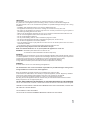
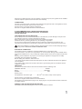
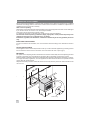
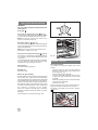
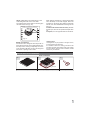
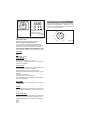
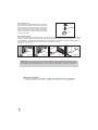
AU GAS BUILT-IN OVEN installation and operating instructions Model No's OWNER'S HANDBOOK NOTE TO INSTALLER: LEAVE THE OWNERS GUIDE MANUAL WITH THE APPLIANCE. (Keep For Future Reference) GENERAL INFORMATION ENVIRONMENTAL WARNING Waste packaging Do not throw the packaging of your appliance into the dustbin, but pick out the different materials (for instance foil, paperboard, polystyrene) according to the local rules for rubbish elimination. This appliance must only be used for the purpose of domestic cooking. RECORD HERE FOR EASY REFERENCE Model Serial Number Colour Installation Date Dealer's Name and Address Environmental protection advice All the materials used are environmentally compatible and recyclable.Please make your contribution to conserving the environment by using the separate waste collection channels available. WARNING Remember ovens get hot: some parts naturally become very hot, notably the glass oven door and the protective strip. KEEP CHILDREN AWAY FROM Oven AT ALL TIMES AND WARN THEM ABOUT THE DANGER. When connecting or using appliances connected to a plug near your oven KEEP THE MAINS CABLE FAR FROM HOT SURFACES OF THE OVEN. WHEN YOU CALL FOR SERVICE When you call for service or order parts for your unit, be sure to give: 1. 2. 3. 4. 5. MODEL SERIAL NUMBER COLOUR PART NAME and/or description of problem YOUR FULL NAME, ADDRESS, and HOME TELEPHONE NUMBER and BUSINESS TELEPHONE NUMBER IF APPROPRIATE. Oven's ratings and serial number are written on the data plate (A) and (B) sealed inside the front of the oven. Front oven (B) Serial number (A) Data plate Servicing shall be carried out only by authorised personnel. GENERAL WARNINGS Read carefully all the instructions contained in this booklet. It provides you with important information regarding the safe installation, use and maintenance of the appliance as well as useful advice for getting the best out of your oven. Keep this booklet in a safe place for future reference. The manufacturer pays particular attention when printing its instruction manual however misprints may occur. If the texts are unclear, please contact the service centre for explanations. WARNING: Before using the appliance, do not forget to remove the protecting parts of the appliance. After removing the packing, check that the appliance is not damaged in any way. Be careful not to leave the packing materials (plastic sheeting, expanded polystyrene etc.) in reach of children, as they A can be dangerous. IMPORTANT: do not use the oven door handle to move the appliance, such as when removing it from the packaging. 2 IMPORTANT This appliance must be used exclusively for cooking food and for no other purpose. Any other use of the appliance (such as heating a room) is incorrect and therefore dangerous. The manufacturer can not be considered responsible for possible damages arising from a wrong installation. - Installation and maintenance have to be done by qualified staff only. - The appliance should only be used for the cooking of food and not for any other use. - The safety of this appliance is assured only when it is correctly connected to a good system of previewed grounding, like from the norms. - When in use the appliance becomes very hot. Do not touch the heated elements inside the oven. - Do not touch the appliance with humid or wet hands or feet. - Do not use the appliance barefoot. - Do not pull the feeding cable in order to detach the plug from socket. - Do not leave the apparatus exposed to atmospheric agents (rain, sun and so on). - Do not allow the appliance to be used by children. - Dont let children sit down or play with the oven door. Do not use the drop down door as a stool to reach above cabinets. - Care should be taken to avoid touching heating elements inside the oven. Do not place heavy objects on the oven door when it is open. Make sure that the knobs are on 0 (closed) when the appliance is not in use. WARNING - Accessible parts will become hot when in use. To avoid burns and scalds children should be kept away. WARNING This appliance is not intended for use by persons (including children) with reduced physical, sensory or mental capabilities, or lack of experience and knowledge, unless they have been given supervision or instruction concerning use of the appliance by a person responsible for their safety. Children should be supervised to ensure that they do not play with the appliance. Young children and infirm persons should not be left unsupervised in the vicinity. WARNING A steam cleaner is not to be used cleaning this appliances. The manufacturer can not be considered responsible for possible damages arising from a wrong installation or incorrect use of the appliance. Keep the appliance thoroughly cleaned. Food residues may cause fire risks. In the instance of malfunctions, never attempt to repair the appliance yourself. Repairs by unskilled persons may cause damage and accidents. First refer to the contents of this manual. If you do not find the necessary information, contact your nearest Service Centre. Servicing work on this appliance must be carried out by an authorised Technical Service Centre. Always request the use of original spare parts. DO NOT SPRAY AEROSOLS IN THE VICINITY OF THIS APPLIANCE WHILE IT IS IN OPERATION. Not for use in marine craft, caravans or mobile homes unless the burners is fitted with a flame safeguard. WHERE THIS APPLIANCE IS INSTALLED IN MARINE CRAFT OR IN CARAVANS, IT SHALL NOT BE USED AS A SPACE HEATER DO NOT MODIFY THIS APPLIANCE. DO NOT USE OR STORE FLAMMABLE MATERIALS NEAR THIS APPLIANCE. 3 TECHNICAL FEATURES IMPORTANT: The rating data plate is attached to the front of the oven. The appliance must be installed in accordance with the requirements of AS/NZS 3000. Supply voltage 220 - 240 V~ Oven capacity 56 lt Dimensions: (oven usable volume) Power: 50 Hz Height Width Depth Oven burner Electric grill Cooling fan motor The Oven Lamp (Type E14 threaded T 300°C) cm 31.5 cm 43.5 cm 41.5 MJ/h 8.64 (Natural Gas), 7.50 (ULPG) W 1600 W 22 W 15 I N S TA L L AT I O N S I N S T R U C T I O N S IMPORTANT NOTICE TO THE INSTALLER These instructions address appropriate installers and serve as a guide for installation, adjustment and maintenance in conformity with the laws and regulations in force. Make sure that air is able to circulate freely around the appliance. Poor ventilation produces a shortage of oxygen. Make sure that the appliance is supplied with the type of gas indicated on the relative sticker next to the mains gas connection pipe. Use of a gas oven appliance produces heat and moisture in the room in which it is installed. Ensure that the room is well ventilated by keeping the air intakes open and in good working order or by installing an extractor hood with discharge pipe. If the appliance is used intensively for a long time the effectiveness of the ventilation will have to be increased, for example by opening a window or increasing the power of any electric extractor fan. VENTILATION Ventilation must be in accordance with AS5601-Gas Installations. In general, the appliance should have adequate ventilation for complete combustion of gas, proper flueing and to maintain temperature of immediate surroundings within safe limits. GAS CONNECTION The appliance shall be installed by an authorized person in accordance with the manufacturers installation instructions, relevant local fitting regulations, municipal building regulations, the AS 5601 gas installations and other relevant statutory codes and regulations. If you have some doubts, please contact the authorities for confirmation concerning the characteristics of the gas and electricity output. This appliance can be connected with rigid pipe as specified in AS5601 table 3.1 or with a Flexible Hose which complies with AS/ANZ 1869 (AGA Approved), 10mm ID, class B or D, no more that 1.2m long and in accordance with AS5601. Ensure that the Hose does not contact the hot surfaces of the oven. The Hose should not be subjected to abrasion, kinking or permanent deformation and should be able to be inspected along its entire length. Unions compatible with the hose fittings must be used and connections tested for gas leaks. The supply connection point shall be accessible with the appliance installed. The appliance is generally preset for natural gas (so no other adjustment is necessary) and equipped with a regulator with pressure test point. If the natural gas regulator supplied with the appliance does not have a pressure test point, a pressure test point assembly must be fitted. Ensure that all foreign matter has been cleared from the gas supply line and also purge all air from the gas system. Connect the regulator, tighten and check the installation to ensure no gas leaks occur. Check gas pressure, note the correct setting from the data plate sealed on the front of the oven. 4 Where there is limited access to the gas regulator or pressure test point, the regulator can be installed inside an adjacent cupboard at the end of the hose assembly. CONNECTIONS The Gas Connection is male 1/2" BSP and is situated at the right hand rear of the appliance, 20 mm from the side and 500 mm from the bottom of the oven. Should conform to local gas authority requirements. Also refer to rangehood manufacturers recommendations. IT IS RECOMMENDED THAT A SERVICE TAP AND UNION BE FITTED ADJACENT TO THE APPLIANCE INLET TO FACILITATE FUTURE SERVICING. VERY IMPORTANT FOR THE INSTALLER Do not attempt to turn or stress threaded elbow of the manifold: you risk damage to this part of the gas appliance which may void the manufacturers warranty. Apply a manometer to the test nipple and reset the regulator if necessary. Check the burners pressure (grill and oven) all operating on high flame. Do not forget to replace the test nipple screw and to leave the instructions book with the user. Important: several parts are protected with a special anti-scratch film. Please remove it before use. When the installation is complete, always check that all the unions are absolutely tight using a soapy solution. Never use a flame to make this check. ELECTRICAL CONNECTION The appliance must be installed by a suitably qualified person in accordance with these instructions and with the requirements of the Australian Wiring Rules AS/NZS 3000. Fixed wired installations are to be provided with suitable isolation means in accordance with the said rules. Any plug socket installed for the purpose of connecting the appliance to supply must be readily accessible when the appliance is installed. Before making the connection, make sure that: 1) the safety circuit-breaker and the electrical system are able to withstand the load of the appliance (see nameplate). 2) the power supply system has an earth connection in good working order in accordance with the regulations in force; IMPORTANT The wires in the mains lead are coloured in accordance with the following code: GREEN & YELLOW...............................................................EARTH BLUE.................................................................................NEUTRAL BROWN ....................................................................................LIVE Electric power Gas appliances with electric grill................3X1 mm2 core cable (10 amp. Fuse required) Should conform to local authority requirements. Also refer to rangehood manufacturers recommendations. This appliance is supplied with a plug & cord, simply plug into a 3 pin household socket outlet witch is properly earthed. WARNING: THIS APPLIANCE MUST BE EARTHED. The flexible mains lead and plug must not be in contact with hot surfaces. 5 PREPARATION ON THE CABINET We recommend that installation, connection and preparation of the cabinet are carried out by a qualified technician accordingly with the instructions of this booklet and with the installation requirements or regulations in force in the user's Country How to remove packing After having removed internal and external packing ensure that the apparatus is intact and not damaged. If you are not sure do not use the oven, and call your Retailer. Some points are protected with a plastic coating. It is absolutely necessary to eliminate this covering before using the appliance. The elements used for packing (cardboard, bags, polystyrene, cards) must be kept away from children because they are a potential source of danger. Installation, regulation, transformation, maintenance should only be done by qualified personnel only. INSTALLING THE APPLIANCE For the most efficient air circulation, the oven should be fitted according to the dimensions shown in fig. 2. FITTING THE APPLIANCE Fit the appliance into its surround (beneath a work-top or above another appliance) by inserting screws into the holes that can be seen in the frame of the oven when the door is open (fig. 2). IMPORTANT The panels of the adjoining furniture should be heat resistant. Particularly when the adjoining furniture is made of veneered wood, the adhesives should be able to withstand a temperature of 90°C. Plastic materials or adhesive which cannot withstand this temperature will become deformed or unstuck. To comply with safety regulations, once the appliance has been fitted it should not be possible to make contact with the electrical parts. All parts which offer protection should be fixed in such a way that they cannot be removed without the use of a tool. sc 580 re sc w re w Screws fitting fig. 2 6 GAS CONVERSION AND ADJUSTMENT When used with natural gas all burners have been preset at our factory and further adjustment should not be necessary. Conversion kits to other gases are available from the place of purchase. Do not attempt to fit the conversion kit yourself. Conversion to U-LPG gas should only be carried out by an authorized technician. GAS CONVERSION AND ADJUSTMENT A If the appliance requires a different type of gas than the kind available, the injectors must be changed and the minimum adjusted. Oven burner To change the oven injector, it is necessary to act as follows: open the oven door, remove the lower side A, unscrew screw B (fi.g A) and disassemble the oven burner C (see fig.B). Change the injector (see fig. B) and replace it with another one suitable for the new gas type (see table D). Re-assemble everything in the opposite direction, paying attention to place the burner in the right way on its rear slot. B Fig. A Injector C B A Fig. B SPECIAL NOTE When converting from Natural Gas to U-LPG ensure that the NG regulator is removed and replaced with the Test Point Assembly. A gas regulator suitable for a supply pressure of 2,75kPa should be part of the gas tank supply. After installation or any servicing operation, always ensure that the appliance is gas sound and that the components are now operating correctly. Items removed during servicing should be replaced in the reverse order to their removal. TAB. D Fan assisted gas oven Gas Type kPa Natural Gas 1.00 Jet mm Ø 1.35 Burners Power MJ/h Oven 8.64 NG Regulator Fan assisted gas oven Gas Type kPa U - LPG 2.75 Jet mm Ø 0.73 Burners Power MJ/h Oven 7.50 LP Test point adaptor 7 MINIMUM FLOW ADJUSTMENT FOR OVEN THERMOSTAT In order to adjust the minimum, act as follows: switch the burner on turning the knob to the maximum position. Remove the knob and unscrew of some turns the bypass screw (fig. I). Assemble the knob and let the oven warm up for 15 minutes; after that turn the knob to the maximum position. After having removed the knob once again, making sure that the thermostat rod has not been moved, screw slightly the above mentioned by-pass screw, to obtain a flame of 3 or 4 mm of length. For U-LPG, the adjusting screw must be tight screwed. Make sure that the flame does not extinguish passing quickly from the maximum flow to the minimum flow, and closing and opening the oven door (the oven door must be closed softly). 8 Z Fig. I USE It is important that all the operations related to installation and regulation be carried out by specialised staff in accordance with the norms in force. The specific instructions are described in the chapters for the installer. Before using the appliance, carefully remove the special protective film that protects the stainless steel or anodized aluminium items. The ovens thermal isolation and the grease residue from the work produce smoke and unpleasant odours during the first few minutes of use. We advise heating the empty oven to maximum temperature for about 45 minutes at first use. Gas oven The thermostats are equipped with a safety device which prevents accidental opening. In addition, if the flame goes out accidentally, the safety of the gas system is assured by a thermocouple which is tripped automatically and cuts off the flow of gas to the burner concerned. Use of the gas oven When using the oven for the first time, set the temperature to its highest level and heat for about 30 minutes with the oven door closed. Open all windows wide to eliminate any odours and fumes produced by internal components. It is something normal, and in case it will occur, wait for the smoke to stop before introducing the food into the oven. The oven is fitted with: a rod shelf for cooking food contained in oven dishes or placed directly on the rod shelf itself, a drip-tray for cooking sweets, biscuits, pizzas, etc., or for collecting juices and fats from food cooked directly on the rod shelf. warnings: do not cook foods on the bottom in the base of the oven. Oven cooking Before use, heat the oven to the desired temperature. Upon reaching the desired temperature, introduce food and check the cooking temperature, taking care to turn it off 5 minutes before the end of the cooking time in order to recover the stored heat. WARNING: the oven must be used with the oven door closed. MANUAL IGNITION OF OVEN BURNER Open the oven door and place a lighted match close to the hole of the oven bottom plate (fig. 4A). Turn the knob anti-clockwise until the pointer to the maximum power (fig.5), and keep the knob pressed for about 15 seconds to heat up the thermocouple bulb, and then release it. If the burner does not remain on, repeat the operation. N.B.: Always make sure that the oven door is open before lighting the burner. Fig. 4A ELECTRICAL IGNITION Open the oven door . Turn the knob anti-clockwise until the pointer to the maximum power (fig.5). When the knob is pressed, the electrical ignition will automatically be activated. keep the knob pressed for about 15 seconds to heat up the thermocouple bulb, and then release it. If the burner does not remain on, repeat the operation. Fig. 5 160 = Closed 160°C = MIN. 265°C = MAX. 180 265 200 230 250 After making sure that the burner has lit properly, gently close the oven door. To obtain the temperature required, simply turn the pointer of the knob to the chosen number (fig. 5). To turn off the burner, turn the knob clockwise to the vertical position marked by the ( ) symbol (fig. 5). WARNING: Do not operate the ignition for more than 20 seconds. If the burner fails to ignite, leave the oven door open for at least 1 minute before pressing the knob again. 9 Fig. 7F USE OF THE OVEN FAN FUNCTION WARNING: the oven and grill must be used with the oven door closed. Oven light . Use of the fan assisted gas oven (fig. 7F) The air which is heated by the gas burner is circulated by the fan which distributes the heat on the food. NOTE: this function must be used with the oven burner on and the fan switch on. Lev el Defrosting with fan (fig. 7F) The air at ambient temperature is distributed inside the oven for defrosting food very quickly and without proteins adulterations. NOTE: this function must be used with the oven thermostat in position ( 0 ) OFF. Use of the fan assisted electric grill (fig. 7F) The air which is heated by the grill heating element is circulated by the fan which distributes the heat on the food. The fan assisted grill replaces perfectly the turnspit. You can obtain very good results also with large quantities of poultry, sausage, red meat. Grill Cooking The heat comes from above. 5 Grids 4 3 2 ray Drip d 1 Fig. 7B TURNSPIT ( optional ) Use of the turnspit . The turnspit is an optional available only in some models. Suitable for: thin meat; toast. - Advice for grill cooking Almost all meat can be cooked on the grill except for several thin, game meats and meatloaf. The meat and fish to be cooked on the grill should be sprinkled with oil and placed on the grill; the former is moved nearer or further away from the grill element based on the thickness of the meat in order to avoid burning it on the outside and not cooking it enough on the inside. Add 1 cup of water to the drip tray to avoid the creation of smoke caused by sauce or grease drippings. - Place the chicken or meat cut to be roasted on the spit L, so that it is firmly held in place by the two prongs F (fig. 7D). Place the spit on the support G. Insert the support G completely inside the oven so that rod L goes inside hole of the turnspit motor M . Position the dripping pan, with some water inside, underneath the support G. Close the oven door. To remove the spit, carry out the inverse procedure, using the knob A and a heat-proof oven glove. For electric grill models turn the knob in position (fig. 7F). Put the drip tray on the first level (fig. 7B). M F L G fig. 7D 10 A NOTE: Install shelves by locating them in the horizontal guide rails on the oven walls. The raised portion of the shelf is to be facing the rear wall of the oven (fig. 7C). Warning: the positions for shelves are Bump 5 4 When placing cookware on a shelf, pull the shelf out to the bump on the shelf support. Place the cookware on the shelf, then slide the shelf back into the oven. This will eliminate reaching into the hot oven. To remove the shelves from the oven, pull them forward you, tilt front end upward and pull them out. To replace, it in the opposite manner as before. 3 2 Fig. 7C NOTE: oven shelves The shelves are designed with stop-locks so when placed correctly on the shelf supports, they will stop before coming completely out of the oven and will not tilt when you are removing food from them or placing food on them. Cooking times Cooking times may vary based on the type of food, its homogeneity and thickness. It is advised to watch the cooking process the first few times and verify the results so that, when making the same dishes under the same conditions, similar results may be obtained. DESCRIPTIONS OF ACCESSORIES Oven accessories A B C front part A = wire shelves B = Drip dray (optional) C = Grill pan set 11 XI XII MINUTE COUNTERS (fig. 7N) I X II Turn the knob clockwise, stopping the pointer in line with the selected time. The timer can be set from 1 to 60 minutes. When the preset time is over, a buzzer will sound. IX III V VIII IV VI VII 1 Time of the day 2 Timing and insertion 3 Signal timng and insertion Fig. 7L Fig. 7M 55 O 5 15 45 PCI "Campanil"TR 259 Analogic (Fig. 7L) Setting the clock Pull the control knob and turn clockwise. Alarm programme adjustement Turn the knob clockwise without pulling it in. At the end of the programmed time an alarm will sound. To cancel it, turn the knob to the bell. ELECTRONIC TIMER FOR COOKER (Fig. 7M) Functions On The display flashes. Time setting Press the left button. Set the time with buttons + and -. This function remains activated 7 seconds after the last +/- operation. Timer setting This function is permanently activated and it will be immediately set with +/- buttons. During setting the units are 10 seconds. During count down the timer takes priority on the display. The units are seconds. The maximum time is 99 minutes. The relay contact (when available) is closed during the count down only. Reset timer Press + and - buttons together and release + button first. Signal The signal after time out will stay 7 minutes if it has not been reset with the + button (one touch only). Signal frequency When the display shows the time of day, the signal frequency can be selected by pressing the - button. Three different frequencies are selectable. 12 35 25 Fig. 7N CLEANING AND MAINTENANCE N.B.: BEFORE DOING ANY MAINTENANCE WORK, DISCONNECT THE POWER SUPPLY AND TURN OFF THE GAS TAP OF THE GAS CYLINDER OR THE GAS SUPPLY MAIN. CLEANING AND MAINTENANCE Cleaning should be carried out when the appliance is COOL. Do not use steam cleaners to clean the oven. Always clean off spillage as quickly as possible to prevent burning on which will make removal more difficult. Wash with a clean cloth soaked in hot soapy water, rinse and dry with a soft cloth. Do not use abrasives, caustic pastes or sprays, coarse cleaning pads or powders. The oven accessories (shelve, grid, oven shelf carriers) and the oven door also, can be removed for easier washing, to be done with a mild detergent solution. The slots in the front of the appliance for the passage of the air must carefully kept unobtructed for an efficient cooling of the unit. Removal of oven door To make cleaning easier, remove the oven door as follows: 1) open the door halfway and remove the glass stoppers A, the profile B (as shown in fig. 8) and the glass C, as shown in fig. 8A. 2) open the oven door completely. 3) flip the hinge hooks "A" outwards (see fig. 8B). 4) shut the oven door slowly until it reaches hooks "A", making sure these are locked into slots "B" of the oven door, as shown in fig.8C. 5) Using both hands, push the oven door lightly inwards, toenable the door hinges "C" to come away from the slots "D" (see fig. 8D) and pull the door towards you until it is released from the oven. After cleaning it, reposition it correctly following the abovesteps in the reverse order and flipping hooks "A" inwardsbefore you shut the oven door (fig. 8E). Fig 8 B A Fig 8A C A A B A Fig. 8C Fig. 8B C A D Fig. 8D Fig. 8E CAUTION: do not use rough or abrasive materials or sharp metal scrapers to clean the glass doors of the oven since they may scratch the surface and cause the glass to break. 13 Oven light (fig. 10) The oven bulb is a special kind which is resistant to high temperatures. Replace it as follows: disconnect the oven from the power supply by removing the plug or switching off the power supply at the mains; remove the protective glass (A) and replace the burnt-out bulb with one of the same type. Replace the protective glass. Fig. 10 T300°C A Self-cleaning panels If the oven is fitted with self-cleaning panels, at normal cooking temperatures the catalytic enamel helps transform grease splashes into a light dust. This dust can be removed with a damp sponge when the oven has cooled down. This helps keep the surface of the enamel porous and ensures maximum cleaning efficiency. The self-cleaning panels and the shelves frame are very easy to remove (see fig. 11 - 12 - 13 - 14). Fig. 11 Fig. 12 Fig. 13 Fig. 14 Important: if the oven is no longer to be used, it should be made inoperable by cutting the power supply cable, after unplugging it from the power supply. Disused appliances can be a safety risk as children often play with them. For this reason it is advisable to make the oven safe. Maintenance schedule: To ensure the appliance continues to operate at peak performance, we recommend a routine service call every 2 years for the life of the appliance. 14 15