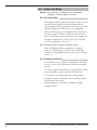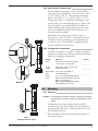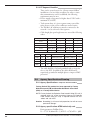
1
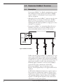
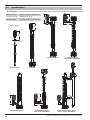
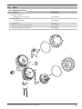
Enhanced Model 2xx FOUNDATION Fieldbus™ Digital Output Software v3.x FOUNDATION Fieldbus™ Operating Manual Magnetostrictive Level Transmitter A Magnetrol Company Read this Manual Before Installing This manual provides information on the Jupiter® magnetostrictive transmitter. It is important that all instructions are read carefully and followed in sequence. Detailed instructions are included in the Installation section of this manual. Conventions Used in this Manual Certain conventions are used in this manual to convey specific types of information. General technical material, support data, and safety information are presented in narrative form. The following styles are used for notes, cautions, and warnings. Notes Notes contain information that augments or clarifies an operating step. Notes do not normally contain actions. They follow the procedural steps to which they refer. Cautions Cautions alert the technician to special conditions that could injure personnel, damage equipment, or reduce a component’s mechanical integrity. Cautions are also used to alert the technician to unsafe practices or the need for special protective equipment or specific materials. In this manual, a caution box indicates a potentially hazardous situation which, if not avoided, may result in minor or moderate injury. Warnings Warnings identify potentially dangerous situations or serious hazards. In this manual, a warning indicates an imminently hazardous situation which, if not avoided, could result in serious injury or death. Safety Messages Follow all standard industry procedures for servicing electrical equipment when working with or around high voltage. Always shut off the power supply before touching any components. WARNING! Explosion hazard. Do not connect or disconnect equipment unless power has been switched off or the area is known to be non-hazardous. Low Voltage Directive For use in Installation Category II, Pollution Degree 2. If equipment is used in a manner not specified by the manufacturer, protection provided by the equipment may be impaired. Notice of Trademark, Copyright, and Limitations Orion & Orion logotype, Magnetrol & Magnetrol logotype, and Jupiter are registered trademarks of Magnetrol International. Copyright © 2011 Magnetrol International. All rights reserved. Performance specifications are effective with date of issue and are subject to change without notice. Magnetrol reserves the right to make changes to the product described in this manual at any time without notice. Magnetrol makes no warranty with respect to the accuracy of the information in this manual. Warranty All Magnetrol/Orion electronic level and flow controls are warranted free of defects in materials or workmanship for one full year from the date of original factory shipment. If returned within the warranty period; and, upon factory inspection of the control, the cause of the claim is determined to be covered under the warranty; then, Magnetrol/Orion will repair or replace the control at no cost to the purchaser (or owner) other than transportation. Magnetrol/Orion shall not be liable for misapplication, labor claims, direct or consequential damage or expense arising from the installation or use of equipment. There are no other warranties expressed or implied, except special written warranties covering some Magnetrol/Orion products. Quality Assurance The quality assurance system in place at Magnetrol guarantees the highest level of quality throughout the company. Magnetrol is committed to providing full customer satisfaction both in quality products and quality service. Magnetrol’s quality assurance system is registered to ISO 9001 affirming its commitment to known international quality standards providing the strongest assurance of product/service quality available. 57-649 Jupiter Magnetostrictive Transmitter - FOUNDATION fieldbus™ FOUNDATION Fieldbus™ Enhanced Jupiter® Model 2xx Magnetostrictive Level Transmitter Table of Contents 1.0 FOUNDATION fieldbus™ Overview ...................................4 1.1 Description ...............................................................4 1.2 Benefits .....................................................................5 1.3 Device Configuration................................................5 1.4 Intrinsic Safety ..........................................................6 2.0 Complete Installation.....................................................7 2.1 Unpacking ................................................................7 2.2 Electrostatic Discharge (ESD) Handling Procedure...7 2.3 Before You Begin.......................................................8 2.3.1 Site Preparation ..............................................8 2.3.2 Equipment and Tools .....................................8 2.3.3 Operational Considerations............................9 2.3.4 Configuration Information.............................9 2.4 Mounting..................................................................9 2.4.1 External..........................................................9 2.4.2 Internal, Direct Insertion..............................10 2.5 Wiring ....................................................................11 3.0 Function Blocks............................................................12 3.1 Overview.................................................................12 3.1.1 Universal Fieldbus Block Parameters ............12 3.2 Resource Block........................................................13 3.3 Transducer Block.....................................................16 3.3.1 Transducer Block Parameters........................16 3.3.2 Password Parameters.....................................16 3.3.3 Jupiter Configuration Parameters .................17 3.4 User Calibration Parameters....................................17 57-649 Jupiter Magnetostrictive Transmitter - FOUNDATION fieldbus™ 3.4.1 Factory Parameters .......................................17 3.4.2 Firmware Version .........................................18 3.5 Analog Input Block.................................................18 3.5.1 AI Block Parameters .....................................18 4.0 Diagnostic Parameters ..................................................20 4.1 Simulation Feature ..................................................21 5.0 Reference Information..................................................22 5.1 Troubleshooting ......................................................22 5.1.1 Troubleshooting ...........................................22 5.1.2 Status Messages ............................................23 5.1.3 FF Segment Checklist ..................................24 5.2 Agency .....................................................................24 5.2.1 Agency Specifications – Explosion Proof Installation .........................24 5.2.2 Agency Specifications – ATEX Intrinsically Safe ................................24 5.2.3 Agency Drawing...........................................25 5.3 Specifications ..........................................................27 5.3.1 Functional ....................................................27 5.3.2 Performance .................................................27 5.3.3 Physical ........................................................28 5.4 Parts ........................................................................29 5.4.1 Replacement Parts ........................................29 5.5 References ...............................................................30 Appendix ...............................................................30 Configuration Data Sheet .....................................31 1.0 FOUNDATION fieldbus™ Overview 1.1 Description FOUNDATION fieldbus™ is a digital communications system that serially interconnects devices in the field. A Fieldbus system is similar to a Distributed Control System (DCS) with two exceptions: • Although a FOUNDATION fieldbus™ system can use the same physical wiring as an existing 4–20 mA device, Fieldbus devices are not connected point to point, but rather are multidropped and wired in parallel on a single pair of wires (referred to as a segment). • FOUNDATION fieldbus™ is a system that allows the user to distribute control across a network. Fieldbus devices are smart and actually maintain control over the system. 6234 feet (1900 meters) maximum PC Power Conditioner Terminator Terminator Power Supply Control Room Typical Fieldbus Installation Unlike 4–20 mA analog installations in which the two wires carry a single variable (the varying 4–20 mA current), a digital communications scheme such as FOUNDATION fieldbus™ considers the two wires as a network. The network can carry many process variables as well as other information. The Enhanced Jupiter transmitter is a FOUNDATION fieldbus™ registered device that communicates with the H1 FOUNDATION fieldbus™ protocol operating at 31.25 kbits/sec. The H1 physical layer is an approved IEC 61158 standard. An IEC61158 shielded twisted pair wire segment can be as long as 6234 feet (1900 meters) without a repeater. Up to 4 repeaters per segment can be used to extend the distance. The maximum number of devices allowed on a Fieldbus segment is 32 although this depends on the current draw of the devices on any given segment. 4 57-649 Jupiter Magnetostrictive Transmitter - FOUNDATION fieldbus™ Details regarding cable specifications, grounding, termination, and other network information can be found in IEC 61158 or the wiring installation application guide AG-140 at www.fieldbus.org. 1.2 Benefits The benefits of FOUNDATION fieldbus™ can be found throughout all phases of an installation: 1. Design/Installation: Connecting multiple devices to a single pair of wires means less wire and fewer I/O equipment. Initial Engineering costs are also reduced because the Fieldbus Foundation requires interoperability, defined as “the ability to operate multiple devices in the same system, regardless of manufacturer, without a loss of functionality.” All FOUNDATION fieldbus™ devices must be tested for interoperability by the Fieldbus Foundation. Orion Instruments Jupiter device registration can be found at www.fieldbus.org. Choose Magnetrol as the device manufacturer when searching for the registration. 2. Operation: With control now taking place within the devices in the field, better loop performance and control are the result. A FOUNDATION fieldbus™ system allows for multiple variables to be brought back from each device to the control room for additional trending and reporting. 3. Maintenance: The self-diagnostics residing in the smart field devices minimizes the need to send maintenance personnel to the field. 1.3 Device Configuration Device Descriptions The function of a FOUNDATION fieldbus™ device is determined by the arrangement of a system of blocks defined by the Fieldbus Foundation. The types of blocks used in a typical User Application are described as follows: Resource Block describes the characteristics of the FOUNDATION fieldbus™ device such as the device name, manufacturer, and serial number. Function Blocks are built into the FOUNDATION fieldbus™ devices as needed to provide the desired control system behavior. The input and output parameters of function blocks can be linked over the Fieldbus. There can be numerous function blocks in a single User Application. Transducer Blocks contain information such as calibration parameters and sensor type. They are used to connect the sensor to the input function blocks. 57-649 Jupiter Magnetostrictive Transmitter - FOUNDATION fieldbus™ 5 An important requirement of Fieldbus devices is the interoperability concept mentioned earlier. Device Description (DD) technology is used to achieve this interoperability. The DD provides extended descriptions for each object and provides pertinent information needed by the host system. DDs are similar to the drivers that your personal computer (PC) uses to operate peripheral devices connected to it. Any Fieldbus host system can operate with a device if it has the proper DD and Common File Format (CFF) for that device. The most recent DD and CFF files can be found on the FOUNDATION fieldbus™ web site at fieldbus.org. 1.4 Intrinsic Safety The H1 physical layer supports Intrinsic Safety (IS) applications with bus-powered devices. To accomplish this, an IS barrier or galvanic isolator is placed between the power supply in the safe area and the device in the hazardous area. H1 also supports the Fieldbus Intrinsically Safe Concept (FISCO) model which allows more field devices in a network. The FISCO model considers the capacitance and inductance of the wiring to be distributed along its entire length. Therefore, the stored energy during a fault will be less and more devices are permitted on a pair of wires. Instead of the conservative entity model, which only allows about 90 mA of current, the FISCO model allows a maximum of 110 mA for Class II C installations and 240 mA for Class II B installations. FISCO certifying agencies have limited the maximum segment length to 1000 meters because the FISCO model does not rely on standardized ignition curves. The Enhanced Jupiter Magnetostrictive transmitter is available with entity IS, FISCO IS, FNICO non-incendive, or explosion proof approvals. 6 57-649 Jupiter Magnetostrictive Transmitter - FOUNDATION fieldbus™ 2.0 Installation Caution: If equipment is used in a manner not specified by manufacturer, protection provided by equipment may be impaired This section provides detailed procedures for properly installing, wiring, configuring and, if needed, troubleshooting the Jupiter magnetostrictive level transmitter. In most cases the unit will be shipped from the factory attached to the Orion Instruments magnetic level indicator. In some cases, such as retrofit applications of a reed chain transmitter with a Jupiter instrument, the installation and set up will need to be performed in the field. 2.1 Unpacking Unpack the instrument carefully. Inspect all units for damage. Report any concealed damage to carrier within 24 hours. Check the contents against the packing slip and purchase order. Check and record the serial number for future reference when ordering parts. Caution: Do not discard the shipping container until all parts are accounted for and inspected. 2.2 Electrostatic Discharge (ESD) Handling Procedure Magnetrol/Orion’s electronic instruments are manufactured to the highest quality standards. These instruments use electronic components that may be damaged by static electricity present in most work environments. • • • • 57-649 Jupiter Magnetostrictive Transmitter - FOUNDATION fieldbus™ The following steps are recommended to reduce the risk of component failure due to electrostatic discharge. Ship and store circuit boards in anti-static bags. If an antistatic bag is not available, wrap the board in aluminum foil. Do not place boards on foam packing materials. Use a grounding wrist strap when installing and removing circuit boards. A grounded workstation is recommended. Handle circuit boards only by the edges. Do not touch components or connector pins. Make sure that all electrical connections are completely made and none are partial or floating. Ground all equipment to a good, earth ground. 7 2.3 Before You Begin Caution: This instrument is intended for use in Installation Category II, Pollution Degree 2 locations. 2.3.1 Site Preparation Each Jupiter magnetostrictive transmitter is built to match the specifications required within the defined model option number. Wiring terminations will need to be made and the configuration will need to be accomplished. Ensure that the power to be supplied to the instrument is the same voltage (24 VDC) as ordered with the instrument, and that the wiring between the power supply and the Jupiter transmitter is correct for the type of installation. See Specifications, Section 5.3. NOTE: Applying incorrect voltage will damage the unit. When installing the Jupiter transmitter in a general purpose or hazardous area, all local, state, and federal regulations and guidelines must be observed. See Wiring, Section 2.5. 2.3.2 Equipment and Tools For installation of a new Jupiter with magnetic level indicator set, refer to Orion Instruments instruction manual 46-638. To attach a Jupiter transmitter to an existing MLI or direct insertion model, you may need the following tools: • 5⁄16" Nut-Driver (for tightening the mounting clamps). • Screwdriver and assorted hand tools for making conduit and electrical connections. • Digital multimeter or DVM to troubleshoot supply voltage problems. 8 57-649 Jupiter Magnetostrictive Transmitter - FOUNDATION fieldbus™ 2.3.3 Operational Considerations Exterior ambient temperature of the service should not exceed the design specifications of the electronics (-40° to +175° F (-40° to +80° C)). The operating temperature limits of the LCD are -5° to +160° F (-20° to +70° C). Temperatures below -5° F will cause the display to temporarily white out, and temperatures above +160° F will cause the display to go temporarily black. It will recover without damage when the operating temperature range returns. A sunshade should be used if electronics are mounted in direct sunlight. Maximum process temperature for direct insertion transmitters is +500° F (+260° C). Externally mounted transmitters can be used with process temperatures up to +800° F (+427° C) if the MLI is equipped with an insulation blanket from the factory. 2.3.4 Configuration Information Some key information is needed to configure the Jupiter transmitter. Complete the following operating parameters table before beginning configuration. Display Units Probe Length Question What units of measurement will be used? (inches or centimeters) _____________ What probe length is listed on the model information? _____________ Measurement Choose from Level Only or Type Level and Interface Sensor Mount 2.4 Choose from MLI Top, MLI Bottom, Direct Insertion Near (NPT, BSP, and 600# or less flanges) or Direct Insertion Extended (Flanged probes 900# class and over) Answer _____________ _____________ Mounting 2.4.1 External Caution: Do not rotate the Jupiter electronics enclosure. Rotating the electronics enclosure could cause damage to sensor cables. If ordered from the factory with the MLI, it will be attached to the gauge and configured for the measuring range specified at the time of order placement. If not, use the following directions: 1. Place the Jupiter transmitter and mounting clamps in a convenient location. Figure 1 Mounting External Jupiter 57-649 Jupiter Magnetostrictive Transmitter - FOUNDATION fieldbus™ 9 Upper Clamp Figure 2 2. Position the Jupiter transmitter on the side of the MLI where it will be attached. Mark the location and the exact area where the clamps will be attached to hold the Jupiter in place. 3. Attach the lower clamp and tighten so that it remains in place, but loose enough so that there is still room to place the guide tab from the Jupiter between the inside of the clamp and the outer diameter of the MLI chamber. See Figure 1. 4. The upper clamp will need to be open to a large enough diameter to be able to mount to the MLI as well as the probe. The upper clamp should be positioned just above the 3⁄4" NPT threads. See Figure 2. 5. Mount the Jupiter guide pin in the lower clamp and tighten. If necessary, use strapping tape to temporarily hold in place on the MLI. See Figure 1. 6. Position the upper clamp to attach the unit to the MLI and tighten. See Figure 1. 7. Discard any tape temporarily holding the Jupiter to the MLI. 2.4.2 Internal, Direct Insertion Up © Bottom view Use caution when handling probes to ensure probe is not bent during installation. A bend in the probe may prevent float from traveling freely up and down the probe. 1. Verify float will pass through vessel opening, if not, it will be necessary to attach the float after the probe is installed. 2. Carefully insert probe into vessel and thread or bolt to the mating connection as appropriate. 3. The float is held on the probe by a C-clip inserted into a groove machined into the tip of the probe. The float is attached or removed by removing and reinserting the C-clip. See Figure 3. To ensure proper float orientation, the float is marked “Up ”. Figure 3 Float Attachment Detail 10 57-649 Jupiter Magnetostrictive Transmitter - FOUNDATION fieldbus™ 2.5 Wiring Caution: The Jupiter magnetostrictive transmitter operates at voltages of 9-32 VDC (nominal voltage is 24 VDC). Higher voltages will damage the transmitter. Wiring between the power supply and the Jupiter transmitter should be made using 18–22 AWG shielded twisted pair instrument cable. The transmitter enclosure consists of two compartments. The upper compartment is used to terminate the field wires (wiring termination compartment), and the lower compartment is the electronics compartment. Red (+) Black (-) )+( )-( The Jupiter is offered for use in Class I, Div 1 areas (flammable gasses may be present). Follow the instructions below to complete wiring of the instrument. WARNING! Explosion hazard. Do not disconnect equipment unless power has been switched off or the area is known to be non-hazardous. Figure 4 An explosion proof (XP) installation potentially has flammable vapors or media present. Covers on instruments in these areas must remain on and tight while power is applied to the instrument. Wiring Diagram Equipment installed in an area classified as Class I, Div 2, reflects that flammable or explosive vapors may be present. 1. 2. 3. 4. 5. 6. 7. To install intrinsically safe wiring, make sure the IS barrier is properly installed in the safe area (refer to local plant or facility procedures). Complete the wiring from the barrier to the Jupiter transmitter. See Agency Specifications– Intrinsically Safe Installations, Section 5.2.2. Make sure power is off in any junction box which will be exposed to the atmosphere, unless the area has already been sniffed and approved free of flammable vapors. The top cover (field wiring compartment) of the Jupiter transmitter may be removed. Place the cover in a location where dirt will not get on the threads. Attach the black wire (-) to the negative terminal on the termination strip. Attach the red wire (+) to the positive wire on the termination strip. Ground shield at power supply. Tighten and check connections, then replace cover. An explosion proof seal is not required unless specifically noted by the local code. Note: All local, state and federal regulations and codes must be adhered to during and after installation. 57-649 Jupiter Magnetostrictive Transmitter - FOUNDATION fieldbus™ 11 8. Power may be applied to the instrument when the installation is complete and has been checked by the instrument engineer or safety officer. 3.0 Function Blocks 3.1 Overview The Enhanced Jupiter Model 2xx is a level transmitter with four FOUNDATION fieldbus™ Function Blocks (one Resource Block, one Transducer Block, and two Analog Input blocks. The idea of Function Blocks, which a user can customize for a particular application, is a key concept of Fieldbus topology. Function Blocks consist of an algorithm, inputs and outputs, and a user-defined name. The TRANSDUCER block output is available to the network through the ANALOG INPUT blocks. • The ANALOG INPUT blocks (AI) take the TRANSDUCER block level values and makes them available as an analog value to other function blocks. The AI blocks have scaling conversion, filtering, and alarm functions. 3.1.1 Universal Fieldbus Block Parameters The following are general descriptions of the parameters common to all blocks. Additional information for a given parameter is described later in that specific block section. ST_REV (static data revision): a read only parameter that gives the revision level of the static data associated with the block. This parameter will be incremented each time a static parameter attribute value is written and is a vehicle for tracking changes in static parameter attributes. TAG_DESC (tag descriptor): a user assigned parameter that describes the intended application of any given block. STRATEGY: a user assigned parameter that identifies groupings of blocks associated with a given network connection or control scheme. ALERT_KEY: a user assigned parameter which may be used in sorting alarms or events generated by a block. MODE_BLK: a structured parameter composed of the actual mode, the target mode, the permitted mode(s), and the normal mode of operation of a block. • The actual mode is set by the block during its execution to reflect the mode used during execution. • The target mode may be set and monitored through the mode parameter. 12 57-649 Jupiter Magnetostrictive Transmitter - FOUNDATION fieldbus™ • The permitted modes are listed for each block. • The block must be in an automatic mode for normal operation. NOTE: The MODE_BLK target parameter must be OOS (out of service) to change configuration and calibration parameters in that function block (when in OOS, the normal algorithm is no longer executed and any outstanding alarms are cleared). All blocks must be in an operating mode for the device to operate. This requires the Resource Block to be in “AUTO” and the Transducer Block to be in “AUTO” before the Function Blocks can be placed in a mode other than OOS (out of service). BLOCK_ERR: a parameter that reflects the error status of hardware or software components associated with, and directly affecting, the correct operation of a block. NOTE: A BLOCK_ERR of “Simulation Active” in the Resource Block does not mean simulation is active—it merely indicates that the simulation (hardware) enabling jumper is present. 3.2 Resource Block The RESOURCE block contains data specific to the Enhanced Jupiter transmitter, along with some information about the firmware. NOTE: The Resource Block has no control function. MODE_BLK: Must be in AUTO in order for the remaining blocks in the transmitter to operate. NOTE: A Resource Block in “out of service” will stop all function block execution in the transmitter. RS_STATE (Resource State): identifies the state of the RESOURCE block state machine. Under normal operating conditions, it should be “On-Line.” DD_RESOURCE: a string identifying the tag of the resource that contains the Device Description for this device. MANUFAC_ID: contains Magnetrol International’s FOUNDATION fieldbus™ manufacturer’s ID number, which is 0x000156. DEV_TYPE: the Device Type of the Enhanced Jupiter 2xx transmitter (0x0002). It is used by interface devices to locate the Device Description (DD) file for this product. DEV_REV: contains the firmware revision of the Enhanced Jupiter transmitter. It is used by interface devices to correctly select the associated DD. 57-649 Jupiter Magnetostrictive Transmitter - FOUNDATION fieldbus™ 13 DD_REV: contains the revision of the DD associated with the version of firmware in the Enhanced Jupiter transmitter. It is used by interface devices to correctly select the associated DD. RESTART: Default and Processor selections are available. Default will reset the Jupiter to the established block configuration. NOTE: As RESTART DEFAULT will set all configuration parameters to their default values. Devices need to be reconfigured following activation of this function FEATURES: a list of the features available in the transmitter. The Jupiter Model 2xx features include Reports, and Soft Write Locking. FEATURES_SEL: allows the user to turn Features on or off. CYCLE_TYPE: identifies the block execution methods that are available. CYCLE_SEL: allows the user to select the block execution method. MIN_CYCLE_T: the time duration of the shortest cycle interval. It puts a lower limit on the scheduling of the resource. NV_CYCLE_T: the minimum time interval between copies of non-volatile (NV) parameters to NV memory. NV memory is only updated if there has been a significant change in the dynamic value and the last value saved will be available for the restart procedure. A value of “0” means it will never be automatically copied. Entries made by human interface devices to NV parameters are copied to non-volatile memory at the time of entry. NOTE: After completing a large copy, allow several seconds before removing power from the Jupiter Model 2xx transmitter to ensure that all data has been saved. FREE_SPACE: shows the amount of available memory for further configuration. The value is zero percent in a preconfigured device. FREE_TIME: the amount of the block processing time that is free to process additional blocks. SHED_RCAS: the time duration at which to give up computer writes to function block RCas locations. Shed from RCas will never happen when SHED_RCAS = 0. SHED_ROUT: the time duration at which to give up computer writes to function block ROut locations. Shed from ROut will never happen when SHED_ROUT = 0. 14 57-649 Jupiter Magnetostrictive Transmitter - FOUNDATION fieldbus™ FAULT_STATE, SET_FSTATE, CLR_FSTATE: these only apply to output function blocks. (The Model 2xx has no output function blocks). MAX_NOTIFY: the maximum number of alert reports that the transmitter can send without getting a confirmation. The user can set the number low, to control alert flooding, by adjusting the LIM_NOTIFY parameter value. LIM_NOTIFY: the maximum numbers of unconfirmed alert notify messages allowed. No alerts are reported if set to zero. CONFIRM_TIME: the time that the transmitter will wait for confirmation of receipt of a report before trying again. Retry will not occur if CONFIRM_TIME = 0. WRITE_LOCK: When set to LOCKED, will prevent any external change to the static or non-volatile data base in the Function Block Application of the transmitter. Block connections and calculation results will proceed normally, but the configuration will be locked. UPDATE_EVT (Update Event): is an alert generated by a write to the static data in the block. BLOCK_ALM (Block Alarm): is used for configuration, hardware, connection, or system problems in the block. The cause of any specific alert is entered in the subcode field. The first alert to become active will set the Active status in the Status attribute. As soon as the Unreported status is cleared by the alert reporting task, another block alert may be reported without clearing the Active status, if the subcode has changed. ALARM_SUM (Alarm Summary): contains the current alert status, the unacknowledged states, the unreported states, and the disabled states of the alarms associated with the block. ACK_OPTION (Acknowledge Option): selects whether alarms associated with the block will be automatically acknowledged. WRITE_PRI (Write Priority): the priority of the alarm generated by clearing the write lock. WRITE ALM (Write Alarm): the alert generated if the write lock parameter is cleared. ITK_VER (ITK Version): contains the version of the Interoperability Test Kit (ITK) used by the Fieldbus Foundation during their interoperability testing. 57-649 Jupiter Magnetostrictive Transmitter - FOUNDATION fieldbus™ 15 3.3 Transducer Block The TRANSDUCER block is a custom block containing parameters that support the enhanced level transmitter. It contains the Jupiter probe configuration, diagnostics, and calibration data, and outputs level with status information. The TRANSDUCER block parameters are grouped in a useful configuration. There are both read-only parameters and read-write parameters within the TRANSDUCER block. • The read-only parameters report the block status and operation modes. • The read-write parameters affect the function block basic operation, level transmitter operation, and calibration. The Transducer Block Mode will automatically be changed to “Out of Service” when the local interface (keypad) is used to change a parameter online. 3.3.1 Transducer Block Parameters The first six parameters in the TRANSDUCER block are the universal parameters discussed in section 3.1.1. The universal parameters are followed by these additional required parameters: UPDATE_EVT (Update Event): an alert generated by a write to the static data in the TRANSDUCER block. Another important parameter found later in the TRANSDUCER block list is DEVICE_STATUS, which displays the status of the device. If more than one message exists, then the messages are displayed in priority order. Refer to Section 5.1.2, Status Messages. If DEVICE_STATUS indicates a problem, refer to Section 5.1.1, Troubleshooting (those parameters which are shaded are password-protected). For a complete list of Transducer Block Parameters, refer to table in the Appendix. 3.3.2 Password Parameters To change a parameter at the local user interface, a value matching the user password must be entered (Default=1). If the user password is entered, the instrument is in the user mode. After 5 minutes with no keypad activity, the entered password expires. Factory password is for use by trained factory personnel only. From the network, the instrument always behaves as if it is in the user mode by default. In other words, it is not necessary to enter the user password in order to write parameters from the network. 16 57-649 Jupiter Magnetostrictive Transmitter - FOUNDATION fieldbus™ 3.3.3 Jupiter Configuration Parameters This set of parameters within the Transducer Block is important and required to configure every Jupiter transmitter. Sensor Mount MEASUREMENT_TYPE Select from LEVEL_ONLY or LEVEL&INTERFACE. 100% Set Point PROBE_LENGTH Enter the exact length of probe. The probe length is shown as the last 3 digits of the probe model number printed on the nameplate attached to the transmitter. Probe Length LEVEL_OFFSET Enter the distance from the probe tip to the desired 0% reference in PROBE_LEVEL_UNITs. The acceptable range is from -99 to 150 inches. 0% Set Point SENSOR_MOUNT Select from MLI_TOP, MLI_BOTTOM, DIRECT_NEAR or DIRECT_EXTENDED. Level Offset 3.4 User Calibration Parameters One of the main advantages of the Enhanced Jupiter Model 2XX is that every Enhanced Jupiter Model 2XX transmitter is shipped from the factory precisely calibrated. On the other hand, part of the advantage of FOUNDATION fieldbus is to provide the ability to monitor changes and adjustments to a transmitter. The Fieldbus concept allows a user to make calibration adjustments if deemed necessary. NOTE: The original factory calibration settings are restored when a new probe length value is assigned. It is highly recommended that factory calibration be used for optimum performance. 3.4.1 Factory Parameters The factory-adjustable calibrated parameters are: CONVERSION_FACTOR, SCALE_OFFSET, FLOAT_THRESHOLD and FLOAT_POLARITY. The following parameters are used for either troubleshooting or are parameters adjusted at the factory. They should never be changed in the field. CONVERSION_FACTOR: compensates for changes in signal propagation. SCALE_OFFSET: the intercept of the calibration line. FLOAT_THRESHOLD: controls the threshold voltage level. FLOAT_POLARITY: defines level as positive or negative pulse. SENSITIVITY: signal detector adjustment. DRIVE_AMPLITUDE: sets amplitude of the out going pulse. 57-649 Jupiter Magnetostrictive Transmitter - FOUNDATION fieldbus™ 17 3.4.2 Firmware Version The last two parameters in the TRANSDUCER block show the firmware version of the transmitter. FIRMWARE_VERSION: displays the version of the firmware. COPROCESSOR_VERSION: displays the version of the coprocessor. 3.5 Analog Input Block The ANALOG INPUT (AI) block takes the transducer blocks input data, selected by channel number, and makes it available to other function blocks at its output: Channels 1. Level 2. Interface Level 3.5.1 AI Block Parameters PV: Either the primary analog value for use in executing the function, or a process value associated with it. OUT: The primary analog value calculated as a result of executing the function block. Probe Mount SIMULATE: Allows the transducer analog input or output to the block to be manually supplied when simulate is enabled. When simulate is disabled, the simulate value and status track the actual value and status 100% Set Point Probe Model Probe Length 0% Set Point Level Offset Scaling XD_SCALE: The high and low scale values, engineering units code, and number of digits to the right of the decimal point used with the value obtained from the transducer for a specified channel. OUT_SCALE: The high and low scale values, engineering units code, and number of digits to the right of the decimal point to be used in displaying the OUT parameter. GRANT_DENY: Options for controlling access of host computers and local control panels to operating, tuning, and alarm parameters of the block. IO_OPTS: Option which the user may select to alter input and output block processing. STATUS_OPTS: Options which the user may select in the block processing of status. 18 57-649 Jupiter Magnetostrictive Transmitter - FOUNDATION fieldbus™ CHANNEL: The number of the logical hardware channel that is connected to this I/O block. This information defines the transducer to be used going to or from the physical world. L_TYPE: Determines if the values passed by the transducer block to the AI block may be used directly (Direct) or if the value is in different units and must be converted linearly (Indirect), or with square root (Ind Sqr Root), using the input range defined for the transducer and the associated output range. LOW_CUT: Limit used in square root processing. PV_FTIME: Time constant of a single exponential filter for the PV, in seconds. FIELD_VAL: Raw value of the field device in % of PV range, with a status reflecting the Transducer condition, before signal characterization (L_TYPE) or filtering (PV_FTIME). UPDATE_EVT: This alert is generated by any change to the static data. BLOCK_ALM: The block alarm is used for all configuration, hardware, connection failure or system problems in the block. ALARM_SUM: The current alert status, unacknowledged states, unreported states, and disabled states of the alarms associated with the function block. ACK_OPTION: Selection of whether alarms associated with the function block will be automatically acknowledged. ALARM_HYS: Amount the PV must return within the alarm limits before the alarm condition clears. Alarm hysteresis expressed as a percent of the span of the PV. HI_HI_PRI: Priority of the high high alarm. HI_HI_LIM: The setting for high high alarm in engineering units. HI_PRI: Priority of the high alarm. HI_LIM: The setting for high alarm in engineering units LO_PRI: Priority of the low alarm. LO_LIM: The setting for low alarm in engineering units. LO_LO_PRI: Priority of the low low alarm. LO_LO_LIM: The setting for low low alarm in engineering units. HI_HI_ALM: The status for high high alarm and its associated time stamp. 57-649 Jupiter Magnetostrictive Transmitter - FOUNDATION fieldbus™ 19 HI_ALM: The status for high alarm and its associated time stamp. LO_ALM: The status for low alarm and its associated time stamp. LO_LO_ALM: The status for low low alarm and its associated time stamp. The TRANSDUCER and AI block’s MODE_BLK parameter must be set to AUTO to pass the PV Value through the AI to the network. Transducer scaling, called XD_SCALE, is applied to the PV from the CHANNEL to produce the FIELD_VAL in percent. Valid XD_SCALE in engineering units is limited to the three allowable codes of centimeters (cm), inches (in), and percent (%). 1. 2. 3. 4. The AI can have a BLOCK_ERR when: Channel is not set correctly. XD_SCALE does not have suitable engineering units or has range incompatibility. SIMULATE parameter is active AI block MODE is O/S (out of service). NOTE: This can be caused by the Resource Block being OOS or the AI Block not scheduled for execution. 5. L-TYPE not set or set to Direct with improper OUT_SCALE. The AI uses the STATUS_OPTS setting and the TRANSDUCER PV LIMIT value to modify the AI PV and OUT QUALITY. Damping Filter is a feature of the AI block. PV_FTIME parameter is time constant of a single exponential filter for the PV, in seconds. This parameter can be used to dampen out fluctuation in level due to excessive turbulence. The AI block has multiple ALARM functions that monitor the OUT parameter for out of bound conditions. 4.0 Diagnostic Parameters The Jupiter Model 2xx measurement engine runs through a series of self-tests and will detect and report faulty operation. The TRANSDUCER BLOCK displays these faults in the DEVICE_STATUS parameter and the PV Quality and Substatus. Refer to Section 5.1.2 for more information on specific faults and warnings. BLOCK_ERROR is not used except for indicating Out of Service (OOS). 20 57-649 Jupiter Magnetostrictive Transmitter - FOUNDATION fieldbus™ When the Model 2xx transmitter is initially powered on, the measurement engine does not have enough valid measurement cycles to make a decision about the output level. For the first sixteen measurement cycles after power is applied, the QUALITY is “Uncertain,” the SUB_STATUS is “Initial value,” and the LIMIT attribute is “Constant.” When the Model 2xx is operating correctly, the QUALITY is shown as “GOOD,” and the SUB_STATUS is “NonSpecific.” While changing the transmitter operational parameters using the local display or through the system configuration tool (with the MODE_BLK in OOS), the output might be inaccurate because of the changing parameters. When the device is in a mode where operational parameters can be changed, the TRANSDUCER BLOCK will still output level but the QUALITY will be shown as “Bad” and the SUB_STATUS is “Out of Service.” When the Enhanced Jupiter measurement cycle fails to find a valid output level, the transmitter maintains the last good value as the output and flags the failure. The LIMIT attribute is the same as the last good measurement. Excessive disrupted cycles causes the transmitter to go into a defined operational mode based on the cause of the disrupted cycles. 4.1 Simulation Feature The Jupiter Model 2xx with FOUNDATION fieldbus™ supports the Simulate feature in the Analog Input block. The Simulate feature is typically used to exercise the operation of an AI block by simulating a TRANSDUCER block input. This feature can not be activated without the placement of a hardware jumper. This jumper is installed as standard on the Jupiter Model 2xx, and is placed in an inconvenient location to avoid inadvertent disabling of this feature. NOTE: A BLOCK_ERR of “Simulation Active” in the Resource Block does not mean simulation is active—it merely indicates that the simulation (hardware) enabling jumper is present. Contact the factory for instructions on how to remove this jumper and permanently disable the Simulate feature. 57-649 Jupiter Magnetostrictive Transmitter - FOUNDATION fieldbus™ 21 5.0 Reference Information 5.1 Troubleshooting The Jupiter transmitter is designed and manufactured for years of trouble free operation over a wide range of conditions. Common transmitter problems are discussed in terms of their symptoms and recommended corrective actions. 5.1.1 Troubleshooting Problem Solution Transmitter does not track level (External Mount) Remove transmitter from piping column and test with re-alignment magnet. Run magnet from bottom to top of probe. Check zero and span calibration. If no change in output, consult the factory. (Direct Insertion) Float stuck, Probe bent (Chamber) Float inside the level gauge is moving slow Ensure that the magnetic level indicator is plumb. or not at all. The process fluid being measured may be too viscous and heat tracing may be required to make the material more fluid. The specific gravity of the process fluid and float weight may need to be reverified. The liquid being measured may contain magnetic particles collecting on the magnetic section of the float causing drag. If this happens magnetic trap assemblies can be purchased from the factory. Visual inspection of the float may be required to see if the float has collapsed. LEVEL value is inaccurate. Basic configuration data is questionable. Reconfigure probe length and offset. Ensure the level is accurate. Reconfigure loop values. LEVEL value fluctuates. Turbulence, increase damping factor until readings stabilize. 22 57-649 Jupiter Magnetostrictive Transmitter - FOUNDATION fieldbus™ 5.1.2 Status Messages Display Message Action Comment OK None Normal operating mode Initial None Shown at power-up during self check Default Cal Factory set default calibration parameters are in use, level reading may be inaccurate Consult Factory Lo Temp Present temperature in electronics compartment is below -40° C Transmitter may need to be moved to ensure temperature is within specification Hi Temp Present temperature in electronics compartment is above +80° C Transmitter may need to be moved to ensure temperature is within specification Float 2 Fail No level signal detected from float 2 Make sure 2 floats are being used, are not damaged, and within measuring range Float 1 Fail No level signal detected from float 1 Make sure float is not damaged and within measurement range No Signal No signal detected from any float Make sure float is not damaged and within measurement range Snsr Brd Fail No signal from probe, bad board or connection problem Check electrical connections to probe DfltParm Internal non-volatile, parameters have been defaulted Consult Factory 57-649 Jupiter Magnetostrictive Transmitter - FOUNDATION fieldbus™ 23 5.1.3 FF Segment Checklist • • • • There can be several reasons for a FOUNDATION fieldbus™ installation to be in a faulty condition. In order to assure that communication can be established, the following requirements must be met. Device supply voltage must be higher than 9 VDC with a maximum of 32 VDC. Total current draw of a given segment cannot exceed the rating shown on the power conditioner and/or barrier. Two 100 Ω, 1 µF terminators must be connected to the network—one at each end of the segment. Cable length plus spur length must not exceed the following values: Number of Spurs 1 Device 2 Devices 3 Devices 4 Devices 25–32 — — — — 19–24 100 ft. (30 m) — — — 15–18 200 ft. (60 m) 100 ft. (30 m) — — 13–14 300 ft. (90 m) 200 ft. (60 m) 100 ft. (30 m) — 1–12 400 ft. (120 m) 300 ft. (90 m) 200 ft. (60 m) 100 ft. (30 m) Pair Shield Twisted Size Length Type Single Yes Yes AWG 18 (0.8 mm2) 6,200 ft. (1,900 m) A Multi Yes Yes AWG 22 (0.32 mm2) 3,900 ft. (1,200 m) B Multi No Yes AWG 26 (0.13 mm2) 1,300 ft. (400 m) C Multi Yes No AWG 16 (1.25 mm2) 650 ft. (200 m) D • The cable shield is to be hard grounded only at one point close to the DCS. In addition, the cable shield can be capacitively grounded in multiple places to improve EMC protection. 5.2 Agency Specifications/Drawing 5.2.1 Agency Specifications – Explosion Proof Installation Factory Sealed: This product has been approved by Factory Mutual Research (FM) and Canadian Standards Association (CSA) as a Factory Sealed device. NOTE: Factory Sealed: No Explosion Proof conduit fitting (EY seal) is required within 18" of the transmitter. However, an Explosion Proof conduit fitting (EY seal) is required between the hazardous and safe areas. Caution: Grounding (+) will cause faulty operation, but will not cause permanent damage. 5.2.2 Agency specifications ATEX Intrinsically safe Entity parameters Fieldbus Fisco: Ui = 17.5V Ii=380mA Pi = 5.32W Ci = 0.705 nF Li = 3µH 24 57-649 Jupiter Magnetostrictive Transmitter - FOUNDATION fieldbus™ 5.2.3 Agency Drawing 57-649 Jupiter Magnetostrictive Transmitter - FOUNDATION fieldbus™ 25 5.2.3 Agency Drawing 26 57-649 Jupiter Magnetostrictive Transmitter - FOUNDATION fieldbus™ 5.3 Specifications 5.3.1 Functional System Design Measurement Principle Magnetostrictive time-of-flight Input Measured Variable A return signal is generated from the precise location where the magnetic field of the MLI float intersects the magnetostrictive wire Zero and Span 6 inches to 400 inches (15 to 999 cm) User Interface Keypad 3-button menu-driven data entry and system security Indication 2-line × 8-character display Digital Communication FOUNDATION fieldbus™, H1 (31.25 kbits/sec) Interoperability test kit (ITK Revision) ITK 4.61 LAS capable Yes, Device type: Linkmaster Minimum Operating Voltage 9 VDC Quiescent Current Draw 15 mA DEV Revision 0X01 Function Blocks 1xRB, 2xAI(s) Damping Adjustable 0-25 seconds Power (Measured at instrument terminals) Fieldbus General Purpose/Explosion Proof 9 to 32 VDC (17 mA maximum current draw) FISCO/FNICO 9–17.5 VDC (17 mA maximum current draw) Housing Material Aluminum A356T6 (<0.20% copper), optional 316 stainless steel Cable Entry 3 ⁄4" NPT and M20 5.3.2 Performance Accuracy ±0.015" Repeatability ±0.005% of full span or 0.005" (0.127 mm) (whichever is greater) Linearity 0.020% of full span or 0.031" (0.794 mm) (whichever is greater) Maximum level rate of change 6 inches per second Response time 0.1 second Warm-up <5 second Upper dead zone None Lower dead zone <2" (5 cm), SIL 2: <5" (13 cm) Ambient temperature range Process temperature Transmitter: -40° to +175° F (-40° to +80° C) LCD: -10° to +160° F (-20° to +70° C) External Mount: -40° to +248° F (-40° to +120° C) -320° to +850° F (-195° to +455° C) (with factory insulated MLI) Direct Insertion: High temperature probe: Humidity -40° to +200° F (-40° to +95° C) -40° to +500° F (-40° to +260° C) 0 to 99% non-condensing Electromagnetic compliance EN 61326 Maximum Pressure (Direct Insertion) 1700 psig @ +100° F 57-649 Jupiter Magnetostrictive Transmitter - FOUNDATION fieldbus™ 27 5.3 Specifications 5.3.3 Physical Enclosure finish: Baked on polymer powder coat Enclosure rating: NEMA 4X7/9, IP 66 Sensor length: 6 to 400 inches (15 to 999 cm) 11.5 (292) 11 (279) 12.5 (318) 8 (203) Inches (mm) 8.00 (203) 11.5 (292) Flanged or NPT Connection MAD E IN USA MAD E IN USA Top Mount Offset Top Mount Offset High Temperature Bend MAD E IN USA Direct Insertion 11.5 (292) 11 (279) 12.5 (318) 8 (203) MAD E IN USA Bottom Mount Offset 28 Top Mount MAD E IN USA MAD E IN USA Bottom Mount Offset High Temperature Bend Gemini – Bottom Mount Offset and Secondary Transmitter 57-649 Jupiter Magnetostrictive Transmitter - FOUNDATION fieldbus™ 5.4 Parts 5.4.1 Replacement Parts Item Description Part Number Electronic module Display & FOUNDATION fieldbus™ 031-2840-001 Terminal board FOUNDATION fieldbus™ 030-9151-004 O-ring (Viton ) 012-2201-237 Aluminum housing cover without glass 004-9193-002 Aluminum housing cover with glass 036-4410-003 ® ➂ ➃ ➁ ➄ ➂ ➀ 57-649 Jupiter Magnetostrictive Transmitter - FOUNDATION fieldbus™ 29 5.5 References 1. FOUNDATION fieldbus™, A Pocket Guide Ian Verhappen, Augusto Pereira 2. FOUNDATION fieldbus™—System Engineering Guidelines, AG–181 Appendix – Transducer Block Parameters ITEM 0 1 2 3 4 5 6 7 8 9 10 11 12 13 14 15 16 17 18 19 20 21 22 23 24 25 26 27 28 29 30 31 32 33 30 PARAMETER NAME BLOCK_STRUCTURE ST_REV TAG_DESC STRATEGY ALERT_KEY MODE_BLK BLOCK_ERR UPDATE_EVT BLOCK_ALM TRANSDUCER_DIRECTORY TRANSDUCER_TYPE XD_ERROR COLLECTION_DIRECTORY LEVEL LEVEL_UNIT PROBE_LEVEL PROBE_LEVEL_UNIT SENSOR_VALUE SENSOR_UNIT SENSOR_OFFSET CAL_TYPE CAL_POINT_LO CAL_POINT_HI PROBE_LEVEL_LO PROBE_LEVEL_HI LEVEL_OFFSET SENSOR_HIGH_LIMIT SENSOR_LOW_LIMIT MEASUREMENT_TYPE PROBE_LENGTH DEADBAND SENSOR_MOUNT TRIM_LEVEL INTERFACE PARAMETER LABEL BLOCK STRUCT ST REV TAG DESC STRATEGY ALERT KEY MODE BLK BLOCK ERR UPDATE EVT BLOCK ALM XD DIRECTORY XD TYPE XD ERROR COLLECT DIR Level Level Unit Probe Level Probe Level Unit Sensor Value Sensor Unit Sensor Offset Cal Type Cal Point Lo Cal Point Hi Probe Lvl Lo Probe Lvl Hi Level Offset Sensor Hi Lmt Sensor Lo Lmt Measurement Type Probe Length Deadband Sensor Mount Trim Level Interface ITEM 34 35 36 37 38 39 40 41 42 43 44 45 46 47 48 49 50 51 52 53 54 55 56 57 58 59 60 61 62 63 64 65 66 67 PARAMETER NAME INTERFACE_UNIT TRIM_INTERFACE ENTER_PASSWORD PARAMETER LABEL Interface Unit Trim Interface Enter Password NEW_PASSWORD New User Password DEVICE_STATUS Device Status HISTORY_MESSAGE History Message HISTORY_CONTROL History Control RESET_HISTORY Reset History FLOAT_1_COUNTS F1 Counts FLOAT_2_COUNTS F2 Counts CONVERSION_FACTOR Conv Factor SCALE_OFFSET Scale Offset FLOAT_1_THRESHOLD F1 Threshold FLOAT_1_POLARITY F1 Polarity FLOAT_2_THRESHOLD F2 Threshold FLOAT_2_POLARITY F2 Polarity SENSITIVITY Sensitivity DRIVE_AMPLITUDE Drive Amplitude MINIMUM_SEPARATION Min Separation ELECTRONICS_TEMPERATURE Elec Temp MAX_ELECTRONICS_TEMPERATURE Max Elec Temp MIN_ELECTRONICS_TEMPERATURE Min Elec Temp RESET_ELECTRONICS_TEMPERATURE Reset Elect Temp LCD Language LCD_LANGUAGE FACTORY_PARAM_1 Factory Param 1 FACTORY_PARAM_2 Factory Param 2 ECHO_SUMMARY Echo Summary ECHO_DATA Echo Data ECHO_DATA_INDEX EchoData Indx NON_VOL_STAT Non Vol Stat DATE_CODE Date Code ORION_SERIAL_NUMBER Orion S/N FIRMWARE_VERSION Firmware Ver COPROCESSOR_VERSION Coprocessor Ver 57-649 Jupiter Magnetostrictive Transmitter - FOUNDATION fieldbus™ Jupiter Magnetostrictive Transmitter ® Configuration Data Sheet Copy blank page and store calibration data for future reference and troubleshooting. Item Value Value Value Vessel Name Vessel # Media & Dielectric Tag # Serial # TROUBLESHOOTING Level Correct Value Incorrect Value Units Probe Length Level Offset Deadband Sensor Mount Conversion Factor Scale Offset Float 1 Threshold Float 1 Polarity Float 2 Threshold Float 2 Polarity Sensitivity Drive Amplitude Minimum Separation Float 1 Counts Float 2 Counts Firmware Version New Password Name 57-649 Jupiter Magnetostrictive Transmitter - FOUNDATION fieldbus™ Date/Time 31 ASSURED QUALITY & SERVICE COST LESS Service Policy Return Material Procedure Owners of Magnetrol/Orion Instruments controls may request the return of a or any part of an instrument for complete rebuilding or replacement. They will be rebuilt or replaced promptly. Instruments returned under our service policy must be returned by prepaid transportation. Magnetrol/Orion will repair or replace the control at no cost to the purchaser (or owner) other than transportation if: So that we may efficiently process any materials that are returned, it is essential that a “Return Material Authorization” (RMA) number be obtained from the factory, prior to the material's return. This is available through Magnetrol/Orion’s local representative or by contacting the factory. Please supply the following information: 1. Returned within the warranty period; and 2. The factory inspection finds the cause of the claim to be covered under the warranty. If the trouble is the result of conditions beyond our control; or, is NOT covered by the warranty, there will be charges for labor and the parts required to rebuild or replace the equipment. In some cases it may be expedient to ship replacement parts; or, in extreme cases a complete new instrument, to replace the original equipment before it is returned. If this is desired, notify the factory of both the model and serial numbers of the instrument to be replaced. In such cases, credit for the materials returned will be determined on the basis of the applicability of our warranty. 1. 2. 3. 4. 5. Company Name Description of Material Serial Number Reason for Return Application Any unit that was used in a process must be properly cleaned in accordance with OSHA standards, before it is returned to the factory. A Material Safety Data Sheet (MSDS) must accompany material that was used in any media. All shipments returned to the factory must be by prepaid transportation. All replacements will be shipped F.O.B. factory. No claims for misapplication, labor, direct or consequential damage will be allowed. 5300 Belmont Road • Downers Grove, Illinois 60515-4499 • 630-969-4000 • Fax 630-969-9489 • www.magnetrol.com 145 Jardin Drive, Units 1 & 2 • Concord, Ontario Canada L4K 1X7 • 905-738-9600 • Fax 905-738-1306 Heikensstraat 6 • B 9240 Zele, Belgium • 052 45.11.11 • Fax 052 45.09.93 Regent Business Ctr., Jubilee Rd. • Burgess Hill, Sussex RH15 9TL U.K. • 01444-871313 • Fax 01444-871317 2105 Oak Villa Boulevard • Baton Rouge, Louisiana 70815 • 225-906-2343 • Fax 225-906-2344 • www.orioninstruments.com Copyright © 2011 Magnetrol International, Incorporated. All rights reserved. Printed in the USA. ©2007 Fieldbus Foundation HART® is a registered trademark of the HART Communication Foundation CSA logotype is a registered trademark of Canadian Standards Association Viton® is a registered trademarks of DuPont Performance Elastomers. Hastelloy® is a registered trademark of Haynes International, Inc. Monel® is a registered trademark of Special Metals Corporation (Formerly Inco Alloys International) Tri-Clamp® is a registered trademark of Ladish Co. BULLETIN: 46-649.2 EFFECTIVE: August 2010 SUPERSEDES: December 2006