1
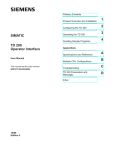
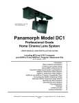
MEASURING AND ADJUSTING THE TEMPERATURE WITH CPU 224 PLC
AND TD 200 OPERATOR INTERFACE SIEMENS
Gabriel Nicolae Popa, Assoc. Prof. PhD. Eng., Faculty of Engineering Hunedoara, Politehnica
University Timişoara
Iosif Popa, Assoc. Prof. PhD. Eng., Faculty of Engineering Hunedoara, Politehnica University
Timişoara
Corina Maria Diniş, Lecturer PhD. Eng Faculty of Engineering Hunedoara, Politehnica University
Timişoara
Angela Iagăr, Lecturer PhD. Eng Faculty of Engineering Hunedoara, Politehnica University Timişoara
ABSTRACT: In the paper are presented two applications that perform the function of thermostat for measuring and
adjusting the temperature. Applications were made with CPU 224 PLC, extension modules EM 231 RTD and EM
235, and operator interface TD 200 (Siemens). Temperature measurement in both cases is made with a Pt 100
thermo-resistance (the resistance grows linearly with temperature). In both applications, it can view the operator
interface TD 200: current temperature, maximum temperature and minimum temperature that exceeded the required
value of temperature. For TD 200 operator interface configuration is presented.
At both applications it using a digital output of the CPU 224 PLC to connect or disconnect the power of the furnace
through a contactor (or electro-valve for gas). The article presents a comparative analysis between the two
programmes versions.
KEYWORDS: Adjust, measure, operator interface, PLC, temperature.
1. INTRODUCTION
Process control must be carried out with the help of
electronic devices that provide stability, accuracy and
decreases the length of the transient processes [1,4,6,8].
As a result of the rapid development of technology,
many of the problems have been solved through the use
of PLCs, and possibly through the use of a PC for
supervision. By using PLCs shrinks the number of
connections between devices (displays, motors, sensors,
switches, valves, etc.) and there is the possibility of
using communication tools, thus ensuring a high level
of service and high flexibility in controlling processes
[7,9,14].
In automated systems, PLCs represent the main part
of the management and control of the process. Through
the execution of a program stored in the program
memory, programmable machine monitors the status of
the process by the signals received from the input
devices. By building the program, PLC determines
actions on output devices. In the case of more complex
processes it is possible to connect several PLCs from a
PC [5,15].
Automatic management of industrial processes to
ensure both with general purpose PLCs type, and, also,
with specialized PLCs type. Examples of specialized
PLCs for industrial processes may be: automation
equipment for boilers and heating installations in
275
buildings, control and signalling equipment for the
detection and alarm, fire detection, driving pumping
stations and water supply of communities, etc. The
operative part orders send command to the system and
to the operative information about evolution is collected
under orders sent [2,3].
In the paper are presented two applications made
with PLC for the temperature measurement and
adjustment of industrial furnaces. The first application,
uses CPU 224 PLC [11], extension module EM 231
RTD (specialized for thermo-resistance connection)
[13], TD 200 operator interface [12] and thermoresistance Pt 100 [16]. The second application, use the
extension module EM 235 (with four analogue inputs
and one analogue output, 12 bit conversion); it is use
only one input and one analogue output [13]. The
analogue output is used to inject a constant current
(regardless of the temperature) through Pt 100. Due to
the change in temperature will change the voltage on Pt
100 that will be measured with the analogue input
module. For the second application, the program is
complicated because it converts the measured voltage
on the temperature displayed into TD 200 operator
interface.
2. PLCs. CPU 224 SIEMENS
PLCs are simple microcomputers that are built
specifically to deal with issues of combinational and
sequential programs. They are used to replace the
combinational and sequential automation made with
contacts and relays. In a general form PLC can be
considered as a piece of equipment that allows the
logical linkages between a large number of inputs and
outputs, without additional interfacing devices. [5,7,11].
These systems offer fewer characteristics than
process PCs, but can be used by less qualified staff due
to application-oriented languages. Carrying out a
program on such a system is synchronous. PLCs are
built specifically to operate in industrial environments,
with the necessary protections against environmental
pollution from industry and having interfaces adapted
for transducers and actuators elements most commonly
used in the industry. For more advanced applications,
there is currently high performance PLCs which
approaches the complexity of computers. The PLCs
work with words of 8, 16 and 32 bit and may perform
floating point arithmetic operations. PLC types
available on the market are spread, and their
characteristics are different from one manufacturer to
another.
The S7-200 PLCs (Siemens) is intended for lowcomplexity applications and includes several types of
central units. For a schedule of this series are required,
in addition to functionality, a PC computer,
programming Step 7 MicroWIN 32 and a
communication cable between the PC and PLC (PPI
port serial port on computer - PC/PPI). Siemens
manufactures and a new series of automatic small S7-22
x, equipped with communication facilities on the
network embedded in the central unit [11].
Table 1
The main characteristics of CPU 224 [11]
Battery backup
Yes
Communication port type
RS 485
SIMATIC S7-200
For use with
Series
Input type
Analogue, Digital
Manufacturer series
SIMATIC S7-200
Maximum baud rate
187.5 kbit/s
203 (168 Digital, 35
Maximum inputs/outputs
Analogue)
Maximum Operating
+45°C
Temperature
Minimum operating
0°C
temperature
Mounting type
Rack
Number of communication
1
ports
Number of I/O
24
Number of inputs
14
Number of outputs
10
Output current
750 mA
Analogue, Digital,
Output type
Transistor
Computer, SIMATIC
Programming interface
PG/PC
Programming language used STL, LAD, FBD
Scan time
0.22 μs
276
12 kB (Program
Memory), 8 kB (Data
Memory)
Voltage supply
20.4 → 28.8 V D.C.
Width
120.5mm
Depth
62mm
Length
80mm
An S7-200 PLC consists of a CPU module, alone or
with multiple extensions. CPU module is composed of a
central unit, power supply and input/output in a compact
structure. CPU module has a number of status LEDs
(SF/DIAG, RUN, STOP) and visualization of the status
of inputs and outputs.
Step 7 MicroWIN 32 is a software package for
programming and configuring PLCs Siemens S7-200
series. This software package allows set parameters for
hardware debugging, editing, and uploading in PLCs
programs developed.
Languages supported by Step 7 MicroWIN 32 are:
• STL, which is a text language consisting of usual
instructions list;
• LAD, which is a semi-graphic language, consisting of
objects, which is achieved through interconnection
circuits, called networks, which are similar to those
made with contacts and relays;
• FBD, is a semi-graphic language, consisting of
objects, which is achieved through interconnection
circuits called networks, which are similar to those
made with integrated circuits.
In principle, for any industrial application where is
used PLC using the following sequence of command
diagram [10]:
a. Process must be selected to be controlled. The system
automatically can be a machine or a process. Process
control is constantly supervised by input devices
(sensors) that transmit signals to the programmable
machine. When running the machine scheme, PLC
transmits signals to output devices (elements) that
determine the operating mode of the process. In order to
understand the functioning of the program it is
necessary to construct flowcharts.
b. It must set the devices that connect to the entry and
exit of programmable machine. Input may be connected
to different switches, sensors, etc. It can connect the
output coils, valves, electromagnetic valves, micromotors, relays, signal optical instruments and/or
acoustic, LEDs, etc.
c. Implementation of the programme with specific PLC
instructions according to the flowchart. The program
must be stored in the PLC programmable memory.
After the implementation of the programme, it is
necessary to detect program errors. Also, through the
program shall be provided for all possible situations that
may arise in the process. Before setting off for the first
time, the facility must be checked once all input and
output if are connected to the correct inputs and outputs
programmable machine. After connection of the power
supply voltage, the process begins to be controlled by
the PLC.
Total memory available
3. OPERATOR INTERFACE WITH ALPHANUMERIC DISPLAY TD200 SIEMENS
User label
Keys
TD200 (Text Display) is a operator interface with
text display designed specifically for the family S7-200
PLCs. Communication is done through the serial port by
using the PPI Protocol. The unit is powered either from
the mains to 24V from PLC (via special cable TD/CPU)
or from a separate voltage source (i.e. 230V, 50Hz)[12].
The most important functions of the TD 200 are:
• Display of read messages from AP S7-200;
• Adjusting the variables in the process;
• Possibility to control the process from the buttons F1F8;
• Ability to force/release values in input/output
registers;
• Possibility to set clock and date for S7-200 units that
have built-in clock function;
• Provides menus and messages in six languages.
TD200 interface works as master when it is connected
to one or more automated S7-200. TD200 is also
designed to operate together with other devices in the
network master.
Fig. 1. Operator interface TD200 Siemens
TD200 is a small, compact, providing all the
necessary elements for the creation of the PLC S7-200
CPU. Interface components are described in table 2.
Table 3 contains a description of the command keys and
table 4 describe the functions of the keys F1-F8.
Table 2
Operator interface components TD200 description
Component
Description
Text display
The display is illuminated and made
area
up of liquid crystal display (LCD)
with a resolution of 33x181 pixels.
It is used to view messages.
Communication
9-pin D connector for
port
communication with S7-200 PLC
with TD200 using the cable
provided TD/CPU.
Power
It can connect an external voltage
connection
source. This connection is not
required if is used the cable
provided TD/CPU.
TD/CPU cable
A serial cable is straight-trough 9pins used for communication with
PLC and power supply TD200
interface.
277
The label used to customize the
keys.
TD200 has nine keys. Five of them
performing and four built-in
functions can be used to perform
user-defined functions.
Fig. 2. Operator interface TD200 components
Table 3
Description of the command keys the operator interface
TD200
Command
Description
keys
ENTER
It is used to write data to the PLC and to
confirm (acknowledge) a message.
ESC
Is used to switch (toggle) between the
display of messages and menu mode or
to interrupt an edit.
Up arrow
It is used to increment a value or to
navigate upwards.
Down
It is used for a value or decrement to
arrow
navigate down.
SHIFT
Is used to modulate the functions of all
keys. When this key is touch will be
displayed blinking letter S in the lowerright corner.
Table 4
Description of the keys for user-defined functions
F1-F8 keys
Description
F1
F1 key bit sets the Mx 0. If is press
SHIFT + F1 set Mx. 4.
F2
F1 key bit sets the Mx 1. If is press
SHIFT + F1 set Mx. 5.
F3
F1 key bit sets the Mx 2. If is press
SHIFT + F1 set Mx. 6.
F4
F1 key bit sets the Mx 3. If is press
SHIFT + F1 set Mx. 7.
TD200 is a display device used for alpha-numeric
display of messages validated by the PLC S7-200 CPU.
TD200 interface programming is not necessary. The
only operating parameters stored in the memory are the
interface address TD200, S7-200 CPU address, baud
rate and location configuration block (called TD200
Block). This block is stored in the memory variable (V)
functionality. The interface configuration parameters as
language, TD200 discount rate, message and the
validation of the message bits are stored in the block
TD200. On start-up, it reads the configuration block
TD200 and verifies the accuracy of all parameters. If
everything is alright, start checking TD200 validation of
bits messages to determine what message is necessary to
display.
In the last dialog box will use the "Finish" button to
validate and save the block parameters and close the
configuration tool. To begin configuring it will press the
button "Next". The program Step 7 Micro/WIN is
equipped with a "special feature" (wizard) to ease the
Bloc's TD200 configuration and messages in the data
memory of the PLC S7-200. The selection options and
creating messages, wizard automatically writes TD200
block with parameters and text messages in TD200
window Data blocks. This block of data (Data Block)
and block containing TD200 can now be downloaded
(downloaded) in memory of the machine. This section
contains the procedure for creating a template. It will
use the following guidelines to create a block TD200
and two messages. The first message will contain the
text and data. The second message will require
acknowledgement (acknowledge) operator. To select the
Setup function of the interface it will select Tools
TD200 > Wizard. To navigate forward or backward, use
the buttons "Next" and "Previous". In the last dialog box
will use the "Finish" button to validate and save the
block parameters and close the configuration tool.
4. REALIZATION OF MEASURING AND
ADJUSTING TEMPERATURE APPLICATIONS
WITH PLC
In this chapter are presented two applications that
perform the function of thermostat for electric or gas
industrial furnaces. Applications were made with PLC
Siemens CPU 224, extension module EM 231 RTD (can
connect two temperature sensors of various types
configurable from switches) and EM 235 (4 analogue
inputs and one analogue output, voltage or current,
configurable from switches) [13], TD 200 operator
interface [12]. Temperature measurement in both
situations is made with Pt 100 thermo-resistance (100
ohm at 0°C) [16].
Fig.3. The laboratory equipment used in experiments
278
Fig.4. CPU 224 PLC and EM 235 and EM 231 RTD
extension modules
Fig.5. Pt 100 thermo-resistance used in experiments
(connected on a power resistor)
To check the operation of the programs have set the
temperature lower limit value at 22 °C, and for the
upper limit at 25 °C. While the Pt 100 temperature
measured is between 22 and 25 °C, it displays the
message 1. If the temperature is higher than the upper
limit, in addition to the message 1 a message 2 is
displayed. If the temperature is less than the lower limit,
in addition to the message 1 a message is displayed 3.
4.1. Measuring and adjusting the temperature with
Pt100 and EM 231 RTD module
The operation of this application is the thermostat
switch to the temperature thresholds, with the values
imposed by the program. The temperature and the
maximum and minimum values are displayed on the
operator interface TD 200 (Siemens). A digital output is
using the output Q0.0 that is 1 logical when the
temperature is lower than the lower value, or 0 logic
when the temperature exceeds the upper assessment
threshold. Output Q0.0 (electric contact), connects with
the coil of a contactor or electro-valve for command of a
three-phase power resistors (which produces heat) or a
servo-valve for the gas supply to a gas oven (fig. 6).
This application requires the following equipment:
- CPU 224 (Siemens);
- EM 231 2xAI RTD (Siemens);
- operator interface TD-200 (Siemens);
- thermo-resistance Pt 100;
- a power autotransformer, a contactor K that supply
the power resistance R.
The switches of EM 231 RTD were achieved the
following configuration (at the 8 switches) for Pt 100:
SW1 SW2 SW3 SW4 SW5 SW6 SW7 SW8
0
0
0
0
0 0
0
1
SW1-SW5 configures the type of thermo-resistance;
SW6 - 0 to measure the positive temperatures, 1 to
measure negative temperatures;
SW7 - 0 degrees Celsius, 1 degree Fahrenheit;
SW8 - 1 for thermo-resistances with 2 or 4 wire, 0 for
thermo-resistance with three conductors.
In this application, Pt 100 thermo-resistance
connects to EM 231 RTD:
- -a Pt100 connector at A- and a-;
- +a Pt100 connector at A+ and a+.
EM 231 RTD feeds from CPU 224 supply. CPU 224
connects to power supply single phase, 230V, 50 Hz,
CPU 224 has a internal switched mode power supply
24V. Is connected, also, an analogue module 235 EM
(four analogue inputs and one analogue output) with 12bit conversion. This module cannot be used at the first
application.
Program listing for application 1
Network 1 Setting the limits of the operating temperature of the
regulator
LD Prima_scanare
// In the first cycle of operation
// SM0.1=1
MOVD +0, VD260
// To delete the values in VW260 and
//VW262
MOVW +0, VW200
// Deleting the memory where it will be
// introduced AIW8 entry
MOVW +250, VW260
// The upper limit setting of regulator
// = 25°C; temp. value x 10
MOVW +220, VW262
// The lower limit setting of regulator
// = 22°C; temp. value x 10
Network 2 Calculating and validating the message 1
LD Tot_timpul_1
// SM 0.0 is logical 1 and determine
// program execution
MOVW AIW8, VW200
// The size of the analogue displacement
//measured (temperature) at the AIW8 in memory of VW200.
MOVW VW200, VW116 // Transfer result at VW116 (which is in
//connection with operator interf. TD 200) for displaying information.
S
V12.7, 1
// Message 1 validation to display
// TD 200.
Network 3 If the temperature exceeds the maximum value, it validates
the message and exit Q 0.0 are reset.
LDW>= VW200, VW260
//If the temperature is > = than the
//stored maximum temperature, VW260
= V 12.6
//it validates the message 2 and will be
//displayed on the TD //200.
R Q0.0, 1
// Q0.0=0 output (reset)
MOVW VW260, VW136
// Transfer the result to memory
//VW136 (who is in touch with TD 200
//operator panel) to display message 2.
Fig.6. Connection scheme of CPU 224 PLC, TD 200,
EM 231 RTD and power resistance R
Because the application uses the first entry of the
module EM 231 RTD, and before this module is
connected the module EM 235 (with four analogue
inputs), AIW8 input is used for temperature
measurement.
TD-200 operator interface displays the current value
of the temperature measured (1 message), overcoming
the higher set value (message 2) and minimum value set
(3 message). The program was developed in STL, but
can be viewed, also, on LAD or FBD. AIW8 is the
number 1 input of EM231 analogue module, and EM
235 module is connected before EM 231 RTD (which
has inputs AIW0, AIW2, AIW4, AIW6).
Fig.7. Connect the conductors to the first application
(with EM 231 RTD module)
279
Network 4 If the temperature falls below the minimum value, it
validates the message 3 and exit Q 0.0 sets.
LDW<= VW200, VW262
//If the temperature is the
//minimum temperature than < = stored in VW262,
=V12.5 //validating message 3 and will be displayed on the TD 200.
S
Q0.0, 1
// Q0.0=1 output (set)
MOVW VW262, VW156
// Transfer the result to memory
//VW156 (who is in touch with TD 200 operator panel) to display the
//message 3.
Network 5 End of programme
MEND
// End of programme.
Data Block for TD 200 configuration
// data block DB1 (V memory):
//
// The parameters block for TD200 for writing messages measured
//temperature values and to overcome the upper and lower limits.
// Configuration is done with specialized for TD 200Wizard
//in the STEP 7 Microwin
VB0 'TD'
// Operator panel identification TD 200
VB2 16#10
// English setting and up-dating fast
VB3 16#00
// Setting 20 characters; Button up V3.2;
// Button down V3.3
VB4 3
// Setting the number of messages: 3
VB5 0
// Setting the buttons and their association with
//memoirs M 0.0-M 0.7
VW6 100
// Setting memory addresses starting with VW100
VW8 12
// Setting addresses for validation bits VW12
messages
// Message 1
// Validation bit message 1 V12.7
VB100 'Temperatura = '
VB114 16#00
// No editing, no confirmation and no password;
VB115 16#31
// Word without a sign; a digit to the right of the
//decimal place;
VW116 16#0000 // Moving the date to be displayed.
VB118 'ßC'
// Message 1 ends.
// Message 2
// Validation bit message 2 V12.6
VB120 'Temperatura > '
VB134 16#00
// No editing, no confirmation and no password;
VB135 16#31
// Word without a sign; a digit to the right of the
//decimal place;
VW136 16#0000 // Moving the date to be displayed.
VB138 'ßC'
// Message 2 ends.
// Message 3
// Validation bit message 3 V12.5
VB140 'Temperatura < '
VB154 16#00
// No editing, no confirmation and no password;
VB155 16#31
// Word without a sign; a digit to the right of the
//decimal place;
VW156 16#0000 // Moving the date to be displayed.
VB158 'ßC'
// Message 3 ends.
//end configuration block TD 200.
Fig.8. Displaying the first message (current
temperature) on the operator interface TD 200
Fig.9. Displaying the first message (current
temperature) and the second (upper limit value being
exceeded) operator interface TD 200
4.2. Measuring and adjusting the temperature with
Pt100 and EM 235 module (4 analogue inputs and 1
analogue output) with 12-bit conversion
The operation of this application is the thermostat
switch to the temperature thresholds, with the values
imposed by the program. The temperature and the
maximum and minimum value of the temperature are
displayed on the operator interface TD 200 (Siemens).
A digital output is using Q0.0 that is 1 logical when the
temperature is lower than the lower value, or 0 logic
when the temperature is higher than the upper threshold
(fig. 11).
This application requires the following equipment:
- CPU 224 (Siemens);
- EM 235 (4xAI, 1xAQ, Siemens);
- operator interface TD-200 (Siemens);
- thermo-resistance Pt 100;
- a power autotransformer, a contactor K that supply
the power resistance R.
On the panoply of experimentations are three
connected modules: a PLC CPU224, an analogue
extension module EM 235 and another extension
module EM 231 2xRTD; last module in this application
shall not be used. CPU 224 is fed from single-phase
mains voltage (230 V, 50 Hz). The PLC has an internal
voltage source with a value of 24 V DC. From this
source is feeding EM 235 module. Output Q0.0 (contact
form), connects with the coil of a contactor or electrovalve for command of a three-phase power resistors
(which produces heat) or a servo-valve for the gas
supply to a gas-fired furnace. EM 235 is powered from
+ 24 V and the mass of the internal source of CPU 224.
In this application, it can use the analogue output in
the form of the current (maximum 20 mA, between M0
and I0 terminals) from which connects Pt 100 thermoresistance (100 ohm at 0 °C). Pt 100 is injected into a
constant current of 12.5 mA. With a 12.5 mA current
injected into the Pt 100 is obtained 5 mV/°C. If the Pt
100 change with temperature (increases with increasing
temperature), the voltage on the Pt 100 also increases.
By measuring the voltage on Pt 100, using AIW0 input
of EM 235 module, it can measure temperature with Pt
100. Modification of Pt 100 resistance is about 0.4
Ohms/°C.
Fig.11. Connection scheme of CPU 224 PLC, TD 200,
EM 235 and power resistance R
Fig.10. Displaying the first message (current
temperature) and the third (lower limit value being
exceeded) operator interface TD 200
280
Measurement range of Pt100 is usually between -60
and 400 °C. Resistant Pt 100 connects between M0 and
I0 (exit 235 EM module). The ends of thermo-resistance
connect to the first input (AIW0) EM 235 analogue
module. His Pt 100 connecting at the entrance of EM
235 is between A- (ground) and A +. AIW0 input is the
number 1 input from EM235 module which is used in
the application. Module EM 235 entries set the microswitches to measure single-polar voltages (10 V). At
switches EM 235 has achieved the following
configuration (at the 6 switches):
SW1 SW2 SW3 SW4 SW5 SW6
0
1
0
0
0
1
TD-200 operator interface displays the current value
of the temperature measured (1 message), exceeding the
higher set value (message 2) and exceeding the
minimum value set (3 message). The program was
developed in STL, but can be viewed and the LAD or
FBD (Siemens)
=V12.5 //validating message 3 and will be displayed on the TD 200.
S
Q0.0, 1
// Q0.0=1 output (set)
MOVW VW262, VW156
// Transfer the result to memory
//VW156 (who is in touch with TD 200 operator panel) to display the
//message 3.
Network 5 End of programme
MEND
// End of programme.
The data blocks to set up TD 200 is the same way as the
application 2.
Program listing for application 2
Network 1 Setting the limits of the operating temperature of the
regulator
LD Prima_scanare
// In the first cycle of operation
// SM0.1=1
MOVD +0, VD260
// To delete the values in VW260 and
//VW262
MOVW +0, VW200
// Deleting the memory where it will be
// introduced AIW8 entry
MOVW +250, VW260
// The upper limit setting of regulator
// = 25°C; temp. value x 10
MOVW +220, VW262
// The lower limit setting of regulator
// = 22°C; temp. value x 10
Fig.12. Connect wires for the second application
Network 2 Calculating and validating the message 1
LD Tot_timpul_1
// The bit SM0.0 is 1 logic and determine
//program execution
MOVW AIW0, VW200
// Moving the value of the input AIW0
// in the VW200.
-I VW252, VW200
// Substracting value for 0° C (offset)
// VW200-VW252.
DIV VW250, VD198
// The result of VD198 is divided in
// VW250 (for 1 ° C)
MUL +10, VD196
// The remainder is multiplied by 10.
DIV VW250, VD196
// Dividing the remaining value from
// VD196 to VW250 (1 ° C)
MOVW VW198, VW160 // The movement amount with a decimal
// place to the left
MOVW +0, VW198
// Deleting content from VW198.
MUL +10, VD198
// Multiplying the temperature measured
// with 10
+I VW160, VW200
// Result decimal place value roundup
MOVW VW200, VW116 // Transfer result in VW116 (which is in
//connection with operator panel TD 200)
S
V12.7, 1
// Message 1 validation
// for TD 200 display.
Network 3 If the temperature exceeds the maximum value, it validates
the message and exit Q 0.0 are reset.
LDW>= VW200, VW260
//If the temperature is > = than the
//stored maximum temperature, VW260
= V 12.6
//it validates the message 2 and will be
//displayed on the TD //200.
R Q0.0, 1
// Q0.0=0 output (reset)
MOVW VW260, VW136
// Transfer the result to memory
//VW136 (who is in touch with TD 200
//operator panel) to display message 2.
Network 4 If the temperature falls below the minimum value, it
validates the message 3 and exit Q 0.0 sets.
LDW<= VW200, VW262
//If the temperature is the
//minimum temperature than < = stored in VW262
281
Fig.13. Looking at the experience of the second
application
In the second application, the experiments connected
the mili-ammeter to be able to measure the constant,
regardless of the temperature, by Pt 100 thermoresistance. Constant current is generated by extension
module EM 235 (12.5 mA) (fig. 13).
4.3. Issues regarding the use of PLCs
The most significant disadvantages of classical
control systems (with relays and switches) are:
- high working time for connections between electrical
devices;
-the difficulty of replacement parts;
-difficulty in determining of faults;
-the need for the use of a qualified staff with practical
experience;
-the emergence cannot be determined the time of
elimination of the defect; usually this time is high, the
process must be stopped.
With the invention of PLCs, changed the way in
which the command installations; its occur a number of
advantages.
The advantages of using PLC in command
installations are:
- compared to classical control systems (with relays)
number of conductors needed to greatly reduce the
connections (generally 80%);
- power consumption is much lower due to the fact that
a PLC uses less electricity than a group of relays that
performs an equivalent function;
- fast determination and remedy the issues in the
system;
- rapid adaptation to different applications with
command systems with PLC by modifying the program
running in the PLC (no change of conductors for
connections, being only necessary to adapt certain
devices for input and output);
- the total size is reduced compared to conventional
equivalent facilities;
- command installations with PLCs are cheaper
compared to the classics, especially in the case of
installations with a large number of input devices and
output;
- safety in operation is greater in the case of orders
made with PLCs.
5. CONCLUSIONS
PLCs are used increasingly more often in the
industry. An application of those is temperature control
of industrial furnaces (e.g. for drying of painted
components) with electrically or gas heated.
PLC CPU 224 Siemens belongs to the category of
low-capacity general PLC. For use in measuring and
monitoring the temperature industrial furnaces have
utilized a specialized expansion module (EM 231 RTD)
or general (EM 235 4AI, 1AQ) together with PLC. Use
specialized extension module provides an easier
programming of PLC, but it can be used for a limited
range of applications.
The applications are based on operation of
thermostat with switch to two limits for temperature
(limits can be changed in the program). The current
temperature and the maximum value or the minimum
values are displayed on the TD 200. The values shown
are displayed with one decimal place.
282
The programs were implemented in STL, but due to
the programming environment (Step7 Microwin) can be
displayed in LAD and FBD.
6. REFERENCES
[1]. Andrei D., Georgescu I., Guran M. –
Automatizări în industria minieră, Editura
Tehnică, Bucureşti 1977.
[2]. Badea I. şi colectiv – Protectia prin relee şi
automatizarea sistemelor electrice, Editura
Tehnică, Bucureşti, 1973.
[3]. Groza V.R. – Analiza şi sinteza dispozitivelor
numerice,
Universitatea
“Politehnica”
Timişoara, 1995.
[4]. Poanta Aron, Pătrăşcoiu Nicolae – Circuite şi
echipamente electronice utilizate în industria
minieră, Editura Didactică şi Pedagogică,
Bucureşti, 1997.
[5]. Pop E., Leba M.C. – Microcontrolere şi
automate programabile, Editura Didactică şi
Pedagogică R.A., Bucureşti, 2003.
[6]. Popa G.N., Popa I. – Instalaţii electrice,
Editura Mirton, Timişoara, 2005.
[7]. Popa G.N., Popa I., Deaconu S. – Automate
programabile în aplicaţii, Editura Mirton,
Timişoara, 2006.
[8]. Popa I., Popa G.N. – Dispozitive electronice cu
structură cablată şi programată de protecţie a
motoarelor asincrone trifazate de joasă
tensiune, Editura Mirton, Timişoara 2000.
[9]. Toma L. – Sisteme de achiziţie şi prelucrare
numerică a semnalelor, Editura de Vest,
Timişoara, 1997.
[10]. Voloşencu C. – Standardizare şi metodologii
de proiectare în automatizări industriale,
Editura Matrix Rom, Bucureşti, 1998.
[11]. *** – Siemens S7-200 Programable Logic
Controller. User Manual, Siemens, 2003.
[12]. *** – Siemens TD 200 Operator Interface.
User Manual, Siemens, 2005.
[13]. http://www.automation.siemens.com/
[14]. http://www.control.com/
[15]. http://www.directindustry.com/
[16]. .http://www.ziehl.de/ziehl/englisch/temperatu
re_monitoring/5pt100sensoren_e.pdf