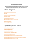
1
DrillMaster
Planter Drive Controller
Reference Manual
612366-03/12
Table of Contents
Description of Operation, Safety and Care . . . . . . . . . . . . . . 1
Installation . . . . . . . . . . . . . . . . . . . . . . . . . . . . . . . . . . . . 2-3
Tractor Controller Wiring Layout . . . . . . . . . . . . . . . . . . . . . 4
Console Functions . . . . . . . . . . . . . . . . . . . . . . . . . . . . . . . . 5
Calibration . . . . . . . . . . . . . . . . . . . . . . . . . . . . . . . . . . . . 6-8
Wiring Diagrams . . . . . . . . . . . . . . . . . . . . . . . . . . . . . . 9-12
Radar Options and Parts List . . . . . . . . . . . . . . . . . . . . . . . 13
Hydraulic Diagrams and Requirements . . . . . . . . . . . . 14-16
Description of Operation
The DrillMaster is designed to drive a Proportional Flow Control Valve using a PWM output. The valve
controls the flow to 1 to 3 hydraulic motors so it can be used with 1 to 3 section planters. All motors
are in series so they all rotate at the same speed and therefore they all apply the same amount of
seed. Three toggle switches (top of Console) turn the sections off, bypassing a motor, so the RPM of
the remaining motors do not change.
The DrillMaster operates as a “ground speed based controller” using a speed sensor input (from 1 of
the 3 sections) to maintain a target population of seed as ground speed varies. An external Module
is used to multiplex the flow signal so a different section is used when a section is turned off. Going
to Hold, turning all Sections Off, or zero speed will stop auto control and will also stop the PWM Valve
drive if “Auto Shut Off” is turned on (enabled). All sections are automatically turned off if the speed
goes to zero while in Auto mode. Seed flow is measured indirectly by measuring the seed drive shaft
RPM instead of counting seed. Drill Master also provides an early warning when seed bins are nearly
empty by flashing a “FILL” message.
Care and Maintenance of your DrillMaster
Store the console in a cool dry location if it will not be used for an extended period of time, such as
during the off-season. As with any electronic equipment, use care in cleaning so that water or other
liquids do not enter the case.
1
Installation
Mounting the Display Console
Select a mounting location which seems most
workable, and that best fits your needs. It
should be convenient to reach and highly visible
to the operator. DO NOT INSTALL IN A
POSITION THAT OBSTRUCTS THE VIEW OF
THE ROAD OR WORK AREA. Whenever
possible, avoid locations that expose the
console to direct sunlight, high temperature,
strong chemicals or rain. Place the mounting
bracket in selected location, mark hole, drill ¼”
(7mm) holes and mount bracket with bolts,
lockwashers and nuts provided. (Use selftapping screws if not practical to use bolts.) See
Illustration 1A. Put rubber washers on carriage
bolts and put the bolts through the bracket holes
from the inside out. Loosely attach the mount
knobs onto the bolts. Place console over
carriage bolt heads and tighten knobs to secure
the console. See Illustration 1B.
Attaching the Power and Run/Hold Control Switches
Mounting the Run/Hold Switch Kit
Remove the mount knob from either side of the
console. Install the bracket over the carriage
bolt and along side the console bracket. Install
the mount knob on the carriage bolt and tighten
to secure the console and run/hold switch
bracket in place.
4. Install the switch in the bracket and secure in
place with the remaining hex nut.
NOTE: Make sure the “ON connector is at
the top.
Install the switch into the bracket using the steps
below:
5. Attach the quick disconnects on the switch
harness to the switch. The RED wire should
attach to the top connection with the BLACK
attaching to the bottom connection.
1. Place the small washer on the switch
followed by the flat “notched” washer. See
Illustration 2.
6. Install the switch harness connector into the
mating connector (gray tie) on the console
harness.
2. Secure the washers in place with one of the
hex nuts.
NOTE: If using the included Power
On/Off switch instead of the
ignition switch connection, install
the power switch as described
above. Connect the power switch
cable connector (2 pin) to the
mating connector on the console
harness.
3. Peel the back from the decal and secure to
the front of the switch bracket.
See
Illustration 2.
2
Installation (continued)
Electrical Installation
This section explains how to connect your
DrillMaster to a 12-volt power source.
NOTE: The DrillMaster must be connected
to a 12 volt DC negative ground
electrical system.
ON/OFF SWITCH CONNECTION
The DrillMaster system uses P/N 14360 power
switch to turn the system on. If the P/N 14360
power switch is used, simply mount the switch
bracket as shown on page 4, and plug the
connector into the mating cable from the
console.
POWER/BATTERY CONNECTION
Locate the power cable for the DrillMaster and
route to the battery. When routing cable to
console, avoid areas where the cable may be
subjected to abrasion or excessive heat. Attach
the BLUE wire (ground) to a screw or bolt on the
equipment frame. See illustration 3. Be sure
there is a good metal-to-metal contact. Connect
the ORANGE wire to the positive battery
terminal. Connect the power to the DrillMaster
console by plugging the 2-pin W/P tower on the
power cable into the 2-pin W/P shroud of the
display console.
Attaching the Speed Sensor
The DrillMaster uses an Astro 5 GPS Speed
Sensor. The speed sensor always connects to
the 3-pin M/P connector with the yellow tie (on
the back of DrillMaster).
Speed calibration entered into the controller
must be 0.189.
3
DrillMaster Tractor Controller Wiring Layout
4
DrillMaster Console Functions
The DrillMaster features a large, easy-to-read liquid crystal display, easy-to-use rotary dial and lighted
panel for night use.
SECTION ON/OFF:
The Console has three Section
ON/OFF toggle switches on top
of the console. The toggle
switches turn planter sections
on and off directly and also
signal the Console which
sections are on or off.
AREA TOTALS (1) (2) (3):
Keeps a running count of the
total acres worked. May be
reset.
NOTE: WEIGHT and AREA
counter work in pairs, if
WEIGHT counter 1 is reset, it
also resets AREA counter 1).
WEIGHT TOTALS (1) (2) (3):
Displays total seed applied.
May be reset.
NOTE: WEIGHT and AREA
counters work in pairs, if
WEIGHT counter 1 is reset, it
also resets AREA counter 1).
DISTANCE:
Displays distance traveled in
feet. May be reset.
WEIGHT / MINUTE:
Displays 1000's of
dispensed per minute.
seed
AREA / HOUR:
Displays calculated Acres/Hour.
RATE:
Displays application rate in
1000's of seed / acre.
METER RPM:
Displays Seed Drive Shaft RPM.
SPEED:
Displays ground speed in miles
per hour.
WARNING LIGHT:
Indicates over or under application of 10% of
the Target Rate in AUTO or Loss of Sensor
Signal in Man. Also lit when in CAL.
5
Singulated Seed Planting with the DrillMaster
The DrillMaster will also control the planting of singulated seeds. The target rate will be the seed population,
displayed in thousands of seeds per acre. The Meter Cal is specific to the cells on a seed disc and will not
change.
DrillMaster Controller Calibration for singulated seed meters:
1. Turn all section switches off and put system in hold.
ROWS/SECTION:
Enter the # of SEED METERS per section. For a twin
2. Press CAL for one (1) second to enter calibration
row configuration, each twin row has 2 seed meters.
mode. Red light will be on steady and CAL will be
This displays the rows per section for the section
displayed in CAL mode.
selected. Unused sections must be programmed to
zero rows. The DrillMaster can have up to three
NOTE: You cannot enter CAL without RUN/HOLD
sections.
switch in hold.
NOTE: The controller must be out of HOLD and be in
3. Turn the dial to the items listed below and set as
RUN to enter rows/section. Turn section one
instructed. Numbers can be changed by using the
on while the other two sections are off. The
“+” or “-“ buttons.
corresponding section icon 1 will turn on and
the number of rows in the section can then be
4. When complete, press CAL for one (1) second to
adjusted. After section one is entered, turn it
exit CAL mode. Red light should go out and CAL will
off and turn section two on, then turn two off
not be displayed. You MUST exit Calibration mode
and turn the section 3 on and adjust. When
to save your setting.
finished, turn the DrillMaster back to hold and
the screen will display no SECtn. If you are on
METER CAL: Enter the Meter Cal for the seed
a single or two section planter, the sections not
meter you are using from the chart below.
being used must be set to 0 rows.
Number of seed
Meter Cal
SPEED CAL:
cells
in DrillMaster
For the ASTRO 5 which is included with the DrillMaster,
in seed meter
this setting should be .189.
30
2000
CAL TEST:
36
1667
This is not a true “Calibration Factor” but rather a
method of testing the planter to confirm the seed meter
40
1500
dispenses the correct number of seeds.
45
1333
Prior to using CAL TEST for singulated seeds, it is
46
1304
recommended to change the sample size that will be
dispensed. After exiting the CAL mode, and red light is
50
1200
off.
56
1071
1. Turn DrillMaster Off
60
1000
2. Hold down AUTO/MAN and CAL buttons while
64
938
turning DrillMaster on. “Spec” will show on disp;ay
90
667
briefly.
108
556
Formula: Meter Cal = 60 pulses a revolution
÷ number of seed cells
x 1000
ROW SPACING:
Enter the AVERAGE row spacing in inches of your
implement. For example, on a 38" twin row planter, you
would enter the average row spacing of 19".
ADJUST RATE:
Enter the value for the disired amount of change in
thousand seeds/acre to be used for making on the go
rate adjustments.
TARGET RATE:
Enter the desired planting rate in thousand seeds/acre.
6
3. Push CAL until “1" shows in display.
4. Turn dial to DISTANCE/SPEED CAL position.
5. Default value is 1.00, which will dispense 1,000
seeds per meter. We recommend you change this
value to 0.150, which will dispense 150 seeds/meter.
6. Push CAL until red light goes off and CAL is not
shown on the display.
TEST SPEED:
This is also not a true “Calibration Factor”. TEST
SPEED along with CAL TEST will be used in the PrePlanting Seed Calibration Process.
Pre-Season Test
This test should be done prior to every planting season. You will have to have the implement hooked to
tractor with hydraulics available. The tractor will remain stationary.
1. This test should be done after completing the
INITIAL SETUP on page 6.
2. Turn power toggle to ON position, and
RUN/HOLD toggle to HOLD.
3. Enter CAL mode by pushing and holding CAL
soft key until red warning light is steady on.
4. Turn center rotary switch to TEST SPEED. Use
+ or - soft key to adjust speed you plan to run in
the field.
(Example: 5.0 mph)
9. Now that motors are running, put center rotary
switch on METER RPM and you should have a
rpm reading on the display. Shut off Section
toggle switches one by one and you should
continue to get a rpm reading until the last section
is shut off. This verifies that all shaft sensors and
poppet valves on motors are working.
10. With everything still running, turn all Section
toggles ON that are being used. Switch to HOLD.
11. Push and hold CAL to get out of calibration.
12. Push AUTO/MAN button to enter manual mode.
5. Turn hydraulics on.
13. Move center rotary selector to RATE.
NOTE: There is a check valve on the hydraulic
hoses which prevents the motors from
running backwards. However, on initial
start up they may momentarily run
backwards.
14. Switch RUN/HOLD toggle to RUN.
15. Push and hold “+” soft key. Hydraulic motors
should speed up to maximum speed.
6. Push AUTO/MAN soft key so AUTO is displayed
on screen.
16. Push and hold “-“ soft key. Hydraulic motors slow
down to almost a stop.
7. Make sure all necessary Section toggles are in
the ON position.
17. This verifies the PWM valve is working properly.
8. Put RUN/HOLD switch to RUN. Lower planter to
activate mercury switch. Hydraulic motors should
now be running; if not, make sure hydraulics is
selected in correct direction and Section switches
are on.
7
Singulated Seed Planting with the DrillMaster
Seed Meter Test Process
(Using CAL TEST function)
This procedure is used prior to field operation. These steps will verify the DrillMaster and your seed
meter dispenses the correct number of seeds.
Preparation
1. Fill planter with enough seed to fill meter.
2. Position catch container under each seed tube.
Enter Calibration Mode
(switch controller to hold and press the “CAL” button until the red light is solid).
1. Turn Rotary Position Switch to “Cal Test”, “Off” appears in the display, press “+” to activate the
Calibration Test mode. .150 appears in the display to dispense a 150 seed sample. To set sample
size, see singulated seed calibration.
2. Turn rotary position switch to “Test Speed”.
3. Use “+” to enter normal operating speed.
4. Turn rotary position switch back to “Cal Test”.
5. Switch from the hold to the run position and turn all sections on. The “Cal Test” will begin. The
display will count up the measured sample size and automatically turn off at 150 seeds.
6. Count the seeds to verify proper operation and calibration.
7. Press and hold “CAL” until red light is off to exit calibration.
If the proper number of seeds is not dispensed:
1. Check “Meter Cal”.
2. Is the meter drive shaft speed sensor properly aimed at 60 tooth target (1/16 - 1/8" clearance).
3. Is meter and vacuum level adjusted properly.
In-Field Operation in AUTO Mode
1. Switch on tractor hydraulics.
2. Turn on all Section switches located on the top of the DrillMaster controller.
3. Push AUTO/MAN button until AUTO is displayed on DrillMaster display screen.
4. Switch RUN/HOLD toggle switch to RUN.
5. DrillMaster controller and planter hydraulic drive should now be ready for AUTO field operation.
Planter should now operate only when planter is down and tractor is moving.
8
Single Section System Diagram
9
Multi-Section System Diagram
10
DrillMaster Wiring Diagram
Single Section
11
DrillMaster Wiring Diagram
Multi Section
12
SPEED CAL Numbers
for various radar models or GPS speed sensors
Radars
Cal No.
Hz / MPH
Vansco
.150
58.90
Raven
.148
59.80
Magnavox
.154
57.40
Dickey-John
.149
58.94
Dickey-John
.199
44.21
Dickey-John
.319
27.64
Dickey-John
.518
17.034
GPS Speed
Cal No.
Hz / MPH
Astro 5
.189
46.56
SkyTrak (Std)
.150
58.94
SkyTrak (MT)
.910
9.82
Dickey-John
.210
42.00
John Deere
.197
44.70
³ Shipped with DrillMaster
Part No.
Description
607119
Bin Level Kit
609511
ASTRO V GPS Speed Sensor
609529
Multiplexer Module, Multiple Section
609537
Gear Tooth Sensor, CHERRY
609545
PWM Hydraulic Control Valve
609552
10' Extension Cable, 10 Pin
609560
Mercury Switch, Implement Mounted RUN/HOLD
609578
Hydraulic Motor with Shut Off, 4.9 CID, CCW
610634
Mounted Drill Kit
610931
Single Section Drill Kit
433037
#40 Sprocket 14 Tooth
954149
#40 Sprocket 30 Tooth
935080
#2050 Sprocket 20 Tooth
971572
#2050 Sprocket 30 Tooth
473694
Hydraulic Check Valve-.750-16 SAE
971606
60 Tooth Adjustment Handle
13
Hydraulic Circuit
14
Determining Hydraulic Motor Rotation
Motor rotation must turn the seed shaft of the planter counter-clockwise when viewed from the left end
of the planter
Motor rotation is determined by looking into the shaft end of the motor.
For counter-clockwise rotation oil should flow into port marked 2, out port 1, into the next motor in the
series or back to the bypass port tee fitting on the PWM valve.
The ON-OFF solenoid valve must be mounted in the cavity next to the in port.
Reverse ports and solenoid valve for clock-wise rotation.
Photo show motor configured for counter-clockwise rotation.
15
Tractor Hydraulic Requirements
The hydraulic drive motors require a maximum of 7 gallon per minute of hydraulic oil at a maximum
pressure of 1500 psi. Average oil requirement is usually less then 5 gallon per minute.
With minor modification the drive PWM valve will function with a tractor equipped with a closed or open
center hydraulic system. Contact your tractor dealer to determine which hydraulic system your tractor
may have. Most recently manufactured tractors are equipped with a closed center hydraulic system.
The PWM valve is shipped with the closed center cavity plug installed.
Tractors with open center system:
Tractors with closed center system:
1. When running in series with another
hydraulic motor, such as a planter fan motor.
The SureFire valve must allow all oil going
through the fan to pass through it. The
SureFire valve will be ‘open center’ and
divert the necessary oil to the SureFire
hydraulic motor.
1. When running this valve by itself from a
tractor hydraulic remote. By running closed
center, the SureFire valve will use the
minimum amount of oil and cause the least
oil circulation and heating. This leaves the
most oil for other hydraulic functions.
2. When running in series with two SureFire
valve/motor combinations.
This might
happen in the case of two seed drives or two
pumps. Each valve needs to let excess oil
pass through so the second valve has plenty
of oil to accomplish its necessary task.
Install this #10 MB plug to
run open center. Valve will
allow all oil to pass through
it, then divert necessary oil
to the hydraulic motor.
16
2. When running off power beyond hydraulic
ports, the valve must be closed.
Install this cavity plug to run
closed center. Valve will allow
all oil motor needs to pass
through.
P.O.Box 1438
Dodge City, Kansas 67801
(620) 227-7106