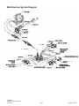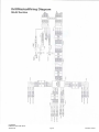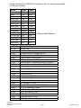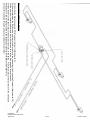
1
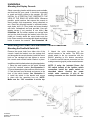
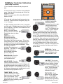
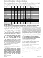
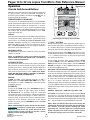
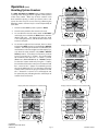
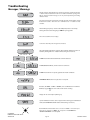
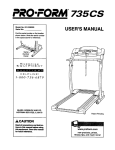
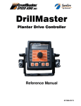
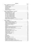
DrillMaster Grain Drill Section Controller REFERENCE MANUAL 611327-11/10 TABLE OF CONTENTS Description of Operation, Safety and Care..................................................3 Installation....................................................................................................4 Console Functions.......................................................................................7 Calibration....................................................................................................8 Operation....................................................................................................13 Troubleshooting..........................................................................................18 Wiring Diagrams.........................................................................................23 Radar Options and Parts List.....................................................................27 Hydraulic Diagrams and Requirements......................................................28 Fertilizer Calibration....................................................................................31 Singulated Seed Planting............................................................................33 CrustBuster DrillMaster Quick Start Guide 346-001150 Pg 2 Revised 11/2010 Description of Operation The DrillMaster is designed to drive a Proportional Flow Control Valve using a PWM output. The valve controls the flow to 1 to 3 hydraulic motors so it can be used with 1 to 3 section grain drills. All motors are in series so they all rotate at the same speed and therefore they all apply the same amount of seed. Three toggle switches (top of Console) turn the sections off, bypassing a motor, so the RPM of the remaining motors do not change. The DrillMaster operates as a “ground speed based controller” using a speed sensor input (from 1 of the 3 sections) to maintain a target lbs/acre of seed as ground speed varies. An external Module is used to multiplex the flow signal so a different section is used when a section is turned off. Going to Hold, turning all Sections Off, or zero speed will stop auto control and will also stop the PWM Valve drive if “Auto Shut Off” is turned on (enabled). All sections are automatically turned off if the speed goes to zero while in Auto mode. Seed flow is measured indirectly by measuring the seed drive shaft RPM instead of counting seed. The drill uses a one-point adjustable seed cup that is recognized as the most accurate and trouble free available for a wide variety of agricultural seeds. DrillMaster also provides an early warning when seed bins are nearly empty by flashing a “FILL” message. CrustBuster DrillMaster Quick Start Guide 346-001150 Pg 3 Revised 11/2010 Installation Mounting the Display Console Select a mounting location which seems most workable, and that best fits your needs. It should be convenient to reach and highly visible to the operator. DO NOT INSTALL IN A POSITION THAT OBSTRUCTS THE VIEW OF THE ROAD OR WORK AREA. Whenever possible, avoid locations that expose the console to direct sunlight, high temperature, strong chemicals or rain. Place the mounting bracket in selected location, mark holes, drill 1/4” (7mm) holes and mount bracket with bolts, lockwashers and nuts provided. (Use selftapping screws if not practical to use bolts.) See Illustration 1A. Put rubber washers on carriage bolts and put the bolts through the bracket holes from the inside out. Loosely attach the mount knobs onto the bolts. Place console over carriage bolt heads and tighten knobs to secure the console. See Illustration 1B. Attaching the Power and Run/Hold Control Switches Mounting the Run/Hold Switch Kit Remove the mount knob from either side of the console. Install the bracket over the carriage bolt and along side the console bracket. Install the mount knob on the carriage bolt and tighten to secure the console and run/hold switch bracket in place. Install the switch into the bracket using the steps below: 1. Place the small washer on the switch followed by the flat “notched” washer. See Illustration 2. 2. Secure the washers in place with one of the hex nuts. 3. Peel the back from the decal and secure to the front of the switch bracket. See Illustration 2. 4. Install the switch in the bracket and secure in place with the remaining hex nut. NOTE: Make sure the “ON” connector is at the top. CrustBuster DrillMaster Quick Start Guide 346-001150 Pg 4 5. Attach the quick disconnects on the switch harness to the switch. The RED wire should attach to the top connection with the BLACK attaching to the bottom connection. 6. Install the switch harness connector into the mating connector (gray tie) on the console harness. NOTE: If using the included Power On/ Off switch instead of the ignition switch connection, install the power switch as described above. Connect the power switch cable connector (2 pin) to the mating connector on the console harness. Revised 11/2010 Installation (continued) ON/OFF SWITCH CONNECTION Electrical Installation This section explains how to connect your DrillMaster to a 12-volt power source. NOTE: The DrillMaster must be connected to a 12volt DC negative ground electrical system. The DrillMaster system uses P/N 14360 power switch to turn the system on. If the P/N 14360 power switch is used, simply mount the switch bracket as shown on page 4, and plug the connector into the mating cable from the console. POWER/BATTERY CONNECTION Locate the power cable for the DrillMaster and route to the battery. When routing cable to console, avoid areas where the cable may be subjected to abrasion or excessive heat. Attach the BLUE wire (ground) to a screw or bolt on the equipment frame. See Illustration 3. Be sure there is a good metal-to-metal contact. Connect the ORANGE wire to the positive battery terminal. Connect the power to the DrillMaster console by plugging the 2-pin W/P tower on the power cable into the 2-pin W/P shroud of the display console. Installation (continued) Attaching the Speed Sensor The DrillMaster uses an Speed Sensor. The speed connects to the 3-pin M/P the yellow tie (on the back Astro 5 GPS sensor always connector with of DrillMaster). Speed calibration entered into the controller must be 0.189. CrustBuster DrillMaster Quick Start Guide 346-001150 Pg 5 Revised 11/2010 DrillMaster Tractor Controller Wiring Layout To Battery To Astro 5 (Yellow Tie) To Run/Hold Switch (Gray Tie) (Controller to Hitch) 10 Pin Harness on Drill CrustBuster DrillMaster Quick Start Guide 346-001150 Pg 6 Revised 11/2010 DrillMaster Console Functions The DrillMaster features a large, easy-to-read liquid crystal display, easy-to-use rotary dial and lighted panel for night use. AREA TOTALS (1) (2) (3): Keeps a running count of the total acres worked. May be reset. (Note: WEIGHT and AREA counters work in pairs, if WEIGHT counter 1 is reset, it also resets AREA counter 1). SECTION ON/OFF: The Console has three Section ON/Off toggle switches on top of the console. The toggle switches turn drill sections on and off directly and also signal the Console which sections are on or off. DISTANCE: Displays distance traveled in feet. May be reset. METER RPM: Displays Seed Drive Shaft RPM. WEIGHT TOTALS (1) (2) (3): Displays total product lbs. applied. May be reset (Note: WEIGHT and AREA counters work in pairs, if WEIGHT counter 1 is reset, it also resets AREA counter 1). SPEED: Displays ground speed in miles per hour. WEIGHT/MINUTE: Displays lbs. of product dispensed per minute. WARNING LIGHT: Indicates over or under application of 10% of the Target Rate in AUTO or Loss of Sensor Signal in Man. Also lit when in CAL. AREA/HOUR: Displays calculated Acres/Hour. RATE: Displays application rate in lbs./acre. CrustBuster DrillMaster Quick Start Guide 346-001150 Pg 7 Revised 11/2010 DrillMaster Controller Calibration Initial Setup Procedure 1.Turn all section switches off and put system in hold. 2. Press CAL for one (1) second to enter calibration mode. Red light will be on steady and CAL will be displayed in screen. NOTE: You cannot enter CAL without RUN/HOLD switch in HOLD. 3.Turn the dial to the items listed below and set as instructed. Numbers can be changed by using the “+“ or “-” buttons. 4. When complete, press CAL for one (1) second to exit CAL mode. Red light should go out and CAL will not be displayed. You MUST exit Calibration mode to save your settings. NOTE: It is a good idea to go back into CAL mode and recheck the values you have entered. METER CAL: Enter the starting calibration number from the Hydraulic Drive Meter Cal Chart on next page. To find your correct starting CAL number, choose the crop you are drilling and your slot opening, and enter the number from the chart into the DrillMaster. These are starting calibration numbers for average seed properties. The Meter Cal will be adjusted later in the DrillMaster calibration process. (Page 10.) ROW SPACING: Enter the row spacing in inches of your implement here. ADJUST RATE: Enter the value for the desired amount of change in lbs./acre to be used for making on the go rate adjustments when operating in AUTO. For example, if a value “1.0” is entered, you will be able to increase or decrease your seeding rate in one-lb. increments during operation in AUTO. TARGET RATE: Enter the value for the desired or Target Rate in lbs./acre. It can range from 0.00 to 99,999. This is the seeding rate the console will lock onto when operating in AUTO. CrustBuster DrillMaster Quick Start Guide 346-001150 ROWS/SECTION: This displays the rows per section for the section selected. Sections numbered from left to right. Unused sections must be programmed to zero rows. The DrillMaster can have up to three sections. NOTE: The controller must be in RUN and drill openers must be lowered to enter rows/section. Turn section one on while the other two sections are off. The corresponding section icon 1 will turn on and the number of rows in that section can then be adjusted. After section one is entered, turn it off and turn section two on, then turn two off and turn the section three on and adjust. When finished, turn the DrillMaster back to hold and the screen will display no SECtn. If you are on a single or two section drill, the sections not being used must be set to 0 rows. SPEED CAL: For the ASTRO 5 which is included with the DrillMaster, this setting should be .189. CAL TEST: This is not a true “Calibration Factor” but rather a method of testing the drill to determine the most accurate METER CAL factor. This will be used in the Pre-Planting Seed Calibration Process. TEST SPEED: This is also not a true “Calibration Factor”. TEST SPEED along with CAL TEST will be used in the Pre-Planting Seed Calibration Process. Pg 8 Revised 11/2010 Hydraulic Drive Meter Calibration Numbers These are starting calibration values. They can be refined for your drill and seed using the Pre-Planting Seed Calibration Process or the In-Field Seed Calibration Process. Crop Slot Width ALFALFA 1/8” 3/16” 12638 1/4” 3/8” 1/2” 5/8” 3/4” Suggested Sprocket Set C-D 7222 17-44 BARLEY 5857 4747 3956 CORN 10677 7909 6280 17-44 COTTON 7909 6673 5338 17-44 10677 8213 CANOLA 10920 8126 FESCUE 5460 12-44 14236 MILLET 16177 10400 7663 MILO 14444 10111 5321 17-30 17-44 17-44 17-44 OATS 11868 9020 6731 30-25 PINTO BEANS 8986 6787 5696 17-44 RICE 6664 5308 4539 17-44 RYE 4606 3600 2796 17-44 6960 5220 4176 30-25 4107 3286 2738 17-44 SOYBEAN 10103 WHEAT Pre-Season Test This test should be done prior to every planting season. You will have to have the implement hooked to tractor with hydraulics available. The tractor will remain stationary. 1. This test should be done after completing the INITIAL SETUP on Page 8. 2. Turn power toggle to and RUN/HOLD toggle ON to position, HOLD. 3. Enter CAL mode by pushing and holding CAL soft key until red warning light is steady on. 4. Turn center rotary switch to TEST SPEED. Use + or - soft key to adjust speed you plan to run in the field.(Example: 5.0 mph) 5. Turn hydraulics on. NOTE: There is a check valve on the hydraulic hoses which prevents the motors from running backwards, however on initial start up they may momentarily run backwards. 6. Push AUTO/MAN soft key so AUTO is displayed on screen. 7. Make sure all necessary Section toggles are in the ON position. 8. Put RUN/HOLD switch to RUN. Lower drill openers to activate mercury switch. Hydraulic motors should now be running, if not, make sure hydraulics is selected in correct direction and Section switches are on. Refer to Troubleshooting Section if motors still fail to operate. CrustBuster DrillMaster Quick Start Guide 346-001150 9. Now that motors are running, put center rotary switch on METER RPM and you should have a rpm reading on the display. Shut off Section toggle switches one by one and you should continue to get a rpm reading until the last section is shut off. This verifies that all shaft sensors and poppet valves on motors are working. 10. With everything still running, turn all Section toggles ON that are being used. Switch to HOLD. 11. Push and hold CAL to get out of calibration. 12. Push AUTO/MAN button to enter manual mode. 13. Move center rotary selector to RATE. 14. Switch RUN/HOLD toggle to RUN. 15. Push and hold “+” soft key. Hydraulic motors should all the way up to maximum speed. 16. Push and hold “-” soft key. Hydraulic motors slow down to almost a stop. 17. This verifies the PWM valve is working properly. If hydraulic motors do not speed up or slow down refer to Troubleshooting Section. 18.You are now ready to perform a CAL TEST before going to the field. Pg 9 Revised 11/2010 Pre-Planting Seed Calibration Process (using CAL TEST function) This procedure is used prior to field operation. These steps will determine a more accurate Meter Cal value for your exact drill settings with your seed. Preparation for Calibration The hydraulic drive motors have a speed range of 45 rpm to 405 rpm therefore if the required speed they must run to obtain rate is outside this range the red warning light will blink. To change the motor speed the sprockets on the end of each drill box may need to be changed. The following procedure will help you determine the correct sprockets for your seeding rate and drilling speed. 1. Put RUN/HOLD toggle to HOLD. 2. Push and hold CAL soft key until red light is steady on. 3. Turn center rotary switch to TARGET RATE and set to your desired seeding rate. 4. Turn center rotary switch to METER CAL and enter the calibration number for the crop and slot width you will be using.(See Page 9.) 5. Turn center rotary switch to TEST SPEED and set the speed you will be planting.(Example: 5.5 mph.) 6. Turn on hydraulics to drive motors. Lower drill openers so the run/hold mercury switch on drill openers is in run. Turn RUN/HOLD toggle on Drillmaster to RUN. Drive motors should now be operating. 7. Turn center rotary switch to METER RPM and note drill hex seed shaft rpm. Also note if red warning light on Drillmaster is blinking. 8. Refer to chart of sprockets and shaft RPM shown below. The red warning light blinking indicates the drive motors could not run fast enough to achieve the desired TARGET RATE. Compare the sprockets currently on the drill box end (SEE PAGE 13) with the sprockets listed in the table below. If the METER RPM noted during Step #7 is near the maximum motor speed for that sprocket combination then move down the sprocket chart to the next combination of sprockets, install these sprockets on the drill drive, rerun the above test and repeat the process until an acceptable motor speed is achieved. SPROCKETS ON END OF DRILL Jackshaft Sprocket on Sprocket-C Hex Seed Shaft-D 17 Tooth 44 Tooth 17 Tooth 30 Tooth 30 Tooth 44 Tooth 25 Tooth 30 Tooth 30 Tooth 25 Tooth 44 Tooth 30 Tooth 30 Tooth 17 Tooth 44 Tooth 17 Tooth HEX SEED SHAFT SPEED-MIN. and Max. Minimum 45 RPM Maximum 405 RPM Motor Speed Motor Speed 6 55 9 81 11 97 13 118 19 171 23 209 28 249 42 374 <<Most common sprocket ratio. <<Sprocket Ratio used for high soybean rates. 9. You should now have the proper sprocket combination to run an accurate calibration process. CrustBuster DrillMaster Quick Start Guide 346-001150 Pg 10 Revised 11/2010 Pre-Planting Seed Calibration Process (using CAL TEST function) Continued 10. Set the slot opening on each drill section for the desired crop. 11. Pour several pounds of seed over seed drops which will be used. It is recommended to sample at least two drops per drill section. Disconnect these drop tubes and position a catch container under each seed tube. NOTE: The more seed drops sampled per section the more accuracy you can expect from this test. Accuracy of plus or minus 4 to 6% is a very acceptable test. If you do not run a calibration test the standard calibration numbers (Page 9.)have an accuracy of plus or minus 10% at best Calibration Mode 1. Turn Power toggle to ON and RUN/HOLD toggle to HOLD. Turn all Section toggles on that you wish to test. 2. Enter CAL mode by pushing and holding the CAL soft key until red light is on steady. 3. Move center rotary switch to METER CAL and verify that the cal number is correct for crop and slot width you are testing.(See Page 9.) 4. Move center rotary switch to CAL TEST and push + soft key activate. Display should now show 1.00. A one pound test sample will be dispensed from each seed drop. 5. Move center rotary switch to TEST SPEED and use + or - soft key to select a speed that is close to the speed you plan to operate in the field. NOTE: Test speed must be the last data entered before starting calibration test. 6. Turn on hydraulics and move RUN/HOLD toggle to RUN. The motors should now run until one pound of seed is dispensed. Do not switch RUN/HOLD to HOLD or you will not be able to complete Step # 8. NOTE: The motors will automatically stop after one pound. 7. Gather samples caught into one pre-weighed container and weigh with scale provided with drill. Subtract weight of container from total weight then divide by number of seed drops caught. This is your actual sample size caught. 8. At the Drillmaster controller move the center rotary switch to CAL TEST. It should still show 1.00 on the display. Use the + or - soft keys to adjust display to actual sample size caught. NOTE: This is adjusting the METER CAL number at the same time so a high calibration number may take some time to adjust. 9. Once adjusted, put RUN/HOLD toggle to HOLD and push and hold CAL soft key until red light is no longer steady on. The new calibration number should now be saved. 10. Push and hold CAL soft key until red light is steady on. Move center rotary switch to METER CAL. Write down this new meter cal number for your drill slot width and seed.(Space provided on Page 13.) It is recommended to re-run the calibration test to verify accuracy of results. CrustBuster DrillMaster Quick Start Guide 346-001150 Pg 11 Revised 11/2010 Pre-Planting Seed Calibration Process (using CAL TEST function) Continued 11. Note that the Drillmaster controller is not counting any seed but merely calculating a rate based on row width and pulses from seed shaft sensor. The data entered in initial setup (Page 8), like row width and rows per section, is very important to the operation of the controller. This data should be checked periodically to ensure its accuracy. 12. Your Drillmaster controller should now be ready to go to the field. In-Field Seed Calibration Process This procedure will be used to find a more accurate Meter Cal value during normal field operation. You could place a known weight of seed in the drill and drill until it is gone during this process. If you have access to a scale, you could weigh the drill full of seed, then after drilling some amount. You will need to use some procedure to determine the actual weight of seed dispensed. 1. Clear a weight counter by selecting the Weight position and pressing “-“ key for 1 second while in HOLD. 2. Operate the drill in the field. The measured seed weight will accrue in the weight counter you reset in step 1. 3. Find the total actual weight of seed dispensed. 4. Enter Calibration mode by pressing CAL for 1 second. Red light will come on steady. 5. Turn dial to the METER CAL position. The current METER CAL will be displayed. 6. Push CAL key to toggle to the weight. Use the “+” and “-“ buttons to adjust the weight to the actual weight drilled. The DrillMaster will automatically change the METER CAL value. 7. Push CAL key to toggle back to the new METER CAL value. Make a note of the new value in your operators manual for future reference. 8. Press and Hold “CAL” until red light is off to exit calibration. This saves the new calibration settings. CrustBuster DrillMaster Quick Start Guide 346-001150 Pg 12 Revised 11/2010 Table to Record Your Own Data and Calibration Numbers CROP TYPE SLOT WIDTH TARGET CAL NUMBER RATE JACKSHAFT SPROCKET ON HEX SPROCKET-C SEED SHAFT-D Sprocket Locations In-Field Operation in AUTO Mode 1. Switch on tractor hydraulics. 2. Turn on all Section switches located on the top of the Drillmaster controller. 3. Push AUTO/MAN button until AUTO is displayed on Drillmaster display screen. 4. Switch RUN/HOLD toggle switch to RUN. 5. Drillmaster controller and drill hydraulic drive should now be ready for AUTO field operation. Drill should now operate only when openers are down and tractor is moving. CrustBuster DrillMaster Quick Start Guide 346-001150 Pg 13 Revised 11/2010 Pages 14 to 22 are copies from Micro-Trak Reference Manual Illustration 10 Operation DrillMaster Console Switches and Buttons MANAUTO CALHOLD V 1 2 3 4 Make sure your system is properly calibrated before beginning to apply product. We also recommend completion of Pre-Field System Checkout described on page 27 prior to 10 beginning any field operations. ConSole power/SySTeM on/off The system can be turned ON and OFF by using the ON/OFF switch and bracket kit. When the console is turned on, it will display the number of hours of operation for 1.5 seconds, then it will display PUL for 1.5 seconds and then displays the Software Number and Software Revision for 1.5 seconds. The Sections will be disabled (turned off) and the PWM output will remain off. During normal operation, the console will display information selected by the rotary switch position. Typically the rotary switch will be set on RATE, as shown in Illustration 10 to the right. With RATE selected, the console will display the Application Rate in units in lbs/acre, kg/hectares or lbs./ kFt2. See rotary positions on the next page for additional information about data displayed. ROWS/ SECTION WEIGHT / MINUTE ADJUST RATE AREA/ HOUR METER RPM CAL TEST TARGET RATE RATE SPEED TEST SPEED CAL DISTANCE SPEED CAL RESET Turn rotary dial to display desired readout. “+” AnD “-” bUTTonS During normal operation, when automatic “AUTO” control is active and the rotary dial is set to RATE, each press of the “+” or “-” buttons will increase or decrease the target application rate by the amount of the calibrated adjust rate (Delta). rUn/holD SwiTCh The RUN/HOLD is the master switch for turning all (active) sections on and off. noTe: The DrillMaster system can be operated in either Manual (MAn) or Automatic (AUTo) mode. The following contains additional information. During normal operation, when MAn control mode is active and the Run/Hold switch is in the rUn position, pressing the “+” or “-” buttons will increase or decrease the application rate via the control valve. During normal operation, when either automatic (AUTo) or manual (MAn) is active, the RUN/HOLD switch is in the holD position and the rotary switch is turned to weiGhT/ MinUTe, pressing the “+” or “-” (reset) button will increase or decrease weight/minute rate. AUTo/MAn bUTTon This button will switch the control status of the system from fully automatic to manual control. Each press of the button will change the status. The display will show the AUTO icon when automatic control mode is active and the MAN icon when manual control mode is active. noTe: if in “AUTo” MoDe AnD no SpeeD SiGnAl iS preSenT, SySTeM will ShUT off The booMS AUToMATiCAlly. on-The-Go “DelTA” rATe ADjUSTMenTS (ADjUST rATe) The calibrated target rate in lbs./acre, kg/hectare or lbs./ kFt2 represents the amount of product that you typically want to apply. However, under certain conditions, you may want to increase or decrease this rate. This “DELTA” feature allows you to easily make on-the-go rate adjustments by simply using the “+” or “-” buttons. Each press of a button changes the calibrated target rate by the amount of calibrated adjust rate. MAnUAl In MAn , the PWM can be adjusted using the “+” and “-” (reset) buttons from Min pwM to Max pwM in 0.1% steps. The longer the “+” and “-” (reset) key is pressed the faster the PWM is changed. To use the “DELTA” feature, the console must be in automatic “AUTO” mode active and the rotary switch must be set to the RATE position. AUToMATiC To turn on the AUTo mode, press AUTo/MAn button so the AUTo icon appears in upper right portion of display. See Illustration 10. In automatic mode, the system will control the flow rate to maintain the calibrated application rate when the vehicle speed changes, or when sections are turned on or off. To operate the system in automatic mode, simply turn on the hydraulic system, turn on the desired number of sections, place the rUn/holD switch in the rUn position and drive. CrustBuster DrillMaster Quick Start Guide 346-001150 AREA TOTALS (1) (2) (3) ROW SPACING AUTO MAN DiSplAy noTe: in AUTo mode, the system will not turn the sections or conveyors on until it has a speed signal. Use either the rUn/holD switch to turn the system off and on when turning around or to stop spreading at any time. See the following sections for operation details. WEIGHT TOTALS (1) (2) (3) METER CAL exAMple: Adjust rate = 50.00 and Target rate = 500 With AUTo selected and the rotary selector turned to rATe, pressing the “+” key once will increase the target rate from 500 to 550. The display will momentarily show the new target rate of 550 and then show the actual application rate. Pressing the “-” key once will decrease the target from 550 to 500. noTe: when you “DelTA” the target rate, the display will momentarily show you the new target rate (approximately two seconds) and then resume showing the actual application rate. The new target rate is maintained until further adjustments are made using the “DelTA” feature or calibration changes occur, or the unit is turned off. 23 Pg 14 Revised 11/2010 Operation (cont) Console Switches and Inputs SeCTion on/off bin level SenSor inpUT The Console has three Section On/Off toggle switches on top of the Console. The toggle switches turn Drill Sections on and off directly and also signal the Console which Sections are on or off. Sections are noT under software control and CAn noT be turned on and off with VRA control. When in the RATE mode then the Number Icons (1, 2, 3) will indicate which Sections are turned on. However, if a Section has zero Rows/Section then the icon for that Section will remain off (except during calibration) even if the toggle switch is accidentally turned on. If using a multi-section adaptor module to control more than one section, the output of the switches is used by the module to determine if a flow signal should be present. If the module senses a Section On signal, a Flow signal is expected from the corresponding section. noTe: To avoid having unused sections cause a no flow or emergency Stop condition, the unused section switches must remain off. Turning all used Sections off will not select the Hold mode. Distance will continue to operate but Area counters will not change since the Width is zero with all used Sections off. When all used Sections are turned off the Console will stop accumulating Weight even if a Seed Shaft (flow) signal is present. When the Bin Level Sensor input goes low, the Seed Bin is near empty and the Console will begin to flash LL (alternate with normal display data). When used with a single Section Drill (single Seed Bin) the Bin Level Sensor drives the Bin Level Sensor input directly. When used with a three Section Drill, then an external Module is used to multiplex up to three Bin Level Sensors (three separate Seed Bins). When any one of the three Bin Level Sensor inputs are low, the Module will signal the console flash LL. SeeD SiGnAl (flow) inpUT When used with a single Section Drill (single Seed Bin) there is only one Seed Meter drive shaft. The Sensor on that shaft drives the Seed Signal input directly. When used with a three Section Drill there are three Bins and three Seed Meter drive shafts and they can be turned on and off independently. In that case an external Module is used to select one of the three possible Seed signals. The Module will normally use the Seed Signal from Section 1 but if that Section is turned off then the Module will automatically select one of the other two Seed Signals (which ever is still running). It should be noted that Seed Signal (flow) input does not count Seeds directly and blocked Seed tubes or empty bins (no Seeds) will not be detected. Turning all used Sections off may or may not turn the PWM Valve off (stop hydraulic flow) depending on the setting of the AUTO SHUT OFF cal factor (see AUTO SHUT OFF information on page 21). Turning all used Sections off will disable Automatic Control (even if PWM output continues). noTe: The low bin not low input is used to provide a warning that the Seed bin is empty. pwM oUTpUT The Console is designed to drive a Proportional Flow Control Valve. The pwM duty cycle will vary from the Min pwM to Max pwM calibrate values. wireleSS inpUT The Proportional Valve controls the hydraulic flow in 1 to 3 Hydraulic Motors so it can be used with 1 to 3 Section Grain Drills or Fertilizer Applicators. An optional Wireless Remote Module can be added to provide Wireless Run, Hold and +/- functions. noTe: All hydraulic Motors MUST be plumbed in series so they all rotate at the same speed so all Sections dispense the same amount of seed per revolution of the Seed drive shaft. CrustBuster DrillMaster Quick Start Guide 346-001150 Pg 15 24 Revised 11/2010 Operation (cont) General Information wArninG DeviCe weiGhT/MinUTe The console is equipped with a RED warning light. In AUTO, the light will flash when the actual application is plus or minus 10 percent of the calibrated target rate. In MAN the light will flash when the Seed Flow signal is lost. The RED warning light will also be illuminated when calibration is active on the console. Displays the pounds (kg) per minute being applied. weiGhT ToTAlS (1) (2) (3) Displays the pounds (kg) applied since the active counter was last reset to zero. To select a pair of AREA and WEIGHT counters, use the “+” button to select set 1, 2 or 3, indicated by the small numbers in the lower right on the display. Do noT use the “-” button to select counters because the button will clear them. (See Resetting System Counters on page 17 24.) This active pair of counters may be reset to zero independent of other system counters. When the counter(s) reach 99,999 lbs (English or Turf) or Kg (Metric), then the counter automatically switches to Tons (English/Turf) or Metric Tons (Metric). When this change occurs, the letter “t” will be displayed in the left most position of the display. Once the counter reaches “t9999” Tons (Metric Tons), oL will be displayed. eMerGenCy STop If the Seed Shaft (flow) Sensor ever breaks (or is disconnected) it is possible the user will not see the d warning message. In Automatic control, the Console will automatically increase the planting rate to maximum, trying to compensate for low Rate. This can create a severe over application that will waste seed. The Emergency Stop feature helps protect against this condition. When in AUTO and in RUN and one or more Sections are on, and the Speed is greater than zero, then if the Seed Sensor (Flow) signal ever stops it will display d and after 5 seconds, it will automatically stop the PWM output and display t (Emergency Stop). The output remains off and Auto control will remain disabled until the user turns all used Sections off, or goes to Hold or cycle’s power. The t display reminds the user of this disabled (Emergency Stop) condition. AreA ToTAlS (1) (2) (3) Displays the acres (hectares) covered since the counter was last reset to zero. The area counters do not accumulate area when the console is in holD or if all booms are turned off. To select a pair of AreA and weiGhT counters, use the “+” button to select set 1, 2 or 3, indicated by the small numbers in the lower right on the display. Do noT use the “-” button to select counters because the button will clear them. (See Resetting System Counters on page 17 24.) The selected pair of counters may be reset to zero independent of other system counters. Rotary Switch Positions roTAry SwiTCh During normal operation, you can view any one of eight monitored functions by turning the rotary switch to the appropriate position. The functions that are active during normal operation are the Green boxes. Calibration positions are identified by the whiTe labeling on each side of the rotary selector (please refer to Calibration section starting on page 17 for details). DiSTAnCe Shows Distance traveled in 0.1 increments from 0 to 9,999.9 feet or meters and then in 1 Foot or Meter increments from 10,000 to 99,999. Once it reaches 99,999 it will display oL (Overflow) and stop counting. The user must clear the counter to resume counting. 10 rATe Rate displays the planting rate in lbs/Acre or lbs/kFt2 or kg/ hectare with one or more decimal places depending on the planting rate as follows. It can range from 0.01 to 99999. The Number icons (1-3) will indicate which Sections are turned on. MeTer rpM noTe: rate will display .00 when in hold or when all used Sections are turned off even if there is a flow signal. SpeeD: Displays the ground speed in miles (kilometers) AreA/hoUr iMporTAnT: All sections automatically shut off if system is in “holD” or if in AUTo with no SpeeD. Meter RPM will display the Seed Drive shaft RPM from 0.01 to 9,999 rpm independent of Run or Hold. The Number Icons are turned off in the Meter RPM Mode. per hour. Area/Hour is computed in Acres/Hour if English Units, or hectares/Hour if Metric Units, or kFt2/Hour if Turf Units. Area/Hour is normally displayed in 0.1 increments. However when in English or Metric units the decimal point is dropped when Area/Hour exceeds 655.3 and returns when Area/Hour drops below 491.5. When in Turf units the decimal point is dropped when Area/Hour exceeds 6553.5 and returns when Area/Hour drops below 4915.2. CrustBuster DrillMaster Quick Start Guide 346-001150 Pg 16 25 Revised 11/2010 Operation (cont) DrillMaster Resetting System Counters MANAUTO CALHOLD V 1 2 3 4 The AreA, DiSTAnCe and weiGhT totals counters maintain a running count during operation regardless of the position of the rotary switch. When any of these counters reach their maximum capacity, or when you want to start a new count, the value may be reset to zero by performing the following routine. Counters may be reset independently of each other. 1. Turn the sections off or put the system in holD. 2. Turn the rotary switch to the counter to be reset. 3. To reset distance turn the rotary switch to DiSTAnCe and simply press and hold the reSeT button until the display reads zero. The display will show the word LAr during this process, and will show 0.0 when reset to zero is complete. 4. WEIGHT TOTALS (1) (2) (3) METER CAL WEIGHT / MINUTE ADJUST RATE AREA/ HOUR METER RPM CAL TEST TARGET RATE RATE SPEED TEST SPEED CAL MANAUTO CALHOLD V 1 2 3 4 WEIGHT TOTALS (1) (2) (3) METER CAL AREA TOTALS (1) (2) (3) ROWS/ SECTION ROW SPACING WEIGHT / MINUTE ADJUST RATE AREA/ HOUR METER RPM CAL TEST TARGET RATE RATE SPEED TEST SPEED AUTO MAN CAL SPEED CAL DISTANCE RESET Display indicates counter pair #3 is selected DrillMaster MANAUTO CALHOLD V 1 2 3 4 MANAUTO CALHOLD V 1 2 3 4 AREA TOTALS (1) (2) (3) RESET DrillMaster DrillMaster WEIGHT TOTALS (1) (2) (3) SPEED CAL DISTANCE Display indicates counter pair #2 is selected Display indicates counter pair #1 is selected METER CAL ROWS/ SECTION ROW SPACING AUTO MAN To reset the weight and area counters; there are three independent AreA counters, paired with three weiGhT counters. The active pair of counters is indicated by the small numbers in the lower right area of the display (1,2, or 3) when the rotary switch is in the AreA or weiGhT ToTAlS position. Select the pair of counters you want to use by pressing the “+” button. The small number will increment each time the “+” button is pressed (from 1 to 3, then rolls back to 1). Do noT attempt to select the counter number by using the “-” button, because that will clear the active pair of counters if held for 1 second. If the “-” button is accidentally pressed, the console will display LAr to alert the user that the counters will be cleared. If the user continues to hold the “-” button for 1 second LAr will disappear and be replaced by 0.0, indicating that the selected pair of counters has been cleared. AREA TOTALS (1) (2) (3) WEIGHT TOTALS (1) (2) (3) ROWS/ SECTION METER CAL SPEED CAL ROW SPACING WEIGHT / MINUTE AREA TOTALS (1) (2) (3) ROWS/ SECTION ROW SPACING WEIGHT / MINUTE ADJUST RATE AREA/ HOUR METER RPM CAL TEST ADJUST RATE AREA/ HOUR METER RPM CAL TEST TARGET RATE RATE SPEED TEST SPEED TARGET RATE RATE SPEED TEST SPEED AUTO MAN CAL DISTANCE AUTO MAN RESET CrustBuster DrillMaster Quick Start Guide 346-001150 CAL DISTANCE SPEED CAL RESET 26 Pg 17 Revised 11/2010 Operation (cont) Clearing System Counters When the desired counter number is displayed, press the “-” (RESET) button and LAr will be displayed. See Illustration to the right. DrillMaster wArninG: holding the “-” (reSeT) button for 12 seconds will clear both the #3 AreA counter AnD the #3 weiGhT counter whether the rotary switch is in the AreA or the weiGhT ToTAlS position. MANAUTO CALHOLD V 1 2 3 4 WEIGHT TOTALS (1) (2) (3) METER CAL If the “-” button is released before 1 second has elapsed, the counters will not be cleared and the LAr message will be replaced with the previous total. After the “-” (RESET) button has been held for 1 second, the LAr message will be replaced by 0.0, indicating that counter pair #3 has been cleared. See Illustration below. ROWS/ SECTION ROW SPACING WEIGHT / MINUTE ADJUST RATE AREA/ HOUR METER RPM CAL TEST TARGET RATE RATE SPEED TEST SPEED AUTO MAN MAn HOLD CALHOLD 3 AREA TOTALS (1) (2) (3) CAL DISTANCE SPEED CAL RESET Pre-Field System Checkout Troubleshooting Before beginning actual planting, perform the following motors. “Pre-field” procedure to ensure that your settings, oil flow enTer MiniMUM AppliCATion TeST SpeeD inTo PROBLEM: and desired speed range will allow the DrillMaster to provide ConSole the required application control. This procedure should be Turn rotary switch to TeST SpeeD position. Use the “+” or “-” repeated each application rateCheck or setting change.connections By button at to PWM enter minimum PWM Valve willfornot adjust electrical valve. application speed. Do noT exit performing all of the steps listed below, you set up your calibration mode. Check battery voltage. system to allow the DrillMaster to perform at optimum level. Turn the appropriate section switches ON (make certain noTe: pre-field System Checkout is a procedure performed system is in MAnUAl), turn rotary switch to rATe position while the console is in the CAl mode. The red wArninG and hold “-” button until you achieve 10% less than your No Meter feedback Check connections to red sensors on end of each drill seed lightRPM will be lit during the procedure, andwire “CAl” will be desired application rate. box. flashing on the display. It is not normally a problem the application Check gap between sensor and sensor wheel. ifGap should berate goes all Start vehicle and pump, bring the engine up to normal the way to zero when holding the “-” button for 5 seconds 1/16” 1/8”. temperature and operating RPM. Do to noT exceed safe or more, as long as it goes back up when the “+” button is Replace faulty sensor. held. system pressure. enTer MAxiMUM AppliCATion TeST SpeeD inTo ConSole CAn’T GeT There? If holding the “-” button does not get the application rate Hydraulic not run Make sure tractorand hydraulics are on flowing in correct to go below theand desired application rate, please refer to the Withmotors consolewill in holD, enter Calibrate by pushing direction. holding CAl button. The CAl icon will appear on display and the red light will be on. Turn rotary switch to TeST SpeeD Make sure tractor hydraulic flow is turn up to at least 3-5 gallon position. Use “+” or “-” button to enter maximum application per minute. speed. Do noT exit calibration mode. CAl will flash on Turn all section switches ON. the display indicating TeST SpeeD mode. Select manual Make sure it doesn’t (MAn) control and turn the appropriate section switches say HOLD on the DrillMaster display screen. When doing a Pre-Season Test be sure DrillMaster is in AUTO. on. Turn rotary switch to rATe position and hold “+” button for approximately 30 seconds to completely open the PWM valve (control valve). CAn’T GeT There? If you can’t get to the desired application rate, you may need to increase the volume of hydraulic oil available to the CrustBuster DrillMaster Quick Start Guide 346-001150 27 Pg 18 Revised 11/2010 Troubleshooting Messages / Warnings CAL Typically indicates that defaults were entered by powering up with the CAL and “-” buttons held, but calibration mode was not entered and exited. Cycling power will not clear the bad CAL message, it can only cleared by entering and exiting calibration mode. The message alerts the user that the currently selected counter will be cleared if held for 2 seconds. Also serves as a reminder to use “+” button to select counters. Had an Emergency Stop. Check Seed Shaft (Flow) Sensor. Cleared by turning all used Sections off, going to holD or cycling power. One or more Seed Bins are near empty. Low Power. Check all power and ground connections. Has loaded Default Cal factors (appears when default calibration factors are loaded by holding CAL and “-” buttons while turning the console on). In rATe mode and should have flow but no Flow is detected. In rows/Section Cal Mode, and no Sections are turned on. In rATe mode and have no Speed, regardless of all other conditions. In MeTer CAl TeST but have not yet enter a Test Speed. Counters (DISTANCE or AREA or WEIGHT) have overflowed their maximum. RESET (see pages 26-27) to clear counters and resume counting. 17 Displays for 1.5 seconds upon powering up. “Special” Calibration mode is active. Appears when entering Special Calibration mode (hold AUTO/MAN and CAL buttons while turning console on). Warn LED flashes when the Rate error is over 10% in AUTo or if no flow input (when there should be) in MAn. On steady when in CAlibrATe or “SpeCiAl”CAlibrATe or Test Speed. CrustBuster DrillMaster Quick Start Guide 346-001150 28 Pg 19 Revised 11/2010 Troubleshooting (cont) General All DrillMaster consoles are tested prior to packaging, so unless there has been damage in shipment you can be confident that everything will be operational when you receive it. no reADoUT of poUnDS (KG), or poUnDS (KG) per MinUTe However, if you do encounter a problem that appears to be related to equipment failure, pleASe Do noT open The ConSole. your system is protected by a warranty, and Micro-Trak will gladly correct any defect. Check cable for breaks or incomplete connection. Many problems are the result of mistakes in installation or operation. Before returning any parts for service, carefully check your installation and review the operating instructions. For easy-to-follow guidelines, refer to the troubleshooting section which follows. If you are in AUTO with no speed, the sections will shut-off. ConSole AppeArS DeAD Ignition wires may be causing the console to malfunction. Keep DrillMaster cables away from ignition wires, or install ignition suppressor. Check to see that the hydraulic system and equipment is operating properly. Flow rate may be too low to register a reading. SeCTionS ShUT-off ConSole iS errATiC in operATion If you have a two-way radio, it may be mounted too close to the console. Keep all DrillMaster cables away from the radio, its antenna and power cable. Using your test light, check for 12 volts at the power source. Also check for damaged power cable or reversed terminals. (Console requires 12 volts for proper operation). Check connections to ignition or power switch. Reroute all cables away from electric solenoids, air conditioning clutches and similar equipment. SpeeD iS AlwAyS Zero or errATiC Check the ConTrol SpeeD calibration number in “Special” Calibration. If the rATe tends to overshoot or oscillate, the ConTrol SpeeD setting may be too high for the control valve being used; reduce the ConTrol SpeeD setting by 1 (range is -4 to +3). Check for properly calibrated wheel circumference. Review speed sensor installation. Check for proper mounting, alignment and spacing of speed sensor in relationship to magnet assembly. Make sure magnet polarities are alternated. Also check cable for breaks or incomplete connection. For more suggestions on solutions to speed problems, see Halleffect sensors and console inputs on pages 3031. DiSplAyeD MeASUreMenTS Do noT MAKe SenSe The console may be in the incorrect measurement mode (English or metric). See page 14 for instructions. DiSplAy reADS “ofl” DiSTAnCe CoUnT iS inACCUrATe DISTANCE, AREA, and VOLUME counters read OFL when they have exceeded their maximum count. Reset to zero to resume counting. Wheel circumference was incorrectly measured or entered. Review calibration, re-adjust and test. AreA CoUnT iS inACCUrATe SySTeM operATion (ConTrol) iS SlUGGiSh in AUToMATiC MoDe Implement width or wheel circumference was measured incorrectly or programmed incorrectly. Go back through the original procedures, make changes, and test for acre (hectare) count again. (Make sure no width is entered for unused booms.) Verify accuracy with formula: Increase the ConTrol SpeeD setting in “Special” Calibration. Acres = Distance x width in feet/43560 hectares = Distance x width in meters/10,000 CrustBuster DrillMaster Quick Start Guide 346-001150 Pg 20 29 Revised 11/2010 Troubleshooting (cont) Checking Individual Components ConSole MAGneTiC hAll-effeCT SpeeD AnD flow SenSorS CAUTION: Improper connection or voltage could damage the Halleffect sensor. The only way to field test a console is to connect it to a harness on a vehicle with a known working console or install it on an E-POP (Electronic Point of Purchase) display stand. The Hall-effect sensor works similar to a reed switch, but requires power in order to function. Also, this particular type of Hall-effect sensor requires alternating magnetic polarities in order to switch. This means that the north pole of a magnet will “open” the Hall effect and the south pole of a magnet will “close” the Hall effect. hArneSS The harness can be checked using an ohmmeter or continuity tester. The main wiring diagram shows the pin out of all connectors. See page 7 and 9. 25 and 26. eleCTriCAl inTerferenCe Ground pin C (black) and connect clean 12 volts to pin B (white) of the Hall-effect sensor cable. Connect the positive lead (red) of an ohmmeter or continuity tester to pin A (red) and the negative lead (black) of the ohmmeter or continuity tester to pin C of the Hall-effect sensor cable. Erratic operation of the system may be the result of electrical interference from ignition wires or inductive loads (electrical clutch, fan, solenoid, etc). Always try to route wires as far away from suspect areas as possible. If problems occur, you may need to relocate the console and/or wiring harness, or install a noise suppressor. Holding the tip of the sensor up to the north pole of a magnet should result in a very high resistance (infinite), while holding the tip of the sensor up to the south pole of a magnet should result in a very low resistance (around 300 ohms). power Check power source with a test light. If there is no power, trace cable toward battery looking for breaks. Also check any fuses or circuit breakers that supply power to the console. vAnSCo rADAr SpeeD SenSor Carefully check your installation and operating instructions. The following are tips for troubleshooting; ACCeSSory power The speed, flow and run/hold cables all have an accessory power wire. Check for 12 volts between B (usually white) and C (usually black) of these connectors. If power is not present, make sure the accessory power wire is not open or shorted to ground or to another wire. If this wire has a problem, the console may exhibit erratic behavior or not function at all. 1. Disconnect the radar adapter cable from the console harness. 2. Check for 12 VDC between pins B and C of the main harness connector (yellow tie). If not present, console or harness may be defective. rUn/holD hAll-effeCT SenSor CAUTION: Improper connection or voltage could damage the HallEffect sensor. The Halleffect sensor works similar to a reed switch, but requires power in order to function. This particular type of Halleffect sensor “closes” when near the south pole of a magnet and is otherwise “open”. 3. Using a jumper wire (paper clip bent into a “U”), rapidly short together positions A and C of the main harness speed connector (yellow tie) several times. The console should respond with some speed reading. If not, the console or harness may be defective. Ground pin C (black) and connect clean 12 volts to pin B (white) of the Hall-effect sensor cable. Connect the positive lead (red) of an ohmmeter or continuity tester to pin A (red) and the negative lead (black) of the ohmmeter or continuity tester to pin C (black) of the Hall-effect sensor cable. 4. Reconnect the radar adapter cable to the main harness speed connection (yellow tie). 5. Disconnect the radar from the radar adapter cable. 6. Check for 12 VDC between pins 1 and 3 of the radar adapter connector. If it is not present but was present in step 2, the radar adapter cable may be defective. Holding the tip of the sensor up to the south pole of a magnet should result in a very low resistance (around 300 ohms). Taking the sensor away from the magnet should result in a very high resistance (infinite). 7. Using a jumper wire (paper clip bent into a “U”), rapidly short together positions 2 and 3 of the radar connector (round 4-pin) several times. The console should respond with some speed reading. If not but had a reading in step 3, the radar adapter cable may be defective. 8. If system passes all above tests, the radar may be defective. CrustBuster DrillMaster Quick Start Guide 346-001150 30 Pg 21 Revised 11/2010 Troubleshooting (cont) Checking Console Inputs ConSole inpUTS pwM vAlve ConTrol SiGnAl If there is no response from any of the following tests, refer to the main wiring diagram to locate the next connector in line toward the console and repeat the test at that connector. If there is a response at that connector, the problem may be in the cable between the two connectors (or the connectors themselves). With the console turned ON, put the console in MANUAL mode, place the remote Run/Hold switch in the RUN position and turn at least one boom switch to ON. Using a voltmeter or simple test light, connect the positive lead from the test light or voltmeter to Pin A on the PWM Control Valve connector and the other lead to Pin B. Holding the “+” button should cause the voltmeter voltage to increase from about 4 volts to about 12 volts and the test light should go from dim to bright. SpeeD inpUT Turn rotary switch to speed position and disconnect the speed sensor (yellow tie) from the main harness. Check for 12 volts between pins B (white) and C (black) of the main harness speed cable (yellow tie). Using a clip lead or other jumper wire (such as a paper clip bent in a “U”), several times rapidly short together pins A (red) and C (black) of the 3-pin connector (See Illustration 11). The console should respond with some speed reading. flow inpUT Turn rotary switch to weiGhT/MinUTe and disconnect the flow sensor (green tie) from the main harness. Check for 12 volts between pins B (white) and C (black) of the main harness flow cable (green tie). Using a clip lead or other jumper wire (paper clip bent in a “U”), several times rapidly short together pins A (red) and C (black) of the 3-pin connector. The console should respond with some flow rate reading. Illustration 11 C B A Three-pin Connector reMoTe rUn/holD inpUT Disconnect the remote run/hold sensor (or jumper cover) from the main harness. Check for 12 volts between pins B (white) and C (black) of the main harness remote run/hold cable (grey tie). Placing a clip lead or other jumper wire (such as a paper clip bent in a “U”) between pins A (red) and C (black) of the main harness run/hold connector (gray tie) should turn ON the “HOLD” icon on the console display. Removing the jumper should turn OFF the “HOLD” icon on the console display. CrustBuster DrillMaster Quick Start Guide 346-001150 31 Pg 22 Revised 11/2010 Single Section System Diagram CrustBuster DrillMaster Quick Start Guide 346-001150 Pg 23 Revised 11/2010 Multi-Section System Diagram CrustBuster DrillMaster Quick Start Guide 346-001150 Pg 24 Revised 11/2010 CrustBuster DrillMaster Quick Start Guide 346-001150 Pg 25 Revised 11/2010 CrustBuster DrillMaster Quick Start Guide 346-001150 Pg 26 Revised 11/2010 See the table below for SPEED CAL numbers to enter for various radar models or GPS speed sensors. Radars Vansco Raven Magnavox Dickey-john Dickey-john Dickey-john Dickey-john Cal No. .150 .148 .154 .149 .199 .319 .518 Hz/MPH 58.90 59.80 57.40 58.94 44.21 27.64 17.034 GPS Speed Astro 5 SkyTrak (Std) Skytrak (MT) Dickey-john John Deere Cal No. .189 .150 .910 .210 .197 Hz/MPH 46.56 << Shipped with DrillMaster. 58.94 9.82 42.00 44.70 PART NO. 607119 609511 609529 609537 609545 609552 609560 609578 DESCRIPTION Bin Level Kit ASTRO V GPS Speed Sensor Multiplexer Module, Multiple Section Gear Tooth Sensor, CHERRY PWM Hydraulic Control Valve 10’ Extension Cable, 10 Pin Mercury Switch, Implement Mounted RUN/HOLD Hydraulic Motor with Shut Off, 4.9 CID, CCW 610634 610766 610782 610931 Mounted Drill Kit 2-Section Drill Kit 3-Section Drill Kit Single Section Drill Kit 433003 433037 473694 970814 970103 935106 954362 935072 935098 #40 Sprocket 40 Tooth #40 Sprocket 14 Tooth Hydraulic Check Valve-.750-16 SAE 60 Tooth Adjustment Handle #2050 Sprocket 17 Tooth #2050 Sprocket 30 Tooth #2050 Sprocket 44 Tooth #2050 Sprocket 12 Tooth #2050 Sprocket 25 Tooth CrustBuster DrillMaster Quick Start Guide 346-001150 Pg 27 Revised 11/2010 Description of Hydraulic Circuit Oil from tractor hydraulics enters PWM valve at Inlet port (Marked with P). Oil flow is metered by the PWM valve and fed to the first motor in the series from the Controlled Flow port (Marked with CF). Which port the oil enters the hydraulic motor determines its rotation. See page 29 for explanation. Oil then flows from the first motor to the next section motor in the series. From this motor to the last motor in the series and finally back to the tee fitting located in the Bypass port (Marked with BP) of the PWM valve. Oil from this tee flows through a check valve back to the tractor. Revised 11/2010 Pg 28 CrustBuster DrillMaster Quick Start Guide 346-001150 Determining Hydraulic Motor Rotation Motor rotation must turn the seed shaft of the drill counter-clockwise when viewed from the left end of the drill. Motor rotation is determined by looking into the shaft end of the motor. For counter-clockwise rotation oil should flow into port marked 2, out port 1, into the next motor in the series or back to the bypass port tee fitting on the PWM valve. The ON-OFF solenoid valve must be mounted in the cavity next to the in port. Reverse ports and solenoid valve for clock-wise rotation. PHOTO SHOWS MOTOR CONFIGURED FOR COUNTER-CLOCKWISE ROTATION CrustBuster DrillMaster Quick Start Guide 346-001150 Pg 29 Revised 11/2010 can rotate slightly and move from open to close, or close to open. This can cause poor operation of the total hydraulic system. Solution: The red handled push/pull valve can be removed and replaced with one of two plugs. A standard #10 Male Boss Plug can be put in place of the red handled valve to create an open centered valve. A cavity plug can be put in place of the red handled valve to create a closed center valve. Tractor Hydraulic Requirements The hydraulic drive motors require a maximum of 7 gallon per minute of hydraulic oil at a maximum pressure of 1500 psi. Average oil requirement is usually less then 5 gallon per minute. Remove redwill handled With minor modification the drive PWM valve function with a tractor equipped with a push/pull valve closed or open center hydraulic system. Contact to your tractor dealer to determine which with plug. hydraulic system your tractor mayreplace have. Most recently manufactured tractors are equipped with a closed center hydraulic system. The PWM valve is shipped with the closed center cavity plug installed. Whenshouldvalveberanopencenter? Tractorstowith open (equivalent handle up) center system or: Whenshouldvalveberanclosedcenter? Tractors with closed center system or: (equivalent to handle down) 1. When running in series with another hydraulic motor, such as a planter fan motor. The SureFire valve must allow all oil going through the fan to pass through it. The SureFire valve will be ‘open center’ and divert the necessary oil to the SureFire hydraulic motor. 1. When running this valve by itself from a tractor hydraulic remote. By running closed center, the SureFire valve will use the minimum amount of oil and cause the least oil circulation and heating. This leaves the most oil for other hydraulic functions. 2. When running in series with two SureFire valve/ motor combinations. This might happen in the case of two seed drives or two pumps. Each valve needs to let excess oil pass through so the second valve has plenty of oil to accomplish it’s necessary task. 2. When running off power beyond hydraulic ports, the valve must be closed. Install this #10 MB plug to run open center. Valve will allow all oil to pass through it, then divert necessary oil to the hydraulic motor CrustBuster DrillMaster Quick Start Guide 346-001150 Install this cavity plug to run closed center. Valve will only allow oil motor needs to pass through. Pg 30 Revised 11/2010 INSTRUCTIONS TO CALIBRATE FERTILIZER RATES ON HYDRAULIC DRIVE DRILL #1: Calibrate seed meter using standard calibration procedure. #2: Calculate ratio of fertilizer rate to seed rate. Ratio of Rates = Fertilizer rate / Seeding rate Example: 45 pounds of 11-52-0 per acre / 60 pounds of wheat seed per acre = .75 #3: To obtain the desired fertilizer rate we must change the sprockets which drive the fertilizer meters. Run a calibration test on the fertilizer rate just like the seed rate is done, except DO NOT change the CAL number. #4: Weigh the fertilizer caught and divide by the number of rows caught. #5: The weight of the fertilizer sample caught should equal the weight of the seed sample size multiplied by the ratio of rates. Example: 1 pound wheat seed sample x .75 = .75 pounds #6: Fertilizer drive sprockets must be changed if the fertilizer sample caught does not equal the desired rate. #7: To determine the required sprockets multiply the current sprocket ratio (From Chart) by the desired fertilizer ratio and divide by current fertilizer sample size. Example: Current sprocket ratio: 14-40-14-28-20-17 = .206 (From Chart.) Fertilizer sample caught = .5 pounds Desired sample size = .75 pounds .206 x .75 / .5 = .309 #8: Refer to sprocket ratio chart to determine the sprockets required to achieve the desired fertilizer rate. Example: 14-40-21-21-15-17 = .309 (CHART OF RATIOS ON OTHER SIDE) CrustBuster DrillMaster Quick Start Guide 346-001150 Pg 31 Revised 11/2010 Chart of Ratios for Fertilizer Sprockets 4700 Drill A 14 14 14 14 14 14 14 14 14 14 14 14 14 14 14 14 14 14 14 14 14 14 14 14 14 14 14 14 14 14 14 B 40 40 40 40 40 40 40 40 40 40 40 40 40 40 40 40 40 40 40 40 40 40 40 40 40 40 40 40 40 40 40 C 14 14 14 14 14 14 14 14 14 14 14 14 14 14 21 14 21 14 14 14 21 14 14 14 21 14 21 14 14 21 21 D 28 28 28 28 28 28 28 28 28 28 28 28 28 28 21 28 21 28 28 28 21 28 28 28 21 28 21 28 28 21 21 E 12 12 12 12 15 15 15 17 12 17 12 12 15 15 12 17 12 18 18 17 15 20 18 15 17 20 17 17 18 12 15 F 36 30 26 25 30 26 25 26 18 25 17 15 18 17 26 18 25 18 17 15 26 17 15 12 26 15 25 12 12 15 18 Ratio 0.058 0.070 0.081 0.084 0.088 0.101 0.105 0.114 0.117 0.119 0.124 0.140 0.146 0.154 0.162 0.165 0.168 0.175 0.185 0.198 0.202 0.206 0.210 0.219 0.229 0.233 0.238 0.248 0.263 0.280 0.292 CrustBuster DrillMaster Quick Start Guide 346-001150 A 14 14 14 14 14 14 14 14 14 14 14 14 14 14 14 14 14 14 14 14 14 14 14 14 14 14 14 14 14 14 Pg 32 B 40 40 40 40 40 40 40 40 40 40 40 40 40 40 40 40 40 40 40 40 40 40 40 40 40 40 40 40 40 40 C 21 28 21 28 21 21 21 28 21 21 21 28 21 28 28 21 28 28 28 28 28 28 28 28 28 28 28 28 28 28 D 21 14 21 14 21 21 21 14 21 21 21 14 21 14 14 21 14 14 14 14 14 14 14 14 14 14 14 14 14 14 E 15 12 17 12 18 18 17 15 20 18 15 17 20 17 12 18 12 15 15 17 18 18 17 20 18 15 17 20 18 20 F 17 26 18 25 18 17 15 26 17 15 12 26 15 25 17 12 15 18 17 18 18 17 15 17 15 12 12 15 12 12 Ratio 0.309 0.323 0.331 0.336 0.350 0.371 0.397 0.404 0.412 0.420 0.438 0.458 0.467 0.476 0.494 0.525 0.560 0.583 0.618 0.661 0.700 0.741 0.793 0.824 0.840 0.875 0.992 0.933 1.050 1.167 Revised 11/2010 Singulated Seed Planting with the DrillMaster The DrillMaster will also control the planting of singulated seeds. The target rate will be the seed population, displayed in thousands of seeds per acre. The Meter Cal is specific to the cells on a seed disc and will not change. DrillMaster Controller Calibration for singulated seed meters 1.Turn all section switches off and put system in hold. 2. Press CAL for one (1) second to enter calibration mode. Red light will be on steady and CAL will be displayed in CAL mode. 3.Turn the dial to the items listed below and set as instructed. Numbers can be changed by using the “+“ or “-” buttons. 4. When complete, press CAL for one (1) second to exit CAL mode. Red light should go out and CAL will not be displayed. You MUST exit Calibration mode to save your settings. METER CAL: Enter the Meter Cal for the seed meter you are using from the chart below. (This chart is for a sprocket ratio of 19:20 from the rpm sensor to the seed meter. The use of different sprockets will change the meter Cal) ROWS/SECTION: Enter the # of SEED METERS per section. For a twin row configuration, each twin row has 2 seed meters. This displays the rows per section for the section selected. Unused sections must be programmed to zero rows. The DrillMaster can have up to three sections. NOTE: the controller must be out of HOLD and be in RUN to enter rows/ section. Turn section one on while the other two sections are off. The corresponding section icon 1 will turn on and the number of rows in that section can then be adjusted. After section one is entered, turn it off and turn section two on, then turn two off and turn the section 3 on and adjust. When finished, turn the DrillMaster back to hold and the screen will display no SECtn. If you are on a single or two section drill, the sections not being used must be set to 0 rows. SPEED CAL: For the ASTRO 5 which is included with the DrillMaster, this setting should be .189. Number of Meter Cal in seed cells or DrillMaster fingers in seed meter 12 5263 30 2105 60 1053 ROW SPACING: Enter the AVERAGE row spacing in inches of you r implement here. For example, on a 38” twin row planter, you would enter the average row spacing of 19”. ADJUST RATE: Enter the value for the desired amount of change in thousand seeds/acre to be used for making on the go rate adjustments. CAL TEST: This is not a true “Calibration Factor” but rather a method of testing the planter to confirm the seed meter dispenses the correct number of seeds. Prior to using CAL TEST for singulated seeds, it is recommended to change the sample size that will be dispensed. After exiting the CAL mode, and red light is off. 1. Turn DrillMaster Off 2. Hold down AUTO/MAN and CAL buttons while turning Drill Master on. “Spec” will show on display briefly. 3. Push CAL until “1” shows in display 4. Turn dial to DISTANCE/SPEED CAL position. 5. Default value is 1.00, which will dispense 1,000 seeds per meter. We recommend you change this value to 0.150, which will dispense 150 seeds/meter. 6. Push CAL until red light goes off and CAL is not shown on the display. TEST SPEED: This is also not a true “Calibration Factor”. TEST SPEED along with CAL TEST will be used in the Pre-Planting Seed Calibration Process. TARGET RATE: Enter the desired planting rate in thousand seeds/acre. CrustBuster DrillMaster Quick Start Guide 346-001150 Pg 33 Revised 11/2010 Singulated Seed Planting with the DrillMaster Seed Meter Test Process (using CAL TEST function) This procedure is used prior to field operation. These steps will verify the DrillMaster and your seed meter dispenses the correct number of seeds. Preparation 1. Fill drill with seed. 2. Position catch container under each seed tube. Enter Calibration Mode (switch controller to hold and press the “CAL” button until the red light is solid) 1. Turn Rotary Position Switch to “Cal Test”, “Off” appears in the display, press “+” to activate the Calibration Test mode .150 appears in the display to dispense a 150 seed sample. To set sample size see singulated seed calibration. 2. Turn rotary position switch to “Test Speed”. 3. Use “+” to enter normal operating speed. 4. Turn rotary position switch back to “Cal Test”. 5. Switch from the hold to the run position and turn all section on. The “Cal Test” will begin. The display will count up the measured sample size and automatically turn off at one (1) lb. 6. Count the seeds to verify proper operation and calibration. 7. Press and hold “CAL” until red light is off to exit calibration. If the proper number of seeds is not dispensed: 1. Check “Meter Cal”. 2. Is the meter drive shaft speed sensor properly aimed at 60 tooth target (1/16 - 1/8” clearance) 3. Is drive ratio a 19 tooth driver to 20 tooth driven from drive shaft to seed meter. 4. Is meter and vacuum level adjusted properly. CrustBuster DrillMaster Quick Start Guide 346-001150 Pg 34 Revised 11/2010