1
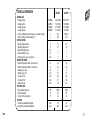
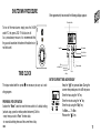
Users
Manual
A/23 MFFI
A/27 MFFI
TABLE OF CONTENTS
1) GENERAL INFORMATION
2) OPERATING INSTRUCTIONS
3) TIME CLOCK
4) USEFUL INFORMATION
AND TROUBLESHOOTING
page 5
page 8
page 11
page 13
IMPORTANT
Please read this manual carefully.
For additional information, please consult the “Installation and Servicing
Instructions.”
Please ensure manuals provided are kept with the appliance so that they
can be used by the end-user, installer or our authorised engineer.
B022
MTS (GB) Limited support the
, initiative. Your installer will give
you, and show you how to use, a logbook which will give you important
information about your boiler, and heating system. Please have this logbook to hand whenever you contact a service engineer or us.
All CORGI Registered Installers carry a CORGI ID card, and have a
registration number. Both should be recorded in your boiler Logbook.
You can check your installer is CORGI registered by calling CORGI
direct on :- (01256) 372300.
3
Dear Customer,
Thank you for choosing an ARISTON combination boiler.
We guarantee that your boiler is a reliable and technically sound
product.
This User’s Manual provides detailed instructions and recommendations for proper use.
Remember to keep this manual in a safe place for future
reference.
Your local MTS Servicing Centre is at your complete disposal for
all requirements.
MTS (GB) Limited
4
The guarantee on this appliances is valid for 12
months from the first day of installation.
Repairs to the electric, hydraulic or gas circuits
may be carried out only by your local authorised
MTS Servicing Centre.
Every attempt has been made to avoid errors of any kind
in this User’s Manual, the Management invites customers to inform
of any inaccuracies which they may find.
This will help to improve our service
B022
TECHNICAL INFORMATION
GENERAL DATA
Heating input max
Heating input min
Heating output max
Heating output min
Efficiency at Maximum Thermal Capacity (see installation manual)
Efficiency at Reduced Thermal Capacity (*)
CENTRAL HEATING
Operating Temperature max
Operating Temperature min
Maximum Heating Pressure
Minimum Heating Pressure
Built-in expansion vessel - Total capacity
DOMESTIC HOT WATER
Maximum Temperature of Water for Domestic Use
Minimum Temperature of Water for Domestic Use
Working pressure max
Working pressure min
Flow rate ∆T 25°C
Flow rate ∆T 35°C
Minimum flow rate
ELECTRICAL DATA
Electrical Supply/ Frequency
Power Consumption
Protection of Electrical System
CATEGORY
Nominal Pressure/Methane Gas (G20)
Nominal Pressure/Liquid Gas (G30-G31)
B022
A/23 MFFI
A/27 MFFI
kW(Btu/h)
kW(Btu/h)
kW(Btu/h)
kW(Btu/h)
%
%
25.6 (87364)
11.0 (37539)
23.1 (78491)
9.2 (31396)
90.2
87.8
29.8 (101707)
12.0 (40956)
27.3 (92492)
10.1 (34471)
90.6/91.6
88.3
°C
°C
bar
bar
litres
82
42
3
1
7
82
42
3
1
7
°C
°C
bar
bar
l/min
l/min
l/min
56
36
6
0.2
12.8
9.1
2.6
56
36
6
0.2
14.8
10.6
2.6
V/Hz
W
IP
230/50
150
44
230/50
190
44
mbar
mbar
20
30-37
20
30-37
5
MODELS A/23 - A/27 MFFI
40° 50° 60° 70° 80°
°C
6
°C
LEGEND
A)
B)
C)
D)
E)
F)
G)
H)
I)
L)
O)
Ignition Lockout Reset Button/Safety (Overheat)Thermostat Reset
Ignition Lockout L.E.D.
Selector Knob for Summer/Winter/Flue Analysis Modes
Low System Water Level L.E.D.
Temperature Adjustment Knob for Domestic Hot Water
Heating System Thermometer
Safety (Overheat)Thermostat Intervention L.E.D.
Adjustment Knob for Heating Temperature
On/Off L.E.D.
On/Off Switch
Heating System Pressure Gauge
B022
OPERATING INSTRUCTIONS
CAUTION
-
Installation, start-up, adjustments and maintenance must be performed by a competent person only in accordance with the Gas Safety
(Installation & Use) Regulations (1984) and the instructions provided.
Improper installation may cause damage or injury to individuals, animals and personal property, for which the manufacturer will not be
held liable.
To ensure efficient and safe operation it is recommended that the boiler is serviced annually by a competent person.
If it is known or suspected that a fault exits on the appliance, it must
not be used until fault has been corrected by a competent person
-
HELPFUL SUGGESTIONS
O
To get the most out of your boiler, we have provided you
with some useful advice on the proper use and maintenance:
- Periodically check the system pressure using the pressure gauge “O”, make sure that the pressure is between 1.0 and 1.5 bar
(the blue part on the gauge) when the system is off and cool.
The warning L.E.D. “D” will indicate if the pressure is below the minimum
B022
-
recommended value. Consult your installer for checking and refilling the
system.
The outer panels of the unit's case must only be cleaned with a damp
cloth. Do not use abrasive cleaners. The Control panel can be wiped with
a damp or dry cloth. Spray polishes must not be used on the control panel
surface or knobs. Care must be taken in preventing any liquid entering the
appliance.
If the water is exceptionally hard, install a water softener so that the efficiency of the unit remains the same over time, as this will consume less gas.
To improve comfort and take full advantage of the heat produced by the
boiler, it is recommended that an external thermostat be installed.
If the boiler is not going to be used for an extended
I
period of time, turn off the supply of electricity to the
unit by pressing the On/Off switch “L”.
The green L.E.D. “I” will turn off. Then turn off the
L
supply of gas to the unit itself.
It is good practice to clean and service the appliance
and central heating system every year.
Call an Authorised Service Centre.
7
START-UP PROCEDURE
LIGHTING
I
L
Before starting the unit, check the following:
- The water pressure on the pressure gauge “O”;
- That the gas cock and the inlet for domestic water are
open.
These models are equipped with electronic ignition which utilises contact
ionisation.
To make the boiler operational, simply press the On/Off switch “L”.
The green L.E.D. “I” will then turn on.
At this point the boiler is ready for use, a centralised
electronic control unit will automatically light the main
burner when needed. If the burner does not light within B
the pre-set safety time limit, the red “B” L.E.D. will light
up. To reset the ignition system, the reset button “A”
must be pressed. Should the system fail to light a
second time, check to make sure that the gas cock is
open. If the problem persists, contact one of our
Authorised Service Centres for assistance.
8
WINTER AND SUMMER OPERATING MODES
The boiler is fitted with a selector knob “C” which
C
allows you to switch between winter <
> and
summer <
> operating modes and vice versa.
When the knob is set to <
>, the boiler can
serve the dual purpose of providing heat and/or hot
water for domestic use.
The supply of hot water for domestic use always
takes precedence over heating. When the knob is
set to <
>, the boiler cuts out the heating system and only provides hot
water for domestic use (when needed).
A
B022
TURNING ON THE BOILER
Installation without a room thermostat :
- Turn on the power supply to the boiler by pressing the
On/Off switch “L”; the green L.E.D. “I” will the turn on;
- Turn the “C” selector knob to <
I
L
>;
- Regulate the temperature of the water in the boiler by
turning the “H” knob. The temperature can vary
between 42°C and about 82°C;
- Check the boiler temperature on the thermometer with
the yellow L.E.D.s “F”. With this type of installation, the
ambient temperature does not influence the operation
of the boiler and
the circulation
40° 50° 60° 70° 80°
pump always remains in
F
operation.
B022
Installation with a room thermostat:
H °C
- Turn the “C” selector knob to <
>;
- Turn on the power supply to the boiler by pressing the
On/Off switch ”L”; the green L.E.D. will then turn on;
- Turn the thermostat knob “H” to the highest temperature setting.
- With this type of installation, the boiler is controlled by a room thermostat.
Therefore, it runs until the ambient temperature has reached the temperature setting on the thermostat. At that point, the main burner will turn off
and the circulation pump will stop.
C
TURNING OFF THE BOILER
I
H
°C
Installation without a room thermostat:
To turn off the heating, turn the “C” selector knob to
<
>. The boiler will still provide hot water for domestic
use.
L
9
ADJUSTING THE HEATING TEMPERATURE
To economise on consumption while achieving the highest level of comfort,
the temperature adjustment knob is designed with three different heating
zones based on the temperature outside the home.
Rotate the knob “H” as shown below.
From + 5°C
to - 5°C
H
°C
From + 5°C
to + 15°C
°C
°C
Lower
to - 5°C
PRODUCTION OF HOT WATER
FOR DOMESTIC USE
E
ADJUSTING THE TEMPERATURE OF
WATER FOR DOMESTIC USE
E
It is recommended that the temperature for the hot water
should not be set to high temperatures and then mixed
with cold water. Setting the thermostat to a medium temperature is preferable (see figure).
10
°C
- Turn on the power to the boiler by pressing the
On/Off switch “L”;
- With these settings, the boiler is already ready for use,
regardless of the position of the “C” selector knob.
- Turn the "E" knob to select the temperature for the hot water (between
36°C and about 56°C depending on the flow rate of the water).
°C
B022
SHUTDOWN PROCEDURE
After approximately two seconds the following display appears:
Weekdays blinks
To turn off the main burner, simply press the On/Off
switch “L”; the green L.E.D. “I” will also turn off.
As a precautionary measure, it is recommended that
the gas cock located on the bottom of the boiler be turned off as well.
I
L
Input time
Enter minutes
Enter the hour
Manual switch
Enter
switching time
TIME CLOCK
The steps marked with the symbol are necessary to carry out a switching program.
PREPARING FOR OPERATION
Activate the “Reset” switch to reset the time switch to it’s default setting
(activate using a pencil or similar pointed instrument). Do this:
- every time you wish to “Reset” the time clock;
- to erase all switching times and the current time of day.
B022
Enter weekdays
Summer and
winter time
setting
Reset
ENTER CURRENT TIME AND WEEKDAY
Keep the “
” key pressed down. During the
summer time period press the +/-1h key once.
Enter the hour using the “h” key.
Enter the minutes using the “m” key.
Enter the day using the “Day” key.
1 = Mon ....... 7 = Sun
Release the “
” key.
11
The colon now blinks once a second.
AM/PM TIME DISPLAY
If you press the “+/-h” and “h” keys as the same time, the time display switches into the AM/PM mode.
Notes: If you keep the “h” and “m” keys pressed down for more than 2
seconds, the display will enter fast forward scroll mode.
ENTERING THE SWITCHING TIMES
If your entry is incomplete, the segments not yet
selected will blink in the display.
You have 20 memory locations available. Each switching time takes up one memory location.
Keep pressing the “Prog” key until a free memory
location is shown in the display “-- : --”.
Program ON or OFF with the “
” key:
“
” = ON - “
” = OFF.
Enter the hour using “h”; enter the minutes using “m”.
If a switching command is to be carried out every day (1 2 3 4 5 6 7) then
store using the “
” key, otherwise select the days it is to be carried out
on by using the “Day” key.
When the day selection is left blank, the programmed switching instruction
12
operates at the same time every day.
1234567
Monday ..... Sunday
123456
Monday ..... Saturday
12345
Monday ..... Friday
1234567
Saturday ..... Sunday
1
Monday
.....
(selection of single days)
7
Sunday
” key or push “Prog” key if you are going to continue
Store using the “
programming. The time switch enters the automatic operating mode and
displays the current time of day. Begin any further entry of a switching time
with the “Prog” key.
If necessary, once you have finished programming, and have returned to
the current time display, by pressing the “ ” button, the timer will not automatically switch to the current programmed status until the next timed setting. You can put the timer into the correct mode with the “
” key.
B022
ADDITIONAL FUNCTIONS
READING THE PROGRAMMED SWITCHING TIMES
Pressing the “Prog” key displays the programmed switching times until the
first free memory location appears in the display “ -- : --”.
Switching from summer time to winter and vice versa.
Press the “+/-1h” key once.
MANUAL OVERRIDE KEY
With the “
” you can change the current switching settings at any time.
The switching program already entered is not altered.
Automatic
Operation
Manual
Operation
= ON
= OFF
= ON
= OFF
= ON
= OFF
The switching times correspond to the program
entered.
B022
Continuous
Operation
[ ]
If the current switching
mode is changed manually, the next switching time
will be carried out automatically again according
to the entered switching
program.
You can only return to
automatic mode from
the continuously ON and
continously OFF switching modes by pressing
” key.
the “
If you now press the “Prog” key once again, the number of free memory
locations will be displayed, e.g. “Fr 20”. If all memory locations are occupied, the display “Fr 00” appears.
CHANGING THE PROGRAMMED SWITCHING TIMES
Press the “Prog” key repeatedly until the switching time you want to change is displayed. You can now enter the new data. See “Entering the switching times”.
13
Notes on storing switching times:
If you end your entry of the switching times by pressing the “Prog” key, the
switching time you have entered will be stored and the next memory location displayed. Entry of further switching times is also carried out as described in “Entering the switching times”.
In addition, a complete switching command is stored automatically after
around 90 seconds provided no other key is pressed.
The time switch then enters the automatic operating mode and displays the
current time again.
DELETING INDIVIDUAL SWITCHING TIMES
Press the “Prog” key repeatedly until the switching time you wish to delete is shown in the display.
” key pressed
Then set to “--” using the “h” or “m” key and keep the “
down for around 3 seconds.
The switching time is now erased and the current time is displayed.
TECHNICAL DATA
Ambient temperature:
Running reserve:
Memory locations:
Shortest switching time:
Programmable:
14
- 10°C to + 55°C
5 h (not for 1.5 V DC)
20
1 minute
Every minute
USEFUL INFORMATION AND
TROUBLESHOOTING
BOILER SHUTDOWN
The boiler unit is equipped with safety devices which intervene in certain
situations to shutdown the boiler.
Some of these situations are signalled by the unit and can be corrected by
the user.
SHUTDOWN DUE TO THE FAILURE OF THE
BURNER TO LIGHT AUTOMATICALLY
This anomaly is indicated by the red “B” L.E.D.
To reset the unit, press and then release the “A” button.
At this point, the electronic ignition system will attempt
to light the burner again.
Repeat this procedure as needed. If lighting failure
occurs repeatedly, it is recommended that you contact
one of our Authorised Service Centres.
B
A
B022
SHUTDOWN DUE TO OVERHEATING
This anomaly is signalled by the red “G” L.E.D.
The boiler shuts off because the safety thermostat
detected that the boiler temperature has reached
the temperature limit.
To reset the unit, wait until the boiler has cooled
and then press the “A” button.
If the safety thermostat shuts off the unit on a frequent basis, contact one of our Authorised Service
Centres for assistance.
B022
NOTES
G
A
15
GROUP
Manufacturer:
Merloni TermoSanitari SpA - Italy
Commercial subsidiary:
MTS (GB) LIMITED
MTS Building
Hughenden Avenue
High Wycombe
Bucks HP13 5FT
Telephone: (01494) 755600
Fax: (01494) 459775
Internet: http://www.mtsgb.ltd.uk
E-mail: [email protected]
Technical Service Hot Line: (01494) 539579
Cod. 23 99 84 1257 311 / B022 -
bieffe
Recanati