1
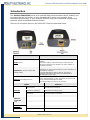
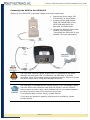
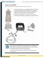
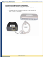
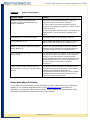
PS6U1UPE USB-Peripheral to Ethernet Adapter Mobility Electronics, Inc 9918 Via Pasar, San Diego, CA 92126, USA Phone: (858) 880-2225 Fax: (858) 530-2733 www.invisioncradles.com User Guide InVision USB-Peripheral to Ethernet Adapter User Guide Copyright© 2005 Mobility Electronics, Inc. All rights reserved. The information in this document is subject to change without notice. Disclaimer Mobility Electronics, Inc. assumes no responsibility for any damage or loss resulting from the use of this user guide. Mobility Electronics, Inc. assumes no responsibility for any loss or claims by third parties that may arise through the use of this product. Mobility Electronics, Inc. assumes no responsibility for any damage or loss caused by deletion of data as a result of malfunction, dead battery, or repairs. Be sure to make backup copies of all important data on other media to protect against data loss. First Edition — December 2005 Rev: A Trademarks Symbol is a registered trademark of Symbol, Inc. Microsoft, Windows, Window CE, ActiveSync, and Windows Mobile are either registered trademarks or trademarks of Microsoft Corporation in the United States and/or other countries. All other registered trademarks, trademarks, service marks, and/or logos are the property of their respective companies. Mobility Electronics, Inc ii InVision USB-Peripheral to Ethernet Adapter User Guide Contents CONTENTS .......................................................................................... III INTRODUCTION ..................................................................................... 1 GETTING STARTED ................................................................................. 2 Before You Begin ....................................................................................... 2 Connecting to the PS6U1UPE ....................................................................... 2 Setting up the MC50 ............................................................................... 2 Installing the MC50 Software Drivers .................................................................. 2 Connecting the MC50 to the PS6U1UPE ............................................................... 5 Setting up the MC3000 ............................................................................ 6 Connecting the PS6U1UPE to your Network ................................................... 7 PRODUCT/TECHNICAL SUPPORT ............................................................... 8 Product Registration................................................................................ 8 Troubleshooting...................................................................................... 8 Other ActiveSync Problems ...................................................................... 9 APPENDIX A – REGULATORY INFORMATION ............................................... 10 Radio Frequency Interference Requirement .............................................. 10 FCC Statement .............................................................................................. 10 Radio Frequency Interference Requirement - Canada .......................................... 10 APPENDIX B – WARRANTY .................................................................... 11 Mobility Electronics, Inc iii InVision USB-Peripheral to Ethernet Adapter User Guide Introduction The InVision PS6U1UPE serves as an essential data communications device, enabling you to synchronize the information on your Symbol® MC50 and a host computer using ActiveSync® technology, or your Symbol® MC3000 using your customized synchronizing software, across a standard Ethernet network. There are 3 connection ports on the PS6U1UPE. These are described below: Ports Function 5VDC (Power) A standard barrel port used for connecting the Power Adapter. This power adapter (PN 170140-000) is required for the MC50 and optional for the MC3000. The power adapter is available separately. USB Mini-B (use with custom USB Adapter Cable) Used to connect to the MC50 or MC3000 USB ports for ActiveSync, or other communications, to other computers on the Ethernet networks. A special USB adapter cable is required. The cable is available separately for the MC50 (PN 190087-000) or MC3000 (PN 170373-000). Ethernet (RJ45 Ethernet Port) Used to connect to your Ethernet network for ActiveSync, or other communications, to other computers on the networks, using a standard RJ45 Ethernet cable The standard Ethernet cable is not provided. Lights USB LED Ethernet Green LED (left) Ethernet Yellow LED (right) Function Off (MC3000) No USB Host connectivity Solid Green (MC3000) USB Host connectivity/power Off (MC50) USB Host Mode not-enabled Solid Green (MC50) USB Host Mode enabled Solid Green Link established Flashing Green Link activity Off No link established Off 10 Mb connection Solid Yellow 100 Mb connection Mobility Electronics, Inc 1 InVision USB-Peripheral to Ethernet Adapter User Guide Getting Started Before You Begin Before you can successfully connect your Symbol MC50 or MC3000 to your network with your PS6U1UPE, you must have successfully configured your device for ActiveSync operations. For assistance with ActiveSync operations, please refer to your Symbol Integrator Guide. Only after you have successfully created an ActiveSync partnership between your MC50 or your MC3000 and your host computer, and completed an ActiveSync operation, should you attempt to connect your device to your network. This is important even if you plan to use other 3rd Party synchronization software, because using ActiveSync allows you to validate your software/hardware installation. Then, if you have problems later making your 3rd Party software work, you can focus on the 3rd Party software configuration because you know everything else works fine. Connecting to the PS6U1UPE Setting up the MC50 Installing the MC50 Software Drivers The MC50 requires the installation of software drivers to enable it to communicate through your network to complete ActiveSync, or synchronization operations. By design, the MC50 functions as a USB client device. With the installation of these drivers, the MC50 will now be able to also function as a USB host device. If you have not already done so, go to www.invisioncradles.com and download the latest PS6U1UPE drivers. The drivers are provided in a self-extracting ZIP file. Simply download the file to your computer and follow these simple steps: Step 1 – Unpack the software Double-click the downloaded file to extract the drivers. The ZIP file will automatically unpack the MC50 driver software components to a default directory called C:\MC50Drivers. You may change this directory if you wish. However, if you change the directory be sure that you remember where you put it, because this is the location where you will move the files “from.” Step 2 – Verify MC50 Configuration Before you start to install the MC50 driver software, you must ensure you have successfully completed an ActiveSync between the MC50 and your computer via the MC50’s USB cable. If you have not already configured ActiveSync, please do so now and ensure that you successfully synchronize between the MC50 and your PC before you continue. If you need help, refer to your MC50 Integrator’s Guide, or contact Symbol Technical Support for assistance. Mobility Electronics, Inc 2 InVision USB-Peripheral to Ethernet Adapter User Guide Step 3 – CAB File Installation To install the CAB file directly onto the MC50, follow these simple steps: Connect the MC50 USB cable to a USB port on your computer. Open your Windows Explorer and browse to the \MC50 Drivers folder to locate the file USBOTG.MC50.CAB. Next, open ActiveSync and click on the Explore button. Then “drag & drop” the USBOTG.MC50.CAB file onto the My Pocket PC icon in the ActiveSync window. You will be prompted that the file may need conversion. Simply click OK to continue. Step 4 – Install the CAB File Use the MC50’s stylus to open Start>>Programs>>File Explorer. You should find the USBOTG.MC50.CAB file below the bottom of the folder list. Use the stylus to double-click on the USBOTG.MC50.CAB file and execute it After the CAB file installation completes, you will need to use the stylus to perform a soft reset the MC50. The reset button can be found on the bottom of the MC50. Consult your MC50 documentation if you need help finding the reset button. Step 5 – Install the Additional Drivers After the MC50 has reset, return to your computer’s ActiveSync Window and doubleclick on the My Pocket PC icon to display the main folder structure on the MC50. When you see the adjacent file structure, double-click on the \Windows folder to gain access to the bvd_udc_ser.dll file which must be replaced by a custom version of the USB function driver. This new driver is included in the MC50 Drivers folder. To correctly replace the file, browse to the MC50 \Windows folder with the ActiveSync File Explorer and rename the bvd_udc_ser.dll file to bvd_udc_ser_old.dll. Mobility Electronics, Inc 3 InVision USB-Peripheral to Ethernet Adapter User Guide Next, click on the Windows Explorer and select the four files shown in the adjacent window – (1) USBMode.cpl, (2) USBMode.exe, (3) bvd_udc_ser.dll, and (4) USBPSMDM.dll. To select all four files at one time, press the CTRL key as you “left-click” on each file’s name. When finished, all four files will be highlighted. Now, drag & drop all four of the files to the \Windows folder on the MC50. The bvd_udc_ser.dll file should automatically overwrite the older file. If prompted to overwrite the existing file, select “YES” and continue. If you have problems getting the new version to replace the old version, then and try it again. After you have successfully copied all four files to \Windows, the MC50 must be reset (soft reset). Step 6 – Configure the USB Mode To use the USB client modem on the MC50, go to Start>>Settings>>System>>USB Mode. Select "Enable Host mode only" Check "Load modem driver at startup" Check "Set Host mode on port open" Tap OK in the upper right corner of the MC50 display screen Step 7 – Finishing Up Place the MC50 into its cradle and connect the MC50 USB cable to the PS6U1UPE device with the USB Adapter Cable as described in the next section. From this point on, Host mode will be enabled whenever COM9 is opened. Mobility Electronics, Inc 4 InVision USB-Peripheral to Ethernet Adapter User Guide Connecting the MC50 to the PS6U1UPE Setting up your PS6U1UPE is easy and includes only these simple steps. 1. Connect the Power Supply (PN 170140-000), as shown below. 2. Connect the Mini USB Adapter Cable (PN 190087-000) to the MC50 USB cable and to the PS6U1UPE, as shown below. 3. Connect the Ethernet Cable to the network (see the Section “Connecting the PS6U1UPE to your Network” for more information.) The PS6U1UPE requires a power supply when it is connected to the MC50. Although the solid green LED is lit whenever the USB cable is correctly connected, there is not enough power to operate the device. Failure to connect the power supply before using could damage the device. The PS6U1UPE is provided without a power supply or any USB adapter cables. Since the MC50 uses a different cable than the MC3000, and the MC3000 doesn’t require a power supply, each peripheral device is provided separately to ensure you don’t have to buy items you cannot use. To purchase a cable or power supply, contact Mobility. If you have any questions regarding requirements or availability, please contact Mobility. Mobility Electronics, Inc 5 InVision USB-Peripheral to Ethernet Adapter User Guide Setting up the MC3000 Setting up your PS6U1UPE is easy and includes only these simple steps. 1. Connect the USB Mini-A to Mini-B Adapter Cable (PN 170373-000) to the MC3000 cradle and to the PS6U1UPE, as shown below. 2. Connect the Power Supply (PN 170140-000), if you have one, as shown below. The power supply is not required because the PS6U1UPE can draw power directly from the MC3000. 3. Connect the Ethernet Cable to the network (see the Section “Connecting the PS6U1UPE to your Network” for more information) The PS6U1UPE is provided without a power supply or any USB adapter cables. Since the MC50 uses a different cable than the MC3000, and the MC3000 doesn’t require a power supply, each peripheral device is provided separately to ensure you don’t have to buy items you cannot use. To purchase a cable or power supply, contact Mobility. If you have any questions regarding requirements or availability, please contact Mobility. Mobility Electronics, Inc 6 InVision USB-Peripheral to Ethernet Adapter User Guide Connecting the PS6U1UPE to your Network Completing the setup of the PS6U1UPE to your network is simple: 1. Connect one end of a standard RJ45 Ethernet cable to the PS6U1UPE, as shown below. 2. Connect the other end of the cable to an open port on your network’s hub, switch, or router, as shown below. Mobility Electronics, Inc 7 InVision USB-Peripheral to Ethernet Adapter User Guide Product/Technical Support Mobility is committed to providing its customers with first-class customer service and technical support. For your convenience, a few troubleshooting techniques are provided below that might help you fix your problem quickly and easily. If you have a different issue, or if you have tried these and they didn’t resolve your problem, please feel free to contact Technical Support at: Mobility Electronics 9918 Via Pasar San Diego, CA 92126 Phone (858) 880-2225 Fax: (858) 530-2733 E-mail: Web: [email protected] www.invisioncradles.com If you use the website, please select the Cradles & Adapters menu option from the Support menu. Product Registration A product registration card is included with your PS6U1UPE product. Please fill out the registration card and drop it in the mail so that we will know who you are if you ever need to call. While registration is not required to resolve warranty claims, it will help make any warranty claim easier to complete. For your convenience, you may also register online at: www.invisioncradles.com Troubleshooting Symptom: Nothing Works! Possible Cause Action Poor cable connections Check the cables to ensure you have them connected correctly and securely. For more information, see the earlier sections on how to connect the cables. Faulty or defective cables When properly connected and in good working order, the lights on the adapter ends will be lit. Low power (MC50) The MC50 requires a power adapter (PN 170140-000) to work correctly. A solid green light on the USB end of the adapter does NOT mean that there is enough power to make it work with an MC50. The light is an indicator that the cable is connected correctly and the MC50 has been configured for “host mode” operations. Mobility Electronics, Inc 8 InVision USB-Peripheral to Ethernet Adapter User Guide Symptom: It won’t ActiveSync! Possible Cause Action ActiveSync partnership between host computer and your MC50/MC3000 is not correctly established Reconnect the MC50/MC3000 directly to the host computer and try an ActiveSync operation. If it fails, refer to the Symbol Integrator Guide for guidance with ActiveSync problems, or contact Symbol Technical Support. If ActiveSync works OK when directly connected to the host computer, see the remaining “possible cause” items. MC50/MC3000 not configured for DHCP Reconfigure device to accept DHCP IP address Cannot find DHCP server Ensure PS6U1UPE adapter is connected to a router, switch, or hub that is serviced by a DHCP server. Missing, or improperly configured, software drivers (MC50 only) Reset (hard reset) the MC50 as directed in Symbol Integrator Guide. Reinstall and reconfigure software drivers in accordance with current instructions. Won’t automatically ActiveSync when inserted into the cradle The autodetect/autostart capability of ActiveSync does not function whenever your device is not connected directly to your host computer via the USB cable. Synchronization operations must be initiated from the MC50/MC3000 device. They cannot be started from the host computer unless there is a “direct connection.” Custom synchronization software does not have the ability to “launch” a synchronization function The MC3000 uses the Windows CE operating system which does not include an ActiveSync launch button. Therefore, the MC3000 cannot initiate a synchronization operation unless the synchronization software contains a feature that allows the user to initiate the synchronization action. Other ActiveSync Problems If you require more information on the ActiveSync process, please refer to the ActiveSync chapter in your Symbol Integrator Guide or visit www.Microsoft.com and search for ActiveSync. For help with other technical issues, contact Mobility Technical Support using the contact information provided at the start of this chapter. Mobility Electronics, Inc 9 InVision USB-Peripheral to Ethernet Adapter User Guide Appendix A – Regulatory Information Radio Frequency Interference Requirement FCC Statement This equipment has been tested and found to comply with the limits for a Class B digital device, pursuant to Part 15 of the FCC Rules. These limits are designed to provide reasonable protection against harmful interference in a residential installation. This equipment generates, uses, and can radiate radio frequency energy and, if not installed and used in accordance with the instructions, may cause harmful interference to radio communications. However, there is no guarantee that interference will not occur in a particular installation. If this equipment does cause harmful interference to radio or television reception, which can be determined by turning the equipment off and on, the user is encouraged to try to correct the interference by one or more of the following measures: • Reorient or relocate the receiving antenna • Increase the separation between the equipment and receiver • Connect the equipment into an outlet on a circuit different from that to which the receiver is connected • Consult the dealer or an experienced radio or television technician for help. Changes or modifications not expressly approved by Mobility Electronics could void the user’s authority to operate the product. Radio Frequency Interference Requirement - Canada This Class B digital apparatus complies with Canadian ICES-003. Cet appareil numérique de la classe B est conforme à la norme NMB-003 du Canada. Mobility Electronics, Inc 10 InVision USB-Peripheral to Ethernet Adapter User Guide Appendix B – Warranty Mobility Electronics, Inc. warrants this product against defects in materials and workmanship to the original purchaser (or the first purchaser in the case of the remanufactured product being sold) for a period of one (1) year from the date of shipment. This warranty is limited to a repair or replacement of the product. To obtain warranty service, the purchaser must first call Mobility Electronics, Inc. for an RMA number, then return the product to Mobility Electronics, Inc. for repair or replacement. Purchaser shall prepay shipping charges for products returned to Mobility Electronics, Inc. Mobility Electronics, Inc. will pay for return of the products to purchaser, except that purchaser shall pay all shipping charges, duties, and taxes for products returned to Mobility Electronics, Inc. from a country other than the United States. Mobility Electronics, Inc. makes no other warranty of any kind with regard to this material. Mobility Electronics, Inc. shall not be liable for errors contained herein or for incidental or consequential damages in connection with the furnishing, performance, or use of this material. Within thirty (30) days of receipt should the product fail for any reason other than damage due to customer negligence; purchaser has the right to return the product for a full refund of the purchase price. If the purchaser wishes to upgrade or convert to another Mobility Electronics, Inc. product within the thirty (30) day period, purchaser has the right to return the product and apply the full purchase price toward the purchase of the other product. Any other return will be subject to Mobility Electronics, Inc.’s existing restocking policy. MOBILITY ELECTRONICS, INC. WARRANTS THAT THIS PRODUCT IS NEW OR HAS BEEN REMANUFACTURED TO MEET NEW STANDARDS USING NEW OR SERVICEABLE USED PARTS. MOBILITY, INC. MAKES NO OTHER WARRANTY, EITHER EXPRESSED OR IMPLIED, WITH RESPECT TO THIS PRODUCT. MOBILITY, INC. SPECIFICALLY DISCLAIMS THE IMPLIED WARRANTIES OF MERCHANTABILITY AND FITNESS FOR A PARTICULAR PURPOSE. Some states or provinces do not allow limitations on how long an implied warranty lasts, so the above limitation or exclusion may not apply to you. THE REMEDIES PROVIDED HEREIN ARE CUSTOMER’S SOLE AND EXCLUSIVE REMEDIES. IN NO EVENT SHALL MOBILITY, INC. BE LIABLE FOR ANY LOST PROFITS, DIRECT, INDIRECT, SPECIAL, INCIDENTAL, OR CONSEQUENTIAL DAMAGES, WHETHER BASED ON CONTRACT, TORT, OR ANY OTHER LEGAL THEORY. Mobility Electronics, Inc 11 InVision USB-Peripheral to Ethernet Adapter User Guide Mobility Electronics, Inc 12 InVision USB-Peripheral to Ethernet Adapter User Guide Mobility California, Inc. 9918 Via Pasar, San Diego, CA 92126, USA Phone (858) 880-2225 • Fax (858) 530-2733 Email: [email protected] • www.invisioncradles.com Part Number 190086-000 Rev A Mobility Electronics, Inc 13