1
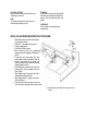
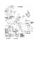
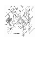
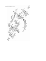
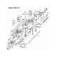
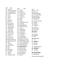
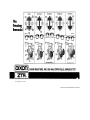
IMPORTANT
The Dixon ZTR mower is both easy and fun to
operate. However, any power mower must be
operated properly to be safe. It is not a toy or a
recreational vehicle. Before you start to use the
mower, read the operator's manual carefully, and
become completely familiar with the controls.
Your Dixon dealer will gladly provide a checkout ride, and answer any questions.
READ CAREFULLY
You have purchased a top quality lawn mower that
has been carefully inspected and adjusted at the
factory. This lawn mower is warranted for 1 year from
date of delivery against all defects in materials and
workmanship. Lawn mowers used for commercial
service are warranted for 30 days from date of delivery.
SEE YOUR DEALER FOR WARRANTY SERVICE OR
PARTS.
ONE-YEAR LIMITED WARRANTY
This lawn mower is warranted for one (1) year from date of delivery against all defects in materials and workmanship. Lawn
mowers used for commercial service are warranted for 30 days from date of delivery. (Lawn mowers other than those used
only at residence of owner are considered as commercial service.)
Each new mower is warranted against manufacturing defects in material and workmanship under normal use and service.
Our obligation, under this warranty, shall be limited to the replacement to the original retail purchaser of any part or parts,
which, within the warranty period, shall be shown to be defective due to faulty workmanship or materials at the factory. All
parts claimed defective must be returned to the factory for inspection, repa ir, or replacement with transportation charges
prepaid.
This warranty does not apply to damage in transit or damage caused by misuse, negligence or accident, to alterations or
repairs done outside the factory or authorized service stations, nor does it obligate us to assume any transportation charges
in connection with the replacement of parts claimed to be defective.
Our warranty does not apply to the blades, adapters, chains or belts on our mowers due to the very nature of the function
they perform and to the elements they are exposed to.
The warranty specifically excludes engines, tires, and batteries which are warranted separately by their respective
manufacturers. All claims for defective engines or engine parts must be made in accordance with the engine manufacturer's
warranty.
We reserve the right to make changes in design and changes or improvements on our product without imposing any
obligation upon ourselves to install the same on products heretofore manufactured.
This warranty is null and void if any parts .other than original manufacturer's parts are used. There is no other express
warranty.
IMPLIED WARRANTIES, including those of merchantability and fitness for a particular purpose, are limited to one (1) year
from purchase-and, to the extent permitted by law, any and all implied warranties are excluded.
SERIAL NUMBERS
The lawn mower has three serial numbers:
Mower Number — Located on frame at right rear transaxle mount. Transaxle Number — Located on transaxle.
Engine Number — Located on engine. When referring to serial number on Warranty Registration, etc., use Mower
Serial Number located on frame.
SAFETY INSTRUCTIONS
BEFORE MOWING
1. Read these safety instructions and
engine manufacturer's operating and
maintenance instructions that are
furnished with the mower.
2. Discuss proper maintenance with your
Dixon dealer, to save money and prevent
injury. Consult your dealer before
removing any parts.
3..Don't allow anyone to operate your
Dixon mower without proper instruction.
Young children should never be allowed
to operate any power mower, riding or
walking.
4. Before mowing, pick up all debris —
particulary stones and sharp objects.
5. Before starting the engine, make sure
the gas cap is in place.
DURING MOWER OPERATION
1. The revolutionary Dixon mower attracts
many admiring neighbors. But when
mowing, all persons — especially
children — and pets should be cleared
from the mowing area.
2. Wear appropriate, safe clothing when
mowing — close-fitting jeans or slacks
and heavy leather or safety shoes with
rough soles. Never use any kind of
mower with bare feet or open sandals,
not even an old push-type model!
3. When grass is wet or slippery, do not use
any riding mower.
4. Always mow at the slowest speed that
will cut satjsfactorily.
5. Keep hands and feet away from the
blade at afl times.
6. Although the Dixon mower is equipped
with a missile
deflector which directs downwards all blade propelled objects, keep persons clear of the
discharge chute. Do not operate mower unless
deflector is in place.
7. Use extreme caution when mowing hills or
slopes with any mower.
8. Always disengage blades before taking the
mower across walks or objects that project
above the surface.
9. When the mower is not in use, turn the engine
off; never leave the engine running unattended.
Your Dixon mower is equipped with a weightsensitive switch that kills the en gine when
operator leaves the seat while blades are
engaged. Test this important safety feature
before each time mower is used. This may be
done by starting engine, engaging blades and
then rising slightly from seat. If engine does not
stop, see your dealer for necessary repair.
10. Before adjusting your mower or adding fuel,
turn the engine off. Let it cool, and disconnect
the spark plug so the engine cannot start by
accident. Be sure all moving parts are stopped.
11. Never run the engine indoors; the fumes are
dangerous.
12. Before backing your Dixon mower, stop, turn
around, and look.
13. Gasoline fumes are explosive; use only
approved gasoline containers to store small
amount of fuel. No special oil/gas mixtures are
needed for your Dixon mower.
14. If the mower should start vibrating, stop the
engine immediately and check for damage or
loose parts. Vibration is usually the warning of
trouble.
15. Never lift lawn mower by the body; lift only by
the frame.
16. Never carry passengers.
ALWAYS SET PARKING BRAKE AND DISENGAGE BLADE OPERATION BEFORE DISMOUNTING.
IMPORTANT OPERATING
INSTRUCTIONS
Dixon ZTR mowers offer a new concept in mowing,
providing unique maneuverability and ease. The
following procedures will allow one to become
familiar with the unique method of control very
easily.
1. SET PARKING BRAKE — Be sure that drive
levers are free and in the neutral position.
(When drive levers are released, they should
return to neutral position.)
2. "Blade Operation" lever is to be set in the
"Disengage" position.
3. Move throttle control to "Choke" position.
4. To start models with electric starting, simply
insert ignition key and turn to the far right
position. When the engine starts, release the
ignition key and it will remain in the "RUN"
position. To stop the engine simply turn the key
to the "OFF" position.
NOTE: Some electric start models are also
equipped with manual start provision.
To start engine manually turn switch to
"RUN" and pull the starter rope.
5. Set engine to desired speed by adjusting
throttle control. (Suggest set at slow speed
during initial operation.)
6. NOTE SAFETY FEATURE: Safety switches
stop engine when operator leaves seat while
blades are engaged, and engine cannot be
started when blades are engaged. OPERATOR
SHOULD TAKE PRECAUTIONS AND NOT
RELY ON SAFETY SWITCHES.
7. This unit is equipped with a unique transaxle that
requires only two drive levers to control braking,
turning, direction and acceleration. TO GO
FORWARD
From neutral position gently push both drive
levers forward; to increase speed move levers
further forward.
TO GO BACKWARD
From neutral position gently pull both drive
levers
rearward.
TURNING
Turning is controlled by moving one drive lever
slightly forward or rearward of the other. To turn
left, move left lever rearward of right lever. To
turn "square corners" move lever of desired
direction to neutral. To turn on mower's own
axis (Zero Radius) reduce speed and move one
lever to reverse position and the other to forward
position.
BRAKING
To brake mower, move both levers in direction
opposite of travel, release levers to neutral, set
parking brake. When stopping on incline, it may
be necessary to hold slight pressure on levers
in direction opposite of slope, until parking
brake is set.
ALWAYS SET PARKING BRAKE BEFORE
DISMOUNTING.
INITIAL OPERATION
It is recommended that first operation of mower
be done at a slow throttle setting with mower
blades disengaged u ntil operator is thoroughly
familiar with the unit.
You may have a tendency to "over
control" mower at first. Slight movement
— fingertip control — is all that's
necessary for easy operation.
8. Mower Blade operation:
• Cutting height is set by positioning the
adjustment lever. Push button knob on top of
lever, set desired cutting height, lock in to
position by releasing button knob.
• To start mower blades, move lever on floor to
"engage" position. To stop mower blades,
move lever to "disengage" position.
ALWAYS DISENGAGE BLADE OPERATION
BEFORE DISMOUNTING.
9. Parking Brake:
Parking brake is on right hand side of floor area and is
engaged by pushing full forward with foot. To
disengage, pull lever back toward operator by hand. In
emergency situations, brake may be used in
conjunction with the natural braking of the transaxle by
applying pressure with foot. Always set parking brake
before dismounting. Be sure that parking brake is
disengaged before moving.
MAINTENANCE
BEFORE PERFORMING ANY MAINTENANCE,
SHUT OFF ENGINE, ALLOW TO COOL AND
DISCONNECT SPARK PLUG.
ENGINE
For complete engine operating and maintenance
information, refer to engine operating and maintenance
instructions furnished by the engine manufacturer and
supplied with each mower.
BATTERY
Procedure for initial activation of battery:
1. Fill with electrolyte solution to lower ring of battery.
2. Let stand for 30 minutes.
3. Charge at 4 amps for 3 hours or 1 amp for 12 hours.
4. After initial filling, fluid level may be maintained with
distilled water.
Procedure for off-season storage:
1. Charge battery.
2. Disconnect cables from battery terminals. Identify
cables so that they may be easily reconnected to -the
correct
terminal. (See also wiring diagram shown on
Body Assembly illustration.)
3. Clean top of battery and terminals.
4. Do not remove battery from mower.
5. To reactivate, reconnect cables to correct
terminals and charge battery if needed.
BELT ADJUSTMENT
The best tension for a V-belt drive is the lowest
tension at which the belts will not slip under
normal load condition. Check the tension on a
new belt frequently during first hours of operation
and every 10-15 hours or monthly thereafter.
Too much tension shortens belt and bearing life.
Too little tension causes slippage and loss of
power. Be sure that belts and pulleys are kept
free of foreign material. If belt slippage occurs,
tighten it just enough to prevent slippage.
TRANSAXLE DRIVE BELT
To adjust tension, loosen 4 bolts which hold
engine to mount and belt keeper in place.
Loosen tension bolt located at rear of machine.
Adjust tension bolt until desired tension is
achieved, tighten 4 bolts holding engine and
tighten tension bolt lock nut.
MOWER DRIVE BELT
Belt tension for mower drive belt is adjusted by
loosening nut on mower deck turnbuckle
assembly and turning turnbuckle to achieve
desired tension. Retighten nut. Tension should
be checked with belt in engaged position.
REPLACE BELTS WHEN ADJUSTMENT
CAN NO LONGER BE MADE
SATISFACTORILY OR IF BELTS BECOME
WORN.
BODY REMOVAL
A. ZTR-424 Body Removal
1. Disconnect throttle cable from engine.
2. Disconnect key switch wire loom from frame
wire loom at front of body.
3. Disconnect seat switch wire loom from frame
wire loom. This connection is located
approximately level with the back of the seat on
left hand side of frame under the body.
4. Remove four control lever bolts and remove
upper control levers.
5. Remove engaging handle by removing bolt and
nut
under handle. - 6. Disconnect brake pedal from
pedal arm by removing
the two bolts. 7. Remove two acorn nuts on front
floor and the two sheet
metal screws in transaxle body mount. Body will
lift
clear. To replace body reverse the above
procedure.
B. ZTR-422 Body Removal
1. Disconnect throttle cable from engine.
2. Disconnect two wire loom plugs, one going to
engine wires and one going to switch. Plugs are
located between back of transaxle mount and
battery.
OMIT STEP (3) AND FOLLOW ZTR-424 BODY
REMOVAL INSTRUCTIONS FROM STEP (4) ON.
REMEMBER TO REINSTALL SWITCH GROUND
WIRE ON LEFT REAR TRANSAXLE BODY
MOUNT SCREW.
CHAIN DRIVES
ADJUSTMENT
To adjust the drive chains, the body must be
removed and shims added behind the transaxle.
Loosen 4 bolts which hold the transaxle to the
frame. Insert shims as needed for adjustment
between transaxle and mount plates. When properly
adjusted, the slack span at the mid -point of the
chain should have a total possible movement
perpendicular to the chain of about 9/16". Tighten
the 4 bolts which hold the transaxle to the frame.
Replace chain when rollers become loose, chain
breaks, or chain fails to operate properly.
LUBRICATION
1. Chains: Proper lubrication is important for
effective roller chain operation. Use high quality
lubricating oil (do not use grease or extra heavy
oil) and apply drops of oil to the chain joints
every 10-15 hours of operation.
2. Front Caster Assembly: Each caster assembly
has a grease fitting located on the under side of
the bearing. For best results, use any good
multi-purpose grease every 10-15 hours of
operation.
3. All other Bearings: All other bearings o n your
mower are sealed and require no lubrication.
WHEELS AND TIRES
Correct tire pressure is essential to the correct
operation of the machine. The correct pressure for
the drive tires is 8-10 Ibs. The front tires should be
inflated to 20-24 Ibs. Lug nuts should be checked
periodically.
ELECTRICAL SYSTEMS
Keep all connections clean and tight. Maintain the fluid
in the battery at correct level.
BODY
The body may be washed with a mild detergent and
waxed with any automotive type wax.
TRANSAXLE
For adjustment or repair confer with authorized
Dixon dealer service department. Adjustment or
repair by other than authorized dealer voids
warranty.
SPARE PARTS
See your dealer for ordering spare parts or
warranty service.
INSTALLING AND REMOVING MOWER DECK FROM FRAME
1. Attach stabilizer arms to mower deck with pins and
clips-as shown on drawing.
2. Attach the ½ “ dia. engaging rod with a rollpin
through the engaging cam.
3. Position the drive belt on pulleys.
4.Place mower deck under unit in approximate
operating position with engaging rod through hole in
the floor.
5. Connect drive belt to lower engine pulley, being
certain that belt is inside of belt guides. Loosen belt
keeper by loosening the two rear engine mount
bolts; this will allow belt to be placed on motor pulley.
Retighten engine mount bolts.
6. Attach lift linkage to mower deck on the inside of the
attaching lugs as shown on drawing with pins and
clips. (4 places)
7. Attach stabilizer arms to pivot point on the inside of
attaching bracket with pins and clips.
8. Place engaging handle on engaging rod and fasten
with bolt and locknut.
9. Connect pan wire loom plug to plug on frame wire
loom. Mower will not start unless this connection is made.
10. After installing pin clips, rotate pins so that open end of clip
is down.
TRANSAXLE ASSEMBLY 5000-102
TRANSAXLE ASSEMBLY 5000
PARTS LIST FOR 42"
MODELS
Part No.
Name
1000C
1015
1020
1022
1022A
1039
1040
1501R
1501L
1502
1503
1504
1506
1507-1
1509
1513
1535
1536
1539
1540
1543
1544
1552
1560-1
1564
1574
1579
1580
1581
1591
1606
1607
1624
Part No.
Name
1629 Bumper Weldment
1635 Double Engine Pulley
Frame Weldment
1636 Bellcrank Kit
Caster Weldment
1638 Lower Control Lever Assembly
Caster Axle
1640 Tension Plate 11 h.p.
Caster Wheel & Tire
1641 Pan Switch Spacer
Caster Wheel Bearing
1643 Brake Pedal
Lower Lift Link
1645 Seat Bracket, ZTR-422
Lift Tie Rod Weldment
1646 Weight Brace
Upper Control Lever R
1647 Control Pin
Upper Control Lever L
2221 Transaxle Shim 16 ga.
Control Rod Assembly
2222 Transaxle Shim 22 ga.
Wheel Hub Assembly
2436 Switch Decal, ZTR-422
Wheel Hub
2813 Seat Switch, ZTR-422
Hub Flange
3016 3/8" 24UNF x 1" Lug Bolt
Wheel/Hub Bearing
3017 1/2" 13UNC Tension Nut
Rear Wheel & Tire
3018 1/2" 13UNC x 3" HH Tension Bolt
Tension Plate 8 h.p.
3022 1/4" Int.-Ext. Lockwasher (not shown)
Drive Chain
3025 1/4" x 1" Spirol Pin (not shown)
Chain Connecting Link
3026 1/4" x 1 1/2" Spirol Pin (not shown)
Transaxle Drive Belt
3029 Front Grommet
Engine Shaft Key
3031 5/16" 18UNC Acorn Nut (not shown)
Lift Knob
3032 1/2" Helical Lockwasher (not shown)
Bellcrank Assembly
3038 3/4" 16UNF Hex Jam Locknut (not shown)
Belt Keeper Weldment
3039 3/8" 24UNF Hex Lug Nut (not shown)
Battery Splash Guard
3047 3/8" 24UNF Hex Locknut
Brake Arm Weldment
3054 3/16" x 1" Roll Pin (not shown)
Brake Pivot Weldment
3057 3/8" Std. Flat Washer (not shown)
Short Brake Rod
3059 Spring Wire Clip (not shown)
Long Brake Rod
3070 1/4" x 1 1/4" Spirol Pin (not shown)
Brake Pedal Arm Weldment 3072 Hair Pin Cotter (not shown)
Brake Pedal Pin
3099 7/16" 20UNF x 3/4" HH Bolt
Brake Mount Weldment
3100 7/16" HD Flat Washer
Brake Stop
3101 7/16" Lockwasher
Oil Drain Assembly
Part No.
Name
3105 HD 1/4' x 1 1/4" Spirol Pin (not shown)
3106 HD 1/4'x 1" Spirol Pin (not shown)
3107 HD 1/4" x 11/2" Spirol Pin (not shown)
3118 Disc Spring
3502 Hand Grip
3504 Double Ball Joint
3507 Floor Pad - Long (not shown)
3508 Floor Pad - Short (not shown)
3511 Adhesive Bumper
4003 Headlight Assembly, ZTR-424
4005B Throttle Cable
4006-1 Battery - Solenoid Cable
4006-2 Solenoid Starter Cable
4006-3 9" Ground Wire
4006-4 Headlight Switch Wire, ZTR-424
4006-7 Rear Wire Loom, ZTR-422
4007 12 Volt Battery
4008 Solenoid
4009 Wire Clip (not shown)
4010 Control Decal, ZTR-424
4011-1 Name Decal, DIXON
4014 Seat - ZTR-422
4014A Seat Assembly, ZTR-422 (includes 4054)
4022 Ground Terminal ZTR-421/424
4024A Headlight Ground Wire, ZTR-421/424
4025 Switch Decal, ZTR-424
4028 Frame Wire Loom, ZTR-422
4029-1 Switch Loom, ZTR-422
4030-1 Seat Switch Wire Loom, ZTR-424 (not shown)
4031 Frame Wire Loom, ZTR-424
4037 Switch Loom, ZTR-424
4046 Seat Switch Assembly, ZTR-424
4049 Decal, ZTR-422
4050 Body, ZTR-424
Part No.
Name
4051
Body, ZTR-422
4054 Seat Switch Assembly, ZTR-422
4058 Arm Rest Bracket R, ZTR-424
4059 Arm Rest Bracket L, ZTR-424
4060 Arm Rest
4061 Pan Switch
4062 Switch Boot
4063 Pan Loom
4065 Decal, ZTR-424
4067 Ignition Switch
4067A Switch Key (for 4067)
4069 Seat Bottom, ZTR-424
4070 Seat Back, ZTR-424
4071 Seat Assembly, ZTR-424 4072 Wiring Kit, ZTR-422
4074 Wiring Kit, ZTR-424
5000 Transaxle, ZTR-422
5000-102 Transaxle, ZTR-424
5001 Rear Tube Assembly
5002 Front Tube
5003R Support R, ZTR-422
5003L Support L, ZTR-422
5004R Support Assembly R ZTR-422
5004L Support Assembly L, ZTR-422
5005 Discup
5006 Support Spacer
5007 Cone Frame, ZTR-422
5009R Cradle R
5009L Cradle L
.
5010R Cradle Assembly R
5010L Cradle Assembly L
5011 Support Shaft
5012 Cradle Shaft
5013 Cone Frame Shaft, ZTR-422
Part No.
Name
5014 Torque Rod
5015 24 T Sprocket
5016 Moulded Cone (each)
5018 9 T Sprocket - Narrow
5019 Transaxle Chain
5021 9 T Sprocket - Wide
•
5022 Thumbscrew
5023-1 Pivot Bolt
5024 Cradle Spring
5025 Cone Frame Assembly, ZTR-422
5028 Transaxle Bearing
5028A Notched Bearing, ZTR-422
5035 Transaxle V-Pulley, ZTR-422
5036 Pivot Spring
5044 Torque Rod Stiffener L
5045 Torque Rod Stiffener R
5046 Positive Neutral Rod
5047 Positive Neutral Spring
.,
5050 Positive Neutral Kit
5055 Torque Rod Stiffener Kit
5059 Double Bearing, ZTR-424
5061R HD Support Assembly R, ZTR-424
5061L HD Support Assembly L, ZTR-424
5065 HD Cone Frame Assembly, ZTR-424
5066 HD Cone Frame Shaft, ZTR-424
5068 HD Pulley Spacer, ZTR-424
5069 HD Transaxle Pulley, ZTR-424
5070 Transaxle Key, ZTR-424
5073R HD Support R, ZTR-424
5073L HD Support L, ZTR-424
5077 HD Cone Frame, ZTR-424
6030 Mower Deck Assembly
6040 Mower Deck Weldment
6052 .Stabilizer Arm
Part No.
Name
6058 V-Pulley
6059 Flat Idler Pulley
6060 Serpentine Idler Weldment
6063 5/8" OD x 3/8" ID Bronze Bushing
6065 Serpentine Idler Spring
6070 Engaging Idler Weldment
6075 Engaging Idler Spacer
6077-1 Bearing Spacer (use w/6094-1)
6078 Pulley Spacer
6087 Engaging Rod
6089 Engaging Handle
6092 Mower Blade
6093-1 Outer Hub Assembly
6094-1 Deck Hub Casting
6095-1 Center Shaft
\
6097-1 Outer Shaft
6100 Outer Shaft Key
6101 Center Shaft Key
6107 Deck Pin
6108-1 Center Hub Assembly
6109 V-Belt
6110 V-ldler Pulley
6111 Deck Drive V-Belt
6113 Blade Washer
6119 Caution Decal
6123 Engaging Idler Stud Bushing
6127 Deflector Weldment
6134 Engaging Spring
6135 5/16" Turnbuckle
6136 Engaging Cam Weldment
6148A Connecting Arm Assembly
6151 Mower Deck Bearing
8005 Fiberglass Repair Kit (limited shelf life)
OWNER INFORMATION
Date Mower Purchased___________________Mower Model Number ___________________
Mower Purchased from ________________________________________________________
dealer name & address
Mower Serial Number_____________________Transaxle Serial Number _________________
Oil changed this date:
1. ____________________________
4. ____________________________
2. ______________________________
5. ______________________________
3. ______________________________
6. ______________________________
Engine tuned this date:
"
•*
1. ____________________________
3. ______________________________
2. ______________________________
4. ______________________________
"
Form No. 4089-1279
Litho in U.S.A.
® DIXON and ZTR are registered trademarks of Dixon Industries, Inc.