1
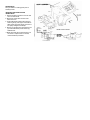
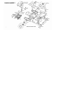
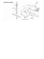
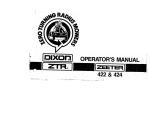
OPERATOR'S MANUAL FOR ZTR-301, 302 MOWER
IMPORTANT!
The Dixon ZTR mower is both easy and fun
to operate. However, any power mower must
be operated properly to be safe. It is not a toy
or a recreational vehicle. Before you start to
use the mower, read the operator's manual
carefully, and become completely
familiar with the controls. Your
Dixon dealer will gladly provide
a check-out ride, and answer
any questions.
READ CAREFULLY
You have purchased a top quality lawn mower that has been inspected at the factory and found to be in perfect mechanical condition. This
lawn mower is warranted for 1 year from date of delivery against all defects in materials and workmanship. Lawn mowers used for
commercial service are warranted for 30 days from date of delivery.
ONE-YEAR LIMITED WARRANTY
This lawn mower is warranted for one(1) year from date of delivery against all defects in materials and workmanship. Lawn mowers used
for commercial service are warranted for 30 days from date of delivery. (Lawn mowers other than those used only at residence of owner
are considered as commercial service.)
Each new mower is warranted against manufacturing defects in material and workmanship under normal use and service. Our obligation,
under this warranty, shall be limited to the replacement to the original retail purchaser of any part or parts, which, within the warranty
period, shall be shown to be defective due to faulty workmanship or materials at the factory. All parts claimed defective must be returned
to the factory for inspection, repair, or replacement with transportation charges prepaid.
This warranty does not apply to damage in transit or damage caused by misuse, negligence or accident, to alterations or repairs done
outside the factory or authorized service stations, nor does it obligate us to assume any transportation charges in connection with the
replacement of parts claimed to be defective.
Our warranty does not apply to the blades, adapters, chains or belts on our mowers due to the very nature of the function they perform
and to the elements they are exposed to.
The warranty specifically excludes engines and tires which are warranted separately by their respective manufacturers. All claims for
defective engines or engine parts must be made in accordance with the engine manufacturer's warranty.
We reserve the right to make changes in design and changes or improvements on our product without imposing any obligation upon
ourselves to install the same on products heretofore manufactured.
This warranty is null and void if any parts other than original manufacturer's parts are used. There is no other express warranty.
IMPLIED WARRANTIES, including those of merchantability and fitness for a particular purpose, are limited to one(1) . year from
purchase and, to the extent permitted by law, any and all implied warranties are excluded.
SERIAL NUMBERS
The lawn mower has two serial numbers:
Mower Number — Located on frame at right rear transaxle mount. Transaxle Number — Located on transaxle.
SAFETY INSTRUCTIONS
BEFORE MOWING:
1. Discuss proper maintenance with your Dixon dealer, to save
money and prevent injury. Consult your dealer before
removing any parts.
2. Don't allow anyone to operate your Dixon mower without
proper instruction. Young children should never be allowed
to operate any power mower, riding or walking.
3. Before mowing, pick up all debris — particularly stones and
sharp objects.
4. Before starting the engine, make sure the gas cap is
in place.
DURING MOWER OPERATION 1. The revolutionary Dixon
mower attracts many admiring
neighbors. But when mowing, all persons — especially
children — and pets should be cleared from the mowing
area.
2. Wear appropriate, safe clothing when mowing — close-fitting
jeans or slacks and heavy leather or safety shoes with rough
soles. Never use any kind of mower with bare feet or open
sandals, not even an old push-type model!
3. When grass is wet or slippery, do not use any riding mower.
4. Always mow at the slowest speed that will cut satisfactorily.
5. Keep hands and feet away from the blade at all times.
6. Although the Dixon mower is equipped with a missile deflector
which directs downwards all blade propelled objects, keep
persons clear of the discharge chute.
7. Your Dixon mower is very stable because of its low center of
gravity and weight biased to the rear; however, caution should
be exercised when mowing hills or slopes with any mower.
8. Always disengage blades before taking the mower
across walks or objects that project above the surface. 9. When the
mower is not in use, turn the engine off; never leave the engine running
unattended. Your Dixon mower is equipped with a weight-sensitive
switch that kills the engine when operator leaves the seat while blades
are engaged.
10. Before adjusting your mower or adding fuel, turn the engine off. Let
it cool, and disconnect the spark plug so the engine cannot start by
accident. Be sure all moving parts are stopped.
11. Never run the engine indoors; the fumes are dangerous.
12. Before backing your Dixon mower, stop, turn around, and
look.
13. Gasoline fumes are explosive; use only approved gasoline
containers to store small amount of fuel. No special oil/gas
mixtures are needed for your Dixon mower.
14. If the mower should start vibrating, stop the engine
immediately and check for damage or loose parts. Vibration
is usually the warning of trouble.
15. Never lift lawn mower by the body; lift only by the frame.
ALWAYS SET PARKING BRAKE AND DISENGAGE BLADE OPERATION BEFORE DISMOUNTING
IMPORTANT OPERATING INSTRUCTIONS
Dixon ZTR mowers offer a new concept in mowing, providing
unique maneuverability and ease. The following procedures will
allow one to become familiar with the unique method of control
very easily.
1. SET PARKING BRAKE — Be sure that drive levers are free.
(When drive levers are released, they will return to neutral
position.)
2. Move "Blade Operation" lever to "Disengage" position. ..
Engine will not start when blades are engaged.
3. Move throttle control to "Choke" position.
4. To start models with electric starting, simply insert ignition key
and turn to the far right position. When the engine starts,
release the ignition key and it will remain in the "RUN"
position. To stop the engine simply turn the key to the "OFF"
position.
To start manual start models, turn switch to "RUN" position. A
sharp pull will start the engine. Release the start-
ing rope as soon as engine starts. To stop engine turn key to
"OFF" position.
5. Set engine to desired speed by adjusting throttle control. (Suggest
set at slow speed during initial operation.)
6. NOTE SAFETY FEATURE: Engine stops automatically if
operator leaves seat while blades are engaged.
7. This unit is equipped with a unique transaxle that requires only two
drive levers to control braking, turning, direction and acceleration.
TO GO FORWARD:
From neutral position push both drive levers slightly forward; to
increase speed move levers further forward. TO GO
BACKWARD:
From neutral position pull both drive levers slightly rearward.
TURNING:
Turning is controlled by moving one drive lever slightly forward or
rearward of the other. To turn left, move left lever rearward of
right lever. To turn "square corners" move lever of desired
direction to neutral. To turn on mower's own axis (Zero radius)
reduce speed and move one lever to reverse position and the
other to forward position.
BRAKING:
To brake mower, move both levers in direction opposite of travel,
release levers to neutral, set parking brake. When stopping on
incline, it may be necessary to hold slight pressure on levers in
direction opposite of slope, until parking brake is set.
ALWAYS SET PARKING BRAKE BEFORE DISMOUNTING.
INITIAL OPERATION:
It is recommended that first operation of mower be done at a
slow setting of throttle speed and disengagement of mower
blades until operator is thoroughly familiar with the unit.
You may have tendency to "over control" mower at first.
Slight movements — fingertip control — is all that's
necessary for easy operation. 8. Mower Blade Operation:
• Cutting height is set by positioning the adjustment lever. Push
button knob on top of lever, set desired cutting height, lock into
position by releasing button knob.
• To start mower blades, move lever on floor to "engage"
position. To stop mower blades, move lever to "disengage"
position.
ALWAYS DISENGAGE BLADE OPERATION BEFORE
DISMOUNTING.
9. Parking Brake:
Parking brake is hand operated and is located at right-hand
side of mower. To disengage move lever forward. To engage
brake pull lever to the rear. Always set parking brake before
dismounting. Be sure that parking brake is disengaged
before moving mower.
MAINTENANCE
PRE-STARTING INSTRUCTIONS
1. Fill fuel tank with a good grade of regular gasoline. Do not
mix oil with gasoline.
2. Attach the spark plug wire to the spark plug.
3. With mower on a level surface, fill the crankcase with a good
grade of multi-purpose 10 - 30 oil as outlined in the engine
instruction manual.
4. On model equipped with a battery be sure the battery is filled
to proper fluid level with electrolite solution. After initial filling,
level may be retained with distilled water.
CAUTION:
5. During initial "Break In" period, the oil level should be checked
often.
6. Check oil level every five operating hours or each time mower
is used.
7. Change oil every 25 operating hours or sooner if equipment is
operated in extremely dusty conditions.
BELT ADJUSTMENT
Main Drive Belt - This belt should be kept taut to lengthen belt life
and prevent loss of power. To tension belt, loosen 4 bolts which
hold the engine to the mount and the lock nut on the tension bolt at
the rear of the machine. Tighten tension bolt until belt is taut and
retighten the 4 bolts holding engine and tighten tension bolt lock
nut.
MOWER DRIVE BELT
Belt tension for the mower drive belt is adjusted by turning the
turnbuckle to provide more forward movement of the engaging
idler.
REPLACE BELTS WHEN ADJUSTMENT CAN NO LONGER
BE MADE SATISFACTORILY OR IF BELTS BECOME
WORN.
BODY REMOVAL FOR ZTR-301 / 302
1. Disconnect throttle cable from engine by loosening clamp on
engine and disconnecting cable.
2. Disconnect two (2) switch loom plugs, one going to engine wires
and one going to frame wire loom. Plugs are located back of
transaxle mount.
3. Remove four (4) control lever bolts and remove upper control
levers.
4. Remove engaging handle by removing bolt and nut under handle.
5. Remove four (4) attach bolts on floor.
6. Remove two (2) sheet metal screws from transaxle mount. Body
will now lift clear. To replace body, reverse the above procedure.
Remember to reinstall switch ground wire on left rear transaxle body
mount screws.
CHAIN ADJUSTMENT
To adjust the drive chains, the body must be removed and shims
added behind the transaxle. Loosen 4 bolts which hold the transaxle
to the frame. Insert shims (Pt. No. 2221 or 2222) as needed for
adjustment between transaxle and mount plates. Tighten the 4 bolts
which hold the transaxle to the frame. A few drops of oil periodically
will lengthen
chain life. Replace chain when rollers become loose, chain breaks,
or chain fails to operate properly. WHEELS AND TIRES
Correct tire pressure is essential to correct operation of the mower.
The correct pressure for the drive tires is 14 -16 Ibs. Lug nuts
should be checked periodically. Front tires are semi-pneumatic and
do not require inflation. ELECTRICAL SYSTEMS
Keep all connections clean and tight. Maintain the fluid in the battery
at correct level.
BODY
The body may be washed with a mild detergent and waxed with any
automotive type wax.
ENGINE
Follow the manufacturer's instructions as to maintenance and
repair. A copy of these instructions are supplied with each
mower.
TRANSAXLE
For adjustment or repair confer with authorized Dixon dealer
service department. Adjustment or repair by other than
authorized dealer voids warranty.
SPARE PARTS
See your dealer for ordering spare parts or
warranty service.
REMOVING AND REINSTALLING
MOWER DECK
1. Remove engaging handle by removing bolt
and nut under handle.
2. Disconnect mower deck wire loom from
frame wire loom.
3. Loosen belt keeper located under engine by
loosening two (2) rear engine mount bolts to
allow mower deck drive belt to come free of
rear pulley. Retighten belt keeper.
4. Remove six (6) attach pins and clips from four
(4) mower deck attach points and two (2)
stabilizer bars.
5. Mower deck may then be removed from unit
for service or replacement. To reinstall,
reverse the above procedure.
Part No. Name
Part No. Name
Part No. Name
30-1039
30-1043
30-1501R
30-1501L
30-1507
30-1530
30-1536
30-1540
30-1542
30-1543
30-1560-1
30-1574
30-1604
30-1606
30-2000
30-2150
30-2152
30-2154
30-2155
30-2159
30-2161
30-2164
30-2165
30-2166
30-2201
30-2202
30-2203
30-2209
30-2212
30-2214
30-2216
30-2220
30-2221
30-2222
30-2224
30-2225
30-2402
30-2403
30-2404
30-2406
30-2408
30-2410
30-2411
30-2412
30-2413
30-2414
30-2416
30-2417
30-2418
30-2419
30-2421
30-2422
30--2425
30-2426
30-2429
30-2430
30-2432
30-2433
30-2434
30-2435
30-2436
30-2437
30-2438
30-2439
30-2443
30-2444
30-2445
30-2446
30-2500
30-2501
30-2504
30-2505
Lower Lift Link
Battery Strap
Upper Control Lever - Right
Upper Control Lever - Left
Wheel/Mower Deck Bearing
Bellcrank Weldment
Chain Connecting Link
Engine Shaft Key
V-Pulley
Lift Knob
Battery Splash Guard
Brake Pivot
Lower Control Pin
Brake Mount
Frame Weldment
Blue Body - ZTR-301/302
Caster Axle
Deck Hub Pulley Spacer
Deck Hub Bearing Spacer
Engaging Idler Spacer
Connecting Link
Support Sprocket Spacer
Torque Rod
Pivot Bolt
Lower Control Lever - Left
Lower Control Lever - Right
Wheel Hub & Sprocket Assembly
Lower Lever Pin
Lift Tie Rod
Brake Arm
Belt Keeper
Engine Tension Plate
Transaxle Shim (16 Ga.)
Transaxle Shim (22 Ga.)
Brake Clip
Battery Box Weldment
Rear Wheel & Tire
Caster Wheel & Tire
Caster Wheel Bearing
Blade
Drive Chain
ZTR-301/302 Seat
Deck V-Pulley
DeckV-Belt
V-ldler Pulley
Idler Tension Spring
Short Brake Rod
Control Rod Assembly
Long Brake Rod
Throttle Control
Model Decal, ZTR-301
Name Decal, ZTR-301/302
Tumbuckle
Drive V-Belt
Model Decal, ZTR-302
Rear Wire Loom, ZTR-301
Frame Wire Loom, ZTR-301
Engine Connector Plug
Cam Switch Spring
Control Decal, ZTR-301/302
Switch Decal
Switch Ground Wire, ZTR-302
Pan Wire Loom, ZTR-302
Frame Wire Loom, ZTR-302
Deck Caution Decal
Battery to Ground Wire
Fuel Tank Decal
Seat Switch Loom, ZTR-302
Transaxle
Rear Tube Weldment
Front Tube
Support Assembly - Left
Part No. Name
Part No. Name
Part No.
Name
30-2506
30-2507L
30-2507R
30-2509
30-2514
30-2515
30-2519
30-2520
30-2600
30-2601
30-2612
30-2618
30-2620
30-2626
30-2631
30-2640
30-2641
30-2642
30-2645
30-2647
30-2648
30-2812
30-2813
30-2815
30-3025
30-3026
30-3029
30-3032
30-3042
30-3054
30-3057
30-3059
30-3070
30-3072
30-3092
30-3094
30-3502
30-3504
30-3508
30-3511
30-4004
30-4006-1
30-4007
30-4008
30-4027
30-4036
30-5005
30-5007
30-5009L
30-5009R
30-5012
30-5013
30-5015
30-5016
30-5018
30-5019
30-5021
30-5022
30-5024
30-5025
30-5028
30-5028-A
30-5035
30-5036
30-5046
30-5047
30-6052
30-6059
Cradle - Left
Cradle - Right
Cradle Shaft
Frame Shaft
24 T Sprocket
Cone (Set of Two)
9 T Sprocket - Narrow
Chain
9 T Sprocket - Wide
Thumb Screw
Cradle Spring
Frame Assembly
Bearing
Bearing - Notched
Transaxle Pulley
Pivot Spring
Positive Neutral Rod
Positive Neutral Spring
Stabilizer Arm
Flat Idler Pulley
Support Assembly - Right
Support - Left
Support - Right
Support Shaft
Torque Rod Stiffener - RH
Torque Rod Stiffener - LH
Cradle Assembly - Left
Cradle Assembly - Right
Mower Deck Assembly
Mower Deck Weldment
Engaging Idler
Engaging Cam
Engaging Rod
Deflector
Pan Switch Spacer
Deck Hub Assembly
Deck Hub Sub-Assembly
Deck Hub
Blade Shaft
Blade Washer
Deck Hub Key
Oil Drain Assembly
Seat Switch Assembly, ZTR-301
Seat Switch Assembly, ZTR-302
1/4 x 1" Spiral Pin
1/4 x 1-1/2" Spiral Pin
Grommet
1/2" Lockwasher
Pivot Bolt Locknut (7/16-14)
3/16 x 1" Roll Pin
3/8" Flat Washer
Spring Clip
1/4 x 1-1/4" Spiral Pin
Hair Pin Cotters (Mower Deck)
1/2-20, 1-1/4 CL. 5 Bolt
1/2" Flat Washer
Hand Grip
Double Ball Joint
Floor Pad - Short
Adhesive Rear Grommet
Switch
Battery Solenoid Cable
Battery
Solenoid
Pan Wire Loom, ZTR-301
Micro Switch
Discup
Center Frame
30-6089
30-6107
Engaging Handle
Deck Pin
OWNER INFORMATION
Dixon and ZTR are the trademarks of
Form No. 1449-177
Dixon Industries, Inc., Box 494, Coffeyville, Kansas 67337
LITHO IN U.S.A.