1
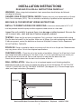
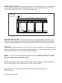
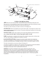
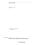
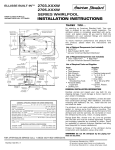
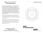
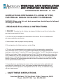
WHIRLPOOL BATH INSTALLATION
AND OPERATION INSTRUCTIONS
HYDROMASSAGE BATHTUB - UL 1795
INSTRUCTIONS PERTAINING TO A RISK OF FIRE,
ELECTRICAL SHOCK OR INJURY TO PERSONS.
WARNING- When using this unit, basic precautions should always be followed,
including the following:
1.
READ AND FOLLOW ALL INSTRUCTIONS.
2. DANGER: To reduce the risk of injury, do not permit children to use this unit unless they
are closely supervised at all times.
3. Use this unit for its intended use as described in this manual. Do not use attachments
not recommended by manufacturer.
4. Never drop or insert any object into any opening.
5. Do not operate unit without guard over suction fitting.
6. The unit must be connected only to a supply circuit that is protected by a ground-fault
circuit interrupter (GFCI). Such a GFCI should be provided by the installer and should be
tested on a routine basis. To test the GFCI, push the test button. The GFCI should interrupt power.
Push the reset button. Power should be restored. If the GFCI fails to operate in this manner, the
GFCI is defective. If the GFCI disrupts power to the bath without the test button being pushed a
ground current is flowing indicating the risk of electrical shock. Do not use this hydromassage
bathtub. Disconnect the hydromassage bathtub and have the problem corrected by a qualified
service representative before using.
7. A grounding lug is provided on the exterior of the control panel (where applicable) and
pump to permit connection of a No. 8 solid copper bonding conductor between this unit
and all other electrical equipment and exposed metal in the vicinity, as needed to comply
with local requirements.
8.
SAVE THESE INSTRUCTIONS.
American Whirlpool 216 Vine Street, Clifton, Tennessee, 38425
Phone - 800-327-1394 Fax - 800-398-5651
PRECAUTIONS
READ AND FOLLOW ALL INSTRUCTIONS CAREFULLY
Inspection: Upon receipt of the Whirlpool Bath, inspect it thoroughly for damage or shortage.
Verify that the unit specifications are correct. If damage or shortage has occurred notify the
distributer or freight carrier immediately.
Under no circumstances should a damaged or defective unit be installed without prior factory
approval. Neither Praxis Companies nor the distributer will be responsible for removal or
re-installation costs should replacement of the unit be necessary.
Testing: Follow all testing procedures. While each unit is factory water tested, the shipping
process may result in damage to, or loosinging of the pipe joints and connections.
Keep the unit covered during and after installation to prevent damage to the surface of the bath.
Do not lift the unit by the piping. Lift only by the bath’s deck.
Never attempt to run the pump/motor while the whirlpool is dry.
All plumbing and electrical connections should be made by licensed, qualified plumbers
and electricans.
Be sure the installation follows all applicable codes.
Service and repairs should be performed only by qualified service representatives.
Any questions regarding installation or operation of the whirlpool bath may be directed to:
American Whirlpool
Customer Service Department
1-800-327-1394
SAVE THESE INSTRUCTIONS AND ALL ACCOMPANYING MATERIAL.
2
INSTALLATION INSTRUCTIONS
READ AND FOLLOW ALL INSTRUCTIONS CAREFULLY
WARNING - When using electrical products, basic precautions should always be followed.
including the following:
DANGER: RISK OF ELECTRICAL SHOCK. Connect only to a circuit protected by a Ground
Fault Circuit Interrupter (GFCI). This unit should be installed by a qualified service representative.
SEE PAGE (5) FOR IMPORTANT WIRING INSTRUCTIONS.
INSTALL TO PERMIT ACCESS FOR SERVICING: A minimum access panel of 15” x 20”
must be provided should the pump or other equipment need service at a later date.
Inspect the unit carefully to ensure there is no damage or defects present. Be sure the
unit is correct size, color and has all features originally ordered.
TESTING: Water test the unit prior to installation. Set it up where it can be drained after testing.
Plug the drain hole and fill to the overflow. Make sure all fittings, thru-walls and piping are water tight.
If leaks are present, contact the distributer or American Whirlpool Customer Service Department.
DO NOT INSTALL THE BATH.
ROUGH IN: Rough in should be kept to a minimum until the unit is on the job site. Measurements
may vary plus or minus 1/4 inch from origional specifications.
CHECKING LEVEL: Place the unit in the location of installation. Using a 5 or 6 foot level, check
level (length and width) to determine if the floor is level. If it is not, calculate how much mortar you
will have to use to level the tub. Pour a small amount of water onto the deck of the tub.
Check that the water drains from the deck into the interior of the tub.
WALL INSTALLATION: When the unit is to be placed against a wall, blocking should be
attached to the wall in such a way as to allow the tub lip to rest on the blocking. DO NOT ALLOW
TUB LIP TO SUPPORT ANY OF THE BATH”S WEIGHT (See diagram #1). If a screw flange is provided, see flange instructions (See page 6).
Diagram #1
SEALANT
BLOCKING
American Whirlpool Customer Service Department - Telephone - 1-800-327-1394
3
DECK INSTALLATION: For deck mounted tubs, use the dimension of the unit and subtract
1-1/2 inches to reach your platform opening dimensions. e.g. Tub dimensions are 72” x 36”.
Platform opening will be: 70-1/2” x 34-1/2”. (See diagram #2)
Diagram #2
SEALANT
3/4”
FAUCET AND VALVES: Faucet and valves may be installed through the tub deck. Use a
sharp hole saw, making sure the spout will clear the deck edge before drilling. A heat resistant
material must be placed between the tub and any soldering work to prevent damage to the tub.
FINISHING: Before closing in the unit fill the tub 2” above the highest jet. Run the pump for 15
minutes and check for leaks. Shut off the pump, let stand for 5 minutes and check again for leaks.
When draining the bath, check tub’s base for proper drainage.
NOTE: The tub must be cleaned before operating the pump. NEVER OPERATE THE PUMP
WITHOUT THE SUCTION COVER IN PLACE.
After the unit has been tested, close in with the material of your choice. Seal around the tub lip
and surrounding walls (where applicable) with a water resistant sealer.
Clean out the unit using a damp cloth and liquid detergent. do not use solvents or
abrasive cleaners.
Fill tub and test operation.
4
ELECTRICAL CONNECTIONS
ALL WIRING MUST BE DONE BY A QUALIFIED, LICENSED ELECTRICIAN
BATH PUMP SPECIFICATIONS: 115/120 VAC 6.6 AMP 60 HZ -OR- 115/120 VAC 10.6 AMP 60
HZ, requires a dedicated circuit protected with a 15 AMP GFCI (Ground Fault Circuit Interrupter).
See Diagram #3.
For units equipped with luxury upgrades: 115/120 VOLT, 11.2 AMP, 60 HZ. requires a dedicated
circuit protected with a 20 amp GFCI (Ground Fault Circuit Interrupter).
See Diagram #4.
For all installations, install an outlet to the studwall a minimum of 6 inches above the floor,
located near the pump access opening.
IN-LINE HEATER (OPTIONAL) SPECIFICATIONS: 1.5 KW, 115/120 VOLT, 12.4 AMP. The InLine Heater must be connected to a 115/120 VAC, 20 AMP, dedicated circuit protected with a
GFCI (Ground Fault Circuit Interrupter). Install an outlet to the studwall. The outlet must be a
minimum of 6 inches above the floor and must be located near the access panel.
Note: Where applicable grounding lugs are provided on the exterior of the pump, in-line heater
and control box to permit connection of a No. 8 solid copper bonding conductor between this unit
and all other electrical equipment and exposed metal in the vicinity, as needed to comply with
local requirements.
STUD WALL
OUTLET
GROUNDING
LUG
Diagram #3
STANDARD ELECTRICAL
CONNECTION
STUD WALL
OUTLET
Diagram #4
GROUNDING
LUG
5
FOR UNITS EQUIPPED
WITH LUXURY UPGRADES
INSTALLATION WITH MOLDED ACRYLIC OR SCREW ON TILE FLANGE
1) Drill through flange at the framing studs.
2) Screw flange to framing studs.
3) For units equipped with the acrylic flange, bring the sheathing to the top of the flange and seal
the joint. (See diagram A).
4) For units equipped with the screw on tile flange, it is necessary to caulk between the flange and
tub after attaching the flange to the framing. Allow the sealant to dry, then bring the sheathing
over the flange. (See diagram B)
5) Tile over sheathing and/or flange, sealing all joints between the tub and tile.
TYPICAL INSTALLATION
WITH SCREW ON TILE FLANGE
(B)
TYPICAL INSTALLATION
WITH ACRYLIC SCREW FLANGE
(A)
SHEATHING
SHEATHING
TILE
TILE
FRAMING
FRAMING
SEALANT
TILE FLANGE
INTEGRAL SCREW FLANGE
SEALANT
1) Insert horizontal edge of skirt into top brackets. Once skirt is plumb, scribe a line on the floor
parallel to bottom of skirt.
2) Mount (3) lower braces to floor approximately 1/4” behind line (1 center of skirt - 1 on each
end of the toe kick.)
3) Lift skirt until seam between tub and skirt is minimal, screw (5) into place.
4) Place decorative caps over screw heads.
NOTE: Caulking may be used to completely conceal seam between tub and skirt.
In some cases it may be necessary to widen the recess in the top brackets, if so,
use a hand saw and cut in 1/8” increments. DO NOT deepen recess.
UPPER BRACKETS
DECORATIVE SCREW CAP
MOUNTING
TOP BRACKET RECESS
SCREW
RECESSED TOE KICK
LOWER BRACES
LOWER BRACE
FRONT VIEW
BACK VIEW
6
OPERATING INSTRUCTIONS
IMPORTANT SAFETY INSTRUCTIONS: Please refer to important safety
instructions included on the cover of this manual before operating or using the whirlpool bath.
* Maximum soaking temperature should not exceed 104 degrees (F) 40 degrees (C). Consult a
physician for specific temperature and length of use specifications, depending on health considerations.
* Children, elderly or infirm bathers must remain under close supervision.
* Keep hair away from suction fitting to prevent entrapment.
* Do not use while under the influence of alcohol or drugs.
* Use precaution while entering or exiting the bath to prevent accidental slips or falls.
* Periodically check Ground Fault Circuit Interrupter to insure it is operating correctly.
* Keep electrical appliances at least (5) feet away from bath while bathing.
* Do not use oil based additives in the whirlpool bath.
OPERATION: Fill the bath high enough to cover the highest wall jet allowing for body displacement of the
water so as not to over flow the bath but covering the highest jet. turn the pump motor on by one of two controls.
The pump will run until the button is pressed again.
1) Airswitch - A push button located on the bath. to turn on bath, depress the button.
The pump will run until the button is depressed again.
2) Ameri-Touch low water cutoff. A sensor pad located on the bath’s deck. To turn on the bath, fill the tub
high enough to cover the highest wall jet allowing for body displacement of the water so as not to
overflow the bath but covering the highest jet. touch the sensor pad and the pump will turn on.
The built in timer will allow the bath to run for 20 minutes, then shut off automatically. If additional
time is desired, touch the sensor pad again. If you wish to shut off the pump before time has expired, touch
the sensor pad and the pump will shut off.
For units equipped with Back jets, Neck Jets, Foot Jets, or air Jets, the bath’s pump must be turned on
prior to activating these features.
CARE AND MAINTENANCE
To clean the acrylic surface, use a damp cloth or sponge with household soap or liquid detergent.
Do not use abrasive cleaners or solvents.
A paste wax or automobile rubbing compound may be used to remove light surface scratches.
THE WHIRLPOOL SYSTEM SHOULD BE FLUSHED PERIODICALLY (NOT TO
EXCEED 90 DAYS). To clean the whirlpool piping system, fill the tub with water 2 inches above the highest
jet and add 1/2 oz. liquid dishwasher liquid per gallon of water. Run the system for 10 minutes then drain the
bath.
SERVICE AND REPAIRS SHOULD BE PERFORMED BY A QUALIFIED SERVICE TECHNICIAN.
American Whirlpool Customer Service Department - Telephone - 1-800-327-1394
7
TUB
ON/OFF CONTROL (BUTTON -or- AMER-TOUCH PAD
FROM
SUCTION
OVERFLOW
TO JETS
FLOOR
JETS
PUMP
REINFORCED
PUMP
PLATFORM
SUCTION
REINFORCED
BASE
TUB
LEGS
DRAIN
TO WASTE
TYPICAL TUB INSTALLATION
JETS: Where the water enters the bath. The jet direction can be controlled by rotating the nozzle.
Water pressure can be regulated by turning the escheon (ring/bezzle around the jet) clockwise to reduce
the water pressure and counter clockwise to increase the water pressure.
The heater is set from the factory to maintain a maximum of 104 degrees (F).
AIR INDUCTION: Allows the introduction of air into the water system. The mixing of air creates a more
vigorous, bubbling stream of water from the jets. The system automatically introduces air into the system
while the pump is operating.
SUCTION FITTING: Feeds water to the pump. The suction fitting should be kept clean and free of
debris. DO NOT RUN THE PUMP IF THE SUCTION COVER IS NOT IN PLACE.
PUMP: No maintenance is required on the tub pump. Do not allow the pump to be run without water
in the tub. When bathing is completed, be sure pump is turned off.
IN LINE HEATER (OPTIONAL): Designed to maintain the bath’s original water temperature.
The heater is controlled by an internal pressure switch that detects the movement of water through
the system activating the heater. accordingly, the heater will not turn on unless the pump is running.
The heater’s thermostat has a maximum setting of 104 degrees (F).
This heater is equipped with a High-limit switch. Should the water temperature exceed safe standards,
the High-Limit switch will shut off the heater. If tripped, push in the button to reset.
If the High-Limit trips again, contact a qualified service technician.
CAUTION: The maximum temperature of the tub water should not exceed 104 F (40 C).
Temperatures of 100 F (38 C) to 104 F are considered safe for a healthy adult. Lower water
temperatures are recommended for extended use and young children. Prolonged exposures to hot
water may induce hyperthermia. Hyperthermia occurs when the internal temperature of the body
reaches a level several degrees above normal body temperature (98.6 F). Consult your physician
for guidelines.
AWPWHPL Rev 8-1-08.
8