1
Si34 - 601A
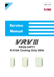
RXYQ5-54PY1
R-410A Heat Pump 50Hz
Si34-601A
R-410A Heat Pump
50Hz
1. Introduction ............................................................................................ vi
1.1 Safety Cautions ....................................................................................... vi
1.2 PREFACE ................................................................................................x
Part 1 General Information ........................................................... 1
1. Model Names of Indoor/Outdoor Units....................................................2
2. External Appearance...............................................................................3
2.1 Indoor Units ..............................................................................................3
2.2 Outdoor Units ...........................................................................................4
3. Combination of Outdoor Units.................................................................5
4. Model Selection.......................................................................................7
Part 2 Specifications .................................................................. 11
1. Specifications ........................................................................................12
1.1 Outdoor Units .........................................................................................12
1.2 Indoor Units ............................................................................................33
Part 3 Refrigerant Circuit ........................................................... 59
1. Refrigerant Circuit .................................................................................60
1.1
1.2
1.3
1.4
1.5
RXYQ5P.................................................................................................60
RXYQ8P.................................................................................................62
RXYQ10P, 12P ......................................................................................64
RXYQ14P, 16P, 18P ..............................................................................66
Outdoor air processing unit FXMQ125MFV1~250MFV1........................68
2. Functional Parts Layout ........................................................................69
2.1
2.2
2.3
2.4
2.5
RXYQ5P.................................................................................................69
RXYQ8P.................................................................................................70
RXYQ10P, 12P (12P: EUROPE) ...........................................................71
RXYQ12P...............................................................................................72
RXYQ14P, 16P, 18P ..............................................................................73
3. Refrigerant Flow for Each Operation Mode...........................................74
Part 4 Function............................................................................ 91
1. Function general ...................................................................................92
1.1 Symbol ...................................................................................................92
1.2 Operation Mode......................................................................................93
2. Basic Control.........................................................................................94
2.1
2.2
2.3
2.4
2.5
Table of Contents
Normal Operation ...................................................................................94
Compressor PI Control...........................................................................95
Electronic Expansion Valve PI Control.................................................107
Step Control of Outdoor Unit Fans .......................................................107
Outdoor Unit Fan Control in Cooling Operation ...................................108
i
Si34-601A
3. Special Control....................................................................................109
3.1
3.2
3.3
3.4
3.5
3.6
3.7
Startup Control .....................................................................................109
Large capacity start up control (Heating) .............................................110
Oil Return Operation ............................................................................111
Defrosting Operation ............................................................................113
Pump-down Residual Operation ..........................................................114
Standby ................................................................................................115
Stopping Operation ..............................................................................116
4. Protection Control ...............................................................................118
4.1
4.2
4.3
4.4
4.5
4.6
High Pressure Protection Control.........................................................118
Low Pressure Protection Control..........................................................119
Discharge Pipe Protection Control .......................................................120
Inverter Protection Control ...................................................................121
STD Compressor Overload Protection.................................................122
Injection Control (only for RXYQ5P).....................................................122
5. Other Control.......................................................................................123
5.1
5.2
5.3
5.4
Outdoor Unit Rotation...........................................................................123
Emergency Operation ..........................................................................124
Demand Operation ...............................................................................128
Heating Operation Prohibition ..............................................................128
6. Outline of Control (Indoor Unit) ...........................................................129
6.1
6.2
6.3
6.4
6.5
6.6
6.7
6.8
6.9
6.10
6.11
Drain Pump Control..............................................................................129
Louver Control for Preventing Ceiling Dirt............................................131
Thermostat Sensor in Remote Controller.............................................132
Thermostat Control While in Normal Operation ...................................134
Thermostat Control in Dry Operation ...................................................134
Electronic Expansion Valve Control .....................................................135
Hot Start Control (In Heating Operation Only)......................................135
Freeze Prevention ................................................................................136
Heater Control ......................................................................................136
List of Swing Flap Operations ..............................................................137
Control of Outdoor Air Processing Unit
(Unique Control for Outdoor Air Processing Unit) ................................138
Part 5 Test Operation ............................................................... 143
1. Test Operation ....................................................................................144
1.1 Installation Process ..............................................................................144
1.2 Procedure and Outline .........................................................................145
1.3 Operation When Power is Turned On ..................................................159
2. Outdoor Unit PC Board Layout ...........................................................160
3. Field Setting ........................................................................................161
3.1 Field Setting from Remote Controller ...................................................161
3.2 Field Setting from Outdoor Unit............................................................174
Part 6 Troubleshooting ............................................................. 199
1. Symptom-based Troubleshooting .......................................................201
2. Troubleshooting by Remote Controller ...............................................204
2.1 The INSPECTION / TEST Button.........................................................204
2.2 Self-diagnosis by Wired Remote Controller .........................................205
2.3 Self-diagnosis by Wireless Remote Controller .....................................206
ii
Table of Contents
Si34-601A
2.4 Operation of The Remote Controller’s Inspection /
Test Operation Button ..........................................................................209
2.5 Remote Controller Service Mode .........................................................210
2.6 Remote Controller Self-Diagnosis Function .........................................212
3. Troubleshooting by Indication on the Remote Controller ....................220
3.1
3.2
3.3
3.4
3.5
3.6
3.7
3.8
3.9
3.10
3.11
3.12
3.13
3.14
3.15
3.16
3.17
3.18
3.19
3.20
3.21
3.22
3.23
3.24
3.25
3.26
3.27
3.28
3.29
3.30
3.31
3.32
3.33
3.34
3.35
3.36
3.37
Table of Contents
“A0” Indoor Unit: Error of External Protection Device ...........................220
“A1” Indoor Unit: PC Board Defect.........................................................221
“A3” Indoor Unit: Malfunction of Drain Level Control System (S1L) ......222
“A6” Indoor Unit: Fan Motor (M1F) Lock, Overload...............................224
“A7” Indoor Unit: Malfunction of Swing Flap Motor (M1S) .....................225
“A9” Indoor Unit: Malfunction of Moving Part of
Electronic Expansion Valve (Y1E)........................................................227
“AF” Indoor Unit: Drain Level above Limit..............................................229
“AJ” Indoor Unit: Malfunction of Capacity Determination Device ..........230
“C4” Indoor Unit: Malfunction of Thermistor (R2T)
for Heat Exchanger ..............................................................................231
“C5” Indoor Unit: Malfunction of Thermistor (R3T) for Gas Pipes..........232
“C9” Indoor Unit: Malfunction of Thermistor (R1T) for Suction Air.........233
“CJ” Indoor Unit: Malfunction of Thermostat Sensor
in Remote Controller ............................................................................234
“E1” Outdoor Unit: PC Board Defect ......................................................235
“E3” Outdoor Unit: Actuation of High Pressure Switch ..........................236
“E4” Outdoor Unit: Actuation of Low Pressure Sensor ..........................238
“E5” Outdoor Unit: Inverter Compressor Motor Lock.............................240
“E6” Outdoor Unit: STD Compressor Motor Overcurrent/Lock..............242
“E7” Outdoor Unit: Malfunction of Outdoor Unit Fan Motor ...................243
“E9” Outdoor Unit: Malfunction of Moving Part of
Electronic Expansion Valve (Y1E, Y2E)...............................................246
“F3” Outdoor Unit: Abnormal Discharge Pipe Temperature ..................248
“F6” Outdoor Unit: Refrigerant Overcharged.........................................249
“H7” Outdoor Unit: Abnormal Outdoor Fan Motor Signal.......................250
“H9” Outdoor Unit: Malfunction of Thermistor (R1T) for Outdoor Air.....251
“J2” Outdoor Unit: Current Sensor Malfunction ....................................252
“J3” Outdoor Unit: Malfunction of Discharge Pipe Thermistor
(R3, R31~33T) .....................................................................................253
“J5” Outdoor Unit: Malfunction of Thermistor (R2T), (R7T)
for Suction Pipe ....................................................................................254
“J6” Outdoor Unit: Malfunction of Thermistor (R4T) for
Outdoor Unit Heat Exchanger ..............................................................255
“J7” Outdoor Unit: Malfunction of Liquid Pipe Thermistor (R6T) ...........256
“J9” Outdoor Unit: Malfunction of Subcooling Heat Exchanger
Gas Pipe Thermistor (R5T) ..................................................................257
“JA” Outdoor Unit: Malfunction of High Pressure Sensor......................258
“JC” Outdoor Unit: Malfunction of Low Pressure Sensor.......................259
“L4” Outdoor Unit: Malfunction of Inverter Radiating Fin
Temperature Rise.................................................................................260
“L5” Outdoor Unit: Inverter Compressor Abnormal ...............................262
“L8” Outdoor Unit: Inverter Current Abnormal.......................................264
“L9” Outdoor Unit: Inverter Start up Error..............................................266
“LC” Outdoor Unit: Malfunction of Transmission Between Inverter
and Control PC Board ..........................................................................268
“P1” Outdoor Unit: Inverter Over-Ripple Protection ...............................271
iii
Si34-601A
3.38 “P4” Outdoor Unit: Malfunction of
Inverter Radiating Fin Temperature Rise Sensor.................................272
3.39 “PJ” Outdoor Unit: Faulty Field Setting after Replacing Main PC Board
or Faulty Combination of PC Board......................................................274
3.40 “UO” Outdoor Unit: Low Pressure Drop Due to Refrigerant Shortage
or Electronic Expansion Valve Failure..................................................275
3.41 “U1” Reverse Phase, Open Phase.........................................................276
3.42 “U2” Outdoor Unit: Power Supply Insufficient or
Instantaneous Failure...........................................................................277
3.43 “U3” Outdoor Unit: Check Operation not Executed ...............................280
3.44 “U4” Malfunction of Transmission Between Indoor Units ......................281
3.45 “U5” Indoor Unit: Malfunction of Transmission Between
Remote Controller and Indoor Unit.......................................................283
3.46 “U7” Indoor Unit: Malfunction of Transmission
Between Outdoor Units ........................................................................284
3.47 “U8” Indoor Unit: Malfunction of Transmission Between Main and
Sub Remote Controllers .......................................................................286
3.48 “U9” Indoor Unit: Malfunction of Transmission Between Indoor
and Outdoor Units in the Same System ...............................................287
3.49 “UA” Improper Combination of Indoor and Outdoor Units,
Indoor Units and Remote Controller.....................................................288
3.50 “UC” Address Duplication of Centralized Controller ...............................290
3.51 “UE” Malfunction of Transmission Between Centralized Controller
and Indoor Unit.....................................................................................291
3.52 “UF” System is not Set yet .....................................................................294
3.53 “UH” Malfunction of System, Refrigerant System Address Undefined...295
4. Troubleshooting (OP: Central Remote Controller) ..............................297
4.1 “M1” PC Board Defect ............................................................................297
4.2 “M8” Malfunction of Transmission Between Optional Controllers
for Centralized Control .........................................................................298
4.3 “MA” Improper Combination of Optional Controllers
for Centralized Control .........................................................................300
4.4 “MC” Address Duplication, Improper Setting ..........................................302
5. Troubleshooting (OP: Unified ON/OFF Controller) .............................305
5.1 Operation Lamp Blinks .........................................................................305
5.2 Display “Under Centralized Control” Blinks (Repeats Single Blink) .....307
5.3 Display “Under Centralized Control” Blinks (Repeats Double Blink) ....310
Part 7 Appendix......................................................................... 315
1. Piping Diagrams..................................................................................316
1.1 Outdoor Unit .........................................................................................316
1.2 Indoor Unit............................................................................................320
2. Wiring Diagrams for Reference...........................................................324
2.1 Outdoor Unit .........................................................................................324
2.2 Field Wiring ..........................................................................................329
2.3 Indoor Unit............................................................................................332
3. List of Electrical and Functional Parts .................................................348
3.1 Outdoor Unit .........................................................................................348
3.2 Indoor Side ...........................................................................................351
4. Option List ...........................................................................................357
4.1 Option List of Controllers......................................................................357
iv
Table of Contents
Si34-601A
4.2 Option Lists (Outdoor Unit)...................................................................359
5. Piping Installation Point.......................................................................361
5.1 Piping Installation Point ........................................................................361
5.2 The Example of A Wrong Pattern.........................................................362
6.
7.
8.
9.
Example of connection (R-410A Type) ...............................................363
Thermistor Resistance / Temperature Characteristics........................365
Pressure Sensor .................................................................................367
Method of Checking The Inverter’s Power Transistors
and Diode Modules .............................................................................368
Part 8 Precautions for New Refrigerant (R-410A) .................... 371
1. Precautions for New Refrigerant (R-410A) .........................................372
1.1 Outline ..................................................................................................372
1.2 Refrigerant Cylinders............................................................................374
1.3 Service Tools........................................................................................375
Index
............................................................................................. i
Drawings & Flow Charts ................................................................ v
Table of Contents
v
Introduction
Si34-601A
1. Introduction
1.1
Safety Cautions
Cautions and
Warnings
Be sure to read the following safety cautions before conducting repair work.
The caution items are classified into “
Warning” and “
Caution”. The “
Warning”
items are especially important since they can lead to death or serious injury if they are not
followed closely. The “
Caution” items can also lead to serious accidents under some
conditions if they are not followed. Therefore, be sure to observe all the safety caution items
described below.
About the pictograms
This symbol indicates an item for which caution must be exercised.
The pictogram shows the item to which attention must be paid.
This symbol indicates a prohibited action.
The prohibited item or action is shown inside or near the symbol.
This symbol indicates an action that must be taken, or an instruction.
The instruction is shown inside or near the symbol.
After the repair work is complete, be sure to conduct a test operation to ensure that the
equipment operates normally, and explain the cautions for operating the product to the
customer
1.1.1 Caution in Repair
Warning
Be sure to disconnect the power cable plug from the plug socket before
disassembling the equipment for a repair.
Working on the equipment that is connected to a power supply can cause an
electrical shook.
If it is necessary to supply power to the equipment to conduct the repair or
inspecting the circuits, do not touch any electrically charged sections of the
equipment.
If the refrigerant gas discharges during the repair work, do not touch the
discharging refrigerant gas.
The refrigerant gas can cause frostbite.
When disconnecting the suction or discharge pipe of the compressor at the
welded section, release the refrigerant gas completely at a well-ventilated
place first.
If there is a gas remaining inside the compressor, the refrigerant gas or
refrigerating machine oil discharges when the pipe is disconnected, and it can
cause injury.
If the refrigerant gas leaks during the repair work, ventilate the area. The
refrigerant gas can generate toxic gases when it contacts flames.
The step-up capacitor supplies high-voltage electricity to the electrical
components of the outdoor unit.
Be sure to discharge the capacitor completely before conducting repair work.
A charged capacitor can cause an electrical shock.
Do not start or stop the air conditioner operation by plugging or unplugging the
power cable plug.
Plugging or unplugging the power cable plug to operate the equipment can
cause an electrical shock or fire.
vi
Si34-601A
Introduction
Caution
Do not repair the electrical components with wet hands.
Working on the equipment with wet hands can cause an electrical shock.
Do not clean the air conditioner by splashing water.
Washing the unit with water can cause an electrical shock.
Be sure to provide the grounding when repairing the equipment in a humid or
wet place, to avoid electrical shocks.
Be sure to turn off the power switch and unplug the power cable when cleaning
the equipment.
The internal fan rotates at a high speed, and cause injury.
Do not tilt the unit when removing it.
The water inside the unit can spill and wet the furniture and floor.
Be sure to check that the refrigerating cycle section has cooled down
sufficiently before conducting repair work.
Working on the unit when the refrigerating cycle section is hot can cause burns.
Use the welder in a well-ventilated place.
Using the welder in an enclosed room can cause oxygen deficiency.
1.1.2 Cautions Regarding Products after Repair
Warning
Be sure to use parts listed in the service parts list of the applicable model and
appropriate tools to conduct repair work. Never attempt to modify the
equipment.
The use of inappropriate parts or tools can cause an electrical shock,
excessive heat generation or fire.
When relocating the equipment, make sure that the new installation site has
sufficient strength to withstand the weight of the equipment.
If the installation site does not have sufficient strength and if the installation
work is not conducted securely, the equipment can fall and cause injury.
Be sure to install the product correctly by using the provided standard
installation frame.
Incorrect use of the installation frame and improper installation can cause the
equipment to fall, resulting in injury.
Be sure to install the product securely in the installation frame mounted on a
window frame.
If the unit is not securely mounted, it can fall and cause injury.
Be sure to use an exclusive power circuit for the equipment, and follow the
technical standards related to the electrical equipment, the internal wiring
regulations and the instruction manual for installation when conducting
electrical work.
Insufficient power circuit capacity and improper electrical work can cause an
electrical shock or fire.
For integral units
only
For integral units
only
vii
Introduction
Si34-601A
Warning
Be sure to use the specified cable to connect between the indoor and outdoor
units. Make the connections securely and route the cable properly so that there
is no force pulling the cable at the connection terminals.
Improper connections can cause excessive heat generation or fire.
When connecting the cable between the indoor and outdoor units, make sure
that the terminal cover does not lift off or dismount because of the cable.
If the cover is not mounted properly, the terminal connection section can cause
an electrical shock, excessive heat generation or fire.
Do not damage or modify the power cable.
Damaged or modified power cable can cause an electrical shock or fire.
Placing heavy items on the power cable, and heating or pulling the power cable
can damage the cable.
Do not mix air or gas other than the specified refrigerant (R-410A) in the
refrigerant system.
If air enters the refrigerating system, an excessively high pressure results,
causing equipment damage and injury.
If the refrigerant gas leaks, be sure to locate the leak and repair it before
charging the refrigerant. After charging refrigerant, make sure that there is no
refrigerant leak.
If the leak cannot be located and the repair work must be stopped, be sure to
perform pump-down and close the service valve, to prevent the refrigerant gas
from leaking into the room. The refrigerant gas itself is harmless, but it can
generate toxic gases when it contacts flames, such as fan and other heaters,
stoves and ranges.
When replacing the coin battery in the remote controller, be sure to disposed
of the old battery to prevent children from swallowing it.
If a child swallows the coin battery, see a doctor immediately.
Caution
Installation of a leakage breaker is necessary in some cases depending on the
conditions of the installation site, to prevent electrical shocks.
Do not install the equipment in a place where there is a possibility of
combustible gas leaks.
If a combustible gas leaks and remains around the unit, it can cause a fire.
Be sure to install the packing and seal on the installation frame properly.
For integral units
If the packing and seal are not installed properly, water can enter the room and only
wet the furniture and floor.
1.1.3 Inspection after Repair
Warning
Check to make sure that the power cable plug is not dirty or loose, then insert
the plug into a power outlet all the way.
If the plug has dust or loose connection, it can cause an electrical shock or fire.
If the power cable and lead wires have scratches or deteriorated, be sure to
replace them.
Damaged cable and wires can cause an electrical shock, excessive heat
generation or fire.
Do not use a joined power cable or extension cable, or share the same power
outlet with other electrical appliances, since it can cause an electrical shock,
excessive heat generation or fire.
viii
Si34-601A
Introduction
Caution
Check to see if the parts and wires are mounted and connected properly, and
if the connections at the soldered or crimped terminals are secure.
Improper installation and connections can cause excessive heat generation,
fire or an electrical shock.
If the installation platform or frame has corroded, replace it.
Corroded installation platform or frame can cause the unit to fall, resulting in
injury.
Check the grounding, and repair it if the equipment is not properly grounded.
Improper grounding can cause an electrical shock.
Be sure to measure the insulation resistance after the repair, and make sure
that the resistance is 1 Mohm or higher.
Faulty insulation can cause an electrical shock.
Be sure to check the drainage of the indoor unit after the repair.
Faulty drainage can cause the water to enter the room and wet the furniture
and floor.
1.1.4 Using Icons
Icons are used to attract the attention of the reader to specific information. The meaning of each
icon is described in the table below:
1.1.5 Using Icons List
Icon
Type of
Information
Note
Description
A “note” provides information that is not indispensable, but may
nevertheless be valuable to the reader, such as tips and tricks.
Note:
Caution
A “caution” is used when there is danger that the reader, through
incorrect manipulation, may damage equipment, loose data, get
an unexpected result or has to restart (part of) a procedure.
Warning
A “warning” is used when there is danger of personal injury.
Reference
A “reference” guides the reader to other places in this binder or
in this manual, where he/she will find additional information on a
specific topic.
Caution
Warning
ix
Introduction
1.2
Si34-601A
PREFACE
Thank you for your continued patronage of Daikin products.
This is the new service manual for Daikin's Year 2006 VRVIII series Heat Pump System.
Daikin offers a wide range of models to respond to building and office air conditioning needs.
We are confident that customers will be able to find the models that best suit their needs.
This service manual contains information regarding the servicing of VRVIII series R-410A Heat
Pump System.
July, 2007
After Sales Service Division
x
Si34-601A
Part 1
General Information
1. Model Names of Indoor/Outdoor Units....................................................2
2. External Appearance...............................................................................3
2.1 Indoor Units ..............................................................................................3
2.2 Outdoor Units ...........................................................................................4
3. Combination of Outdoor Units.................................................................5
4. Model Selection.......................................................................................7
General Information
1
Model Names of Indoor/Outdoor Units
Si34-601A
1. Model Names of Indoor/Outdoor Units
Indoor Units
Type
Ceiling Mounted
Cassette Type
(Double Flow)
Ceiling Mounted
Cassette Type
(Multi Flow)
600×600 Ceiling
Mounted Cassette
Type
Model Name
Power Supply
FXCQ
20M
25M
32M
40M
50M
63M
80M
—
125M
—
—
FXFQ
—
25M
32M
40M
50M
63M
80M
100M
125M
—
—
FXZQ
20M
25M
32M
40M
50M
—
—
—
—
—
—
FXKQ
—
—
63MA
—
—
—
—
—
FXDQPVE
20P
25P
32P
—
—
—
—
—
—
—
—
FXDQPVET
20P
25P
32P
—
—
—
—
—
—
—
—
FXDQNAVE
20NA
25NA
32NA
40NA
50NA
63NA
—
—
—
—
—
FXDQNVET
20N
25N
32N
40N
50N
63N
—
—
—
—
—
Ceiling Mounted
Built-In Type
FXSQ
20M
25M
32M
40M
50M
63M
80M
100M
125M
—
—
Ceiling Mounted
Duct Type
FXMQ
—
—
—
Ceiling Suspended
Type
FXHQ
—
—
32MA
Wall Mounted Type
Ceiling Mounted
Cassette Corner Type
Slim Ceiling Mounted
Duct Type
VE
25MA 32MA 40MA
V1
VE
40MA 50MA 63MA 80MA 100MA 125MA 200MA 250MA
—
—
63MA
—
100MA
—
—
—
FXAQ
20MA 25MA 32MA 40MA 50MA 63MA
—
—
—
—
—
Floor Standing Type
FXLQ
20MA 25MA 32MA 40MA 50MA 63MA
—
—
—
—
—
Concealed Floor
Standing Type
FXNQ
20MA 25MA 32MA 40MA 50MA 63MA
—
—
—
—
—
Outdoor Air Processing
Unit
FXMQMF
—
—
—
—
—
—
—
—
Ceiling Suspended
Cassette Type
FXUQ
—
—
—
—
—
—
71MA 100MA 125MA
—
—
Connection Unit
BEVQ-MA
—
—
—
—
—
—
71MA 100MA 125MA
—
—
125MF 200MF 250MF
V1
VE
Note:FXDQ has following 2 Series, as show below.
FXDQ-P, N(A)VET: without Drain Pump (For General, Asia: except for EU, China and Australia)
FXDQ-P, N(A)VE: with Drain Pump
BEV unit is required for each indoor unit.
MA, NA: RoHS Directive models; Specifications, Dimensions and other functions are not changed compared
with M, N type.
Outdoor Units
Normal Series
Series
Heat Pump
RXYQ
5P
24P
42P
8P
26P
44P
10P
28P
46P
Model Name
12P
14P
30P
32P
48P
50P
Power Supply
16P
34P
52P
18P
36P
54P
20P
38P
22P
40P
30PH
48PH
32PH
50PH
34PH
36PH
Y1(E)
High COP Series (Energy Saving Series)
Series
Model Name
16PH
38PH
18PH
40PH
24PH
42PH
Heat Pump
RXYQ
∗Power Supply
VE: 1 phase 220~240V, 50Hz
V1: 1 phase 220~240V, 50Hz
Y1: 3 phase 380~415V, 50Hz
2
26PH
44PH
28PH
46PH
Power Supply
E:
Y1(E)
The unit with anti corrosion treatment
General Information
Si34-601A
External Appearance
2. External Appearance
2.1
Indoor Units
Ceiling Mounted Cassette Type (Double Flow)
FXCQ20M
FXCQ25M
FXCQ32M
FXCQ40M
FXCQ50M
FXCQ63M
FXCQ80M
FXCQ125M
Outdoor air processing
unit
FXMQ125MF
FXMQ200MF
FXMQ250MF
Ceiling Mounted Cassette
Type (Multi Flow)
Ceiling Suspended Type
FXHQ32MA
FXHQ63MA
FXHQ100MA
FXFQ25M
FXFQ32M
FXFQ40M
FXFQ50M
FXFQ63M
FXFQ80M
FXFQ100M
FXFQ125M
600×600 Ceiling Mounted
Cassette Type (Multi Flow)
Wall Mounted Type
FXAQ20MA
FXAQ25MA
FXAQ32MA
FXAQ40MA
FXAQ50MA
FXAQ63MA
FXZQ20M
FXZQ25M
FXZQ32M
FXZQ40M
FXZQ50M
Ceiling Mounted Cassette Corner Type
FXKQ25MA
FXKQ32MA
FXKQ40MA
FXKQ63MA
Floor Standing Type
FXLQ20MA
FXLQ25MA
FXLQ32MA
FXLQ40MA
FXLQ50MA
FXLQ63MA
Slim Ceiling Mounted Duct Type
Concealed Floor Standing Type
FXDQ20P FXDQ20N(A)
FXDQ25P FXDQ25N(A)
FXDQ32P FXDQ32N(A)
FXDQ40N(A)
FXDQ50N(A)
FXDQ63N(A)
with Drain Pump (VE)
without Drain Pump (VET)
FXNQ20MA
FXNQ25MA
FXNQ32MA
FXNQ40MA
FXNQ50MA
FXNQ63MA
Ceiling Mounted Built-In Type
Ceiling Suspended Cassette Type
(Connection Unit Series)
FXSQ20M
FXSQ25M
FXSQ32M
FXSQ40M
FXSQ50M
FXSQ63M
FXSQ80M
FXSQ100M
FXSQ125M
FXUQ71MA +
FXUQ100MA +
FXUQ125MA +
BEVQ71MA
BEVQ100MA
BEVQ125MA
Connection Unit
Ceiling Mounted Duct Type
FXMQ40MA
FXMQ50MA
FXMQ63MA
FXMQ80MA
FXMQ100MA
FXMQ125MA
FXMQ200MA
FXMQ250MA
FXMQ40~125M
FXMQ200 · 250M
General Information
3
External Appearance
2.2
4
Si34-601A
Outdoor Units
RXYQ5P
RXYQ8P, 10P (12P: EUROPE)
RXYQ12P, 14P, 16P, 18P
5HP
8, 10HP
12, 14, 16, 18HP
RXYQ20P, 22P, 24P, 26P, 28P
RXYQ30P, 32P, 34P, 36P
20, 22, 24, 26, 28HP
30, 32, 34, 36HP
RXYQ38P, 40P, 42P, 44P, 46P
RXYQ48P, 50P, 52P, 54P
38, 40, 42, 44, 46HP
48, 50, 52, 54HP
General Information
Si34-601A
Combination of Outdoor Units
3. Combination of Outdoor Units
Normal Series
System Number
Capacity of units
5HP
1
8HP
1
10HP
1
12HP
1
14HP
1
16HP
1
18HP
1
20HP
2
22HP
2
24HP
2
26HP
2
28HP
2
30HP
2
32HP
2
34HP
2
36HP
2
38HP
3
40HP
3
42HP
3
44HP
3
46HP
3
48HP
3
50HP
3
52HP
3
54HP
3
Note:
General Information
5
●
8
10
Module
12
14
16
18
Outdoor Unit Multi Connection
Piping Kit (Option)
●
●
●
—
●
●
●
●
●
●
●
●
●
●
●
●
●
●
●
●●
●
●
●
●
●
●
●●
●
●
●
●
●
Heat Pump: BHFP22P100
●
●●
●
●
●●
●●
●●
●●
●●
●●●
Heat Pump: BHFP22P151
For multiple connection of 18HP system or more, an optional Daikin Outdoor Unit Multi
Connection Piping Kit is required.
5
Combination of Outdoor Units
Si34-601A
High COP Series (Energy Saving Series)
System Number
Capacity of units
16HP
2
18HP
2
24HP
3
26HP
3
28HP
3
30HP
3
32HP
3
34HP
3
36HP
3
38HP
3
40HP
3
42HP
3
44HP
3
46HP
3
48HP
3
50HP
3
Note:
6
8
●●
●
●●●
●●
●●
●
●
10
Module
12
14
16
18
Outdoor Unit Multi Connection
Piping Kit (Option)
●
●
●
●
●
●
●●
●●
●●●
●●
●●
●●
●
●
Heat Pump: BHFP22P100
●
●
●
●●
●
●●●
●●
Heat Pump: BHFP22P151
●
●
For multiple connection of 16HP system or more, an optional Daikin Outdoor Unit Multi
Connection Piping Kit is required.
General Information
Si34-601A
Model Selection
4. Model Selection
VRV III Heat Pump Series
Connectable indoor units number and capacity
Normal Series
HP
5HP
8HP
10HP
12HP
14HP
System name
RXYQ5P
RXYQ8P
RXYQ10P
RXYQ12P
Outdoor unit 1
RXYQ5P
RXYQ8P
RXYQ10P
RXYQ12P
Outdoor unit 2
–
–
–
Outdoor unit 3
–
–
Total number of connectable
indoor units
8
Total capacity of connectable
indoor units (kW)
7.00~18.20
HP
16HP
18HP
RXYQ14P
RXYQ16P
RXYQ18P
RXYQ14P
RXYQ16P
RXYQ18P
–
–
–
–
–
–
–
–
–
13
16
19
23
26
29
11.20~29.12
14.00~36.40
16.75~43.55
20.00~52.00
22.40~58.24
25.20~65.52
20HP
22HP
24HP
26HP
28HP
30HP
32HP
RXYQ20P
RXYQ22P
RXYQ24P
RXYQ26P
RXYQ28P
RXYQ30P
RXYQ32P
Outdoor unit 1
RXYQ8P
RXYQ10P
RXYQ8P
RXYQ8P
RXYQ10P
RXYQ12P
RXYQ16P
Outdoor unit 2
RXYQ12P
RXYQ12P
RXYQ16P
RXYQ18P
RXYQ18P
RXYQ18P
RXYQ16P
Outdoor unit 3
–
–
–
–
–
–
–
Total number of connectable
indoor units
32
35
39
42
45
48
52
Total capacity of connectable
indoor units (kW)
27.95~72.67
30.75~79.95
33.60~87.36
36.40~94.64
39.15~101.79
41.95~109.07
44.70~116.22
System name
34HP
36HP
38HP
40HP
42HP
44HP
46HP
System name
HP
RXYQ34P
RXYQ36P
RXYQ38P
RXYQ40P
RXYQ42P
RXYQ44P
RXYQ46P
Outdoor unit 1
RXYQ16P
RXYQ18P
RXYQ8P
RXYQ8P
RXYQ8P
RXYQ8P
RXYQ10P
Outdoor unit 2
RXYQ18P
RXYQ18P
RXYQ12P
RXYQ16P
RXYQ16P
RXYQ18P
RXYQ18P
Outdoor unit 3
–
–
RXYQ18P
RXYQ16P
RXYQ18P
RXYQ18P
RXYQ18P
Total number of connectable
indoor units
55
58
61
50.25~130.65
53.50~139.10
61.75~160.55
63.75~165.75
Total capacity of connectable
47.50~123.50
indoor units (kW)
HP
64
56.00~145.60
48HP
50HP
52HP
54HP
System name
RXYQ48P
RXYQ50P
RXYQ52P
RXYQ54P
Outdoor unit 1
RXYQ12P
RXYQ14P
RXYQ16P
RXYQ18P
Outdoor unit 2
RXYQ18P
RXYQ18P
RXYQ18P
RXYQ18P
Outdoor unit 3
RXYQ18P
RXYQ18P
RXYQ18P
RXYQ18P
71.50~185.90
73.50~191.10
Total number of connectable
indoor units
Total capacity of connectable
67.50~175.50
indoor units (kW)
General Information
58.00~150.80
64
69.50~180.70
7
Model Selection
Si34-601A
High COP Series (Energy Saving Series)
16HP
18HP
System name
HP
RXYQ16PH
RXYQ18PH
Outdoor unit 1
RXYQ8P
RXYQ8P
Outdoor unit 2
RXYQ8P
RXYQ10P
Outdoor unit 3
–
–
Total number of connectable
indoor units
26
29
Total capacity of connectable
indoor units (kW)
22.40~58.24
25.20~65.52
24HP
26HP
28HP
30HP
32HP
System name
HP
RXYQ24PH
RXYQ26PH
RXYQ28PH
RXYQ30PH
RXYQ32PH
Outdoor unit 1
RXYQ8P
RXYQ8P
RXYQ8P
RXYQ8P
RXYQ8P
Outdoor unit 2
RXYQ8P
RXYQ8P
RXYQ8P
RXYQ10P
RXYQ12P
Outdoor unit 3
RXYQ8P
RXYQ10P
RXYQ12P
RXYQ12P
RXYQ12P
Total number of connectable
indoor units
39
42
45
48
52
Total capacity of connectable
indoor units (kW)
33.60~87.36
36.40~94.64
39.15~101.79
41.95~109.07
44.70~116.22
34HP
36HP
38HP
40HP
42HP
44HP
46HP
System name
HP
RXYQ34PH
RXYQ36PH
RXYQ38PH
RXYQ40PH
RXYQ42PH
RXYQ44PH
RXYQ46PH
Outdoor unit 1
RXYQ10P
RXYQ12P
RXYQ12P
RXYQ12P
RXYQ12P
RXYQ12P
RXYQ12P
Outdoor unit 2
RXYQ12P
RXYQ12P
RXYQ12P
RXYQ12P
RXYQ12P
RXYQ16P
RXYQ16P
Outdoor unit 3
RXYQ12P
RXYQ12P
RXYQ14P
RXYQ16P
RXYQ18P
RXYQ16P
RXYQ18P
55
58
61
50.25~130.65
53.50~139.10
61.75~160.55
63.75~165.75
Total number of connectable
indoor units
Total capacity of connectable
47.50~123.50
indoor units (kW)
48HP
50HP
System name
HP
RXYQ48PH
RXYQ50PH
Outdoor unit 1
RXYQ16P
RXYQ16P
Outdoor unit 2
RXYQ16P
RXYQ16P
Outdoor unit 3
RXYQ16P
RXYQ18P
Total number of connectable
indoor units
56.00~145.60
58.00~150.80
64
Total capacity of connectable
67.50~175.50
indoor units (kW)
8
64
69.50~180.70
General Information
Si34-601A
Model Selection
Connectable Indoor Unit
Type
Model Name
Power Supply
Ceiling Mounted
Cassette Type
(Double Flow)
FXCQ
20M
25M
32M
40M
50M
63M
80M
—
125M
—
—
Ceiling Mounted
Cassette Type
(Multi Flow)
FXFQ
—
25M
32M
40M
50M
63M
80M
100M
125M
—
—
600×600 Ceiling
Mounted Cassette
Type (Multi Flow)
FXZQ
20M
25M
32M
40M
50M
—
—
—
—
—
—
Ceiling Mounted
Cassette Corner Type
FXKQ
—
—
63MA
—
—
—
—
—
FXDQPVE
20P
25P
32P
—
—
—
—
—
—
—
—
FXDQPVET
20P
25P
32P
—
—
—
—
—
—
—
—
FXDQNAVE
20NA
25NA
32NA
40NA
50NA
63NA
—
—
—
—
—
FXDQNVET
20N
25N
32N
40N
50N
63N
—
—
—
—
—
Ceiling Mounted
Built-In Type
FXSQ
20M
25M
32M
40M
50M
63M
80M
100M
125M
—
—
Ceiling Mounted
Duct Type
FXMQ
—
—
—
Ceiling Suspended
Type
FXHQ
—
—
32MA
Wall Mounted Type
Slim Ceiling Mounted
Duct Type
25MA 32MA 40MA
VE
40MA 50MA 63MA 80MA 100MA 125MA 200MA 250MA
63MA
—
100MA
—
—
—
FXAQ
20MA 25MA 32MA 40MA 50MA 63MA
—
—
—
—
—
Floor Standing Type
FXLQ
20MA 25MA 32MA 40MA 50MA 63MA
—
—
—
—
—
Concealed Floor
Standing Type
FXNQ
20MA 25MA 32MA 40MA 50MA 63MA
—
—
—
—
—
Outdoor Air Processing
Unit
FXMQMF
—
—
—
—
—
—
—
—
—
—
125MF 200MF 250MF
V1
Ceiling Suspended
Cassette Type
FXUQ
—
—
—
—
—
—
71MA 100MA 125MA
—
—
Connection Unit
BEVQ-MA
—
—
—
—
—
—
71MA 100MA 125MA
—
—
VE
Note: FXDQ has following 2 Series, as show below.
FXDQ-P, N(A)VET: without Drain Pump (For General, Asia: except for EU, China and Australia)
FXDQ-P, N(A)VE : with Drain Pump
BEV unit is required for each indoor unit.
FXZQ
: only for EU, Australia
Indoor unit capacity
New refrigerant model code
Selecting model capacity
Equivalent output
P20
type
2.2
kW
0.8HP
P25
type
2.8
kW
1HP
P32
type
3.5
kW
1.25HP
P40
type
4.5
kW
1.6HP
P50
type
5.6
kW
2.0HP
P63
type
7.0
kW
2.5HP
P80
type
9.0
kW
3.2HP
P100
type
11.2
kW
4HP
P125
type
14.0
kW
5HP
P200
type
22.4
kW
8HP
P250
type
28.0
kW
10HP
Use the above tables to determine the capacities of indoor units to be connected. Make sure the
total capacity of indoor units connected to each outdoor unit is within the specified value (kW).
The total capacity of connected indoor units must be within a range of 50 to 130% of the
rated capacity of the outdoor unit.
In some models, it is not possible to connect the maximum number of connectable indoor
units. Select models so the total capacity of connected indoor units conforms to the
specification.
General Information
9
Model Selection
Si34-601A
Differences from Conventional Models
Item
Compressor
Object
Connection of equalizer oil pipe
Equalizer oil pipe for multioutdoor-unit system
Workability
Procedure for calculating
refrigerant refilling quantity
pipe for outdoor unit
Optional accessories Branch
connection
10
Differences
New model (P Model)
z NONE
(No particular changes in
terms of service)
z NONE
Conventional model (MA Model)
z YES
z YES
z Refilling quantity due to piping z Refilling quantity due to piping
length - Adjustment quantity
length + Adjustment quantity
according to models of
according to models of
outdoor units
outdoor units
z T branch
z Y branch
Type: BHFP22MA90/135
Type: BHFP22P100/151
General Information
Si34-601A
Part 2
Specifications
1. Specifications ........................................................................................12
1.1 Outdoor Units .........................................................................................12
1.2 Indoor Units ............................................................................................33
Specifications
11
Specifications
Si34-601A
1. Specifications
1.1
Outdoor Units
Heat Pump 50Hz Standard Series <RXYQ-P>
Model Name
★1 Cooling Capacity (19.5°CWB)
★2 Cooling Capacity (19.0°CWB)
★3 Heating Capacity
Casing Color
Dimensions: (H×W×D)
Heat Exchanger
Type
Piston Displacement
Number of Revolutions
Comp.
Motor Output×Number
of Units
Starting Method
Type
Motor Output
Fan
Air Flow Rate
Drive
Liquid Pipe
Connecting
Pipes
Gas Pipe
Product Mass (Machine weight)
Safety Devices
Defrost Method
Capacity Control
Refrigerant Name
Refrigerant
Charge
Control
Refrigerator Oil
m³/h
r.p.m
RXYQ5PY1(E)
12,100
48,100
14.1
14.0
13,800
54,600
16.0
Ivory White (5Y7.5/1)
1680×635×765
Cross Fin Coil
Hermetically Sealed Scroll Type
13.72
6300
RXYQ8PY1(E)
19,400
77,000
22.5
22.4
21,500
85,300
25.0
Ivory White (5Y7.5/1)
1680×930×765
Cross Fin Coil
Hermetically Sealed Scroll Type
13.72
7980
kW
2.8×1
3.8×1
kcal / h
Btu / h
kW
kW
kcal / h
Btu / h
kW
mm
Soft Start
Propeller Fan
kW
0.35×1
m³/min
95
Direct Drive
mm
φ9.5 (Brazing Connection)
φ15.9 (Brazing Connection)
mm
kg
160
High Pressure Switch, Fan Driver Overload Protector, Over
Current Relay, Inverter Overload Protector
Deicer
%
28~100
R-410A
kg
6.2
Electronic Expansion Valve
Refer to the nameplate of compressor
Standard Accessories
Installation Manual, Operation Manual, Clamps
Drawing No.
C: 4D051441A
Soft Start
Propeller Fan
0.75×1
180
Direct Drive
φ9.5 (Brazing Connection)
φ19.1 (Brazing Connection)
205
High Pressure Switch, Fan Driver Overload Protector, Over
Current Relay, Inverter Overload Protector
Deicer
20~100
R-410A
7.7
Electronic Expansion Valve
Refer to the nameplate of compressor
Installation Manual, Operation Manual, Connection Pipes,
Clamps
C: 4D051442A
Notes:
★1 Indoor temp. : 27°CDB, 19.5°CWB / outdoor temp. : 35°CDB / Equivalent piping length : 7.5m, level
difference : 0m.
★2 Indoor temp. : 27°CDB, 19.0°CWB / outdoor temp. : 35°CDB / Equivalent piping length : 7.5m, level
difference : 0m.
★3 Indoor temp. : 20°CDB / outdoor temp. : 7°CDB, 6°CWB / Equivalent piping length : 7.5m, level difference
: 0m.
4 The units with anti-corrosion treatment will be available as standard. Please specify the suffix “E” as
RXYQ5PY1E.
Conversion Formulae
kcal/h=kW×860
Btu/h=kW×3412
cfm=m³/min×35.3
The Reference Number
C~: Partly corrected drawings.
J~: Original drawing is Japanese
V~: Printing Convenience
12
Specifications
Si34-601A
Specifications
Model Name
★1 Cooling Capacity (19.5°CWB)
★2 Cooling Capacity (19.0°CWB)
★3 Heating Capacity
Casing Color
Dimensions: (H×W×D)
Heat Exchanger
Type
Piston Displacement
Number of Revolutions
Comp.
Motor Output×Number
of Units
Starting Method
Type
Motor Output
Fan
Air Flow Rate
Drive
Liquid Pipe
Connecting
Pipes
Gas Pipe
Product Mass (Machine Weight)
Safety Devices
Defrost Method
Capacity Control
Refrigerant Name
Refrigerant
Charge
Control
Refrigerator Oil
Standard Accessories
Drawing No.
m³/h
r.p.m
RXYQ10PY1(E)
24,300
96,200
28.2
28.0
27,100
107,000
31.5
Ivory White (5Y7.5/1)
1680×930×765
Cross Fin Coil
Hermetically Sealed Scroll Type
13.72+10.53
6300, 2900
RXYQ12PY1(E)
29,000
115,000
33.7
33.5
32,300
128,000
37.5
Ivory White (5Y7.5/1)
1680×1240×765
Cross Fin Coil
Hermetically Sealed Scroll Type
13.72+10.53
6300, 2900
kW
(1.2+4.5)×1
(2.5+4.5)×1
kcal / h
Btu / h
kW
kW
kcal / h
Btu / h
kW
mm
Soft Start
Propeller Fan
kW
0.75×1
m³/min
185
Direct Drive
mm
φ9.5 (Brazing Connection)
φ22.2 (Brazing Connection)
mm
kg
249
High Pressure Switch, Fan Driver Overload Protector, Over
Current Relay, Inverter Overload Protector
Deicer
%
14~100
R-410A
kg
8.4
Electronic Expansion Valve
Refer to the nameplate of compressor
Installation Manual, Operation Manual, Connection Pipes,
Clamps
C: 4D051443A
Soft Start
Propeller Fan
0.35×2
233
Direct Drive
φ12.7 (Brazing Connection)
φ28.6 (Brazing Connection)
285
High Pressure Switch, Fan Driver Overload Protector, Over
Current Relay, Inverter Overload Protector
Deicer
14~100
R-410A
10.0
Electronic Expansion Valve
Refer to the nameplate of compressor
Installation Manual, Operation Manual, Connection Pipes,
Clamps
C: 4D051444A
Notes:
★1 Indoor temp. : 27°CDB, 19.5°CWB / outdoor temp. : 35°CDB / Equivalent piping length : 7.5m, level
difference : 0m.
★2 Indoor temp. : 27°CDB, 19.0°CWB / outdoor temp. : 35°CDB / Equivalent piping length : 7.5m, level
difference : 0m.
★3 Indoor temp. : 20°CDB / outdoor temp. : 7°CDB, 6°CWB / Equivalent piping length : 7.5m, level difference
: 0m.
4 The units with anti-corrosion treatment will be available as standard. Please specify the suffix “E” as
RXYQ5PY1E.
Specifications
Conversion Formulae
kcal/h=kW×860
Btu/h=kW×3412
cfm=m³/min×35.3
13
Specifications
Si34-601A
Model Name
★1 Cooling Capacity (19.5°CWB)
★2 Cooling Capacity (19.0°CWB)
★3 Heating Capacity
Casing Color
Dimensions: (H×W×D)
Heat Exchanger
Type
Piston Displacement
Number of Revolutions
Comp.
Motor Output×Number
of Units
Starting Method
Type
Motor Output
Fan
Air Flow Rate
Drive
Liquid Pipe
Connecting
Pipes
Gas Pipe
Product Mass (Machine Weight)
Safety Devices
Defrost Method
Capacity Control
Refrigerant Name
Refrigerant
Charge
Control
Refrigerator Oil
Standard Accessories
Drawing No.
m³/h
r.p.m
RXYQ14PY1(E)
34,600
137,000
40.2
40.0
38,700
154,000
45.0
Ivory White (5Y7.5/1)
1680×1240×765
Cross Fin Coil
Hermetically Sealed Scroll Type
13.72+10.53+10.53
6300, 2900×2
RXYQ16PY1(E)
39,000
155,000
45.3
45.0
43,000
171,000
50.0
Ivory White (5Y7.5/1)
1680×1240×765
Cross Fin Coil
Hermetically Sealed Scroll Type
13.72+10.53+10.53
6300, 2900×2
kW
(0.3+4.5+4.5)×1
(1.4+4.5+4.5)×1
kcal / h
Btu / h
kW
kW
kcal / h
Btu / h
kW
mm
Soft Start
Propeller Fan
kW
0.35×2
m³/min
233
Direct Drive
mm
φ12.7 (Brazing Connection)
φ28.6 (Brazing Connection)
mm
kg
329
High Pressure Switch, Fan Driver Overload Protector, Over
Current Relay, Inverter Overload Protector
Deicer
%
10~100
R-410A
kg
12.3
Electronic Expansion Valve
Refer to the nameplate of compressor
Installation Manual, Operation Manual, Connection Pipes,
Clamps
C: 4D051445A
Soft Start
Propeller Fan
0.35×2
233
Direct Drive
φ12.7 (Brazing Connection)
φ28.6 (Brazing Connection)
329
High Pressure Switch, Fan Driver Overload Protector, Over
Current Relay, Inverter Overload Protector
Deicer
10~100
R-410A
12.5
Electronic Expansion Valve
Refer to the nameplate of compressor
Installation Manual, Operation Manual, Connection Pipes,
Clamps
C: 4D051446A
Notes:
★1 Indoor temp. : 27°CDB, 19.5°CWB / outdoor temp. : 35°CDB / Equivalent piping length : 7.5m, level
difference : 0m.
★2 Indoor temp. : 27°CDB, 19.0°CWB / outdoor temp. : 35°CDB / Equivalent piping length : 7.5m, level
difference : 0m.
★3 Indoor temp. : 20°CDB / outdoor temp. : 7°CDB, 6°CWB / Equivalent piping length : 7.5m, level difference
: 0m.
4 The units with anti-corrosion treatment will be available as standard. Please specify the suffix “E” as
RXYQ5PY1E.
14
Conversion Formulae
kcal/h=kW×860
Btu/h=kW×3412
cfm=m³/min×35.3
Specifications
Si34-601A
Specifications
Model Name (Combination Unit)
Model Name (Independent Unit)
★1 Cooling Capacity (19.5°CWB)
★2 Cooling Capacity (19.0°CWB)
★3 Heating Capacity
Casing Color
Dimensions: (H×W×D)
Heat Exchanger
Type
Piston Displacement
Number of Revolutions
Comp.
Motor Output×Number
of Units
Starting Method
Type
Motor Output
Fan
Air Flow Rate
Drive
Liquid Pipe
Connecting
Pipes
Gas Pipe
Product Mass (Machine Weight)
Safety Devices
Defrost Method
Capacity Control
Refrigerant Name
Refrigerant
Charge
Control
Refrigerator Oil
Standard Accessories
Drawing No.
RXYQ18PY1(E)
m³/h
r.p.m
42,000
168,000
49.3
49
48,600
193,000
56.5
Ivory White (5Y7.5/1)
1680×1240×765
Cross Fin Coil
Hermetically Sealed Scroll Type
13.72+10.53+10.53
7980, 2900, 2900
RXYQ20PY1(E)
RXYQ8PY1(E)+RXYQ12PY1(E)
48,300
192,000
56.2
55.9
53,800
213,000
62.5
Ivory White (5Y7.5/1)
(1680×930×765)+(1680×1240×765)
Cross Fin Coil
Hermetically Sealed Scroll Type
(13.72)+(13.72+10.53)
(7980)+(6300, 2900)
kW
(3.0+4.5+4.5)×1
(3.8×1)+((2.5+4.5)×1)
—
kcal / h
Btu / h
kW
kW
kcal / h
Btu / h
kW
mm
Soft Start
Propeller Fan
kW
0.75×2
m³/min
239
Direct Drive
mm
φ15.9 (Brazing Connection)
φ28.6 (Brazing Connection)
mm
kg
341
High Pressure Switch, Fan Driver Overload Protector, Over
Current Relay, Inverter Overload Protector
Deicer
%
9~100
R-410A
kg
12.7
Electronic Expansion Valve
Refer to the nameplate of compressor
Installation Manual, Operation Manual, Connection Pipes,
Clamps
C: 4D051447A
Soft Start
Propeller Fan
(0.75×1)+(0.35×2)
180+233
Direct Drive
φ15.9 (Brazing Connection)
φ28.6 (Brazing Connection)
205+285
High Pressure Switch, Fan Driver Overload Protector, Over
Current Relay, Inverter Overload Protector
Deicer
8~100
R-410A
7.7+12.3
Electronic Expansion Valve
Refer to the nameplate of compressor
Installation Manual, Operation Manual, Connection Pipes,
Clamps
Notes:
★1 Indoor temp. : 27°CDB, 19.5°CWB / outdoor temp. : 35°CDB / Equivalent piping length : 7.5m, level
difference : 0m.
★2 Indoor temp. : 27°CDB, 19.0°CWB / outdoor temp. : 35°CDB / Equivalent piping length : 7.5m, level
difference : 0m.
★3 Indoor temp. : 20°CDB / outdoor temp. : 7°CDB, 6°CWB / Equivalent piping length : 7.5m, level difference
: 0m.
4 The units with anti-corrosion treatment will be available as standard. Please specify the suffix “E” as
RXYQ5PY1E.
Specifications
Conversion Formulae
kcal/h=kW×860
Btu/h=kW×3412
cfm=m³/min×35.3
15
Specifications
Si34-601A
Model Name (Combination Unit)
Model Name (Independent Unit)
★1 Cooling Capacity (19.5°CWB)
★2 Cooling Capacity (19.0°CWB)
★3 Heating Capacity
Casing Color
Dimensions: (H×W×D)
Heat Exchanger
Type
Piston Displacement
Number of Revolutions
Comp.
Motor Output×Number
of Units
Starting Method
Type
Motor Output
Fan
Air Flow Rate
Drive
Liquid Pipe
Connecting
Pipes
Gas Pipe
Product Mass (Machine Weight)
Safety Devices
Defrost Method
Capacity Control
Refrigerant Name
Refrigerant
Charge
Control
Refrigerator Oil
Standard Accessories
m³/h
r.p.m
RXYQ22PY1(E)
RXYQ10PY1(E)+RXYQ12PY1(E)
53,200
211,000
61.9
61.5
59,300
235,000
69
Ivory White (5Y7.5/1)
(1680×930×765)+(1680×1240×765)
Cross Fin Coil
Hermetically Sealed Scroll Type
(13.72+10.53)+(13.72+10.53)
(6300, 2900)+(6300, 2900)
RXYQ24PY1(E)
RXYQ8PY1(E)+RXYQ16PY1(E)
58,300
231,000
67.8
67.4
64,500
256,000
75.0
Ivory White (5Y7.5/1)
(1680×930×765)+(1680×1240×765)
Cross Fin Coil
Hermetically Sealed Scroll Type
13.72+(13.72+10.53+10.53)
7980+(6300, 2900×2)
kW
((1.2+4.5)×1)+((2.5+4.5)×1)
(3.8×1)+((1.4+4.5+4.5)×1)
kcal / h
Btu / h
kW
kW
kcal / h
Btu / h
kW
mm
Soft Start
Propeller Fan
kW
(0.75×1)+(0.35×2)
m³/min
185+233
Direct Drive
mm
φ15.9 (Brazing Connection)
φ28.6 (Brazing Connection)
mm
kg
249+285
High Pressure Switch, Fan Driver Overload Protector, Over
Current Relay, Inverter Overload Protector
Deicer
%
7~100
R-410A
kg
8.4+10.0
Electronic Expansion Valve
Refer to the nameplate of compressor
Installation Manual, Operation Manual, Connection Pipes,
Clamps
Soft Start
Propeller Fan
(0.75×1)+(0.35×2)
180+233
Direct Drive
φ15.9 (Brazing Connection)
φ34.9 (Brazing Connection)
205+329
High Pressure Switch, Fan Driver Overload Protector, Over
Current Relay, Inverter Overload Protector
Deicer
6~100
R-410A
7.7+12.5
Electronic Expansion Valve
Refer to the nameplate of compressor
Installation Manual, Operation Manual, Connection Pipes,
Clamps
Drawing No.
Notes:
★1 Indoor temp. : 27°CDB, 19.5°CWB / outdoor temp. : 35°CDB / Equivalent piping length : 7.5m, level
difference : 0m.
★2 Indoor temp. : 27°CDB, 19.0°CWB / outdoor temp. : 35°CDB / Equivalent piping length : 7.5m, level
difference : 0m.
★3 Indoor temp. : 20°CDB / outdoor temp. : 7°CDB, 6°CWB / Equivalent piping length : 7.5m, level difference
: 0m.
4 The units with anti-corrosion treatment will be available as standard. Please specify the suffix “E” as
RXYQ5PY1E.
16
Conversion Formulae
kcal/h=kW×860
Btu/h=kW×3412
cfm=m³/min×35.3
Specifications
Si34-601A
Specifications
Model Name (Combination Unit)
Model Name (Independent Unit)
★1 Cooling Capacity (19.5°CWB)
★2 Cooling Capacity (19.0°CWB)
★3 Heating Capacity
Casing Color
Dimensions: (H×W×D)
Heat Exchanger
Type
Piston Displacement
Number of Revolutions
Comp.
Motor Output×Number
of Units
Starting Method
Type
Motor Output
Fan
Air Flow Rate
Drive
Liquid Pipe
Connecting
Pipes
Gas Pipe
Product Mass (Machine Weight)
Safety Devices
Defrost Method
Capacity Control
Refrigerant Name
Refrigerant
Charge
Control
Refrigerator Oil
Standard Accessories
m³/h
r.p.m
RXYQ26PY1(E)
RXYQ8PY1(E)+RXYQ18PY1(E)
61,700
250,000
71.8
71.4
70,100
278,000
81.5
Ivory White (5Y7.5/1)
(1680×930×765)+(1680×1240×765)
Cross Fin Coil
Hermetically Sealed Scroll Type
(13.72)+(13.72+10.53+10.53)
(7980)+(7980, 2900, 2900)
RXYQ28PY1(E)
RXYQ10PY1(E)+RXYQ18PY1(E)
66,700
26,400
77.5
77.0
75,700
300,000
88.0
Ivory White (5Y7.5/1)
(1680×930×765)+(1680×1240×765)
Cross Fin Coil
Hermetically Sealed Scroll Type
(13.72+10.53)+(13.72+10.53+10.53)
(6300, 2900)+(7980, 2900×2)
kW
(3.8×1)+((3.0+4.5+4.5)×1)
((1.2+4.5)×1)+((3.0+4.5+4.5)×1)
kcal / h
Btu / h
kW
kW
kcal / h
Btu / h
kW
mm
Soft Start
Propeller Fan
kW
(0.75×1)+(0.75×2)
m³/min
180+239
Direct Drive
mm
φ19.1 (Brazing Connection)
φ34.9 (Brazing Connection)
mm
kg
205+341
High Pressure Switch, Fan Driver Overload Protector, Over
Current Relay, Inverter Overload Protector
Deicer
%
6~100
R-410A
kg
7.7+12.7
Electronic Expansion Valve
Refer to the nameplate of compressor
Installation Manual, Operation Manual, Connection Pipes,
Clamps
Soft Start
Propeller Fan
(0.75×1)+(0.75×2)
185+239
Direct Drive
φ19.1 (Brazing Connection)
φ34.9 (Brazing Connection)
249+341
High Pressure Switch, Fan Driver Overload Protector, Over
Current Relay, Inverter Overload Protector
Deicer
5~100
R-410A
8.4+12.7
Electronic Expansion Valve
Refer to the nameplate of compressor
Installation Manual, Operation Manual, Connection Pipes,
Clamps
Drawing No.
Notes:
★1 Indoor temp. : 27°CDB, 19.5°CWB / outdoor temp. : 35°CDB / Equivalent piping length : 7.5m, level
difference : 0m.
★2 Indoor temp. : 27°CDB, 19.0°CWB / outdoor temp. : 35°CDB / Equivalent piping length : 7.5m, level
difference : 0m.
★3 Indoor temp. : 20°CDB / outdoor temp. : 7°CDB, 6°CWB / Equivalent piping length : 7.5m, level difference
: 0m.
4 The units with anti-corrosion treatment will be available as standard. Please specify the suffix “E” as
RXYQ5PY1E.
Specifications
Conversion Formulae
kcal/h=kW×860
Btu/h=kW×3412
cfm=m³/min×35.3
17
Specifications
Si34-601A
Model Name (Combination Unit)
Model Name (Independent Unit)
★1 Cooling Capacity (19.5°CWB)
★2 Cooling Capacity (19.0°CWB)
★3 Heating Capacity
Casing Color
Dimensions: (H×W×D)
Heat Exchanger
Type
Piston Displacement
Number of Revolutions
Comp.
Motor Output×Number
of Units
Starting Method
Type
Motor Output
Fan
Air Flow Rate
Drive
Liquid Pipe
Connecting
Pipes
Gas Pipe
Product Mass (Machine Weight)
Safety Devices
Defrost Method
Capacity Control
Refrigerant Name
Refrigerant
Charge
Control
Refrigerator Oil
Standard Accessories
m³/h
r.p.m
RXYQ30PY1(E)
RXYQ12PY1(E)+RXYQ18PY1(E)
71,400
283,000
83
82.5
80,800
321,000
94
Ivory White (5Y7.5/1)
(1680×1240×765)+(1680×1240×765)
Cross Fin Coil
Hermetically Sealed Scroll Type
(13.72+10.53)+(13.72+10.53+10.53)
(6300, 2900)+(7980, 2900, 2900)
RXYQ32PY1(E)
RXYQ16PY1(E)+RXYQ16PY1(E)
77,800
309,000
90.5
90
86,000
341,000
100
Ivory White (5Y7.5/1)
(1680×1240×765)+(1680×1240×765)
Cross Fin Coil
Hermetically Sealed Scroll Type
(13.72+10.53+10.53)+(13.72+10.53+10.53)
(6300, 2900, 2900)+(6300, 2900, 2900)
kW
((2.5+4.5)×1)+((3.0+4.5+4.5)×1)
((1.4+4.5+4.5)×1)+((1.4+4.5+4.5)×1)
kcal / h
Btu / h
kW
kW
kcal / h
Btu / h
kW
mm
Soft Start
Propeller Fan
kW
(0.35×2)+(0.75×2)
m³/min
233+239
Direct Drive
mm
φ19.1 (Brazing Connection)
φ34.9 (Brazing Connection)
mm
kg
285+341
High Pressure Switch, Fan Driver Overload Protector, Over
Current Relay, Inverter Overload Protector
Deicer
%
5~100
R-410A
kg
10.0+12.7
Electronic Expansion Valve
Refer to the nameplate of compressor
Installation Manual, Operation Manual, Connection Pipes,
Clamps
Soft Start
Propeller Fan
(0.35×2)+(0.35×2)
233+233
Direct Drive
φ19.1 (Brazing Connection)
φ34.9 (Brazing Connection)
329+329
High Pressure Switch, Fan Driver Overload Protector, Over
Current Relay, Inverter Overload Protector
Deicer
5~100
R-410A
12.5+12.5
Electronic Expansion Valve
Refer to the nameplate of compressor
Installation Manual, Operation Manual, Connection Pipes,
Clamps
Drawing No.
Notes:
★1 Indoor temp. : 27°CDB, 19.5°CWB / outdoor temp. : 35°CDB / Equivalent piping length : 7.5m, level
difference : 0m.
★2 Indoor temp. : 27°CDB, 19.0°CWB / outdoor temp. : 35°CDB / Equivalent piping length : 7.5m, level
difference : 0m.
★3 Indoor temp. : 20°CDB / outdoor temp. : 7°CDB, 6°CWB / Equivalent piping length : 7.5m, level difference
: 0m.
4 The units with anti-corrosion treatment will be available as standard. Please specify the suffix “E” as
RXYQ5PY1E.
18
Conversion Formulae
kcal/h=kW×860
Btu/h=kW×3412
cfm=m³/min×35.3
Specifications
Si34-601A
Specifications
Model Name (Combination Unit)
Model Name (Independent Unit)
★1 Cooling Capacity (19.5°CWB)
★2 Cooling Capacity (19.0°CWB)
★3 Heating Capacity
Casing Color
Dimensions: (H×W×D)
Heat Exchanger
Type
Piston Displacement
Number of Revolutions
Comp.
Motor Output×Number
of Units
Starting Method
Type
Motor Output
Fan
Air Flow Rate
Drive
Liquid Pipe
Connecting
Pipes
Gas Pipe
Product Mass (Machine Weight)
Safety Devices
Defrost Method
Capacity Control
Refrigerant Name
Refrigerant
Charge
Control
Refrigerator Oil
Standard Accessories
m³/h
r.p.m
RXYQ34PY1(E)
RXYQ16PY1(E)+RXYQ18PY1(E)
81,400
323,000
94.6
94.0
92,000
365,000
107
Ivory White (5Y7.5/1)
(1680×1240×765)+(1680×1240×765)
Cross Fin Coil
Hermetically Sealed Scroll Type
(13.72+10.53+10.53)+(13.72+10.53+10.53)
(6300, 2900, 2900)+(7980, 2900, 2900)
RXYQ36PY1(E)
RXYQ18PY1(E)+RXYQ18PY1(E)
85,100
338,000
99
98
97,200
386,000
113
Ivory White (5Y7.5/1)
(1680×1240×765)+(1680×1240×765)
Cross Fin Coil
Hermetically Sealed Scroll Type
(13.72+10.53+10.53)+(13.72+10.53+10.53)
(7980, 2900, 2900)+(7980, 2900, 2900)
kW
((1.4+4.5+4.5)×1)+((3.0+4.5+4.5)×1)
((3.0+4.5+4.5)×1)+((3.0+4.5+4.5)×1)
kcal / h
Btu / h
kW
kW
kcal / h
Btu / h
kW
mm
Soft Start
Propeller Fan
kW
(0.35×2)+(0.75×2)
m³/min
233+239
Direct Drive
mm
φ19.1 (Brazing Connection)
φ34.9 (Brazing Connection)
mm
kg
329+341
High Pressure Switch, Fan Driver Overload Protector, Over
Current Relay, Inverter Overload Protector
Deicer
%
5~100
R-410A
kg
12.5+12.7
Electronic Expansion Valve
Refer to the nameplate of compressor
Installation Manual, Operation Manual, Connection Pipes,
Clamps
Soft Start
Propeller Fan
(0.75×2)+(0.75×2)
239+239
Direct Drive
φ19.1 (Brazing Connection)
φ41.3 (Brazing Connection)
341+341
High Pressure Switch, Fan Driver Overload Protector, Over
Current Relay, Inverter Overload Protector
Deicer
4~100
R-410A
12.7+12.7
Electronic Expansion Valve
Refer to the nameplate of compressor
Installation Manual, Operation Manual, Connection Pipes,
Clamps
Drawing No.
Notes:
★1 Indoor temp. : 27°CDB, 19.5°CWB / outdoor temp. : 35°CDB / Equivalent piping length : 7.5m, level
difference : 0m.
★2 Indoor temp. : 27°CDB, 19.0°CWB / outdoor temp. : 35°CDB / Equivalent piping length : 7.5m, level
difference : 0m.
★3 Indoor temp. : 20°CDB / outdoor temp. : 7°CDB, 6°CWB / Equivalent piping length : 7.5m, level difference
: 0m.
4 The units with anti-corrosion treatment will be available as standard. Please specify the suffix “E” as
RXYQ5PY1E.
Specifications
Conversion Formulae
kcal/h=kW×860
Btu/h=kW×3412
cfm=m³/min×35.3
19
Specifications
Si34-601A
Model Name (Combination Unit)
Model Name (Independent Unit)
★1 Cooling Capacity (19.5°CWB)
★2 Cooling Capacity (19.0°CWB)
★3 Heating Capacity
Casing Color
Dimensions: (H×W×D)
Heat Exchanger
Type
Piston Displacement
Number of Revolutions
Comp.
Motor Output×Number
of Units
Starting Method
Type
Motor Output
Fan
Air Flow Rate
Drive
Liquid Pipe
Connecting
Pipes
Gas Pipe
Product Mass (Machine Weight)
Safety Devices
Defrost Method
Capacity Control
Refrigerant Name
Refrigerant
Charge
Control
Refrigerator Oil
Standard Accessories
m³/h
r.p.m
RXYQ38PY1(E)
RXYQ8PY1(E)+RXYQ12PY1(E)+RXYQ18PY1(E)
91,200
362,000
106
105
102,000
406,000
119
Ivory White (5Y7.5/1)
(1680×930×765)+(1680×1240×765)+(1680×1240×765)
Cross Fin Coil
Hermetically Sealed Scroll Type
(13.72)+(13.72+10.53)+(13.72+10.53+10.53)
(7980)+(6300, 2900)+(7980, 2900, 2900)
RXYQ40PY1(E)
RXYQ8PY1(E)+RXYQ16PY1(E)+RXYQ16PY1(E)
97,200
386,000
113
112
108,000
427,000
125
Ivory White (5Y7.5/1)
(1680×930×765)+(1680×1240×765)+(1680×1240×765)
Cross Fin Coil
Hermetically Sealed Scroll Type
(13.72)+(13.72+10.53+10.53)+(13.72+10.53+10.53)
(7980)+(6300, 2900, 2900)+(6300, 2900, 2900)
kW
(3.8×1)+((2.5+4.5)×1)+((3.0+4.5+4.5)×1)
(3.8×1)+((1.4+4.5+4.5)×1)+((1.4+4.5+4.5)×1)
kcal / h
Btu / h
kW
kW
kcal / h
Btu / h
kW
mm
Soft Start
Propeller Fan
kW
(0.75×1)+(0.35×2)+(0.75×2)
m³/min
180+233+239
Direct Drive
mm
φ19.1 (Brazing Connection)
φ41.3 (Brazing Connection)
mm
kg
205+285+341
High Pressure Switch, Fan Driver Overload Protector, Over
Current Relay, Inverter Overload Protector
Deicer
%
4~100
R-410A
kg
7.7+10.0+12.7
Electronic Expansion Valve
Refer to the nameplate of compressor
Installation Manual, Operation Manual, Connection Pipes,
Clamps
Soft Start
Propeller Fan
(0.75×1)+(0.35×2)+(0.35×2)
180+233+233
Direct Drive
φ19.1 (Brazing Connection)
φ41.3 (Brazing Connection)
205+329+329
High Pressure Switch, Fan Driver Overload Protector, Over
Current Relay, Inverter Overload Protector
Deicer
4~100
R-410A
7.7+12.5+12.5
Electronic Expansion Valve
Refer to the nameplate of compressor
Installation Manual, Operation Manual, Connection Pipes,
Clamps
Drawing No.
Notes:
★1 Indoor temp. : 27°CDB, 19.5°CWB / outdoor temp. : 35°CDB / Equivalent piping length : 7.5m, level
difference : 0m.
★2 Indoor temp. : 27°CDB, 19.0°CWB / outdoor temp. : 35°CDB / Equivalent piping length : 7.5m, level
difference : 0m.
★3 Indoor temp. : 20°CDB / outdoor temp. : 7°CDB, 6°CWB / Equivalent piping length : 7.5m, level difference
: 0m.
4 The units with anti-corrosion treatment will be available as standard. Please specify the suffix “E” as
RXYQ5PY1E.
20
Conversion Formulae
kcal/h=kW×860
Btu/h=kW×3412
cfm=m³/min×35.3
Specifications
Si34-601A
Specifications
Model Name (Combination Unit)
Model Name (Independent Unit)
★1 Cooling Capacity (19.5°CWB)
★2 Cooling Capacity (19.0°CWB)
★3 Heating Capacity
Casing Color
Dimensions: (H×W×D)
Heat Exchanger
Type
Piston Displacement
Number of Revolutions
Comp.
Motor Output×Number
of Units
Starting Method
Type
Motor Output
Fan
Air Flow Rate
Drive
Liquid Pipe
Connecting
Pipes
Gas Pipe
Product Mass (Machine Weight)
Safety Devices
Defrost Method
Capacity Control
Refrigerant Name
Refrigerant
Charge
Control
Refrigerator Oil
Standard Accessories
m³/h
r.p.m
RXYQ42PY1(E)
RXYQ8PY1(E)+RXYQ16PY1(E)+RXYQ18PY1(E)
101,000
399,000
117
116
114,000
450,000
132
Ivory White (5Y7.5/1)
(1680×930×765)+(1680×1240×765)+(1680×1240×765)
Cross Fin Coil
Hermetically Sealed Scroll Type
(13.72)+(13.72+10.53+10.53)+(13.72+10.53+10.53)
(7980)+(6300, 2900, 2900)+(7980, 2900, 2900)
RXYQ44PY1(E)
RXYQ8PY1(E)+RXYQ18PY1(E)+RXYQ18PY1(E)
104,000
413,000
121
120
119,000
471,000
138
Ivory White (5Y7.5/1)
(1680×930×765)+(1680×1240×765)+(1680×1240×765)
Cross Fin Coil
Hermetically Sealed Scroll Type
(13.72)+(13.72+10.53+10.53)+(13.72+10.53+10.53)
(7980)+(7980, 2900×2)+(7980, 2900, 2900)
kW
(3.8×1)+((1.4+4.5+4.5)×1)+((3.0+4.5+4.5)×1)
(3.8×1)+((3.0+4.5+4.5)×1)+((3.0+4.5+4.5)×1)
kcal / h
Btu / h
kW
kW
kcal / h
Btu / h
kW
mm
Soft Start
Propeller Fan
kW
(0.75×1)+(0.35×2)+(0.75×2)
m³/min
180+233+239
Direct Drive
mm
φ19.1 (Brazing Connection)
φ41.3 (Brazing Connection)
mm
kg
205+329+341
High Pressure Switch, Fan Driver Overload Protector, Over
Current Relay, Inverter Overload Protector
Deicer
%
4~100
R-410A
kg
7.7+12.5+12.7
Electronic Expansion Valve
Refer to the nameplate of compressor
Installation Manual, Operation Manual, Connection Pipes,
Clamps
Soft Start
Propeller Fan
(0.75×1)+(0.75×2)+(0.75×2)
180+239+239
Direct Drive
φ19.1 (Brazing Connection)
φ41.3 (Brazing Connection)
205+341+341
High Pressure Switch, Fan Driver Overload Protector, Over
Current Relay, Inverter Overload Protector
Deicer
4~100
R-410A
7.7+12.7+12.7
Electronic Expansion Valve
Refer to the nameplate of compressor
Installation Manual, Operation Manual, Connection Pipes,
Clamps
Drawing No.
Notes:
★1 Indoor temp. : 27°CDB, 19.5°CWB / outdoor temp. : 35°CDB / Equivalent piping length : 7.5m, level
difference : 0m.
★2 Indoor temp. : 27°CDB, 19.0°CWB / outdoor temp. : 35°CDB / Equivalent piping length : 7.5m, level
difference : 0m.
★3 Indoor temp. : 20°CDB / outdoor temp. : 7°CDB, 6°CWB / Equivalent piping length : 7.5m, level difference
: 0m.
4 The units with anti-corrosion treatment will be available as standard. Please specify the suffix “E” as
RXYQ5PY1E.
Specifications
Conversion Formulae
kcal/h=kW×860
Btu/h=kW×3412
cfm=m³/min×35.3
21
Specifications
Si34-601A
Model Name (Combination Unit)
Model Name (Independent Unit)
★1 Cooling Capacity (19.5°CWB)
★2 Cooling Capacity (19.0°CWB)
★3 Heating Capacity
Casing Color
Dimensions: (H×W×D)
Heat Exchanger
Type
Piston Displacement
Number of Revolutions
Comp.
Motor Output×Number
of Units
Starting Method
Type
Motor Output
Fan
Air Flow Rate
Drive
Liquid Pipe
Connecting
Pipes
Gas Pipe
Product Mass (Machine Weight)
Safety Devices
Defrost Method
Capacity Control
Refrigerant Name
Refrigerant
Charge
Control
Refrigerator Oil
Standard Accessories
m³/h
r.p.m
RXYQ46PY1(E)
RXYQ10PY1(E)+RXYQ18PY1(E)+RXYQ18PY1(E)
109,000
433,000
127
126
124,000
495,000
145
Ivory White (5Y7.5/1)
(1680×930×765)+(1680×1240×765)+(1680×1240×765)
Cross Fin Coil
Hermetically Sealed Scroll Type
(13.7+10.53)+(13.72+10.53+10.53)+(13.72+10.53+10.53)
(6300, 2900)+(7980, 2900, 2900)+(7980, 2900, 2900)
RXYQ48PY1(E)
RXYQ12PY1(E)+RXYQ18PY1(E)+RXYQ18PY1(E)
114,000
454,000
133
132
130,000
515,000
151
Ivory White (5Y7.5/1)
(1680×1240×765)+(1680×1240×765)+(1680×1240×765)
Cross Fin Coil
Hermetically Sealed Scroll Type
(13.72+10.53)+(13.72+10.53+10.53)+(13.72+10.53+10.53)
(6300, 2900)+(7980, 2900, 2900)+(7980, 2900, 2900)
kW
((1.2+4.5)×1)+((3.0+4.5+4.5)×1)+((3.0+4.5+4.5)×1)
((2.5+4.5)×1)+((3.0+4.5+4.5)×1)+((3.0+4.5+4.5)×1)
kcal / h
Btu / h
kW
kW
kcal / h
Btu / h
kW
mm
Soft Start
Propeller Fan
kW
(0.75×1)+(0.75×2)+(0.75×2)
m³/min
185+239+239
Direct Drive
mm
φ19.1 (Brazing Connection)
φ41.3 (Brazing Connection)
mm
kg
249+341+341
High Pressure Switch, Fan Driver Overload Protector, Over
Current Relay, Inverter Overload Protector
Deicer
%
3~100
R-410A
kg
8.4+12.7+12.7
Electronic Expansion Valve
Refer to the nameplate of compressor
Installation Manual, Operation Manual, Connection Pipes,
Clamps
Soft Start
Propeller Fan
(0.35×2)+(0.75×2)+(0.75×2)
233+239+239
Direct Drive
φ19.1 (Brazing Connection)
φ41.3 (Brazing Connection)
285+341+341
High Pressure Switch, Fan Driver Overload Protector, Over
Current Relay, Inverter Overload Protector
Deicer
3~100
R-410A
10.0+12.7+12.7
Electronic Expansion Valve
Refer to the nameplate of compressor
Installation Manual, Operation Manual, Connection Pipes,
Clamps
Drawing No.
Notes:
★1 Indoor temp. : 27°CDB, 19.5°CWB / outdoor temp. : 35°CDB / Equivalent piping length : 7.5m, level
difference : 0m.
★2 Indoor temp. : 27°CDB, 19.0°CWB / outdoor temp. : 35°CDB / Equivalent piping length : 7.5m, level
difference : 0m.
★3 Indoor temp. : 20°CDB / outdoor temp. : 7°CDB, 6°CWB / Equivalent piping length : 7.5m, level difference
: 0m.
4 The units with anti-corrosion treatment will be available as standard. Please specify the suffix “E” as
RXYQ5PY1E.
22
Conversion Formulae
kcal/h=kW×860
Btu/h=kW×3412
cfm=m³/min×35.3
Specifications
Si34-601A
Specifications
Model Name (Combination Unit)
Model Name (Independent Unit)
★1 Cooling Capacity (19.5°CWB)
★2 Cooling Capacity (19.0°CWB)
★3 Heating Capacity
Casing Color
Dimensions: (H×W×D)
Heat Exchanger
Type
Piston Displacement
Number of Revolutions
Comp.
Motor Output×Number
of Units
Starting Method
Type
Motor Output
Fan
Air Flow Rate
Drive
Liquid Pipe
Connecting
Pipes
Gas Pipe
Product Mass (Machine Weight)
Safety Devices
Defrost Method
Capacity Control
Refrigerant Name
Refrigerant
Charge
Control
Refrigerator Oil
Standard Accessories
m³/h
r.p.m
RXYQ50PY1(E)
RXYQ14PY1(E)+RXYQ18PY1(E)+RXYQ18PY1(E)
120,000
474,000
139
138
136,000
539,000
158
Ivory White (5Y7.5/1)
(1680×1240×765)+(1680×1240×765)+(1680×1240×765)
Cross Fin Coil
Hermetically Sealed Scroll Type
(13.72+10.53+10.53)+(13.72+10.53+10.53)+(13.72+10.53+10.53)
(6300, 2900×2)+(7980, 2900, 2900)+(7980, 2900, 2900)
RXYQ52PY1(E)
RXYQ16PY1(E)+RXYQ18PY1(E)+RXYQ18PY1(E)
124,000
491,000
144
143
140,000
556,000
163
Ivory White (5Y7.5/1)
(1680×1240×765)+(1680×1240×765)+(1680×1240×765)
Cross Fin Coil
Hermetically Sealed Scroll Type
(13.72+10.53+10.53)+(13.72+10.53+10.53)+(13.72+10.53+10.53)
(6300, 2900×2)+(7980, 2900, 2900)+(7980, 2900, 2900)
kW
((0.3+4.5+4.5)×1)+((3.0+4.5+4.5)×1)+((3.0+4.5+4.5)×1)
((1.4+4.5+4.5)×1)+((3.0+4.5+4.5)×1)+((3.0+4.5+4.5)×1)
kcal / h
Btu / h
kW
kW
kcal / h
Btu / h
kW
mm
Soft Start
Propeller Fan
kW
(0.35×2)+(0.75×2)+(0.75×2)
m³/min
233+239+239
Direct Drive
φ19.1 (Brazing Connection)
mm
φ41.3 (Brazing Connection)
mm
kg
329+341+341
High Pressure Switch, Fan Driver Overload Protector, Over
Current Relay, Inverter Overload Protector
Deicer
%
3~100
R-410A
kg
12.3+12.7+12.7
Electronic Expansion Valve
Refer to the nameplate of compressor
Installation Manual, Operation Manual, Connection Pipes,
Clamps
Soft Start
Propeller Fan
(0.35×2)+(0.75×2)+(0.75×2)
233+239+239
Direct Drive
φ19.1 (Brazing Connection)
φ41.3 (Brazing Connection)
329+341+341
High Pressure Switch, Fan Driver Overload Protector, Over
Current Relay, Inverter Overload Protector
Deicer
3~100
R-410A
12.5+12.7+12.7
Electronic Expansion Valve
Refer to the nameplate of compressor
Installation Manual, Operation Manual, Connection Pipes,
Clamps
Drawing No.
Notes:
★1 Indoor temp. : 27°CDB, 19.5°CWB / outdoor temp. : 35°CDB / Equivalent piping length : 7.5m, level
difference : 0m.
★2 Indoor temp. : 27°CDB, 19.0°CWB / outdoor temp. : 35°CDB / Equivalent piping length : 7.5m, level
difference : 0m.
★3 Indoor temp. : 20°CDB / outdoor temp. : 7°CDB, 6°CWB / Equivalent piping length : 7.5m, level difference
: 0m.
4 The units with anti-corrosion treatment will be available as standard. Please specify the suffix “E” as
RXYQ5PY1E.
Specifications
Conversion Formulae
kcal/h=kW×860
Btu/h=kW×3412
cfm=m³/min×35.3
23
Specifications
Si34-601A
Model Name (Combination Unit)
Model Name (Independent Unit)
m³/h
r.p.m
RXYQ54PY1(E)
RXYQ18PY1(E)+RXYQ18PY1(E)+RXYQ18PY1(E)
127,000
505,000
148
147
146,000
580,000
170
Ivory White (5Y7.5/1)
(1680×1240×765)+(1680×1240×765)+(1680×1240×765)
Cross Fin Coil
Hermetically Sealed Scroll Type
(13.72+10.53+10.53)+(13.72+10.53+10.53)+(13.72+10.53+10.53)
(7980, 2900, 2900)+(7980, 2900, 2900)+(7980, 2900, 2900)
kW
((3.0+4.5+4.5)×1)+((3.0+4.5+4.5)×1)+((3.0+4.5+4.5)×1)
kcal / h
Btu / h
kW
kW
kcal / h
Btu / h
kW
★1 Cooling Capacity (19.5°CWB)
★2 Cooling Capacity (19.0°CWB)
★3 Heating Capacity
Casing Color
Dimensions: (H×W×D)
Heat Exchanger
Type
Piston Displacement
Number of Revolutions
Comp.
Motor Output×Number
of Units
Starting Method
Type
Motor Output
Fan
Air Flow Rate
Drive
Liquid Pipe
Connecting
Pipes
Gas Pipe
Product Mass (Machine Weight)
Safety Devices
Defrost Method
Capacity Control
Refrigerant Name
Refrigerant
Charge
Control
Refrigerator Oil
Standard Accessories
Drawing No.
mm
kW
m³/min
mm
mm
kg
%
kg
Soft Start
Propeller Fan
(0.75×2)+(0.75×2)+(0.75×2)
239+239+239
Direct Drive
φ19.1 (Brazing Connection)
φ41.3 (Brazing Connection)
341+341+341
High Pressure Switch, Fan Driver Overload Protector, Over Current Relay, Inverter Overload Protector
Deicer
3~100
R-410A
12.7+12.7+12.7
Electronic Expansion Valve
Refer to the nameplate of compressor
Installation Manual, Operation Manual, Connection Pipes, Clamps
Notes:
★1 Indoor temp. : 27°CDB, 19.5°CWB / outdoor temp. : 35°CDB / Equivalent piping length : 7.5m, level
difference : 0m.
★2 Indoor temp. : 27°CDB, 19.0°CWB / outdoor temp. : 35°CDB / Equivalent piping length : 7.5m, level
difference : 0m.
Conversion Formulae
kcal/h=kW×860
Btu/h=kW×3412
cfm=m³/min×35.3
★3 Indoor temp. : 20°CDB / outdoor temp. : 7°CDB, 6°CWB / Equivalent piping length : 7.5m, level difference
: 0m.
4 The units with anti-corrosion treatment will be available as standard. Please specify the suffix “E” as
RXYQ5PY1E.
24
Specifications
Si34-601A
Specifications
Heat Pump 50Hz High COP Series <RXYQ-PH>
Model Name
Model Name (Independent Unit)
★1 Cooling Capacity (19.5°CWB)
★2 Cooling Capacity (19.0°CWB)
★3 Heating Capacity
Casing Color
Dimensions: (H×W×D)
Heat Exchanger
Type
Piston Displacement
Number of Revolutions
Comp.
Motor Output×Number
of Units
Starting Method
Type
Motor Output
Fan
Air Flow Rate
Drive
Liquid Pipe
Connecting
Pipes
Gas Pipe
Product Mass (Machine weight)
Safety Devices
m³/h
r.p.m
RXYQ16PHY1(E)
RXYQ8PY1(E)+RXYQ8PY1(E)
38,800
154,000
45.1
44.8
43,000
171,000
50
Ivory White (5Y7.5/1)
(1680×930×765)+(1680×930×765)
Cross Fin Coil
Hermetically Sealed Scroll Type
(13.72)+(13.72)
(7980)+(7980)
RXYQ18PHY1(E)
RXYQ8PY1(E)+RXYQ10PY1(E)
43,600
173,000
50.7
50.4
48,600
193,000
56.5
Ivory White (5Y7.5/1)
(1680×930×765)+(1680×930×765)
Cross Fin Coil
Hermetically Sealed Scroll Type
(13.72)+(13.72+10.53)
(7980)+(6300,2900)
kW
(3.8×1)+(3.8×1)
(3.8×1)+((1.2+4.5)×1)
kcal / h
Btu / h
kW
kW
kcal / h
Btu / h
kW
mm
Soft start
Propeller Fan
kW
(0.75×1)+(0.75×1)
m³/min
180+180
Direct Drive
mm
φ12.7(Brazing Connection)
φ28.6(Brazing Connection)
mm
kg
205+205
High Pressure Switch, Fan Driver Overload Protector, Over
Current Relay, Inverter Overload Protector
Defrost Method
Capacity Control
Refrigerant Name
Refrigerant
Charge
Control
Refrigerator Oil
Standard Accessories
%
kg
Deicer
10~100
R-410A
7.7+7.7
Electronic Expansion Valve
Refer to the nameplate of compressor
Installation Manual, Operation Manual, Connection Pipes,
Clamps
Soft start
Propeller Fan
(0.75×1)+(0.75×1)
180+185
Direct Drive
φ15.9(Brazing Connection)
φ28.6(Brazing Connection)
205+249
High Pressure Switch, Fan Driver Overload Protector, Over
Current Relay, Inverter Overload Protector
Deicer
8~100
R-410A
7.7+8.4
Electronic Expansion Valve
Refer to the nameplate of compressor
Installation Manual, Operation Manual, Connection Pipes,
Clamps
Drawing No.
Notes:
★1 Indoor temp. : 27°CDB, 19.5°CWB / outdoor temp. : 35°CDB / Equivalent piping length : 7.5m, level
difference : 0m.
★2 Indoor temp. : 27°CDB, 19.0°CWB / outdoor temp. : 35°CDB / Equivalent piping length : 7.5m, level
difference : 0m.
★3 Indoor temp. : 20°CDB / outdoor temp. : 7°CDB, 6°CWB / Equivalent piping length : 7.5m, level difference
: 0m.
4 The units with anti-corrosion treatment will be available as standard. Please specify the suffix “E” as
RXYQ5PY1E.
Specifications
Conversion Formulae
kcal/h=kW×860
Btu/h=kW×3412
cfm=m³/min×35.3
25
Specifications
Si34-601A
Model Name
Model Name (Independent Unit)
★1 Cooling Capacity (19.5°CWB)
★2 Cooling Capacity (19.0°CWB)
★3 Heating Capacity
Casing Color
Dimensions: (H×W×D)
Heat Exchanger
Type
Piston Displacement
Number of Revolutions
Comp.
Motor Output×Number
of Units
Starting Method
Type
Motor Output
Fan
Air Flow Rate
Drive
Liquid Pipe
Connecting
Pipes
Gas Pipe
Product Mass (Machine weight)
Safety Devices
Defrost Method
Capacity Control
Refrigerant Name
Refrigerant
Charge
Control
Refrigerator Oil
Standard Accessories
m³/h
r.p.m
RXYQ24PHY1(E)
RXYQ8PY1(E)+RXYQ8PY1(E)+RXYQ8PY1(E)
58,100
231,000
67.6
67.2
64,500
260,000
75
Ivory White (5Y7.5/1)
(1680×930×765)+(1680×930×765)+(1680×930×765)
Cross Fin Coil
Hermetically Sealed Scroll Type
(13.72)+(13.72)+(13.72)
(7980)+(7980)+(7980)
RXYQ26PHY1(E)
RXYQ8PY1(E)+RXYQ8PY1(E)+RXYQ10PY1(E)
63,000
250,000
73.2
72.8
70,100
278,000
81.5
Ivory White (5Y7.5/1)
(1680×930×765)+(1680×930×765)+(1680×930×765)
Cross Fin Coil
Hermetically Sealed Scroll Type
(13.72)+(13.72)+(13.72+10.53)
(7980)+(7980)+(6300,2900)
kW
(3.8×1)+(3.8×1)+(3.8×1)
(3.8×1)+(3.8×1)+((1.2+4.5)×1)
kcal / h
Btu / h
kW
kW
kcal / h
Btu / h
kW
mm
Soft start
Propeller Fan
kW
(0.75×1)+(0.75×1)+(0.75×1)
m³/min
180+180+180
Direct Drive
mm
φ15.9(Brazing Connection)
φ34.9(Brazing Connection)
mm
kg
205+205+205
High Pressure Switch, Fan Driver Overload Protector, Over
Current Relay, Inverter Overload Protector
Deicer
%
7~100
R-410A
kg
7.7+7.7+7.7
Electronic Expansion Valve
Refer to the nameplate of compressor
Installation Manual, Operation Manual, Connection Pipes,
Clamps
Soft start
Propeller Fan
(0.75×1)+(0.75×1)+(0.75×1)
180+180+185
Direct Drive
φ19.1(Brazing Connection)
φ34.9(Brazing Connection)
205+205+249
High Pressure Switch, Fan Driver Overload Protector, Over
Current Relay, Inverter Overload Protector
Deicer
6~100
R-410A
7.7+7.7+8.4
Electronic Expansion Valve
Refer to the nameplate of compressor
Installation Manual, Operation Manual, Connection Pipes,
Clamps
Drawing No.
Notes:
★1 Indoor temp. : 27°CDB, 19.5°CWB / outdoor temp. : 35°CDB / Equivalent piping length : 7.5m, level
difference : 0m.
★2 Indoor temp. : 27°CDB, 19.0°CWB / outdoor temp. : 35°CDB / Equivalent piping length : 7.5m, level
difference : 0m.
★3 Indoor temp. : 20°CDB / outdoor temp. : 7°CDB, 6°CWB / Equivalent piping length : 7.5m, level difference
: 0m.
4 The units with anti-corrosion treatment will be available as standard. Please specify the suffix “E” as
RXYQ5PY1E.
26
Conversion Formulae
kcal/h=kW×860
Btu/h=kW×3412
cfm=m³/min×35.3
Specifications
Si34-601A
Specifications
Model Name
Model Name (Independent Unit)
★1 Cooling Capacity (19.5°CWB)
★2 Cooling Capacity (19.0°CWB)
★3 Heating Capacity
Casing Color
Dimensions: (H×W×D)
Heat Exchanger
Type
Piston Displacement
Number of Revolutions
Comp.
Motor Output×Number
of Units
Starting Method
Type
Motor Output
Fan
Air Flow Rate
Drive
Liquid Pipe
Connecting
Pipes
Gas Pipe
Product Mass (Machine weight)
Safety Devices
Defrost Method
Capacity Control
Refrigerant Name
Refrigerant
Charge
Control
Refrigerator Oil
Standard Accessories
m³/h
r.p.m
RXYQ28PHY1(E)
RXYQ8PY1(E)+RXYQ8PY1(E)+RXYQ12PY1(E)
67,800
269,000
78.8
78.3
75,300
299,000
87.5
Ivory White (5Y7.5/1)
(1680×930×765)+(1680×930×765)+(1680×1240×765)
Cross Fin Coil
Hermetically Sealed Scroll Type
(13.72)+(13.72)+(13.72+10.53)
(7980)+(7980)+(6300,2900)
RXYQ30PHY1(E)
RXYQ8PY1(E)+RXYQ10PY1(E)+RXYQ12PY1(E)
72,600
288,000
84.4
83.9
80,800
321,000
94
Ivory White (5Y7.5/1)
(1680×930×765)+(1680×930×765)+(1680×1240×765)
Cross Fin Coil
Hermetically Sealed Scroll Type
(13.72)+(13.72+10.53)+(13.72+10.53)
(7980)+(6300,2900)+(6300,2900)
kW
(3.8×1)+(3.8×1)+((2.5+4.5)×1)
(3.8×1)+((1.2+4.5)×1)+((2.5+4.5)×1)
kcal / h
Btu / h
kW
kW
kcal / h
Btu / h
kW
mm
Soft start
Propeller Fan
kW
(0.75×1)+(0.75×1)+(0.35×2)
m³/min
180+180+233
Direct Drive
mm
φ19.1(Brazing Connection)
φ34.9(Brazing Connection)
mm
kg
205+205+285
High Pressure Switch, Fan Driver Overload Protector, Over
Current Relay, Inverter Overload Protector
Deicer
%
6~100
R-410A
kg
7.7+7.7+10.0
Electronic Expansion Valve
Refer to the nameplate of compressor
Installation Manual, Operation Manual, Connection Pipes,
Clamps
Soft start
Propeller Fan
(0.75×1)+(0.75×1)+(0.35×2)
180+185+233
Direct Drive
φ19.1(Brazing Connection)
φ34.9(Brazing Connection)
205+249+285
High Pressure Switch, Fan Driver Overload Protector, Over
Current Relay, Inverter Overload Protector
Deicer
5~100
R-410A
7.7+8.5+10.0
Electronic Expansion Valve
Refer to the nameplate of compressor
Installation Manual, Operation Manual, Connection Pipes,
Clamps
Drawing No.
Notes:
★1 Indoor temp. : 27°CDB, 19.5°CWB / outdoor temp. : 35°CDB / Equivalent piping length : 7.5m, level
difference : 0m.
★2 Indoor temp. : 27°CDB, 19.0°CWB / outdoor temp. : 35°CDB / Equivalent piping length : 7.5m, level
difference : 0m.
★3 Indoor temp. : 20°CDB / outdoor temp. : 7°CDB, 6°CWB / Equivalent piping length : 7.5m, level difference
: 0m.
4 The units with anti-corrosion treatment will be available as standard. Please specify the suffix “E” as
RXYQ5PY1E.
Specifications
Conversion Formulae
kcal/h=kW×860
Btu/h=kW×3412
cfm=m³/min×35.3
27
Specifications
Si34-601A
Model Name
Model Name (Independent Unit)
★1 Cooling Capacity (19.5°CWB)
★2 Cooling Capacity (19.0°CWB)
★3 Heating Capacity
Casing Color
Dimensions: (H×W×D)
Heat Exchanger
Type
Piston Displacement
Number of Revolutions
Comp.
Motor Output×Number
of Units
Starting Method
Type
Motor Output
Fan
Air Flow Rate
Drive
Liquid Pipe
Connecting
Pipes
Gas Pipe
Product Mass (Machine weight)
Safety Devices
Defrost Method
Capacity Control
Refrigerant Name
Refrigerant
Charge
Control
Refrigerator Oil
Standard Accessories
m³/h
r.p.m
RXYQ32PHY1(E)
RXYQ8PY1(E)+RXYQ12PY1(E)+RXYQ12PY1(E)
77,300
307,000
89.9
89.4
86,000
341,000
100
Ivory White (5Y7.5/1)
(1680×930×765)+(1680×1240×765)+(1680×1240×765)
Cross Fin Coil
Hermetically Sealed Scroll Type
(13.72)+(13.72+10.53)+(13.72+10.53)
(7980)+(6300,2900)+(6300,2900)
RXYQ34PHY1(E)
RXYQ10PY1(E)+RXYQ12PY1(E)+RXYQ12PY1(E)
82,200
326,000
95.6
95
92,000
365,000
107
Ivory White (5Y7.5/1)
(1680×930×765)+(1680×1240×765)+(1680×1240×765)
Cross Fin Coil
Hermetically Sealed Scroll Type
(13.72+10.53)+(13.72+10.53)+(13.72+10.53)
(6300,2900)+(6300,2900)+(6300,2900)
kW
(3.8×1)+((2.5+4.5)×1)+((2.5+4.5)×1)
((1.2+4.5)×1)+((2.5+4.5)×1)+((2.5+4.5)×1)
kcal / h
Btu / h
kW
kW
kcal / h
Btu / h
kW
mm
Soft start
Propeller Fan
kW
(0.75×1)+(0.35×2)+(0.35×2)
m³/min
180+233+233
Direct Drive
mm
φ19.1(Brazing Connection)
φ34.9(Brazing Connection)
mm
kg
205+285+285
High Pressure Switch, Fan Driver Overload Protector, Over
Current Relay, Inverter Overload Protector
Deicer
%
5~100
R-410A
kg
7.7+10.0+10.0
Electronic Expansion Valve
Refer to the nameplate of compressor
Installation Manual, Operation Manual, Connection Pipes,
Clamps
Soft start
Propeller Fan
(0.75×1)+(0.35×2)+(0.35×2)
185+233+233
Direct Drive
φ19.1(Brazing Connection)
φ34.9(Brazing Connection)
249+285+285
High Pressure Switch, Fan Driver Overload Protector, Over
Current Relay, Inverter Overload Protector
Deicer
5~100
R-410A
8.4+10.0+10.0
Electronic Expansion Valve
Refer to the nameplate of compressor
Installation Manual, Operation Manual, Connection Pipes,
Clamps
Drawing No.
Notes:
★1 Indoor temp. : 27°CDB, 19.5°CWB / outdoor temp. : 35°CDB / Equivalent piping length : 7.5m, level
difference : 0m.
★2 Indoor temp. : 27°CDB, 19.0°CWB / outdoor temp. : 35°CDB / Equivalent piping length : 7.5m, level
difference : 0m.
★3 Indoor temp. : 20°CDB / outdoor temp. : 7°CDB, 6°CWB / Equivalent piping length : 7.5m, level difference
: 0m.
4 The units with anti-corrosion treatment will be available as standard. Please specify the suffix “E” as
RXYQ5PY1E.
28
Conversion Formulae
kcal/h=kW×860
Btu/h=kW×3412
cfm=m³/min×35.3
Specifications
Si34-601A
Specifications
Model Name
Model Name (Independent Unit)
★1 Cooling Capacity (19.5°CWB)
★2 Cooling Capacity (19.0°CWB)
★3 Heating Capacity
Casing Color
Dimensions: (H×W×D)
Heat Exchanger
Type
Piston Displacement
Number of Revolutions
Comp.
Motor Output×Number
of Units
Starting Method
Type
Motor Output
Fan
Air Flow Rate
Drive
Liquid Pipe
Connecting
Pipes
Gas Pipe
Product Mass (Machine weight)
Safety Devices
Defrost Method
Capacity Control
Refrigerant Name
Refrigerant
Charge
Control
Refrigerator Oil
Standard Accessories
m³/h
r.p.m
RXYQ36PHY1(E)
RXYQ12PY1(E)+RXYQ12PY1(E)+RXYQ12PY1(E)
87,700
348,000
102
101
97,200
386,000
113
Ivory White (5Y7.5/1)
(1680×1240×765)+(1680×1240×765)+(1680×1240×765)
Cross Fin Coil
Hermetically Sealed Scroll Type
(13.72+10.53)+(13.72+10.53)+(13.72+10.53)
(6300,2900)+(6300,2900)+(6300,2900)
RXYQ38PHY1(E)
RXYQ12PY1(E)+RXYQ12PY1(E)+RXYQ14PY1(E)
92,900
368,000
108
107
103,000
409,000
120
Ivory White (5Y7.5/1)
(1680×1240×765)+(1680×1240×765)+(1680×1240×765)
Cross Fin Coil
Hermetically Sealed Scroll Type
(13.72+10.53)+(13.72+10.53)+(13.72+10.53+10.53)
(6300,2900)+(6300,2900)+(6300,2900,2900)
kW
((2.5+4.5)×1)+((2.5+4.5)×1)+((2.5+4.5)×1)
((2.5+4.5)×1)+((2.5+4.5)×1)+((0.3+4.5+4.5)×1)
kcal / h
Btu / h
kW
kW
kcal / h
Btu / h
kW
mm
Soft start
Propeller Fan
kW
(0.35×2)+(0.35×2)+(0.35×2)
m³/min
233+233+233
Direct Drive
mm
φ19.1(Brazing Connection)
φ41.3(Brazing Connection)
mm
kg
285+285+285
High Pressure Switch, Fan Driver Overload Protector, Over
Current Relay, Inverter Overload Protector
Deicer
%
5~100
R-410A
kg
10.0+10.0+10.0
Electronic Expansion Valve
Refer to the nameplate of compressor
Installation Manual, Operation Manual, Connection Pipes,
Clamps
Soft start
Propeller Fan
(0.35×2)+(0.35×2)+(0.35×2)
233+233+233
Direct Drive
φ19.1(Brazing Connection)
φ41.3(Brazing Connection)
285+285+329
High Pressure Switch, Fan Driver Overload Protector, Over
Current Relay, Inverter Overload Protector
Deicer
4~100
R-410A
10.0+10.0+12.3
Electronic Expansion Valve
Refer to the nameplate of compressor
Installation Manual, Operation Manual, Connection Pipes,
Clamps
Drawing No.
Notes:
★1 Indoor temp. : 27°CDB, 19.5°CWB / outdoor temp. : 35°CDB / Equivalent piping length : 7.5m, level
difference : 0m.
★2 Indoor temp. : 27°CDB, 19.0°CWB / outdoor temp. : 35°CDB / Equivalent piping length : 7.5m, level
difference : 0m.
★3 Indoor temp. : 20°CDB / outdoor temp. : 7°CDB, 6°CWB / Equivalent piping length : 7.5m, level difference
: 0m.
4 The units with anti-corrosion treatment will be available as standard. Please specify the suffix “E” as
RXYQ5PY1E.
Specifications
Conversion Formulae
kcal/h=kW×860
Btu/h=kW×3412
cfm=m³/min×35.3
29
Specifications
Si34-601A
Model Name
Model Name (Independent Unit)
★1 Cooling Capacity (19.5°CWB)
★2 Cooling Capacity (19.0°CWB)
★3 Heating Capacity
Casing Color
Dimensions: (H×W×D)
Heat Exchanger
Type
Piston Displacement
Number of Revolutions
Comp.
Motor Output×Number
of Units
Starting Method
Type
Motor Output
Fan
Air Flow Rate
Drive
Liquid Pipe
Connecting
Pipes
Gas Pipe
Product Mass (Machine weight)
Safety Devices
Defrost Method
Capacity Control
Refrigerant Name
Refrigerant
Charge
Control
Refrigerator Oil
Standard Accessories
m³/h
r.p.m
RXYQ40PHY1(E)
RXYQ12PY1(E)+RXYQ12PY1(E)+RXYQ16PY1(E)
97,200
386,000
113
112
108,000
427,000
125
Ivory White (5Y7.5/1)
(1680×1240×765)+(1680×1240×765)+(1680×1240×765)
Cross Fin Coil
Hermetically Sealed Scroll Type
(13.72+10.53)+(13.72+10.53)+(13.72+10.53+10.53)
(6300,2900)+(6300,2900)+(6300,2900,2900)
RXYQ42PHY1(E)
RXYQ12PY1(E)+RXYQ12PY1(E)+RXYQ18PY1(E)
101,000
399,000
117
116
114,000
450,000
132
Ivory White (5Y7.5/1)
(1680×1240×765)+(1680×1240×765)+(1680×1240×765)
Cross Fin Coil
Hermetically Sealed Scroll Type
(13.72+10.53)+(13.72+10.53)+(13.72+10.53+10.53)
(6300,2900)+(6300,2900)+(7980,2900,2900)
kW
((2.5+4.5)×1)+((2.5+4.5)×1)+((1.4+4.5+4.5)×1)
((2.5+4.5)×1)+((2.5+4.5)×1)+((3.0+4.5+4.5)×1)
kcal / h
Btu / h
kW
kW
kcal / h
Btu / h
kW
mm
Soft start
Propeller Fan
kW
(0.35×2)+(0.35×2)+(0.35×2)
m³/min
233+233+233
Direct Drive
mm
φ19.1(Brazing Connection)
φ41.3(Brazing Connection)
mm
kg
285+285+329
High Pressure Switch, Fan Driver Overload Protector, Over
Current Relay, Inverter Overload Protector
Deicer
%
4~100
R-410A
kg
10.0+10.0+12.5
Electronic Expansion Valve
Refer to the nameplate of compressor
Installation Manual, Operation Manual, Connection Pipes,
Clamps
Soft start
Propeller Fan
(0.35×2)+(0.35×2)+(0.75×2)
233+233+239
Direct Drive
φ19.1(Brazing Connection)
φ41.3(Brazing Connection)
285+285+341
High Pressure Switch, Fan Driver Overload Protector, Over
Current Relay, Inverter Overload Protector
Deicer
4~100
R-410A
10.0+10.0+12.7
Electronic Expansion Valve
Refer to the nameplate of compressor
Installation Manual, Operation Manual, Connection Pipes,
Clamps
Drawing No.
Notes:
★1 Indoor temp. : 27°CDB, 19.5°CWB / outdoor temp. : 35°CDB / Equivalent piping length : 7.5m, level
difference : 0m.
★2 Indoor temp. : 27°CDB, 19.0°CWB / outdoor temp. : 35°CDB / Equivalent piping length : 7.5m, level
difference : 0m.
★3 Indoor temp. : 20°CDB / outdoor temp. : 7°CDB, 6°CWB / Equivalent piping length : 7.5m, level difference
: 0m.
4 The units with anti-corrosion treatment will be available as standard. Please specify the suffix “E” as
RXYQ5PY1E.
30
Conversion Formulae
kcal/h=kW×860
Btu/h=kW×3412
cfm=m³/min×35.3
Specifications
Si34-601A
Specifications
Model Name
Model Name (Independent Unit)
★1 Cooling Capacity (19.5°CWB)
★2 Cooling Capacity (19.0°CWB)
★3 Heating Capacity
Casing Color
Dimensions: (H×W×D)
Heat Exchanger
Type
Piston Displacement
Number of Revolutions
Comp.
Motor Output×Number
of Units
Starting Method
Type
Motor Output
Fan
Air Flow Rate
Drive
Liquid Pipe
Connecting
Pipes
Gas Pipe
Product Mass (Machine weight)
Safety Devices
Defrost Method
Capacity Control
Refrigerant Name
Refrigerant
Charge
Control
Refrigerator Oil
Standard Accessories
RXYQ44PHY1(E)
RXYQ46PHY1(E)
RXYQ12PY1(E)+RXYQ16PY1(E)+RXYQ16PY1(E)
RXYQ12PY1(E)+RXYQ16PY1(E)+RXYQ18PY1(E)
kcal / h
108,000
111,000
Btu / h
427,000
440,000
kW
125
129
kW
124
128
kcal / h
119,000
124,000
Btu / h
471,000
491,000
kW
138
144
Ivory White (5Y7.5/1)
Ivory White (5Y7.5/1)
mm
(1680×1240×765)+(1680×1240×765)+(1680×1240×765)
(1680×1240×765)+(1680×1240×765)+(1680×1240×765)
Cross Fin Coil
Cross Fin Coil
Hermetically Sealed Scroll Type
Hermetically Sealed Scroll Type
m³/h
(13.72+10.53)+(13.72+10.53+10.53)+(13.72+10.53+10.53) (13.72+10.53)+(13.72+10.53+10.53)+(13.72+10.53+10.53)
r.p.m
(6300,2900)+(6300,2900,2900)+(6300,2900,2900)
(6300,2900)+(6300,2900,2900)+(7980,2900,2900)
kW
((2.5+4.5)×1)+((1.4+4.5+4.5)×1)+((1.4+4.5+4.5)×1)
Soft start
Propeller Fan
kW
(0.35×2)+(0.35×2)+(0.35×2)
m³/min
233+233+233
Direct Drive
mm
φ19.1(Brazing Connection)
φ41.3(Brazing Connection)
mm
kg
285+329+329
High Pressure Switch, Fan Driver Overload Protector, Over
Current Relay, Inverter Overload Protector
Deicer
%
4~100
R-410A
kg
10.0+12.5+12.5
Electronic Expansion Valve
Refer to the nameplate of compressor
Installation Manual, Operation Manual, Connection Pipes,
Clamps
((2.5+4.5)×1)+((1.4+4.5+4.5)×1)+((3.0+4.5+4.5)×1)
Soft start
Propeller Fan
(0.35×2)+(0.35×2)+(0.75×2)
233+233+239
Direct Drive
φ19.1(Brazing Connection)
φ41.3(Brazing Connection)
285+329+341
High Pressure Switch, Fan Driver Overload Protector, Over
Current Relay, Inverter Overload Protector
Deicer
3~100
R-410A
10.0+12.5+12.7
Electronic Expansion Valve
Refer to the nameplate of compressor
Installation Manual, Operation Manual, Connection Pipes,
Clamps
Drawing No.
Notes:
★1 Indoor temp. : 27°CDB, 19.5°CWB / outdoor temp. : 35°CDB / Equivalent piping length : 7.5m, level
difference : 0m.
★2 Indoor temp. : 27°CDB, 19.0°CWB / outdoor temp. : 35°CDB / Equivalent piping length : 7.5m, level
difference : 0m.
★3 Indoor temp. : 20°CDB / outdoor temp. : 7°CDB, 6°CWB / Equivalent piping length : 7.5m, level difference
: 0m.
4 The units with anti-corrosion treatment will be available as standard. Please specify the suffix “E” as
RXYQ5PY1E.
Specifications
Conversion Formulae
kcal/h=kW×860
Btu/h=kW×3412
cfm=m³/min×35.3
31
Specifications
Si34-601A
Model Name
Model Name (Independent Unit)
Piston Displacement
m³/h
Number of Revolutions
Motor Output×Number
of Units
Starting Method
Type
r.p.m
RXYQ48PHY1(E)
RXYQ16PY1(E)+RXYQ16PY1(E)+RXYQ16PY1(E)
117,000
464,000
136
135
129,000
512,000
150
Ivory White (5Y7.5/1)
(1680×1240×765)+(1680×1240×765)+(1680×1240×765)
Cross Fin Coil
Hermetically Sealed Scroll Type
(13.72+10.53+10.53)+(13.72+10.53+10.53)+(13.72+10.53
+10.53)
(6300,2900,2900)+(6300,2900,2900)+(6300,2900,2900)
kW
((1.4+4.5+4.5)×1)+((1.4+4.5+4.5)×1)+((1.4+4.5+4.5)×1)
((1.4+4.5+4.5)×1)+((1.4+4.5+4.5)×1)+((3.0+4.5+4.5)×1)
Soft start
Propeller Fan
Soft start
Propeller Fan
(0.35×2)+(0.35×2)+(0.35×2)
233+233+233
Direct Drive
φ19.1(Brazing Connection)
φ41.3(Brazing Connection)
329+329+329
High Pressure Switch, Fan Driver Overload Protector, Over
Current Relay, Inverter Overload Protector
Deicer
3~100
R-410A
12.5+12.5+12.5
Electronic Expansion Valve
Refer to the nameplate of compressor
Installation Manual, Operation Manual, Connection Pipes,
Clamps
(0.35×2)+(0.35×2)+(0.75×2)
233+233+239
Direct Drive
φ19.1(Brazing Connection)
φ41.3(Brazing Connection)
329+329+341
High Pressure Switch, Fan Driver Overload Protector, Over
Current Relay, Inverter Overload Protector
Deicer
3~100
R-410A
12.5+12.5+12.7
Electronic Expansion Valve
Refer to the nameplate of compressor
Installation Manual, Operation Manual, Connection Pipes,
Clamps
★1 Cooling Capacity (19.5°CWB)
★2 Cooling Capacity (19.0°CWB)
★3 Heating Capacity
kcal / h
Btu / h
kW
kW
kcal / h
Btu / h
kW
Casing Color
Dimensions: (H×W×D)
Heat Exchanger
Type
Comp.
mm
Motor Output
Air Flow Rate
Drive
Liquid Pipe
Connecting
Pipes
Gas Pipe
Product Mass (Machine weight)
Safety Devices
kW
m³/min
Fan
mm
mm
kg
Defrost Method
Capacity Control
Refrigerant Name
Refrigerant
Charge
Control
Refrigerator Oil
Standard Accessories
%
kg
RXYQ50PHY1(E)
RXYQ16PY1(E)+RXYQ16PY1(E)+RXYQ18PY1(E)
120,000
478,000
140
139
134,000
532,000
156
Ivory White (5Y7.5/1)
(1680×1240×765)+(1680×1240×765)+(1680×1240×765)
Cross Fin Coil
Hermetically Sealed Scroll Type
(13.72+10.53+10.53)+(13.72+10.53+10.53)+(13.72+10.53
+10.53)
(6300,2900,2900)+(6300,2900,2900)+(7980,2900,2900)
Drawing No.
Notes:
★1 Indoor temp. : 27°CDB, 19.5°CWB / outdoor temp. : 35°CDB / Equivalent piping length : 7.5m, level
difference : 0m.
★2 Indoor temp. : 27°CDB, 19.0°CWB / outdoor temp. : 35°CDB / Equivalent piping length : 7.5m, level
difference : 0m.
★3 Indoor temp. : 20°CDB / outdoor temp. : 7°CDB, 6°CWB / Equivalent piping length : 7.5m, level difference
: 0m.
4 The units with anti-corrosion treatment will be available as standard. Please specify the suffix “E” as
RXYQ5PY1E.
32
Conversion Formulae
kcal/h=kW×860
Btu/h=kW×3412
cfm=m³/min×35.3
Specifications
Si34-601A
1.2
Specifications
Indoor Units
Ceiling Mounted Cassette Type (Double Flow)
Model
FXCQ20MVE
FXCQ25MVE
FXCQ32MVE
FXCQ40MVE
2,000
7,800
2.3
2.2
2,200
8,500
2.5
Galvanized Steel Plate
305×775×600
2×10×1.5
2×0.100
D17K2AA1
Sirocco Fan
2,500
9,900
2.9
2.8
2,800
10,900
3.2
Galvanized Steel Plate
305×775×600
2×10×1.5
2×0.100
D17K2AB1
Sirocco Fan
3,200
12,600
3.7
3.6
3,400
13,600
4.0
Galvanized Steel Plate
305×775×600
2×10×1.5
2×0.100
D17K2AB1
Sirocco Fan
4,000
16,000
4.7
4.5
4,300
17,100
5.0
Galvanized Steel Plate
305×990×600
2×10×1.5
2×0.145
2D17K1AA1
Sirocco Fan
W
10×1
15×1
15×1
20×1
m³/min
cfm
7/5
247/177
Direct Drive
Microprocessor Thermostat
for Cooling and Heating
Glass Wool/Urethane Foam
φ6.4 (Flare Connection)
φ12.7 (Flare Connection)
VP25
External Dia. 32
Internal Dia. 25
26
32/27
Fuse, Thermal Protector for
Fan Motor
Electronic Expansion Valve
R-410A P Series
9/6.5
318/230
Direct Drive
Microprocessor Thermostat
for Cooling and Heating
Glass Wool/Urethane Foam
φ6.4 (Flare Connection)
φ12.7 (Flare Connection)
VP25
External Dia. 32
Internal Dia. 25
26
34/28
Fuse, Thermal Protector for
Fan Motor
Electronic Expansion Valve
R-410A P Series
9/6.5
318/230
Direct Drive
Microprocessor Thermostat
for Cooling and Heating
Glass Wool/Urethane Foam
φ6.4 (Flare Connection)
φ12.7 (Flare Connection)
VP25
External Dia. 32
Internal Dia. 25
26
34/28
Fuse, Thermal Protector for
Fan Motor
Electronic Expansion Valve
R-410A P Series
12/9
424/318
Direct Drive
Microprocessor Thermostat
for Cooling and Heating
Glass Wool/Urethane Foam
φ6.4 (Flare Connection)
φ12.7 (Flare Connection)
VP25
External Dia. 32
Internal Dia. 25
31
34/29
Fuse, Thermal Protector for
Fan Motor
Electronic Expansion Valve
R-410A P Series
BYBC32G-W1
BYBC32G-W1
kcal/h
Btu/h
kW
kW
kcal/h
Btu/h
kW
★1 Cooling Capacity (19.5°CWB)
★2 Cooling Capacity (19.0°CWB)
★3 Heating Capacity
Casing
Dimensions: (H×W×D)
Coil (Cross Rows×Stages×Fin Pitch
Fin Coil)
Face Area
Model
Type
Motor Output × Number
of Units
Fan
Air Flow Rate (H/L)
mm
mm
m²
Drive
Temperature Control
Sound Absorbing Thermal Insulation Material
Liquid Pipes
mm
Gas
Pipes
mm
Piping
Connections
Drain Pipe
mm
Machine Weight (Mass)
★5 Sound Level (H/L) (220V)
kg
dBA
Safety Devices
Refrigerant Control
Connectable outdoor unit
(
Model
Decoration
Panels
(Option)
)
BYBC32G-W1
Panel Color
Dimensions: (H×W×D)
mm
Air Filter
Weight
kg
Standard Accessories
White (10Y9/0.5)
53×1,030×680
Resin Net
(with Mold Resistant)
8
Operation Manual,
Installation Manual, Paper
Pattern for Installation,
Washer for Hanging
Brackets, Clamp Metal,
Drain Hose, Insulation for
Fitting, Washer Fixing
Plates, Sealing Pads,
Clamps, Screws, Washers.
Drawing No.
(
)
(
)
White (10Y9/0.5)
White (10Y9/0.5)
53×1,030×680
53×1,030×680
Resin Net
Resin Net
(with Mold Resistant)
(with Mold Resistant)
8
8
Operation Manual,
Operation Manual,
Installation Manual, Paper
Installation Manual, Paper
Pattern for Installation,
Pattern for Installation,
Washer for Hanging
Washer for Hanging
Brackets, Clamp Metal,
Brackets, Clamp Metal,
Drain Hose, Insulation for
Drain Hose, Insulation for
Fitting, Washer Fixing
Fitting, Washer Fixing
Plates, Sealing Pads,
Plates, Sealing Pads,
Clamps, Screws, Washers. Clamps, Screws, Washers.
3D039413
Notes:
★1 Indoor temp. : 27°CDB, 19.5°CWB / outdoor temp.: 35°CDB / Equivalent piping length: 7.5m, level
difference: 0m.
★2 Indoor temp. : 27°CDB, 19.0°CWB / outdoor temp.: 35°CDB / Equivalent piping length: 7.5m, level
difference: 0m.
(
)
BYBC50G-W1
White (10Y9/0.5)
53×1,245×680
Resin Net
(with Mold Resistant)
8.5
Operation Manual,
Installation Manual, Paper
Pattern for Installation,
Washer for Hanging
Brackets, Clamp Metal,
Drain Hose, Insulation for
Fitting, Washer Fixing
Plates, Sealing Pads,
Clamps, Screws, Washers.
Conversion Formulae
kcal/h=kW×860
Btu/h=kW×3412
cfm=m³/min×35.3
★3 Indoor temp. : 20°CDB / outdoor temp.: 7°CDB, 6°CWB / Equivalent piping length: 7.5m, level difference:
0m. (Heat pump only)
4 Capacities are net, including a deduction for cooling (an addition for heating) for indoor fan motor heat.
★5 Anechoic chamber conversion value, measured under JISB8616 conditions. During actual operation,
these values are normally somewhat higher as a result of ambient conditions.
Specifications
33
Specifications
Si34-601A
Ceiling Mounted Cassette Type (Double Flow)
Model
kcal/h
Btu/h
kW
kW
kcal/h
Btu/h
kW
★1 Cooling Capacity (19.5°CWB)
★2 Cooling Capacity (19.0°CWB)
★3 Heating Capacity
Casing
Dimensions: (H×W×D)
Coil (Cross Rows×Stages×Fin Pitch
Fin Coil)
Face Area
Model
Type
Motor Output × Number
of Units
Fan
Air Flow Rate (H/L)
mm
mm
m²
FXCQ80MVE
FXCQ125MVE
6,300
24,900
7.3
7.1
6,900
27,300
8.0
Galvanized Steel Plate
305×1,175×600
2×10×1.5
2×0.184
2D17K2AA1VE
Sirocco Fan
8,000
31,700
9.3
9.0
8,600
34,100
10.0
Galvanized Steel Plate
305×1,665×600
2×10×1.5
2×0.287
3D17K2AA1
Sirocco Fan
12,500
49,500
14.5
14.0
13,800
54,600
16.0
Galvanized Steel Plate
305×1,665×600
2×10×1.5
2×0.287
3D17K2AB1
Sirocco Fan
W
20×1
30×1
50×1
85×1
12/9
424/318
Direct Drive
Microprocessor Thermostat
for Cooling and Heating
Glass Wool/Urethane Foam
φ6.4 (Flare Connection)
φ12.7 (Flare Connection)
VP25
External Dia. 32
Internal Dia. 25
32
34/29
Fuse, Thermal Protector for
Fan Motor
Electronic Expansion Valve
R-410A P Series
16.5/13
582/459
Direct Drive
Microprocessor Thermostat
for Cooling and Heating
Glass Wool/Urethane Foam
φ9.5 (Flare Connection)
φ15.9 (Flare Connection)
VP25
External Dia. 32
Internal Dia. 25
35
37/32
Fuse, Thermal Protector for
Fan Motor
Electronic Expansion Valve
R-410A P Series
26/21
918/741
Direct Drive
Microprocessor Thermostat
for Cooling and Heating
Glass Wool/Urethane Foam
φ9.5 (Flare Connection)
φ15.9 (Flare Connection)
VP25
External Dia. 32
Internal Dia. 25
47
39/34
Fuse, Thermal Protector for
Fan Motor
Electronic Expansion Valve
R-410A P Series
33/25
1,165/883
Direct Drive
Microprocessor Thermostat
for Cooling and Heating
Glass Wool/Urethane Foam
φ9.5 (Flare Connection)
φ15.9 (Flare Connection)
VP25
External Dia. 32
Internal Dia. 25
48
44/38
Fuse, Thermal Protector for
Fan Motor
Electronic Expansion Valve
R-410A P Series
BYBC63G-W1
BYBC125G-W1
BYBC125G-W1
Drive
Sound Absorbing Thermal Insulation Material
Liquid Pipes
mm
Gas
Pipes
mm
Piping
Connections
Drain Pipe
mm
kg
dBA
Safety Devices
Refrigerant Control
Connectable outdoor unit
(
Model
Decoration
Panels
(Option)
FXCQ63MVE
5,000
19,800
5.8
5.6
5,400
21,500
6.3
Galvanized Steel Plate
305×990×600
2×10×1.5
2×0.145
2D17K1AA1
Sirocco Fan
m³/min
cfm
Temperature Control
Machine Weight (Mass)
★5 Sound Level (H/L)
FXCQ50MVE
)
BYBC50G-W1
Panel Color
Dimensions: (H×W×D)
mm
Air Filter
Weight
kg
Standard Accessories
White (10Y9/0.5)
53×1,245×680
Resin Net
(with Mold Resistant)
8.5
Operation Manual,
Installation Manual, Paper
Pattern for Installation,
Washer for Hanging
Brackets, Clamp Metal,
Drain Hose, Insulation for
Fitting, Washer Fixing
Plates, Sealing Pads,
Clamps, Screws, Washers.
Drawing No.
(
)
(
)
White (10Y9/0.5)
White (10Y9/0.5)
53×1,430×680
53×1,920×680
Resin Net
Resin Net
(with Mold Resistant)
(with Mold Resistant)
9.5
12
Operation Manual,
Operation Manual,
Installation Manual, Paper
Installation Manual, Paper
Pattern for Installation,
Pattern for Installation,
Washer for Hanging
Washer for Hanging
Brackets, Clamp Metal,
Brackets, Clamp Metal,
Drain Hose, Insulation for
Drain Hose, Insulation for
Fitting, Washer Fixing
Fitting, Washer Fixing
Plates, Sealing Pads,
Plates, Sealing Pads,
Clamps, Screws, Washers. Clamps, Screws, Washers.
3D039413
Notes:
★1 Indoor temp. : 27°CDB, 19.5°CWB / outdoor temp.: 35°CDB / Equivalent piping length: 7.5m, level
difference: 0m.
★2 Indoor temp. : 27°CDB, 19.0°CWB / outdoor temp.: 35°CDB / Equivalent piping length: 7.5m, level
difference: 0m.
(
)
White (10Y9/0.5)
53×1,920×680
Resin Net
(with Mold Resistant)
12
Operation Manual,
Installation Manual, Paper
Pattern for Installation,
Washer for Hanging
Brackets, Clamp Metal,
Drain Hose, Insulation for
Fitting, Washer Fixing
Plates, Sealing Pads,
Clamps, Screws, Washers.
Conversion Formulae
kcal/h=kW×860
Btu/h=kW×3412
cfm=m³/min×35.3
★3 Indoor temp. : 20°CDB / outdoor temp.: 7°CDB, 6°CWB / Equivalent piping length: 7.5m, level difference:
0m. (Heat pump only)
4 Capacities are net, including a deduction for cooling (an addition for heating) for indoor fan motor heat.
★5 Anechoic chamber conversion value, measured under JISB8616 conditions. During actual operation,
these values are normally somewhat higher as a result of ambient conditions.
34
Specifications
Si34-601A
Specifications
Ceiling Mounted Cassette Type (Multi-flow)
Model
kcal/h
Btu/h
kW
kW
kcal/h
Btu/h
kW
★1 Cooling Capacity (19.5°CWB)
★2 Cooling Capacity (19.0°CWB)
★3 Heating Capacity
Casing
Dimensions: (H×W×D)
Coil (Cross Rows×Stages×Fin Pitch
Fin Coil)
Face Area
Model
Type
Motor Output × Number
of Units
Fan
Air Flow Rate (H/L)
mm
mm
m²
FXFQ40MVE
FXFQ50MVE
3,200
12,600
3.7
3.6
3,400
13,600
4.0
Galvanized Steel Plate
246×840×840
2×8×1.2
0.363
QTS46D14M
Turbo Fan
4,000
16,000
4.7
4.5
4,300
17,100
5.0
Galvanized Steel Plate
246×840×840
2×8×1.2
0.363
QTS46D14M
Turbo Fan
5,000
19,800
5.8
5.6
5,400
21,500
6.3
Galvanized Steel Plate
246×840×840
2×8×1.2
0.363
QTS46D14M
Turbo Fan
W
30×1
30×1
30×1
30×1
13/10
459/353
Direct Drive
Microprocessor Thermostat
for Cooling and Heating
Polyurethane Form
φ6.4 (Flare Connection)
φ12.7 (Flare Connection)
VP25
External Dia. 32
Internal Dia. 25
24
30/27
Fuse
Electronic Expansion Valve
R-410A P Series
13/10
459/353
Direct Drive
Microprocessor Thermostat
for Cooling and Heating
Polyurethane Form
φ6.4 (Flare Connection)
φ12.7 (Flare Connection)
VP25
External Dia. 32
Internal Dia. 25
24
30/27
Fuse
Electronic Expansion Valve
R-410A P Series
15/11
530/388
Direct Drive
Microprocessor Thermostat
for Cooling and Heating
Polyurethane Form
φ6.4 (Flare Connection)
φ12.7 (Flare Connection)
VP25
External Dia. 32
Internal Dia. 25
24
31/27
Fuse
Electronic Expansion Valve
R-410A P Series
16/11
565/388
Direct Drive
Microprocessor Thermostat
for Cooling and Heating
Polyurethane Form
φ6.4 (Flare Connection)
φ12.7 (Flare Connection)
VP25
External Dia. 32
Internal Dia. 25
24
32/27
Fuse
Electronic Expansion Valve
R-410A P Series
BYCP125D-W1
BYCP125D-W1
Drive
Sound Absorbing Thermal Insulation Material
Liquid Pipes
mm
Gas
Pipes
mm
Piping
Connections
Drain Pipe
mm
kg
dBA
Model
Decoration
Panels
(Option)
FXFQ32MVE
2,500
9,900
2.9
2.8
2,800
10,900
3.2
Galvanized Steel Plate
246×840×840
2×8×1.2
0.363
QTS46D14M
Turbo Fan
m³/min
cfm
Temperature Control
Machine Weight (Mass)
★5 Sound Level (H/L) (220V)
Safety Devices
Refrigerant Control
Connectable outdoor unit
FXFQ25MVE
(
)
BYCP125D-W1
Panel Color
Dimensions: (H×W×D)
mm
Air Filter
Weight
kg
Standard Accessories
Drawing No.
White (10Y9/0.5)
45×950×950
Resin Net
(with Mold Resistant)
5.5
Operation manual,
Installation manual, Paper
pattern for installation, Drain
hose, Clamp metal, Washer
fixing plate, Sealing pads,
Clamps, Screws, Washer for
hanging bracket, Insulation
for fitting.
(
)
(
)
White (10Y9/0.5)
White (10Y9/0.5)
45×950×950
45×950×950
Resin Net
Resin Net
(with Mold Resistant)
(with Mold Resistant)
5.5
5.5
Operation manual,
Operation manual,
Installation manual, Paper
Installation manual, Paper
pattern for installation, Drain pattern for installation, Drain
hose, Clamp metal, Washer hose, Clamp metal, Washer
fixing plate, Sealing pads,
fixing plate, Sealing pads,
Clamps, Screws, Washer for Clamps, Screws, Washer for
hanging bracket, Insulation hanging bracket, Insulation
for fitting.
for fitting.
3D038812
Notes:
★1 Indoor temp. : 27°CDB, 19.5°CWB / outdoor temp.: 35°CDB / Equivalent piping length: 7.5m, level
★2
★3
4
★5
Specifications
difference: 0m.
Indoor temp. : 27°CDB, 19.0°CWB / outdoor temp.: 35°CDB / Equivalent piping length: 7.5m, level
difference: 0m.
Indoor temp. : 20°CDB / outdoor temp.: 7°CDB, 6°CWB / Equivalent piping length: 7.5m, level difference:
0m. (Heat pump only)
Capacities are net, including a deduction for cooling (an addition for heating) for indoor fan motor heat.
Anechoic chamber conversion value, measured under JISB8616 conditions. During actual operation,
these values are normally somewhat higher as a result of ambient conditions.
(
)
BYCP125D-W1
White (10Y9/0.5)
45×950×950
Resin Net
(with Mold Resistant)
5.5
Operation manual,
Installation manual, Paper
pattern for installation, Drain
hose, Clamp metal, Washer
fixing plate, Sealing pads,
Clamps, Screws, Washer for
hanging bracket, Insulation
for fitting.
Conversion Formulae
kcal/h=kW×860
Btu/h=kW×3412
cfm=m³/min×35.3
35
Specifications
Si34-601A
Ceiling Mounted Cassette Type (Multi-flow)
Model
kcal/h
Btu/h
kW
kW
kcal/h
Btu/h
kW
★1 Cooling Capacity (19.5°CWB)
★2 Cooling Capacity (19.0°CWB)
★3 Heating Capacity
Casing
Dimensions: (H×W×D)
Rows×Stages×Fin Pitch
Coil (Cross
Fin Coil)
Face Area
Model
Type
Motor Output × Number
of Units
Fan
Air Flow Rate (H/L)
mm
mm
m²
FXFQ80MVE
FXFQ100MVE
FXFQ125MVE
6,300
24,900
7.3
7.1
6,900
27,300
8.0
Galvanized Steel Plate
246×840×840
2×10×1.2
0.454
QTS46D14M
Turbo Fan
8,000
31,700
9.3
9.0
8,600
34,100
10.0
Galvanized Steel Plate
246×840×840
2×10×1.2
0.454
QTS46D14M
Turbo Fan
10,000
39,600
11.6
11.2
10,800
42,700
12.5
Galvanized Steel Plate
288×840×840
2×12×1.2
0.544
QTS46C17M
Turbo Fan
12,500
49,500
14.5
14.0
13,800
54,600
16.0
Galvanized Steel Plate
288×840×840
2×12×1.2
0.544
QTS46C17M
Turbo Fan
W
30×1
30×1
120×1
120×1
m³/min
cfm
18.5/14
653/494
Direct Drive
Microprocessor Thermostat
for Cooling and Heating
Polyurethane Form
φ9.5 (Flare Connection)
φ15.9 (Flare Connection)
VP25
External Dia. 32
Internal Dia. 25
25
33/28
Fuse
Electronic Expansion Valve
R-410A P Series
20/15
706/530
Direct Drive
Microprocessor Thermostat
for Cooling and Heating
Polyurethane Form
φ9.5 (Flare Connection)
φ15.9 (Flare Connection)
VP25
External Dia. 32
Internal Dia. 25
25
36/31
Fuse
Electronic Expansion Valve
R-410A P Series
26/21
918/741
Direct Drive
Microprocessor Thermostat
for Cooling and Heating
Polyurethane Form
φ9.5 (Flare Connection)
φ15.9 (Flare Connection)
VP25
External Dia. 32
Internal Dia. 25
29
39/33
Fuse
Electronic Expansion Valve
R-410A P Series
30/24
1,059/847
Direct Drive
Microprocessor Thermostat
for Cooling and Heating
Polyurethane Form
φ9.5 (Flare Connection)
φ15.9 (Flare Connection)
VP25
External Dia. 32
Internal Dia. 25
29
42/36
Fuse
Electronic Expansion Valve
R-410A P Series
BYCP125D-W1
BYCP125D-W1
Drive
Temperature Control
Sound Absorbing Thermal Insulation Material
Liquid Pipes
mm
Gas
Pipes
mm
Piping
Connections
Drain Pipe
mm
Machine Weight (Mass)
★5 Sound Level (H/L)
Safety Devices
Refrigerant Control
Connectable outdoor unit
kg
dBA
Model
Decoration
Panels
(Option)
FXFQ63MVE
(
)
BYCP125D-W1
Panel Color
Dimensions: (H×W×D)
mm
Air Filter
Weight
kg
Standard Accessories
Drawing No.
White (10Y9/0.5)
45×950×950
Resin Net
(with Mold Resistant)
5.5
Operation manual,
Installation manual, Paper
pattern for installation, Drain
hose, Clamp metal, Washer
fixing plate, Sealing pads,
Clamps, Screws, Washer for
hanging bracket, Insulation
for fitting.
(
)
(
)
White (10Y9/0.5)
White (10Y9/0.5)
45×950×950
45×950×950
Resin Net
Resin Net
(with Mold Resistant)
(with Mold Resistant)
5.5
5.5
Operation manual,
Operation manual,
Installation manual, Paper
Installation manual, Paper
pattern for installation, Drain pattern for installation, Drain
hose, Clamp metal, Washer hose, Clamp metal, Washer
fixing plate, Sealing pads,
fixing plate, Sealing pads,
Clamps, Screws, Washer for Clamps, Screws, Washer for
hanging bracket, Insulation hanging bracket, Insulation
for fitting.
for fitting.
3D038812
Notes:
★1 Indoor temp. : 27°CDB, 19.5°CWB / outdoor temp.: 35°CDB / Equivalent piping length: 7.5m, level
★2
★3
4
★5
36
difference: 0m.
Indoor temp. : 27°CDB, 19.0°CWB / outdoor temp.: 35°CDB / Equivalent piping length: 7.5m, level
difference: 0m.
Indoor temp. : 20°CDB / outdoor temp.: 7°CDB, 6°CWB / Equivalent piping length: 7.5m, level difference:
0m. (Heat pump only)
Capacities are net, including a deduction for cooling (an addition for heating) for indoor fan motor heat.
Anechoic chamber conversion value, measured under JISB8616 conditions. During actual operation,
these values are normally somewhat higher as a result of ambient conditions.
(
)
BYCP125D-W1
White (10Y9/0.5)
45×950×950
Resin Net
(with Mold Resistant)
5.5
Operation manual,
Installation manual, Paper
pattern for installation, Drain
hose, Clamp metal, Washer
fixing plate, Sealing pads,
Clamps, Screws, Washer for
hanging bracket, Insulation
for fitting.
Conversion Formulae
kcal/h=kW×860
Btu/h=kW×3412
cfm=m³/min×35.3
Specifications
Si34-601A
Specifications
600×600 Ceiling Mounted Cassette Type (Multi Flow)
Model
FXZQ20M7V1B
FXZQ25M7V1B
FXZQ32M7V1B
2,000
7,900
2.3
2.2
2,200
8,500
2.5
Galvanized Steel Plate
260×575×575
2×10×1.5
0.269
QTS32C15M
Turbo Fan
2,500
9,900
2.9
2.8
2,800
10,900
3.2
Galvanized Steel Plate
260×575×575
2×10×1.5
0.269
QTS32C15M
Turbo Fan
3,150
12,500
3.7
3.6
3,400
13,600
4.0
Galvanized Steel Plate
260×575×575
2×10×1.5
0.269
QTS32C15M
Turbo Fan
W
55×1
55×1
55×1
m³/min
cfm
9/7
318/247
Direct Drive
Microprocessor Thermostat for
Cooling and Heating
Foamed Polystyrene/
Foamed Polyethylene
φ6.4 (Flare Connection)
φ12.7 (Flare Connection)
VP20
Dia. 26 )
( External
Internal Dia. 20
18
30/25
Fuse
Electronic Expansion Valve
R-410A M(A) Series
9/7
318/247
Direct Drive
Microprocessor Thermostat for
Cooling and Heating
Foamed Polystyrene/
Foamed Polyethylene
φ6.4 (Flare Connection)
φ12.7 (Flare Connection)
VP20
Dia. 26 )
( External
Internal Dia. 20
18
30/25
Fuse
Electronic Expansion Valve
R-410A M(A) Series
9.5/7.5
335/265
Direct Drive
Microprocessor Thermostat for
Cooling and Heating
Foamed Polystyrene/
Foamed Polyethylene
φ6.4 (Flare Connection)
φ12.7 (Flare Connection)
VP20
Dia. 26 )
( External
Internal Dia. 20
18
32/26
Fuse
Electronic Expansion Valve
R-410A M(A) Series
kcal/h
Btu/h
kW
kW
kcal/h
Btu/h
kW
★1 Cooling Capacity (19.5°CWB)
★2 Cooling Capacity (19.0°CWB)
★3 Heating Capacity
Casing
Dimensions: (H×W×D)
Rows×Stages×Fin Pitch
Coil (Cross
Fin Coil)
Face Area
Model
Type
Motor Output × Number
of Units
Fan
Air Flow Rate (H/L)
mm
mm
m²
Drive
Temperature Control
Sound Absorbing Thermal Insulation Material
Piping
Connections
Liquid Pipes
Gas Pipes
mm
mm
Drain Pipe
mm
Machine Weight (Mass)
kg
dBA
★5 Sound Level (H/L) (230V)
Safety Devices
Refrigerant Control
Connectable outside unit
Model
Decoration
Panels
(Option)
Panel Color
Dimensions: (H×W×D)
mm
Air Filter
Weight
kg
Standard Accessories
Drawing No.
BYFQ60BW1
BYFQ60BW1
BYFQ60BW1
White (Ral 9010)
55×700×700
Resin Net
(with Mold Resistant)
2.7
Operation Manual, Installation Manual,
Paper Pattern for Installation, Drain
Hose, Clamp Metal, Washer Fixing
Plate, Sealing Pads, Clamps, Screws,
Washer for Hanging Bracket,
Insulation for Fitting.
White (Ral 9010)
55×700×700
Resin Net
(with Mold Resistant)
2.7
Operation Manual, Installation Manual,
Paper Pattern for Installation, Drain
Hose, Clamp Metal, Washer Fixing
Plate, Sealing Pads, Clamps, Screws,
Washer for Hanging Bracket,
Insulation for Fitting.
3D038929A
White (Ral 9010)
55×700×700
Resin Net
(with Mold Resistant)
2.7
Operation Manual, Installation Manual,
Paper Pattern for Installation, Drain
Hose, Clamp Metal, Washer Fixing
Plate, Sealing Pads, Clamps, Screws,
Washer for Hanging Bracket,
Insulation for Fitting.
Notes:
★1 Indoor temp. : 27°CDB, 19.5°CWB / outside temp.: 35°CDB / Equivalent piping length: 7.5m, level
★2
★3
4
★5
Specifications
difference: 0m.
Indoor temp. : 27°CDB, 19.0°CWB / outside temp.: 35°CDB / Equivalent piping length: 7.5m, level
difference: 0m.
Indoor temp. : 20°CDB / outside temp.: 7°CDB, 6°CWB / Equivalent piping length; 7.5m, level difference;
0m. (Heat pump only)
Capacities are net, including a deduction for cooling (an addition for heating) for indoor fan motor heat.
Anechoic chamber conversion value, measured under JISB8616 conditions. During actual operation,
these values are normally somewhat higher as a result of ambient conditions.
Conversion Formulae
kcal/h=kW×860
Btu/h=kW×3412
cfm=m³/min×35.3
37
Specifications
Si34-601A
600×600 Ceiling Mounted Cassette Type (Multi Flow)
Model
kcal/h
Btu/h
kW
kW
kcal/h
Btu/h
kW
★1 Cooling Capacity (19.5°CWB)
★2 Cooling Capacity (19.0°CWB)
★3 Heating Capacity
Casing
Dimensions: (H×W×D)
Rows×Stages×Fin Pitch
Coil (Cross
Fin Coil)
Face Area
Model
Type
Motor Output × Number
of Units
Fan
Air Flow Rate (H/L)
mm
mm
m²
FXZQ40M7V1B
FXZQ50M7V1B
4,000
15,900
4.7
4.5
4,300
17,000
5.0
Galvanized Steel Plate
260×575×575
2×10×1.5
0.269
QTS32C15M
Turbo Fan
5,000
19,900
5.8
5.6
5,400
21,500
6.3
Galvanized Steel Plate
260×575×575
2×10×1.5
0.269
QTS32C15M
Turbo Fan
W
55×1
55×1
m³/min
cfm
11/8
388/282
Direct Drive
Microprocessor Thermostat for Cooling and Heating
Foamed Polystyrene/Foamed Polyethylene
φ6.4 (Flare Connection)
φ12.7 (Flare Connection)
VP20
Dia. 26 )
( External
Internal Dia. 20
18
14/10
494/353
Direct Drive
Microprocessor Thermostat for Cooling and Heating
Foamed Polystyrene/Foamed Polyethylene
φ6.4 (Flare Connection)
φ12.7 (Flare Connection)
VP20
Dia. 26 )
( External
Internal Dia. 20
18
Drive
Temperature Control
Sound Absorbing Thermal Insulation Material
Liquid Pipes
mm
Gas Pipes
mm
Piping
Connections
Drain Pipe
mm
Machine Weight (Mass)
kg
★5 Sound Level (H/L) (230V)
dBA
Safety Devices
Refrigerant Control
Connectable outside unit
Model
Panel Color
Decoration
Dimensions: (H×W×D)
Panels
(Option)
Air Filter
mm
Weight
kg
Standard Accessories
Drawing No.
36/28
41/33
Fuse
Fuse
Electronic Expansion Valve
Electronic Expansion Valve
R-410A M(A) Series
R-410A M(A) Series
BYFQ60BW1
BYFQ60BW1
White (Ral 9010)
White (Ral 9010)
55×700×700
55×700×700
Resin Net
Resin Net
(with Mold Resistant)
(with Mold Resistant)
2.7
2.7
Operation Manual, Installation Manual, Paper Pattern for
Operation Manual, Installation Manual, Paper Pattern for
Installation, Drain Hose, Clamp Metal, Washer Fixing Plate, Installation, Drain Hose, Clamp Metal, Washer Fixing Plate,
Sealing Pads, Clamps, Screws, Washer for Hanging
Sealing Pads, Clamps, Screws, Washer for Hanging
Bracket, Insulation for Fitting.
Bracket, Insulation for Fitting.
3D038929A
Notes:
★1 Indoor temp. : 27°CDB, 19.5°CWB / outside temp.: 35°CDB / Equivalent piping length: 7.5m, level
★2
★3
4
★5
38
difference: 0m.
Indoor temp. : 27°CDB, 19.0°CWB / outside temp.: 35°CDB / Equivalent piping length: 7.5m, level
difference: 0m.
Indoor temp. : 20°CDB / outside temp.: 7°CDB, 6°CWB / Equivalent piping length; 7.5m, level difference;
0m. (Heat pump only)
Capacities are net, including a deduction for cooling (an addition for heating) for indoor fan motor heat.
Anechoic chamber conversion value, measured under JISB8616 conditions. During actual operation,
these values are normally somewhat higher as a result of ambient conditions.
Conversion Formulae
kcal/h=kW×860
Btu/h=kW×3412
cfm=m³/min×35.3
Specifications
Si34-601A
Specifications
Ceiling Mounted Cassette Corner Type
Model
kcal/h
Btu/h
kW
kW
kcal/h
Btu/h
kW
★1 Cooling Capacity (19.5°CWB)
★2 Cooling Capacity (19.0°CWB)
★3 Heating Capacity
Casing
Dimensions: (H×W×D)
Coil (Cross Rows×Stages×Fin Pitch
Fin Coil)
Face Area
Model
Type
Motor Output × Number
of Units
Fan
mm
mm
m²
Drive
Temperature Control
Sound Absorbing Thermal Insulation Material
Liquid Pipes
mm
Gas
Pipes
mm
Piping
Connections
Drain Pipe
mm
Machine Weight (Mass)
★5 Sound Level (H/L) (220V)
kg
dBA
Safety Devices
Refrigerant Control
Connectable Outdoor Units
Model
Decoration
Panels
(Option)
FXKQ32MAVE
FXKQ40MAVE
FXKQ63MAVE
2,500
9,900
2.9
2.8
2,800
10,900
3.2
Galvanized Steel Plate
215×1,110×710
2×11×1.75
0.180
3D12H1AN1V1
Sirocco Fan
3,200
12,600
3.7
3.6
3,400
13,600
4.0
Galvanized Steel Plate
215×1,110×710
2×11×1.75
0.180
3D12H1AN1V1
Sirocco Fan
4,000
16,000
4.7
4.5
4,300
17,100
5.0
Galvanized Steel Plate
215×1,110×710
2×11×1.75
0.180
3D12H1AP1V1
Sirocco Fan
6,300
24,900
7.3
7.1
6,900
27,300
8.0
Galvanized Steel Plate
215×1,310×710
3×11×1.75
0.226
4D12H1AJ1V1
Sirocco Fan
15×1
15×1
20×1
W
m³/min
cfm
Air Flow Rate (H/L)
FXKQ25MAVE
(
)
BYK45FJW1
Panel Color
Dimensions: (H×W×D)
mm
Air Filter
Weight
kg
Standard Accessories
Drawing No.
45×1
11/9
11/9
13/10
388/318
388/318
459/353
Direct Drive
Direct Drive
Direct Drive
Microprocessor Thermostat Microprocessor Thermostat Microprocessor Thermostat
for Cooling and Heating
for Cooling and Heating
for Cooling and Heating
Polyethylene Foam
Polyethylene Foam
Polyethylene Foam
φ6.4 (Flare Connection)
φ6.4 (Flare Connection)
φ6.4 (Flare Connection)
φ12.7 (Flare Connection)
φ12.7 (Flare Connection)
φ12.7 (Flare Connection)
VP25
VP25
VP25
External Dia. 32
External Dia. 32
External Dia. 32
Internal Dia. 25
Internal Dia. 25
Internal Dia. 25
31
31
31
38/33
38/33
40/34
Fuse,
Fuse,
Fuse,
Thermal Fuse for Fan Motor Thermal Fuse for Fan Motor Thermal Fuse for Fan Motor
Electronic Expansion Valve Electronic Expansion Valve Electronic Expansion Valve
R-410A P Series
R-410A P Series
R-410A P Series
White (10Y9/0.5)
70×1,240×800
Resin Net
(with Mold Resistant)
8.5
Operation Manual,
Installation Manual, Paper
Pattern for Installation, Drain
Hose, Clamp Metal,
Insulation for Fitting, Sealing
Pads, Clamps, Screws,
Washers, Positioning Jig for
Installation, Insulation for
Hanger Bracket, Air Outlet
Blocking Pad.
(
)
BYK45FJW1
(
)
BYK45FJW1
White (10Y9/0.5)
White (10Y9/0.5)
70×1,240×800
70×1,240×800
Resin Net
Resin Net
(with Mold Resistant)
(with Mold Resistant)
8.5
8.5
Operation Manual,
Operation Manual,
Installation Manual, Paper
Installation Manual, Paper
Pattern for Installation, Drain Pattern for Installation, Drain
Hose, Clamp Metal,
Hose, Clamp Metal,
Insulation for Fitting, Sealing Insulation for Fitting, Sealing
Pads, Clamps, Screws,
Pads, Clamps, Screws,
Washers, Positioning Jig for Washers, Positioning Jig for
Installation, Insulation for
Installation, Insulation for
Hanger Bracket, Air Outlet
Hanger Bracket, Air Outlet
Blocking Pad.
Blocking Pad.
3D038813A
Notes:
★1 Indoor temp. : 27°CDB, 19.5°CWB / outdoor temp.: 35°CDB / Equivalent piping length: 7.5m, level
★2
★3
4
★5
Specifications
difference: 0m.
Indoor temp. : 27°CDB, 19.0°CWB / outdoor temp.: 35°CDB / Equivalent piping length: 7.5m, level
difference: 0m.
Indoor temp. : 20°CDB / outdoor temp.: 7°CDB, 6°CWB / Equivalent piping length: 7.5m, level difference:
0m. (Heat pump only)
Capacities are net, including a deduction for cooling (an addition for heating) for indoor fan motor heat.
Anechoic chamber conversion value, measured at a point 1m in front of the unit and 1m downward.
During actual operation, these values are normally somewhat higher as a result of ambient conditions.
18/15
635/530
Direct Drive
Microprocessor Thermostat
for Cooling and Heating
Polyethylene Foam
φ9.5 (Flare Connection)
φ15.9 (Flare Connection)
VP25
External Dia. 32
Internal Dia. 25
34
42/37
Fuse,
Thermal Fuse for Fan Motor
Electronic Expansion Valve
R-410A P Series
(
)
BYK71FJW1
White (10Y9/0.5)
70×1,440×800
Resin Net
(with Mold Resistant)
9.5
Operation Manual,
Installation Manual, Paper
Pattern for Installation, Drain
Hose, Clamp Metal,
Insulation for Fitting, Sealing
Pads, Clamps, Screws,
Washers, Positioning Jig for
Installation, Insulation for
Hanger Bracket, Air Outlet
Blocking Pad.
Conversion Formulae
kcal/h=kW×860
Btu/h=kW×3412
cfm=m³/min×35.3
39
Specifications
Si34-601A
Slim Ceiling Mounted Duct Type (with Drain Pump)
Model
kcal/h
Btu/h
kW
kW
kcal/h
Btu/h
kW
★1 Cooling Capacity (19.5°CWB)
★2 Cooling Capacity (19.0°CWB)
★3 Heating Capacity
Casing
Dimensions: (H×W×D)
Rows×Stages×Fin Pitch
Coil (Cross
Fin Coil)
Face Area
Model
Type
Motor Output × Number
of Units
Fan
Air Flow Rate (H/L)
External Static Pressure
Drive
mm
mm
m²
FXDQ20NAVE
FXDQ25NAVE
FXDQ32NAVE
2,000
7,800
2.3
2.2
2,200
8,500
2.5
Galvanized Steel Plate
200×900×620
2×12×1.5
0.176
—
Sirocco Fan
2,500
9,900
2.9
2.8
2,800
10,900
3.2
Galvanized Steel Plate
200×900×620
2×12×1.5
0.176
—
Sirocco Fan
3,200
12,600
3.7
3.6
3,400
13,600
4.0
Galvanized Steel Plate
200×900×620
2×12×1.5
0.176
—
Sirocco Fan
W
62×1
62×1
62×1
m³/min
Pa
9.5/7.5
44-15 ★5
Direct Drive
Microprocessor Thermostat
for Cooling and Heating
Foamed Polyethylene
Removal / Washable / Mildew Proof
φ6.4 (Flare Connection)
φ12.7 (Flare Connection)
VP20
(External Dia. 26 Internal Dia. 20)
9.5/7.5
44-15 ★5
Direct Drive
Microprocessor Thermostat
for Cooling and Heating
Foamed Polyethylene
Removal / Washable / Mildew Proof
φ6.4 (Flare Connection)
φ12.7 (Flare Connection)
VP20
(External Dia. 26 Internal Dia. 20)
10.5/8.5
44-15 ★5
Direct Drive
Microprocessor Thermostat
for Cooling and Heating
Foamed Polyethylene
Removal / Washable / Mildew Proof
φ6.4 (Flare Connection)
φ12.7 (Flare Connection)
VP20
(External Dia. 26 Internal Dia. 20)
26
33/29
Fuse, Thermal Protector for Fan Motor
Electronic Expansion Valve
Operation Manual,
Installation Manual, Warranty,
Drain Hose, Sealing Pads, Clamps,
Washers, Insulation for Fitting,
Clamp Metal, Washer Fixing Plate,
Screws for Duct Flanges, Air Filter
26
33/29
Fuse, Thermal Protector for Fan Motor
Electronic Expansion Valve
Operation Manual,
Installation Manual, Warranty,
Drain Hose, Sealing Pads, Clamps,
Washers, Insulation for Fitting,
Clamp Metal, Washer Fixing Plate,
Screws for Duct Flanges, Air Filter
3D051253
26
33/29
Fuse, Thermal Protector for Fan Motor
Electronic Expansion Valve
Operation Manual,
Installation Manual, Warranty,
Drain Hose, Sealing Pads, Clamps,
Washers, Insulation for Fitting,
Clamp Metal, Washer Fixing Plate,
Screws for Duct Flanges, Air Filter
Temperature Control
Sound Absorbing Thermal Insulation Material
Air Filter
Liquid Pipes
mm
Piping
Gas Pipes
mm
Connections
Drain Pipe
mm
Machine Weight (Mass)
kg
dBA
★6 Sound Level (H/L)
Safety Devices
Refrigerant Control
Standard Accessories
Drawing No.
Notes:
★1 Indoor temp. : 27°CDB, 19.5°CWB / outdoor temp; 35°CDB / Equivalent piping length: 7.5m, level
difference: 0m.
★2 Indoor temp. : 27°CDB, 19.0°CWB / outdoor temp; 35°CDB / Equivalent piping length: 7.5m, level
difference: 0m.
Conversion Formulae
kcal/h=kW×860
Btu/h=kW×3412
cfm=m³/min×35.3
★3 Indoor temp. : 20°CDB / outdoor temp.: 7°CDB, 6°CWB / Equivalent piping length: 7.5m, level difference:
0m. (Heat pump only)
4 Capacities are net, including a deduction for cooling (an addition for heating) for indoor fan motor heat.
★5 External static pressure is changeable to set by the remote controller this pressure means “High static
pressure - Standard static pressure”.
★6 The operation sound levels are the conversion values in anechoic chamber. In practice, the sound tend to
be larger than the specified values due to ambient noise or reflections.
When the place of suction is changed to the bottom suction, the sound level will increase by approx.
5dBA.
40
Specifications
Si34-601A
Specifications
Slim Ceiling Mounted Duct Type (with Drain Pump)
Model
kcal/h
Btu/h
kW
kW
kcal/h
Btu/h
kW
★1 Cooling Capacity (19.5°CWB)
★2 Cooling Capacity (19.0°CWB)
★3 Heating Capacity
Casing Color
Dimensions: (H×W×D)
Rows×Stages×Fin Pitch
Coil (Cross
Fin Coil)
Face Area
Model
Type
Motor Output × Number
of Units
Fan
Air Flow Rate (H/L)
External Static Pressure
Drive
mm
mm
m²
FXDQ40NAVE
FXDQ50NAVE
FXDQ63NAVE
4,000
16,000
4.7
4.5
4,300
17,100
5.0
Galvanized Steel Plate
200×900×620
3×12×1.5
0.176
—
Sirocco Fan
5,000
19,800
5.8
5.6
5,400
21,500
6.3
Galvanized Steel Plate
200×900×620
3×12×1.5
0.176
—
Sirocco Fan
6,300
24,900
7.3
7.1
6,900
27,300
8.0
Galvanized Steel Plate
200×1100×620
3×12×1.5
0.227
—
Sirocco Fan
W
62×1
130×1
130×1
m³/min
Pa
10.5/8.5
44-15 ★5
Direct Drive
Microprocessor Thermostat
for Cooling and Heating
Foamed Polyethylene
Removal / Washable / Mildew Proof
φ6.4 (Flare Connection)
φ12.7 (Flare Connection)
VP20
(External Dia. 26 Internal Dia. 20)
12.5/10.0
44-15 ★5
Direct Drive
Microprocessor Thermostat
for Cooling and Heating
Foamed Polyethylene
Removal / Washable / Mildew Proof
φ6.4 (Flare Connection)
φ12.7 (Flare Connection)
VP20
(External Dia. 26 Internal Dia. 20)
16.5/13.0
44-15 ★5
Direct Drive
Microprocessor Thermostat
for Cooling and Heating
Foamed Polyethylene
Removal / Washable / Mildew Proof
φ9.5 (Flare Connection)
φ15.9 (Flare Connection)
VP20
(External Dia. 26 Internal Dia. 20)
27
34/30
Fuse, Thermal Protector for Fan Motor
Electronic Expansion Valve
Operation Manual,
Installation Manual, Warranty,
Drain Hose, Sealing Pads, Clamps,
Washers, Insulation for Fitting,
Clamp Metal, Washer Fixing Plate,
Screws for Duct Flanges, Air Filter
28
35/31
Fuse, Thermal Protector for Fan Motor
Electronic Expansion Valve
Operation Manual,
Installation Manual, Warranty,
Drain Hose, Sealing Pads, Clamps,
Washers, Insulation for Fitting,
Clamp Metal, Washer Fixing Plate,
Screws for Duct Flanges, Air Filter
3D051253
31
36/32
Fuse, Thermal Protector for Fan Motor
Electronic Expansion Valve
Operation Manual,
Installation Manual, Warranty,
Drain Hose, Sealing Pads, Clamps,
Washers, Insulation for Fitting,
Clamp Metal, Washer Fixing Plate,
Screws for Duct Flanges, Air Filter
Temperature Control
Sound Absorbing Thermal Insulation Material
Air Filter
Liquid Pipes
mm
Piping
Gas Pipes
mm
Connections
Drain Pipe
mm
Machine Weight (Mass)
kg
dBA
★6 Sound Level (H/L)
Safety Devices
Refrigerant Control
Standard Accessories
Drawing No.
Notes:
★1 Indoor temp. : 27°CDB, 19.5°CWB / outdoor temp; 35°CDB / Equivalent piping length: 7.5m, level
difference: 0m.
★2 Indoor temp. : 27°CDB, 19.0°CWB / outdoor temp; 35°CDB / Equivalent piping length: 7.5m, level
difference: 0m.
Conversion Formulae
kcal/h=kW×860
Btu/h=kW×3412
cfm=m³/min×35.3
★3 Indoor temp. : 20°CDB / outdoor temp.: 7°CDB, 6°CWB / Equivalent piping length: 7.5m, level difference:
0m. (Heat pump only)
4 Capacities are net, including a deduction for cooling (an addition for heating) for indoor fan motor heat.
★5 External static pressure is changeable to set by the remote controller this pressure means “High static
pressure - Standard static pressure”.
★6 The operation sound levels are the conversion values in anechoic chamber. In practice, the sound tend to
be larger than the specified values due to ambient noise or reflections.
When the place of suction is changed to the bottom suction, the sound level will increase by approx.
5dBA.
Specifications
41
Specifications
Si34-601A
Slim Ceiling Mounted Duct Type (without Drain Pump)
Model
kcal/h
Btu/h
kW
kW
kcal/h
Btu/h
kW
★1 Cooling Capacity (19.5°CWB)
★2 Cooling Capacity (19.0°CWB)
★3 Heating Capacity
Casing
Dimensions: (H×W×D)
Rows×Stages×Fin Pitch
Coil (Cross
Fin Coil)
Face Area
Model
Type
Motor Output × Number
of Units
Fan
Air Flow Rate (H/L)
External Static Pressure
Drive
mm
mm
m²
FXDQ20NVET
FXDQ25NVET
FXDQ32NVET
2,000
7,800
2.3
2.2
2,200
8,500
2.5
Galvanized Steel Plate
200×900×620
2×12×1.5
0.176
—
Sirocco Fan
2,500
9,900
2.9
2.8
2,800
10,900
3.2
Galvanized Steel Plate
200×900×620
2×12×1.5
0.176
—
Sirocco Fan
3,200
12,600
3.7
3.6
3,400
13,600
4.0
Galvanized Steel Plate
200×900×620
2×12×1.5
0.176
—
Sirocco Fan
W
62×1
62×1
62×1
m³/min
Pa
9.5/7.5
44-15 ★5
Direct Drive
Microprocessor Thermostat
for Cooling and Heating
Foamed Polyethylene
Removal / Washable / Mildew Proof
φ6.4 (Flare Connection)
φ12.7 (Flare Connection)
VP20
(External Dia. 26 Internal Dia. 20)
9.5/7.5
44-15 ★5
Direct Drive
Microprocessor Thermostat
for Cooling and Heating
Foamed Polyethylene
Removal / Washable / Mildew Proof
φ6.4 (Flare Connection)
φ12.7 (Flare Connection)
VP20
(External Dia. 26 Internal Dia. 20)
10.5/8.5
44-15 ★5
Direct Drive
Microprocessor Thermostat
for Cooling and Heating
Foamed Polyethylene
Removal / Washable / Mildew Proof
φ6.4 (Flare Connection)
φ12.7 (Flare Connection)
VP20
(External Dia. 26 Internal Dia. 20)
26
33/29
Fuse, Thermal Protector for Fan Motor
Electronic Expansion Valve
Operation Manual,
Installation Manual,
Drain Hose, Sealing Pads, Clamps,
Washers, Insulation for Fitting,
Clamp Metal, Washer Fixing Plate,
Screws for Duct Flanges, Air Filter
26
33/29
Fuse, Thermal Protector for Fan Motor
Electronic Expansion Valve
Operation Manual,
Installation Manual,
Drain Hose, Sealing Pads, Clamps,
Washers, Insulation for Fitting,
Clamp Metal, Washer Fixing Plate,
Screws for Duct Flanges, Air Filter
3D049693
26
33/29
Fuse, Thermal Protector for Fan Motor
Electronic Expansion Valve
Operation Manual,
Installation Manual,
Drain Hose, Sealing Pads, Clamps,
Washers, Insulation for Fitting,
Clamp Metal, Washer Fixing Plate,
Screws for Duct Flanges, Air Filter
Temperature Control
Sound Absorbing Thermal Insulation Material
Air Filter
Liquid Pipes
mm
Piping
Gas Pipes
mm
Connections
Drain Pipe
mm
Machine Weight (Mass)
kg
dBA
★6 Sound Level (H/L)
Safety Devices
Refrigerant Control
Standard Accessories
Drawing No.
Notes:
★1 Indoor temp. : 27°CDB, 19.5°CWB / outdoor temp; 35°CDB / Equivalent piping length: 7.5m, level
difference: 0m.
★2 Indoor temp. : 27°CDB, 19.0°CWB / outdoor temp; 35°CDB / Equivalent piping length: 7.5m, level
difference: 0m.
Conversion Formulae
kcal/h=kW×860
Btu/h=kW×3412
cfm=m³/min×35.3
★3 Indoor temp. : 20°CDB / outdoor temp.: 7°CDB, 6°CWB / Equivalent piping length; 7.5m, level difference;
0m. (Heat pump only)
4 Capacities are net, including a deduction for cooling (an addition for heating) for indoor fan motor heat.
★5 External static pressure is changeable to set by the remote controller this pressure means “High static
pressure - Standard static pressure”.
★6 The operation sound levels are the conversion values in anechoic chamber. In practice, the sound tend to
be larger than the specified values due to ambient noise or reflections.
When the place of suction is changed to the bottom suction, the sound level will increase by approx.
5dBA.
42
Specifications
Si34-601A
Specifications
Slim Ceiling Mounted Duct Type (without Drain Pump)
Model
kcal/h
Btu/h
kW
kW
kcal/h
Btu/h
kW
★1 Cooling Capacity (19.5°CWB)
★2 Cooling Capacity (19.0°CWB)
★3 Heating Capacity
Casing Color
Dimensions: (H×W×D)
Rows×Stages×Fin Pitch
Coil (Cross
Fin Coil)
Face Area
Model
Type
Motor Output × Number
of Units
Fan
Air Flow Rate (H/L)
External Static Pressure
Drive
mm
mm
m²
FXDQ40NVET
FXDQ50NVET
FXDQ63NVET
4,000
16,000
4.7
4.5
4,300
17,100
5.0
Galvanized Steel Plate
200×900×620
3×12×1.5
0.176
—
Sirocco Fan
5,000
19,800
5.8
5.6
5,400
21,500
6.3
Galvanized Steel Plate
200×900×620
3×12×1.5
0.176
—
Sirocco Fan
6,300
24,900
7.3
7.1
6,900
27,300
8.0
Galvanized Steel Plate
200×1100×620
3×12×1.5
0.227
—
Sirocco Fan
W
62×1
130×1
130×1
m³/min
Pa
10.5/8.5
44-15 ★5
Direct Drive
Microprocessor Thermostat
for Cooling and Heating
Foamed Polyethylene
Removal / Washable / Mildew Proof
φ6.4 (Flare Connection)
φ12.7 (Flare Connection)
VP20
(External Dia. 26 Internal Dia. 20)
12.5/10.0
44-15 ★5
Direct Drive
Microprocessor Thermostat
for Cooling and Heating
Foamed Polyethylene
Removal / Washable / Mildew Proof
φ6.4 (Flare Connection)
φ12.7 (Flare Connection)
VP20
(External Dia. 26 Internal Dia. 20)
16.5/13.0
44-15 ★5
Direct Drive
Microprocessor Thermostat
for Cooling and Heating
Foamed Polyethylene
Removal / Washable / Mildew Proof
φ9.5 (Flare Connection)
φ15.9 (Flare Connection)
VP20
(External Dia. 26 Internal Dia. 20)
27
34/30
Fuse, Thermal Protector for Fan Motor
Electronic Expansion Valve
Operation Manual,
Installation Manual,
Drain Hose, Sealing Pads, Clamps,
Washers, Insulation for Fitting,
Clamp Metal, Washer Fixing Plate,
Screws for Duct Flanges, Air Filter
28
35/31
Fuse, Thermal Protector for Fan Motor
Electronic Expansion Valve
Operation Manual,
Installation Manual,
Drain Hose, Sealing Pads, Clamps,
Washers, Insulation for Fitting,
Clamp Metal, Washer Fixing Plate,
Screws for Duct Flanges, Air Filter
3D049693
31
36/32
Fuse, Thermal Protector for Fan Motor
Electronic Expansion Valve
Operation Manual,
Installation Manual,
Drain Hose, Sealing Pads, Clamps,
Washers, Insulation for Fitting,
Clamp Metal, Washer Fixing Plate,
Screws for Duct Flanges, Air Filter
Temperature Control
Sound Absorbing Thermal Insulation Material
Air Filter
Liquid Pipes
mm
Piping
Gas Pipes
mm
Connections
Drain Pipe
mm
Machine Weight (Mass)
kg
dBA
★6 Sound Level (H/L)
Safety Devices
Refrigerant Control
Standard Accessories
Drawing No.
Notes:
★1 Indoor temp. : 27°CDB, 19.5°CWB / outdoor temp; 35°CDB / Equivalent piping length: 7.5m, level
difference: 0m.
★2 Indoor temp. : 27°CDB, 19.0°CWB / outdoor temp; 35°CDB / Equivalent piping length: 7.5m, level
difference: 0m.
Conversion Formulae
kcal/h=kW×860
Btu/h=kW×3412
cfm=m³/min×35.3
★3 Indoor temp. : 20°CDB / outdoor temp.: 7°CDB, 6°CWB / Equivalent piping length; 7.5m, level difference;
0m. (Heat pump only)
4 Capacities are net, including a deduction for cooling (an addition for heating) for indoor fan motor heat.
★5 External static pressure is changeable to set by the remote controller this pressure means “High static
pressure - Standard static pressure”.
★6 The operation sound levels are the conversion values in anechoic chamber. In practice, the sound tend to
be larger than the specified values due to ambient noise or reflections.
When the place of suction is changed to the bottom suction, the sound level will increase by approx.
5dBA.
Specifications
43
Specifications
Si34-601A
Slim Ceiling Mounted Duct Type (PVE: with Drain Pump PVET: without Drain Pump)
FXDQ20PVE
FXDQ20PVET
2,000
7,800
2.3
2.2
2,200
8,500
2.5
Galvanized Steel Plate
200×900×620
2×12×1.5
0.176
—
Sirocco Fan
FXDQ25PVE
FXDQ25PVET
2,500
9,900
2.9
2.8
2,800
10,900
3.2
Galvanized Steel Plate
200×900×620
2×12×1.5
0.176
—
Sirocco Fan
FXDQ32PVE
FXDQ32PVET
3,200
12,600
3.7
3.6
3,400
13,600
4.0
Galvanized Steel Plate
200×900×620
2×12×1.5
0.176
—
Sirocco Fan
W
62×1
62×1
62×1
m³/min
Pa
Sound Absorbing Thermal Insulation Material
Air Filter
9.5/7.5
44-15 ★5
Direct Drive
Microprocessor Thermostat
for Cooling and Heating
Foamed Polyethylene
Removal / Washable / Mildew Proof
9.5/7.5
44-15 ★5
Direct Drive
Microprocessor Thermostat
for Cooling and Heating
Foamed Polyethylene
Removal / Washable / Mildew Proof
10.5/8.5
44-15 ★5
Direct Drive
Microprocessor Thermostat
for Cooling and Heating
Foamed Polyethylene
Removal / Washable / Mildew Proof
Liquid Pipes
Gas Pipes
mm
mm
φ6.4 (Flare Connection)
φ6.4 (Flare Connection)
φ6.4 (Flare Connection)
φ12.7 (Flare Connection)
φ12.7 (Flare Connection)
φ12.7 (Flare Connection)
Drain Pipe
mm
VP20
(External Dia. 26 Internal Dia. 20)
26
33/29
Fuse, Thermal Protector for Fan Motor
Electronic Expansion Valve
Operation Manual,
Installation Manual, Warranty,
Drain Hose, Sealing Pads, Clamps,
Washers, Insulation for Fitting,
Clamp Metal, Washer Fixing Plate,
Screws for Duct Flanges, Air Filter
VP20
(External Dia. 26 Internal Dia. 20)
26
33/29
Fuse, Thermal Protector for Fan Motor
Electronic Expansion Valve
Operation Manual,
Installation Manual, Warranty,
Drain Hose, Sealing Pads, Clamps,
Washers, Insulation for Fitting,
Clamp Metal, Washer Fixing Plate,
Screws for Duct Flanges, Air Filter
3D052136
VP20
(External Dia. 26 Internal Dia. 20)
26
33/29
Fuse, Thermal Protector for Fan Motor
Electronic Expansion Valve
Operation Manual,
Installation Manual, Warranty,
Drain Hose, Sealing Pads, Clamps,
Washers, Insulation for Fitting,
Clamp Metal, Washer Fixing Plate,
Screws for Duct Flanges, Air Filter
Model
kcal/h
Btu/h
kW
kW
kcal/h
Btu/h
kW
★1 Cooling Capacity (19.5°CWB)
★2 Cooling Capacity (19.0°CWB)
★3 Heating Capacity
Casing
Dimensions: (H×W×D)
Rows×Stages×Fin Pitch
Coil (Cross
Fin Coil)
Face Area
Model
Type
Motor Output × Number
of Units
Fan
Air Flow Rate (H/L)
External Static Pressure
Drive
mm
mm
m²
Temperature Control
Piping
Connections
Machine Weight (Mass)
kg
dBA
★6 Sound Level (H/L)
Safety Devices
Refrigerant Control
Standard Accessories
Drawing No.
Notes:
★1 Indoor temp. : 27°CDB, 19.5°CWB / outdoor temp; 35°CDB / Equivalent piping length: 7.5m, level
★2
★3
4
★5
★6
44
difference: 0m.
Indoor temp. : 27°CDB, 19.0°CWB / outdoor temp; 35°CDB / Equivalent piping length: 7.5m, level
difference: 0m.
Indoor temp. : 20°CDB / outdoor temp.: 7°CDB, 6°CWB / Equivalent piping length: 7.5m, level difference:
0m. (Heat pump only)
Capacities are net, including a deduction for cooling (an addition for heating) for indoor fan motor heat.
External static pressure is changeable to set by the remote controller this pressure means “High static
pressure - Standard static pressure”.
The operation sound levels are the conversion values in anechoic chamber. In practice, the sound tend to
be larger than the specified values due to ambient noise or reflections.
When the place of suction is changed to the bottom suction, the sound level will increase by approx.
5dBA.
Conversion Formulae
kcal/h=kW×860
Btu/h=kW×3412
cfm=m³/min×35.3
Specifications
Si34-601A
Specifications
Ceiling Mounted Built-in Type
Model
FXSQ20MVE
FXSQ25MVE
FXSQ32MVE
2,000
7,800
2.3
2.2
2,200
8,500
2.5
Galvanized Steel Plate
300×550×800
3×14×1.75
0.088
D18H3A
Sirocco Fan
2,500
9,900
2.9
2.8
2,800
10,900
3.2
Galvanized Steel Plate
300×550×800
3×14×1.75
0.088
D18H3A
Sirocco Fan
3,200
12,600
3.7
3.6
3,400
13,600
4.0
Galvanized Steel Plate
300×550×800
3×14×1.75
0.088
D18H3A
Sirocco Fan
W
50×1
50×1
50×1
m³/min
9/6.5
9/6.5
9.5/7
kcal/h
Btu/h
kW
kW
kcal/h
Btu/h
kW
★1 Cooling Capacity (19.5°CWB)
★2 Cooling Capacity (19.0°CWB)
★3 Heating Capacity
Casing
Dimensions: (H×W×D)
Coil (Cross Rows×Stages×Fin Pitch
Fin Coil)
Face Area
Model
Type
Motor Output × Number of
Units
Fan
Air Flow Rate (H/L)
★4 External static
pressure
Drive
mm
mm
m²
Pa
Temperature Control
Sound Absorbing Thermal Insulation Material
Air Filter
Liquid Pipes
mm
Gas Pipes
mm
Piping
Connections
Drain Pipe
mm
Machine Weight (Mass)
kg
dBA
★6 Sound Level (H/L) (220V)
Safety Devices
Refrigerant Control
Connectable outdoor unit
Model
Decoration
Panel
(Option)
Panel Color
Dimensions: (H×W×D)
Weight
mm
kg
Standard Accessories
Drawing No.
88-39-20
88-39-20
64-39-15
Direct Drive
Microprocessor Thermostat for
Cooling and Heating
Glass Fiber
Resin Net (with Mold Resistant)
φ6.4 (Flare Connection)
φ12.7 (Flare Connection)
VP25
(External Dia. 32 Internal Dia. 25)
30
37/32
Fuse,
Thermal Protector for Fan Motor
Electronic Expansion Valve
R-410A P Series
Direct Drive
Microprocessor Thermostat for
Cooling and Heating
Glass Fiber
Resin Net (with Mold Resistant)
φ6.4 (Flare Connection)
φ12.7 (Flare Connection)
VP25
(External Dia. 32 Internal Dia. 25)
30
37/32
Fuse,
Thermal Protector for Fan Motor
Electronic Expansion Valve
R-410A P Series
Direct Drive
Microprocessor Thermostat for
Cooling and Heating
Glass Fiber
Resin Net (with Mold Resistant)
φ6.4 (Flare Connection)
φ12.7 (Flare Connection)
VP25
(External Dia. 32 Internal Dia. 25)
30
38/32
Fuse,
Thermal Protector for Fan Motor
Electronic Expansion Valve
R-410A P Series
BYBS32DJW1
BYBS32DJW1
BYBS32DJW1
White (10Y9/0.5)
55×650×500
3
Operation Manual, Installation
Manual, Paper Pattern for Installation,
Drain Hose, Clamp Metal, Insulation
for Fitting, Sealing Pads, Clamps,
Screws, Washers.
White (10Y9/0.5)
55×650×500
3
Operation Manual, Installation
Manual, Paper Pattern for Installation,
Drain Hose, Clamp Metal, Insulation
for Fitting, Sealing Pads, Clamps,
Screws, Washers.
3D039431
White (10Y9/0.5)
55×650×500
3
Operation Manual, Installation
Manual, Paper Pattern for Installation,
Drain Hose, Clamp Metal, Insulation
for Fitting, Sealing Pads, Clamps,
Screws, Washers.
Notes:
★1 Indoor temp. : 27°CDB, 19.5°CWB / outdoor temp.: 35°CDB / Equivalent piping length: 7.5m, level
★2
★3
★4
5
★6
Specifications
difference: 0m.
Indoor temp. : 27°CDB, 19.0°CWB / outdoor temp.: 35°CDB / Equivalent piping length: 7.5m, level
difference: 0m.
Indoor temp. : 20°CDB / outdoor temp.: 7°CDB, 6°CWB / Equivalent piping length: 7.5m, level difference:
0m. (Heat pump only)
External static pressure is changeable to change over the connectors inside electrical box, this pressure
means
“High static pressure-Standard -Low static pressure”.
Capacities are net, including a deduction for cooling (an additional for heating) for indoor fan motor heat.
Anechoic chamber conversion value, measured at a point 1.5m downward from the unit center. These
values are normally somewhat higher during actual operation as a result of ambient conditions.
Conversion Formulae
kcal/h=kW×860
Btu/h=kW×3412
cfm=m³/min×35.3
45
Specifications
Si34-601A
Ceiling Mounted Built-in Type
Model
kcal/h
Btu/h
kW
kW
kcal/h
Btu/h
kW
★1 Cooling Capacity (19.5°CWB)
★2 Cooling Capacity (19.0°CWB)
★3 Heating Capacity
Casing
Dimensions: (H×W×D)
Coil (Cross Rows×Stages×Fin Pitch
Fin Coil)
Face Area
Model
Type
Motor Output × Number of
Units
Fan
Air Flow Rate (H/L)
★4 External static
pressure
Drive
mm
mm
m²
65×1
85×1
125×1
15/11
21/15.5
Pa
Safety Devices
Refrigerant Control
Connectable outdoor unit
Model
mm
kg
Standard Accessories
Drawing No.
6,300
24,900
7.3
7.1
6,900
27,300
8.0
Galvanized Steel Plate
300×1,000×800
3×14×1.75
0.221
2D18H2A
Sirocco Fan
11.5/9
kg
dBA
Panel Color
Dimensions: (H×W×D)
Weight
FXSQ63MVE
5,000
19,800
5.8
5.6
5,400
21,500
6.3
Galvanized Steel Plate
300×700×800
3×14×1.75
0.132
D18H2A
Sirocco Fan
W
Sound Absorbing Thermal Insulation Material
Air Filter
Liquid Pipes
mm
Gas Pipes
mm
Piping
Connections
Drain Pipe
mm
Decoration
Panel
(Option)
FXSQ50MVE
4,000
16,000
4.7
4.5
4,300
17,100
5.0
Galvanized Steel Plate
300×700×800
3×14×1.75
0.132
D18H2A
Sirocco Fan
m³/min
Temperature Control
Machine Weight (Mass)
★6 Sound Level (H/L)
FXSQ40MVE
88-49-20
88-59-29
88-49-20
Direct Drive
Microprocessor Thermostat for
Cooling and Heating
Glass Fiber
Resin Net (with Mold Resistant)
φ6.4 (Flare Connection)
φ12.7 (Flare Connection)
VP25
(External Dia. 32 Internal Dia. 25)
30
38/32
Fuse,
Thermal Protector for Fan Motor
Electronic Expansion Valve
R-410A P Series
Direct Drive
Microprocessor Thermostat for
Cooling and Heating
Glass Fiber
Resin Net (with Mold Resistant)
φ6.4 (Flare Connection)
φ12.7 (Flare Connection)
VP25
(External Dia. 32 Internal Dia. 25)
31
41/36
Fuse,
Thermal Protector for Fan Motor
Electronic Expansion Valve
R-410A P Series
Direct Drive
Microprocessor Thermostat for
Cooling and Heating
Glass Fiber
Resin Net (with Mold Resistant)
φ9.5 (Flare Connection)
φ15.9 (Flare Connection)
VP25
(External Dia. 32 Internal Dia. 25)
41
42/35
Fuse,
Thermal Protector for Fan Motor
Electronic Expansion Valve
R-410A P Series
BYBS45DJW1
BYBS45DJW1
BYBS71DJW1
White (10Y9/0.5)
55×800×500
3.5
Operation Manual, Installation
Manual, Paper Pattern for Installation,
Drain Hose, Clamp Metal, Insulation
for Fitting, Sealing Pads, Clamps,
Screws, Washers.
White (10Y9/0.5)
55×800×500
3.5
Operation Manual, Installation
Manual, Paper Pattern for Installation,
Drain Hose, Clamp Metal, Insulation
for Fitting, Sealing Pads, Clamps,
Screws, Washers.
3D039431
White (10Y9/0.5)
55×1,100×500
4.5
Operation Manual, Installation
Manual, Paper Pattern for Installation,
Drain Hose, Clamp Metal, Insulation
for Fitting, Sealing Pads, Clamps,
Screws, Washers.
Notes:
★1 Indoor temp. : 27°CDB, 19.5°CWB / outdoor temp.: 35°CDB / Equivalent piping length: 7.5m, level
★2
★3
★4
5
★6
46
difference: 0m.
Indoor temp. : 27°CDB, 19.0°CWB / outdoor temp.: 35°CDB / Equivalent piping length: 7.5m, level
difference: 0m.
Indoor temp. : 20°CDB / outdoor temp.: 7°CDB, 6°CWB / Equivalent piping length: 7.5m, level difference:
0m. (Heat pump only)
External static pressure is changeable to change over the connectors inside electrical box, this pressure
means
“High static pressure-Standard -Low static pressure”.
Capacities are net, including a deduction for cooling (an additional for heating) for indoor fan motor heat.
Anechoic chamber conversion value, measured at a point 1.5m downward from the unit center. These
values are normally somewhat higher during actual operation as a result of ambient conditions.
Conversion Formulae
kcal/h=kW×860
Btu/h=kW×3412
cfm=m³/min×35.3
Specifications
Si34-601A
Specifications
Ceiling Mounted Built-in Type
Model
FXSQ80MVE
FXSQ100MVE
FXSQ125MVE
8,000
31,700
9.3
9.0
8,600
34,100
10.0
Galvanized Steel Plate
300×1,400×800
3×14×1.75
0.338
3D18H2A
Sirocco Fan
10,000
39,600
11.6
11.2
10,800
42,700
12.5
Galvanized Steel Plate
300×1,400×800
3×14×1.75
0.338
3D18H2A
Sirocco Fan
12,500
49,500
14.5
14.0
13,800
54,600
16.0
Galvanized Steel Plate
300×1,400×800
3×14×1.75
0.338
3D18H2A
Sirocco Fan
W
225×1
225×1
225×1
m³/min
27/21.5
28/22
38/28
kcal/h
Btu/h
kW
kW
kcal/h
Btu/h
kW
★1 Cooling Capacity (19.5°CWB)
★2 Cooling Capacity (19.0°CWB)
★3 Heating Capacity
Casing
Dimensions: (H×W×D)
Coil (Cross Rows×Stages×Fin Pitch
Fin Coil)
Face Area
Model
Type
Motor Output × Number of
Units
Fan
Air Flow Rate (H/L)
★4 External static
pressure
Drive
mm
mm
m²
Pa
Temperature Control
Sound Absorbing Thermal Insulation Material
Air Filter
Liquid Pipes
mm
Gas Pipes
mm
Piping
Connections
Drain Pipe
mm
Machine Weight (Mass)
kg
dBA
★6 Sound Level (H/L)
Safety Devices
Refrigerant Control
Connectable outdoor unit
Model
Decoration
Panel
(Option)
Panel Color
Dimensions: (H×W×D)
Weight
mm
kg
Standard Accessories
Drawing No.
113-82
107-75
78-39
Direct Drive
Microprocessor Thermostat for
Cooling and Heating
Glass Fiber
Resin Net (with Mold Resistant)
φ9.5 (Flare Connection)
φ15.9 (Flare Connection)
VP25
(External Dia. 32 Internal Dia. 25)
51
43/37
Fuse,
Thermal Protector for Fan Motor
Electronic Expansion Valve
R-410A P Series
Direct Drive
Microprocessor Thermostat for
Cooling and Heating
Glass Fiber
Resin Net (with Mold Resistant)
φ9.5 (Flare Connection)
φ15.9 (Flare Connection)
VP25
(External Dia. 32 Internal Dia. 25)
51
43/37
Fuse,
Thermal Protector for Fan Motor
Electronic Expansion Valve
R-410A P Series
Direct Drive
Microprocessor Thermostat for
Cooling and Heating
Glass Fiber
Resin Net (with Mold Resistant)
φ9.5 (Flare Connection)
φ15.9 (Flare Connection)
VP25
(External Dia. 32 Internal Dia. 25)
52
46/41
Fuse,
Thermal Protector for Fan Motor
Electronic Expansion Valve
R-410A P Series
BYBS125DJW1
BYBS125DJW1
BYBS125DJW1
White (10Y9/0.5)
55×1,500×500
6.5
Operation Manual, Installation
Manual, Paper Pattern for Installation,
Drain Hose, Clamp Metal, Insulation
for Fitting, Sealing Pads, Clamps,
Screws, Washers.
White (10Y9/0.5)
55×1,500×500
6.5
Operation Manual, Installation
Manual, Paper Pattern for Installation,
Drain Hose, Clamp Metal, Insulation
for Fitting, Sealing Pads, Clamps,
Screws, Washers.
3D039431
White (10Y9/0.5)
55×1,500×500
6.5
Operation Manual, Installation
Manual, Paper Pattern for Installation,
Drain Hose, Clamp Metal, Insulation
for Fitting, Sealing Pads, Clamps,
Screws, Washers.
Notes:
★1 Indoor temp. : 27°CDB, 19.5°CWB / outdoor temp.: 35°CDB / Equivalent piping length: 7.5m, level
★2
★3
★4
5
★6
Specifications
difference: 0m.
Indoor temp. : 27°CDB, 19.0°CWB / outdoor temp.: 35°CDB / Equivalent piping length: 7.5m, level
difference: 0m.
Indoor temp. : 20°CDB / outdoor temp.: 7°CDB, 6°CWB / Equivalent piping length: 7.5m, level difference:
0m. (Heat pump only)
External static pressure is changeable to change over the connectors inside electrical box, this pressure
means
“High static pressure-Standard”.
Capacities are net, including a deduction for cooling (an additional for heating) for indoor fan motor heat.
Anechoic chamber conversion value, measured at a point 1.5m downward from the unit center. These
values are normally somewhat higher during actual operation as a result of ambient conditions.
Conversion Formulae
kcal/h=kW×860
Btu/h=kW×3412
cfm=m³/min×35.3
47
Specifications
Si34-601A
Ceiling Mounted Duct Type
Model
kcal/h
Btu/h
kW
kW
kcal/h
Btu/h
kW
★1 Cooling Capacity (19.5°CWB)
★2 Cooling Capacity (19.0°CWB)
★3 Heating Capacity
Casing
Dimensions: (H×W×D)
Coil (Cross Rows×Stages×Fin Pitch
Fin Coil)
Face Area
Model
Type
Motor Output × Number
of Units
Fan
Air Flow Rate (H/L)
mm
mm
m²
FXMQ63MAVE
FXMQ80MAVE
5,000
19,800
5.8
5.6
5,400
21,500
6.3
Galvanized Steel Plate
390×720×690
3×16×2.0
0.181
D11/2D3AB1VE
Sirocco Fan
6,300
24,900
7.3
7.1
6,900
27,300
8.0
Galvanized Steel Plate
390×720×690
3×16×2.0
0.181
D11/2D3AB1VE
Sirocco Fan
8,000
31,700
9.3
9.0
8,600
34,100
10.0
Galvanized Steel Plate
390×720×690
3×16×2.0
0.181
D11/2D3AA1VE
Sirocco Fan
W
100×1
100×1
100×1
160×1
14/11.5
494/406
14/11.5
494/406
14/11.5
494/406
19.5/16
688/565
Pa
157/157-118/108 ★4
157/157-118/108 ★4
157/157-118/108 ★4
157/160-108/98 ★4
Direct Drive
Microprocessor Thermostat
for Cooling and Heating
Glass Fiber
★5
φ6.4 (Flare Connection)
φ12.7 (Flare Connection)
Direct Drive
Microprocessor Thermostat
for Cooling and Heating
Glass Fiber
★5
φ6.4 (Flare Connection)
φ12.7 (Flare Connection)
Direct Drive
Microprocessor Thermostat
for Cooling and Heating
Glass Fiber
★5
φ9.5 (Flare Connection)
φ15.9 (Flare Connection)
Direct Drive
Microprocessor Thermostat
for Cooling and Heating
Glass Fiber
★5
φ9.5 (Flare Connection)
φ15.9 (Flare Connection)
Temperature Control
Sound Absorbing Thermal Insulation Material
Air Filter
Liquid Pipes
mm
Gas
Pipes
mm
Piping
Connections
Drain Pipe
mm
Machine Weight (Mass)
FXMQ50MAVE
4,000
16,000
4.7
4.5
4,300
17,100
5.0
Galvanized Steel Plate
390×720×690
3×16×2.0
0.181
D11/2D3AB1VE
Sirocco Fan
m³/min
cfm
External Static
Pressure 50 / 60Hz
Drive
kg
dBA
★7 Sound Level (H/L)
FXMQ40MAVE
Safety Devices
Refrigerant Control
Connectable outdoor unit
Standard Accessories
Drawing No.
VP25
Dia. 32
( External
Internal Dia. 25 )
44
39/35
Fuse,
Thermal Fuse for Fan Motor
Electronic Expansion Valve
R-410A P Series
Operation Manual,
Installation Manual, Drain
Hose, Clamp Metal,
Insulation for Fitting, Sealing
Pads, Clamps, Screws.
VP25
Dia. 32
( External
Internal Dia. 25 )
VP25
Dia. 32
( External
Internal Dia. 25 )
44
44
39/35
39/35
Fuse,
Fuse,
Thermal Fuse for Fan Motor Thermal Fuse for Fan Motor
Electronic Expansion Valve Electronic Expansion Valve
R-410A P Series
R-410A P Series
Operation Manual,
Operation Manual,
Installation Manual, Drain
Installation Manual, Drain
Hose, Clamp Metal,
Hose, Clamp Metal,
Insulation for Fitting, Sealing Insulation for Fitting, Sealing
Pads, Clamps, Screws.
Pads, Clamps, Screws.
3D038814A
Notes:
★1 Indoor temp. : 27°CDB, 19.5°CWB / outdoor temp.: 35°CDB / Equivalent piping length: 7.5m, level
★2
★3
★4
★5
6
★7
48
difference: 0m.
Indoor temp. : 27°CDB, 19.0°CWB / outdoor temp.: 35°CDB / Equivalent piping length: 7.5m, level
difference: 0m.
Indoor temp. : 20°CDB / outdoor temp.: 7°CDB, 6°CWB / Equivalent piping length: 7.5m, level difference:
0m. (Heat pump only)
External static pressure is changeable to change over the connectors inside electrical box, this pressure
means
"High static pressure-Standard".
Air filter is not standard accessory, but please mount it in the duct system of the suction side. Select its
colorimetric method (gravity method) 50% or more.
Capacities are net, including a deduction for cooling (an addition for heating) for indoor fan motor heat.
Anechoic chamber conversion value, measured at a point 1.5m downward from the unit center. These
values are normally somewhat higher during actual operation as a result of ambient conditions.
VP25
Dia. 32
( External
Internal Dia. 25 )
45
42/38
Fuse,
Thermal Fuse for Fan Motor
Electronic Expansion Valve
R-410A P Series
Operation Manual,
Installation Manual, Drain
Hose, Clamp Metal,
Insulation for Fitting, Sealing
Pads, Clamps, Screws.
Conversion Formulae
kcal/h=kW×860
Btu/h=kW×3412
cfm=m³/min×35.3
Specifications
Si34-601A
Specifications
Ceiling Mounted Duct Type
Model
kcal/h
Btu/h
kW
kW
kcal/h
Btu/h
kW
★1 Cooling Capacity (19.5°CWB)
★2 Cooling Capacity (19.0°CWB)
★3 Heating Capacity
Casing
Dimensions: (H×W×D)
Coil (Cross Rows×Stages×Fin Pitch
Fin Coil)
Face Area
Model
Type
Motor Output × Number
of Units
Fan
Air Flow Rate (H/L)
mm
mm
m²
FXMQ200MAVE
FXMQ250MAVE
12,500
49,500
14.5
14.0
13,800
54,600
16.0
Galvanized Steel Plate
390×1,110×690
3×16×2.0
0.319
2D11/2D3AF1VE
Sirocco Fan
19,800
78,500
23.0
22.4
21,500
85,300
25.0
Galvanized Steel Plate
470×1,380×1,100
3×26×2.0
0.68
D13/4G2DA1×2
Sirocco Fan
24,800
98,300
28.8
28.0
27,100
107,000
31.5
Galvanized Steel Plate
470×1,380×1,100
3×26×2.0
0.68
D13/4G2DA1×2
Sirocco Fan
W
270×1
430×1
380×2
380×2
29/23
1,024/812
36/29
1,271/1,024
58/50
2,047/1,765
72/62
2,542/2,189
Pa
157/172-98/98 ★4
191/245-152/172 ★4
221/270-132 ★4
270/191-147 ★4
Direct Drive
Microprocessor Thermostat
for Cooling and Heating
Glass Fiber
★5
φ9.5 (Flare Connection)
φ15.9 (Flare Connection)
Direct Drive
Microprocessor Thermostat
for Cooling and Heating
Glass Fiber
★5
φ9.5 (Flare Connection)
φ15.9 (Flare Connection)
Direct Drive
Microprocessor Thermostat
for Cooling and Heating
Glass Fiber
★5
φ9.5 (Flare Connection)
φ19.1(Brazing Connection)
Direct Drive
Microprocessor Thermostat
for Cooling and Heating
Glass Fiber
★5
φ9.5 (Flare Connection)
φ22.2 (Brazing Connection)
Temperature Control
Sound Absorbing Thermal Insulation Material
Air Filter
Liquid Pipes
mm
Gas
Pipes
mm
Piping
Connections
Drain Pipe
mm
Machine Weight (Mass)
FXMQ125MAVE
10,000
39,600
11.6
11.2
10,800
42,700
12.5
Galvanized Steel Plate
390×1,110×690
3×16×2.0
0.319
2D11/2D3AG1VE
Sirocco Fan
m³/min
cfm
External Static
Pressure 50 / 60Hz
Drive
kg
dBA
★7 Sound Level (H/L)
FXMQ100MAVE
VP25
VP25
Dia. 32
( External
Internal Dia. 25 )
Dia. 32
( External
Internal Dia. 25 )
PS1B
PS1B
63
43/39
65
45/42
137
48/45
Fuse,
Thermal Protector for Fan
Motor
Electronic Expansion Valve
R-410A P Series
137
48/45
Fuse,
Thermal Protector for Fan
Motor
Electronic Expansion Valve
R-410A P Series
Safety Devices
Fuse,
Fuse,
Thermal Fuse for Fan Motor Thermal Fuse for Fan Motor
Refrigerant Control
Connectable outdoor unit
Electronic Expansion Valve
R-410A P Series
Operation Manual,
Installation Manual, Drain
Hose, Clamp Metal,
Insulation for Fitting, Sealing
Pads, Clamps, Screws.
Standard Accessories
Drawing No.
Electronic Expansion Valve
R-410A P Series
Operation Manual,
Operation Manual,
Installation Manual, Drain
Installation Manual, Sealing
Hose, Clamp Metal,
Connection Pipes,
Insulation for Fitting, Sealing Pads,
Screws, Clamps.
Pads, Clamps, Screws.
3D038814A
Notes:
★1 Indoor temp. : 27°CDB, 19.5°CWB / outdoor temp.: 35°CDB / Equivalent piping length: 7.5m, level
★2
★3
★4
★5
6
★7
Specifications
difference: 0m.
Indoor temp. : 27°CDB, 19.0°CWB / outdoor temp.: 35°CDB / Equivalent piping length: 7.5m, level
difference: 0m.
Indoor temp. : 20°CDB / outdoor temp.: 7°CDB, 6°CWB / Equivalent piping length: 7.5m, level difference:
0m. (Heat pump only)
External static pressure is changeable to change over the connectors inside electrical box, this pressure
means
"High static pressure-Standard".
Air filter is not standard accessory, but please mount it in the duct system of the suction side. Select its
colorimetric method (gravity method) 50% or more.
Capacities are net, including a deduction for cooling (an addition for heating) for indoor fan motor heat.
Anechoic chamber conversion value, measured at a point 1.5m downward from the unit center. These
values are normally somewhat higher during actual operation as a result of ambient conditions.
Operation Manual,
Installation Manual, Sealing
Pads, Connection Pipes,
Screws, Clamps.
Conversion Formulae
kcal/h=kW×860
Btu/h=kW×3412
cfm=m³/min×35.3
49
Specifications
Si34-601A
Ceiling Suspended Type
Model
kcal/h
Btu/h
kW
kW
kcal/h
Btu/h
kW
★1 Cooling Capacity (19.5°CWB)
★2 Cooling Capacity (19.0°CWB)
★3 Heating Capacity
Casing Color
Dimensions: (H×W×D)
Rows×Stages×Fin Pitch
Coil (Cross
Fin Coil)
Face Area
Model
Type
Motor Output × Number
of Units
Fan
Air Flow Rate (H/L)
mm
mm
m²
FXHQ32MAVE
FXHQ63MAVE
FXHQ100MAVE
3,200
12,600
3.7
3.6
3,400
13,600
4.0
White (10Y9/0.5)
195×960×680
2×12×1.75
0.182
3D12K1AA1
Sirocco Fan
6,300
24,900
7.3
7.1
6,900
27,300
8.0
White (10Y9/0.5)
195×1,160×680
3×12×1.75
0.233
4D12K1AA1
Sirocco Fan
10,000
39,600
11.6
11.2
10,800
42,700
12.5
White (10Y9/0.5)
195×1,400×680
3×12×1.75
0.293
3D12K2AA1
Sirocco Fan
W
62×1
62×1
130×1
m³/min
cfm
12/10
424/353
Direct Drive
Microprocessor Thermostat for
Cooling and Heating
Glass Wool
Resin Net (with Mold Resistant)
φ6.4 (Flare Connection)
φ12.7 (Flare Connection)
VP20
(External Dia. 26 Internal Dia. 20)
17.5/14
618/494
Direct Drive
Microprocessor Thermostat for
Cooling and Heating
Glass Wool
Resin Net (with Mold Resistant)
φ9.5 (Flare Connection)
φ15.9 (Flare Connection)
VP20
(External Dia. 26 Internal Dia. 20)
25/19.5
883/688
Direct Drive
Microprocessor Thermostat for
Cooling and Heating
Glass Wool
Resin Net (with Mold Resistant)
φ9.5 (Flare Connection)
φ15.9 (Flare Connection)
VP20
(External Dia. 26 Internal Dia. 20)
24
36/31
Fuse,
Thermal Protector for Fan Motor
Electronic Expansion Valve
R-410A P Series
Operation Manual, Installation
Manual, Paper Pattern for Installation,
Drain Hose, Clamp Metal, Insulation
for Fitting, Clamps, Washers.
28
39/34
Fuse,
Thermal Protector for Fan Motor
Electronic Expansion Valve
R-410A P Series
Operation Manual, Installation
Manual, Paper Pattern for Installation,
Drain Hose, Clamp Metal, Insulation
for Fitting, Clamps, Washers.
3D038815A
33
45/37
Fuse,
Thermal Protector for Fan Motor
Electronic Expansion Valve
R-410A P Series
Operation Manual, Installation
Manual, Paper Pattern for Installation,
Drain Hose, Clamp Metal, Insulation
for Fitting, Clamps, Washers.
Drive
Temperature Control
Sound Absorbing Thermal Insulation Material
Air Filter
Liquid Pipes
mm
Piping
Gas Pipes
mm
Connections
Drain Pipe
mm
Machine Weight (Mass)
kg
dBA
★5 Sound Level (H/L)
Safety Devices
Refrigerant Control
Connectable outdoor unit
Standard Accessories
Drawing No.
Notes:
★1 Indoor temp. : 27°CDB, 19.5°CWB / outdoor temp.: 35°CDB / Equivalent piping length: 7.5m, level
difference: 0m.
★2 Indoor temp. : 27°CDB, 19.0°CWB / outdoor temp.: 35°CDB / Equivalent piping length: 7.5m, level
difference: 0m.
Conversion Formulae
kcal/h=kW×860
Btu/h=kW×3412
cfm=m³/min×35.3
★3 Indoor temp. : 20°CDB / outdoor temp.: 7°CDB, 6°CWB / Equivalent piping length: 7.5m, level difference:
0m. (Heat pump only)
4 Capacities are net, including a deduction for cooling (an addition for heating) for indoor fan motor heat.
★5 Anechoic chamber conversion value, measured under JISB8616 conditions. During actual operation,
these values are normally somewhat higher as a result of ambient conditions.
50
Specifications
Si34-601A
Specifications
Wall Mounted Type
Model
kcal/h
Btu/h
kW
kW
kcal/h
Btu/h
kW
★1 Cooling Capacity (19.5°CWB)
★2 Cooling Capacity (19.0°CWB)
★3 Heating Capacity
Casing Color
Dimensions: (H×W×D)
Rows×Stages×Fin Pitch
Coil (Cross
Fin Coil)
Face Area
Model
Type
Motor Output × Number
of Units
Fan
Air Flow Rate (H/L)
mm
mm
m²
W
m³/min
cfm
Drive
Temperature Control
Sound Absorbing Thermal Insulation Material
Air Filter
Piping
Connections
Liquid Pipes
Gas Pipes
mm
mm
Drain Pipe
mm
Machine Weight (Mass)
★5 Sound Level (H/L)
Safety Devices
Refrigerant Control
Connectable outdoor unit
kg
dBA
Standard Accessories
FXAQ20MAVE
FXAQ25MAVE
FXAQ32MAVE
2,000
7,800
2.3
2.2
2,200
8,500
2.5
White (3.0Y8.5/10.5)
290×795×230
2×14×1.4
0.161
QCL9661M
Cross Flow Fan
2,500
9,900
2.9
2.8
2,800
10,900
3.2
White (3.0Y8.5/10.5)
290×795×230
2×14×1.4
0.161
QCL9661M
Cross Flow Fan
3,200
12,600
3.7
3.6
3,400
13,600
4.0
White (3.0Y8.5/10.5)
290×795×230
2×14×1.4
0.161
QCL9661M
Cross Flow Fan
40×1
40×1
40×1
7.5/4.5
265/159
Direct Drive
Microprocessor Thermostat for
Cooling and Heating
Foamed Polystyrene /
Foamed Polyethylene
Resin Net (Washable)
φ6.4 (Flare Connection)
φ12.7 (Flare Connection)
VP13
(External Dia. 18 Internal Dia. 13)
11
35/29
Fuse
Electronic Expansion Valve
R-410A P Series
Operation Manual, Installation
Manual, Installation Panel, Paper
Pattern for Installation, Insulation
Tape, Clamps, screws.
Drawing No.
8/5
282/177
Direct Drive
Microprocessor Thermostat for
Cooling and Heating
Foamed Polystyrene /
Foamed Polyethylene
Resin Net (Washable)
φ6.4 (Flare Connection)
φ12.7 (Flare Connection)
VP13
(External Dia. 18 Internal Dia. 13)
11
36/29
Fuse
Electronic Expansion Valve
R-410A P Series
Operation Manual, Installation
Manual, Installation Panel, Paper
Pattern for Installation, Insulation
Tape, Clamps, screws.
3D039370B
9/5.5
318/194
Direct Drive
Microprocessor Thermostat for
Cooling and Heating
Foamed Polystyrene /
Foamed Polyethylene
Resin Net (Washable)
φ6.4 (Flare Connection)
φ12.7 (Flare Connection)
VP13
(External Dia. 18 Internal Dia. 13)
11
37/29
Fuse
Electronic Expansion Valve
R-410A P Series
Operation Manual, Installation
Manual, Installation Panel, Paper
Pattern for Installation, Insulation
Tape, Clamps, screws.
Notes:
★1 Indoor temp. : 27°CDB, 19.5°CWB / outdoor temp.: 35°CDB / Equivalent piping length: 7.5m, level
difference: 0m.
★2 Indoor temp. : 27°CDB, 19.0°CWB / outdoor temp.: 35°CDB / Equivalent piping length:7.5m, level
difference: 0m.
Conversion Formulae
kcal/h=kW×860
Btu/h=kW×3412
cfm=m³/min×35.3
★3 Indoor temp. : 20°CDB / outdoor temp.: 7°CDB, 6°CWB / Equivalent piping length: 7.5m, level difference:
0m. (Heat pump only)
4 Capacities are net, including a deduction for cooling (an addition for heating) for indoor fan motor heat.
★5 Anechoic chamber conversion value, measured under JISB8616 conditions. During actual operation,
these values are normally somewhat higher as a result of ambient conditions.
Specifications
51
Specifications
Si34-601A
Wall Mounted Type
Model
kcal/h
Btu/h
kW
kW
kcal/h
Btu/h
kW
★1 Cooling Capacity (19.5°CWB)
★2 Cooling Capacity (19.0°CWB)
★3 Heating Capacity
Casing Color
Dimensions: (H×W×D)
Rows×Stages×Fin Pitch
Coil (Cross
Fin Coil)
Face Area
Model
Type
Motor Output × Number
of Units
Fan
Air Flow Rate (H/L)
mm
mm
m²
W
m³/min
cfm
Drive
Temperature Control
Sound Absorbing Thermal Insulation Material
Air Filter
Piping
Connections
Liquid Pipes
Gas Pipes
mm
mm
Drain Pipe
mm
Machine Weight (Mass)
★5 Sound Level (H/L)
Safety Devices
Refrigerant Control
Connectable outdoor unit
kg
dBA
Standard Accessories
FXAQ40MAVE
FXAQ50MAVE
FXAQ63MAVE
4,000
16,000
4.7
4.5
4,300
17,100
5.0
White (3.0Y8.5/10.5)
290×1,050×230
2×14×1.4
0.213
QCL9686M
Cross Flow Fan
5,000
19,800
5.8
5.6
5,400
21,500
6.3
White (3.0Y8.5/10.5)
290×1,050×230
2×14×1.4
0.213
QCL9686M
Cross Flow Fan
6,300
24,900
7.3
7.1
6,900
27,300
8.0
White (3.0Y8.5/10.5)
290×1,050×230
2×14×1.4
0.213
QCL9686M
Cross Flow Fan
43×1
12/9
424/318
Direct Drive
Microprocessor Thermostat for
Cooling and Heating
Foamed Polystyrene /
Foamed Polyethylene
Resin Net (Washable)
φ6.4 (Flare Connection)
φ12.7 (Flare Connection)
VP13
(External Dia. 18 Internal Dia. 13)
14
39/34
Fuse
Electronic Expansion Valve
R-410A P Series
Operation Manual, Installation
Manual, Installation Panel, Paper
Pattern for Installation, Insulation
Tape, Clamps, screws.
Drawing No.
43×1
15/12
530/424
Direct Drive
Microprocessor Thermostat for
Cooling and Heating
Foamed Polystyrene /
Foamed Polyethylene
Resin Net (Washable)
φ6.4 (Flare Connection)
φ12.7 (Flare Connection)
VP13
(External Dia. 18 Internal Dia. 13)
14
42/36
Fuse
Electronic Expansion Valve
R-410A P Series
Operation Manual, Installation
Manual, Installation Panel, Paper
Pattern for Installation, Insulation
Tape, Clamps, screws.
3D039370B
43×1
19/14
671/494
Direct Drive
Microprocessor Thermostat for
Cooling and Heating
Foamed Polystyrene /
Foamed Polyethylene
Resin Net (Washable)
φ9.5 (Flare Connection)
φ15.9 (Flare Connection)
VP13
(External Dia. 18 Internal Dia. 13)
14
46/39
Fuse
Electronic Expansion Valve
R-410A P Series
Operation Manual, Installation
Manual, Installation Panel, Paper
Pattern for Installation, Insulation
Tape, Clamps, screws.
Notes:
★1 Indoor temp. : 27°CDB, 19.5°CWB / outdoor temp; 35°CDB / Equivalent piping length: 7.5m, level
difference: 0m.
★2 Indoor temp. : 27°CDB, 19.0°CWB / outdoor temp; 35°CDB / Equivalent piping length: 7.5m, level
difference: 0m.
Conversion Formulae
kcal/h=kW×860
Btu/h=kW×3412
cfm=m³/min×35.3
★3 Indoor temp. : 20°CDB / outdoor temp.: 7°CDB, 6°CWB / Equivalent piping length: 7.5m, level difference:
0m. (Heat pump only)
4 Capacities are net, including a deduction for cooling (an addition for heating) for indoor fan motor heat.
★5 Anechoic chamber conversion value, measured under JISB8616 conditions. During actual operation,
these values are normally somewhat higher as a result of ambient conditions.
52
Specifications
Si34-601A
Specifications
Floor Standing Type
Model
kcal/h
Btu/h
kW
kW
kcal/h
Btu/h
kW
★1 Cooling Capacity (19.5°CWB)
★2 Cooling Capacity (19.0°CWB)
★3 Heating Capacity
Casing Color
Dimensions: (H×W×D)
Coil (Cross Rows×Stages×Fin Pitch
Fin Coil)
Face Area
Model
Type
Motor Output × Number
of Units
Fan
mm
mm
m²
W
m³/min
cfm
Air Flow Rate (H/L)
Drive
Temperature Control
Sound Absorbing Thermal Insulation Material
Air Filter
Liquid Pipes
mm
Piping
mm
Connections Gas Pipes
Drain Pipe
mm
Machine Weight (Mass)
kg
★5 Sound Level (H/L)
dBA
Safety Devices
Refrigerant Control
Connectable Outdoor Unit
Standard Accessories
Drawing No.
FXLQ20MAVE
FXLQ25MAVE
FXLQ32MAVE
2,000
7,800
2.3
2.2
2,200
8,500
2.5
Ivory White (5Y7.5/1)
600×1,000×222
3×14×1.5
0.159
D14B20
Sirocco Fan
2,500
9,900
2.9
2.8
2,800
10,900
3.2
Ivory White (5Y7.5/1)
600×1,000×222
3×14×1.5
0.159
D14B20
Sirocco Fan
3,200
12,600
3.7
3.6
3,400
13,600
4.0
Ivory White (5Y7.5/1)
600×1,140×222
3×14×1.5
0.200
2D14B13
Sirocco Fan
15×1
15×1
25×1
7/6
247/212
Direct Drive
Microprocessor Thermostat for
Cooling and Heating
Glass Fiber/ Urethane Foam
Resin Net (with Mold Resistant)
φ6.4 (Flare Connection)
φ12.7 (Flare Connection)
φ21 O.D (Vinyl Chloride)
25
35/32
Fuse,
Thermal Protector for Fan Motor
Electronic Expansion Valve
R-410A P Series
Operation Manual, Installation
Manual, Insulation for Fitting, Drain
Hose, Clamps, Screws, Washers,
Level Adjustment Screw.
7/6
247/212
Direct Drive
Microprocessor Thermostat for
Cooling and Heating
Glass Fiber/ Urethane Foam
Resin Net (with Mold Resistant)
φ6.4 (Flare Connection)
φ12.7 (Flare Connection)
φ21 O.D (Vinyl Chloride)
25
35/32
Fuse,
Thermal Protector for Fan Motor
Electronic Expansion Valve
R-410A P Series
Operation Manual, Installation
Manual, Insulation for Fitting, Drain
Hose, Clamps, Screws, Washers,
Level Adjustment Screw.
3D038816A
8/6
282/212
Direct Drive
Microprocessor Thermostat for
Cooling and Heating
Glass Fiber/ Urethane Foam
Resin Net (with Mold Resistant)
φ6.4 (Flare Connection)
φ12.7 (Flare Connection)
φ21 O.D (Vinyl Chloride)
30
35/32
Fuse,
Thermal Protector for Fan Motor
Electronic Expansion Valve
R-410A P Series
Operation Manual, Installation
Manual, Insulation for Fitting, Drain
Hose, Clamps, Screws, Washers,
Level Adjustment Screw.
Notes:
★1 Indoor temp. : 27°CDB, 19.5°CWB / outdoor temp.: 35°CDB / Equivalent piping length: 7.5m, level
★2
★3
4
★5
Specifications
difference: 0m.
Indoor temp. : 27°CDB, 19.0°CWB / outdoor temp.: 35°CDB / Equivalent piping length: 7.5m, level
difference: 0m.
Indoor temp. : 20°CDB / outdoor temp.: 7°CDB, 6°CWB / Equivalent piping length: 7.5m, level difference:
0m. (Heat pump only)
Capacities are net, including a deduction for cooling (an addition for heating) for indoor fan motor heat.
Anechoic chamber conversion value, measured at a point 1.5 m in front of the unit at a height of 1.5 m.
During actual operation, these values are normally somewhat higher as a result of ambient conditions.
Conversion Formulae
kcal/h=kW×860
Btu/h=kW×3412
cfm=m³/min×35.3
53
Specifications
Si34-601A
Floor Standing Type
Model
kcal/h
Btu/h
kW
kW
kcal/h
Btu/h
kW
★1 Cooling Capacity (19.5°CWB)
★2 Cooling Capacity (19.0°CWB)
★3 Heating Capacity
Casing Color
Dimensions: (H×W×D)
Rows×Stages×Fin Pitch
Coil (Cross
Fin Coil)
Face Area
Model
Type
Motor Output × Number
of Units
Fan
mm
mm
m²
W
m³/min
cfm
Air Flow Rate (H/L)
Drive
Temperature Control
Sound Absorbing Thermal Insulation Material
Air Filter
Liquid Pipes
mm
Piping
mm
Connections Gas Pipes
Drain Pipe
mm
Machine Weight (Mass)
kg
★5 Sound Level (H/L)
dBA
Safety Devices
Refrigerant Control
Connectable Outdoor Unit
Standard Accessories
Drawing No.
FXLQ40MAVE
FXLQ50MAVE
FXLQ63MAVE
4,000
16,000
4.7
4.5
4,300
17,100
5.0
Ivory White (5Y7.5/1)
600×1,140×222
3×14×1.5
0.200
2D14B13
Sirocco Fan
5,000
19,800
5.8
5.6
5,400
21,500
6.3
Ivory White (5Y7.5/1)
600×1,420×222
3×14×1.5
0.282
2D14B20
Sirocco Fan
6,300
24,900
7.3
7.1
6,900
27,300
8.0
Ivory White (5Y7.5/1)
600×1,420×222
3×14×1.5
0.282
2D14B20
Sirocco Fan
25×1
11/8.5
388/300
Direct Drive
Microprocessor Thermostat for
Cooling and Heating
Glass Fiber/ Urethane Foam
Resin Net (with Mold Resistant)
φ6.4 (Flare Connection)
φ12.7 (Flare Connection)
φ21 O.D (Vinyl Chloride)
30
38/33
Fuse,
Thermal Protector for Fan Motor
Electronic Expansion Valve
R-410A P Series
Operation Manual, Installation
Manual, Insulation for Fitting, Drain
Hose, Clamps, Screws, Washers,
Level Adjustment Screw.
35×1
14/11
494/388
Direct Drive
Microprocessor Thermostat for
Cooling and Heating
Glass Fiber/ Urethane Foam
Resin Net (with Mold Resistant)
φ6.4 (Flare Connection)
φ12.7 (Flare Connection)
φ21 O.D (Vinyl Chloride)
36
39/34
Fuse,
Thermal Protector for Fan Motor
Electronic Expansion Valve
R-410A P Series
Operation Manual, Installation
Manual, Insulation for Fitting, Drain
Hose, Clamps, Screws, Washers,
Level Adjustment Screw.
3D038816A
35×1
16/12
565/424
Direct Drive
Microprocessor Thermostat for
Cooling and Heating
Glass Fiber/ Urethane Foam
Resin Net (with Mold Resistant)
φ9.5 (Flare Connection)
φ15.9 (Flare Connection)
φ21 O.D (Vinyl Chloride)
36
40/35
Fuse,
Thermal Protector for Fan Motor
Electronic Expansion Valve
R-410A P Series
Operation Manual, Installation
Manual, Insulation for Fitting, Drain
Hose, Clamps, Screws, Washers,
Level Adjustment Screw.
Notes:
★1 Indoor temp. : 27°CDB, 19.5°CWB / outdoor temp.: 35°CDB / Equivalent piping length: 7.5m, level
★2
★3
4
★5
54
difference: 0m.
Indoor temp. : 27°CDB, 19.0°CWB / outdoor temp.: 35°CDB / Equivalent piping length: 7.5m, level
difference: 0m.
Indoor temp. : 20°CDB / outdoor temp.: 7°CDB, 6°CWB / Equivalent piping length: 7.5m, level difference:
0m. (Heat pump only)
Capacities are net, including a deduction for cooling (an addition for heating) for indoor fan motor heat.
Anechoic chamber conversion value, measured at a point 1.5 m in front of the unit at a height of 1.5 m.
During actual operation, these values are normally somewhat higher as a result of ambient conditions.
Conversion Formulae
kcal/h=kW×860
Btu/h=kW×3412
cfm=m³/min×35.3
Specifications
Si34-601A
Specifications
Concealed Floor Standing Type
Model
kcal/h
Btu/h
kW
kW
kcal/h
Btu/h
kW
★1 Cooling Capacity (19.5°CWB)
★2 Cooling Capacity (19.0°CWB)
★3 Heating Capacity
Casing Color
Dimensions: (H×W×D)
Rows×Stages×Fin Pitch
Coil (Cross
Fin Coil)
Face Area
Model
Type
Motor Output × Number
of Units
Fan
mm
mm
m²
W
m³/min
cfm
Air Flow Rate (H/L)
Drive
Temperature Control
Sound Absorbing Thermal Insulation Material
Air Filter
Liquid Pipes
mm
Piping
mm
Connections Gas Pipes
Drain Pipe
mm
Machine Weight (Mass)
kg
★5 Sound Level (H/L)
dBA
Safety Devices
Refrigerant Control
Connectable Outdoor Unit
Standard Accessories
Drawing No.
FXNQ20MAVE
FXNQ25MAVE
FXNQ32MAVE
2,000
7,800
2.3
2.2
2,200
8,500
2.5
Galvanized Steel Plate
610×930×220
3×14×1.5
0.159
D14B20
Sirocco Fan
2,500
9,900
2.9
2.8
2,800
10,900
3.2
Galvanized Steel Plate
610×930×220
3×14×1.5
0.159
D14B20
Sirocco Fan
3,200
12,600
3.7
3.6
3,400
13,600
4.0
Galvanized Steel Plate
610×1,070×220
3×14×1.5
0.200
2D14B13
Sirocco Fan
15×1
15×1
25×1
7/6
247/212
Direct Drive
Microprocessor Thermostat for
Cooling and Heating
Glass Fiber/ Urethane Foam
Resin Net (with Mold Resistant)
φ6.4 (Flare Connection)
φ12.7 (Flare Connection)
φ21 O.D (Vinyl Chloride)
19
35/32
Fuse,
Thermal Protector for Fan Motor
Electronic Expansion Valve
R-410A P Series
Operation Manual, Installation
Manual, Insulation for Fitting, Drain
Hose, Clamps, Screws, Washers,
Level Adjustment Screw.
7/6
247/212
Direct Drive
Microprocessor Thermostat for
Cooling and Heating
Glass Fiber/ Urethane Foam
Resin Net (with Mold Resistant)
φ6.4 (Flare Connection)
φ12.7 (Flare Connection)
φ21 O.D (Vinyl Chloride)
19
35/32
Fuse,
Thermal Protector for Fan Motor
Electronic Expansion Valve
R-410A P Series
Operation Manual, Installation
Manual, Insulation for Fitting, Drain
Hose, Clamps, Screws, Washers,
Level Adjustment Screw.
3D038817A
8/6
282/212
Direct Drive
Microprocessor Thermostat for
Cooling and Heating
Glass Fiber/ Urethane Foam
Resin Net (with Mold Resistant)
φ6.4 (Flare Connection)
φ12.7 (Flare Connection)
φ21 O.D (Vinyl Chloride)
23
35/32
Fuse,
Thermal Protector for Fan Motor
Electronic Expansion Valve
R-410A P Series
Operation Manual, Installation
Manual, Insulation for Fitting, Drain
Hose, Clamps, Screws, Washers,
Level Adjustment Screw.
Notes:
★1 Indoor temp. : 27°CDB, 19.5°CWB / outdoor temp.: 35°CDB / Equivalent piping length: 7.5m, level
★2
★3
4
★5
Specifications
difference: 0m.
Indoor temp. : 27°CDB, 19.0°CWB / outdoor temp.: 35°CDB / Equivalent piping length: 7.5m, level
difference: 0m.
Indoor temp. : 20°CDB / outdoor temp.: 7°CDB, 6°CWB / Equivalent piping length: 7.5m, level difference:
0m. (Heat pump only)
Capacities are net, including a deduction for cooling (an addition for heating) for indoor fan motor heat.
Anechoic chamber conversion value, measured at a point 1.5 m in front of the unit at a height of 1.5 m.
During actual operation, these values are normally somewhat higher as a result of ambient conditions.
Conversion Formulae
kcal/h=kW×860
Btu/h=kW×3412
cfm=m³/min×35.3
55
Specifications
Si34-601A
Concealed Floor Standing Type
Model
kcal/h
Btu/h
kW
kW
kcal/h
Btu/h
kW
★1 Cooling Capacity (19.5°CWB)
★2 Cooling Capacity (19.0°CWB)
★3 Heating Capacity
Casing Color
Dimensions: (H×W×D)
Rows×Stages×Fin Pitch
Coil (Cross
Fin Coil)
Face Area
Model
Type
Motor Output × Number
of Units
Fan
mm
mm
m²
W
m³/min
cfm
Air Flow Rate (H/L)
Drive
Temperature Control
Sound Absorbing Thermal Insulation Material
Air Filter
Liquid Pipes
mm
Piping
mm
Connections Gas Pipes
Drain Pipe
mm
Machine Weight (Mass)
kg
★5 Sound Level (H/L)
dBA
Safety Devices
Refrigerant Control
Connectable Outdoor Unit
Standard Accessories
Drawing No.
FXNQ40MAVE
FXNQ50MAVE
FXNQ63MAVE
4,000
16,000
4.7
4.5
4,300
17,100
5.0
Galvanized Steel Plate
610×1,070×220
3×14×1.5
0.200
2D14B13
Sirocco Fan
5,000
19,800
5.8
5.6
5,400
21,500
6.3
Galvanized Steel Plate
610×1,350×220
3×14×1.5
0.282
2D14B20
Sirocco Fan
6,300
24,900
7.3
7.1
6,900
27,300
8.0
Galvanized Steel Plate
610×1,350×220
3×14×1.5
0.282
2D14B20
Sirocco Fan
25×1
11/8.5
388/300
Direct Drive
Microprocessor Thermostat for
Cooling and Heating
Glass Fiber / Urethane Foam
Resin Net (with Mold Resistant)
φ6.4 (Flare Connection)
φ12.7 (Flare Connection)
φ21 O.D (Vinyl Chloride)
23
38/33
Fuse,
Thermal Protector for Fan Motor
Electronic Expansion Valve
R-410A P Series
Operation Manual, Installation
Manual, Insulation for Fitting, Drain
Hose, Clamps, Screws, Washers,
Level Adjustment Screw.
35×1
14/11
494/388
Direct Drive
Microprocessor Thermostat for
Cooling and Heating
Glass Fiber / Urethane Foam
Resin Net (with Mold Resistant)
φ6.4 (Flare Connection)
φ12.7 (Flare Connection)
φ21 O.D (Vinyl Chloride)
27
39/34
Fuse,
Thermal Protector for Fan Motor
Electronic Expansion Valve
R-410A P Series
Operation Manual, Installation
Manual, Insulation for Fitting, Drain
Hose, Clamps, Screws, Washers,
Level Adjustment Screw.
3D038817A
35×1
16/12
565/424
Direct Drive
Microprocessor Thermostat for
Cooling and Heating
Glass Fiber / Urethane Foam
Resin Net (with Mold Resistant)
φ9.5 (Flare Connection)
φ15.9 (Flare Connection)
φ21 O.D (Vinyl Chloride)
27
40/35
Fuse,
Thermal Protector for Fan Motor
Electronic Expansion Valve
R-410A P Series
Operation Manual, Installation
Manual, Insulation for Fitting, Drain
Hose, Clamps, Screws, Washers,
Level Adjustment Screw.
Notes:
★1 Indoor temp. : 27°CDB, 19.5°CWB / outdoor temp.: 35°CDB / Equivalent piping length: 7.5m, level
★2
★3
4
★5
56
difference: 0m.
Indoor temp. : 27°CDB, 19.0°CWB / outdoor temp.: 35°CDB / Equivalent piping length: 7.5m, level
difference: 0m.
Indoor temp. : 20°CDB / outdoor temp.: 7°CDB, 6°CWB / Equivalent piping length: 7.5m, level difference:
0m. (Heat pump only)
Capacities are net, including a deduction for cooling (an addition for heating) for indoor fan motor heat.
Anechoic chamber conversion value, measured at a point 1.5 m in front of the unit at a height of 1.5 m.
During actual operation, these values are normally somewhat higher as a result of ambient conditions.
Conversion Formulae
kcal/h=kW×860
Btu/h=kW×3412
cfm=m³/min×35.3
Specifications
Si34-601A
Specifications
Ceiling Suspended Cassette Type
Model
Indoor Unit
FXUQ71MAV1
FXUQ100MAV1
FXUQ125MAV1
Connection Unit
BEVQ71MAVE
BEVQ100MAVE
BEVQ125MAVE
7,100
28,300
8.3
8.0
7,700
30,700
9.0
White (10Y9/0.5)
165×895×895
3×6×1.5
0.265
QTS48A10M
Turbo Fan
10,000
39,600
11.6
11.2
10,800
42,700
12.5
White (10Y9/0.5)
230×895×895
3×8×1.5
0.353
QTS50B15M
Turbo Fan
12,500
49,500
14.5
14.0
12,000
47,800
14.0
White (10Y9/0.5)
230×895×895
3×8×1.5
0.353
QTS50B15M
Turbo Fan
kcal/h
Btu/h
kW
kW
kcal/h
Btu/h
kW
★1 Cooling Capacity (19.5°CWB)
★2 Cooling Capacity (19.0°CWB)
★3 Heating Capacity
Casing Color
Dimensions: (H×W×D)
Rows×Stages×Fin Pitch
Coil (Cross
Fin Coil)
Face Area
Model
Type
Motor Output × Number
of Units
Fan
Air Flow Rate (H/L)
mm
mm
m²
W
45×1
90×1
90×1
m³/min
cfm
19/14
671/494
Direct Drive
Microprocessor Thermostat for
Cooling and Heating
Heat Resistant Foamed Polyethylene,
Regular Foamed Polyethylene
φ9.5 (Flare Connection)
φ15.9 (Flare Connection)
I.Dφ20×O.Dφ26
25
40/35
Thermal Protector for Fan Motor
Operation Manual, Installation
Manual, Drain Hose, Clamp Metal,
Insulation for Fitting, Sealing Pads,
Clamps, Screws, Washers, Holding
Plate.
29/21
1,024/741
Direct Drive
Microprocessor Thermostat for
Cooling and Heating
Heat Resistant Foamed Polyethylene,
Regular Foamed Polyethylene
φ9.5 (Flare Connection)
φ15.9 (Flare Connection)
I.Dφ20×O.Dφ26
31
43/38
Thermal Protector for Fan Motor
Operation Manual, Installation
Manual, Drain Hose, Clamp Metal,
Insulation for Fitting, Sealing Pads,
Clamps, Screws, Washers, Holding
Plate.
C:4D045395A
32/23
1,130/812
Direct Drive
Microprocessor Thermostat for
Cooling and Heating
Heat Resistant Foamed Polyethylene,
Regular Foamed Polyethylene
φ9.5 (Flare Connection)
φ15.9 (Flare Connection)
I.Dφ20×O.Dφ26
31
44/39
Thermal Protector for Fan Motor
Operation Manual, Installation
Manual, Drain Hose, Clamp Metal,
Insulation for Fitting, Sealing Pads,
Clamps, Screws, Washers, Holding
Plate.
Drive
Temperature Control
Sound Absorbing Thermal Insulation Material
Liquid Pipes
Gas Pipes
Drain Pipe
Machine Weight (Mass)
★5 Sound Level (H/L)
Safety Devices
mm
mm
mm
kg
dBA
Piping
Connections
Standard Accessories
Drawing No.
Notes:
★1 Indoor temp. : 27°CDB, 19.5°CWB / outdoor temp.: 35°CDB / Equivalent piping length: 7.5m, level
★2
★3
4
★5
Conversion Formulae
difference: 0m.
Indoor temp. : 27°CDB, 19.0°CWB / outdoor temp.: 35°CDB / Equivalent piping length: 7.5m, level
difference: 0m.
Indoor temp. : 20°CDB / outdoor temp.: 7°CDB, 6°CWB / Equivalent piping length: 7.5m, level difference:
0m. (Heat pump only)
Capacities are net, including a deduction for cooling (an additional for heating) for indoor fan motor heat.
Anechoic chamber conversion value, measured at a point 1.5m downward from the unit center. These
values are normally somewhat higher during actual operation as a result of ambient conditions.
kcal/h=kW×860
Btu/h=kW×3412
cfm=m³/min×35.3
BEV Units
Model
Power Supply
Casing
Dimensions: (H×W×D)
mm
Sound Absorbing Thermal Insulation Material
Piping
Connection
BEVQ71MAVE
BEVQ100MAVE
BEVQ125MAVE
1 Phase 50Hz 220~240V
Galvanized Steel Plate
100×350×225
Flame and Heat Resistant Foamed
Polyethylene
9.5mm (Flare Connection)
15.9mm (Flare Connection)
1 Phase 50Hz 220~240V
Galvanized Steel Plate
100×350×225
Flame and Heat Resistant Foamed
Polyethylene
9.5mm (Flare Connection)
15.9mm (Flare Connection)
1 Phase 50Hz 220~240V
Galvanized Steel Plate
100×350×225
Flame and Heat Resistant Foamed
Polyethylene
9.5mm (Flare Connection)
15.9mm (Flare Connection)
Indoor
Unit
Liquid Pipes
Gas Pipes
Outdoor
Unit
Liquid Pipes
9.5mm (Flare Connection)
9.5mm (Flare Connection)
9.5mm (Flare Connection)
Suction Gas Pipes
15.9mm (Flare Connection)
15.9mm (Flare Connection)
15.9mm (Flare Connection)
3.0
Installation manual, Gas piping
connections, Insulation for fitting,
Sealing material, Clamps
4D045387A
3.0
Installation manual, Gas piping
connections, Insulation for fitting,
Sealing material, Clamps
4D045387A
3.5
Installation manual, Gas piping
connections, Insulation for fitting,
Sealing material, Clamps
4D045388A
Machine Weight (Mass)
Standard Accessories
Drawing No.
Specifications
kg
57
Specifications
Si34-601A
Outdoor Air Processing Unit
Model
FXMQ125MFV1
FXMQ200MFV1
FXMQ250MFV1
mm
12,000
47,800
14.0
7,700
30,400
8.9
Galvanized Steel Plate
470×744×1,100
19,300
76,400
22.4
12,000
47,400
13.9
Galvanized Steel Plate
470×1,380×1,100
24,100
95,500
28.0
15,000
59,400
17.4
Galvanized Steel Plate
470×1,380×1,100
mm
3×26×2.0
3×26×2.0
3×26×2.0
m²
0.28
D13/4G2DA1
Sirocco Fan
0.65
D13/4G2DA1
Sirocco Fan
0.65
D13/4G2DA1
Sirocco Fan
W
380×1
380×1
380×1
m³/min
cfm
18
635
28
988
35
1,236
kcal/h
Btu/h
kW
kcal/h
Btu/h
kW
★1 Cooling Capacity
★1 Heating Capacity
Casing
Dimensions: (H×W×D)
Rows×Stages×Fin
Coil (Cross
Pitch
Fin Coil)
Face Area
Model
Type
Motor Output ×
Number of Units
Fan
Air Flow Rate (H/L)
External Static
Pressure ★4
Drive
Pa
Temperature Control
Sound Absorbing Thermal Insulation Material
Air Filter
Liquid Pipes
Piping
Connections
Gas Pipes
Drain Pipe
Machine Weight (Mass)
Sound Level (220V) ★3,★4
(mm)
kg
dBA
Safety Devices
Refrigerant Control
185
225
205
Direct Drive
Microprocessor Thermostat for
Cooling and Heating
Glass Fiber
★2
9.5mm
(Flare Connection)
15.9mm
(Flare Connection)
PS1B (female thread)
86
42
Fuse
Thermal Protector
for Fan Motor
Electronic Expansion Valve
Direct Drive
Microprocessor Thermostat for
Cooling and Heating
Glass Fiber
★2
9.5mm
(Flare Connection)
19.1mm
(Brazing Connection)
PS1B (female thread)
123
47
Fuse
Thermal Protector
for Fan Motor
Electronic Expansion Valve
Operation Manual, Installation Manual,
Sealing Pads, Connection Pipes,
Screws, Clamps.
RXYQ8~54PY1
C:3D046147A
Direct Drive
Microprocessor Thermostat for
Cooling and Heating
Glass Fiber
★2
9.5mm
(Flare Connection)
22.2mm
(Brazing Connection)
PS1B (female thread)
123
47
Fuse
Thermal Protector
for Fan Motor
Electronic Expansion Valve
Operation Manual, Installation Manual,
Sealing Pads, Connection Pipes,
Screws, Clamps.
RXYQ10~54PY1
C:3D046147A
Operation Manual, Installation Manual,
Sealing Pads, Screws, Clamps.
Standard Accessories
Connectable Outdoor Units ★5,★6
Drawing No.
RXYQ8~54PY1
C:3D046147A
Notes:
★1. Specifications are based on the following conditions:
★2.
★3.
★4.
★5.
★6.
58
· Cooling: Outdoor temp. of 33°CDB, 28°CWB (68% RH). and discharge temp. of 18°CDB
· Heating: Outdoor temp. of 0°CDB, -2.9°CWB (50% RH). and discharge temp. of 25°CDB
· Equivalent reference piping length: 7.5m (0m Horizontal)
· At 220V
Air intake filter is not supplied, so be sure to install the optional long-life filter or high-efficiency filter.
Please mount it in the duct system of the suction side. Select its colorimetric method (gravity method)
50% or more.
Anechoic chamber conversion value, measured at a point 1.5m downward from the unit center.
These values (measured at 220V) are normally somewhat higher during actual operation as a result of
ambient conditions.
Valves measured at 220 V.
Within the range that the total capacity of indoor units is 50 to 100%, it is possible to connect to the
outdoor unit.
It is not possible to connect to the 5 HP outdoor unit. Not available for Heat Recovery type and VRV II-S
series.
· This equipment cannot be incorporated into the refrigerant piping system or remote group control of the
VRV II system.
Conversion Formulae
kcal/h=kW×860
Btu/h=kW×3412
cfm=m³/min×35.3
Specifications
Si34-601A
Part 3
Refrigerant Circuit
1. Refrigerant Circuit .................................................................................60
1.1
1.2
1.3
1.4
1.5
RXYQ5P.................................................................................................60
RXYQ8P.................................................................................................62
RXYQ10P, 12P ......................................................................................64
RXYQ14P, 16P, 18P ..............................................................................66
Outdoor air processing unit FXMQ125MFV1~250MFV1........................68
2. Functional Parts Layout ........................................................................69
2.1
2.2
2.3
2.4
2.5
RXYQ5P.................................................................................................69
RXYQ8P.................................................................................................70
RXYQ10P, 12P (12P: EUROPE) ...........................................................71
RXYQ12P...............................................................................................72
RXYQ14P, 16P, 18P ..............................................................................73
3. Refrigerant Flow for Each Operation Mode...........................................74
Refirgerant Circuit
59
Refrigerant Circuit
Si34-601A
1. Refrigerant Circuit
1.1
RXYQ5P
No. in
refrigerant
Symbol
system
diagram
Major Function
A
M1C
Inverter compressor (INV)
Inverter compressor is operated on frequencies between 52Hz and 188Hz by using
the inverter. The number of operating steps is as follows when Inverter compressor is
operated.
RXYQ5P : 18 steps
D
M1F
Inverter fan
Since the system is of air heat exchanging type, the fan is operated at 9-step rotation
speed by using the inverter.
E
Y1E
Electronic expansion valve
(Main: EV1)
While in heating operation, PI control is applied to keep the outlet superheated degree
of air heat exchanger constant.
G
Y1S
Solenoid valve (Hot gas: SVP) Used to prevent the low pressure from transient falling.
J
Y2S
Solenoid valve (Oil return: SVO)
K
Y4S
Solenoid valve (Injection) SVT Used to cool the compressor by injecting refrigerant when the compressor discharge
temperature is high.
M
Y3S
4-way valve
Used to return oil from the accumulator to the compressor.
Used to switch the operation mode between cooling and heating.
N
S1NPH High pressure sensor
Used to detect high pressure.
O
S1NPL Low pressure sensor
Used to detect low pressure.
P
S1PH
HP pressure switch (For INV
compressor)
In order to prevent the increase of high pressure when a malfunction occurs, this
switch is activated at high pressure of 4.0 MPa or more to stop the compressor
operation.
T
—
Pressure regulating valve 1
This valve opens at a pressure of 4.0 MPa for prevention of pressure increase, thus
resulting in no damage of functional parts due to the increase of pressure in
transportation or storage.
W
—
Capillary tube
Used to return the refrigerating oil separated through the oil separator to the
compressor.
1
R1T
Thermistor (Outdoor air: Ta)
Used to detect outdoor temperature, correct discharge pipe temperature, and others.
2
R2T
Thermistor (Suction pipe: Ts)
Used to detect suction pipe temperature.
3
R3T
Thermistor (INV discharge
pipe: Tdi)
Used to detect discharge pipe temperature, make the temperature protection control of
compressor, and others.
4
R4T
Thermistor (Heat exchanger
deicer: Tb)
Used to detect liquid pipe temperature of air heat exchanger, determine defrosting
operation, and others.
5
R6T
Thermistor (Liquid pipe Tl)
Used to detect liquid pipe temperature.
R7T
Thermistor (Accumulator inlet
Ts1)
Used to detect gas pipe temperature at the accumulator inlet. Keep the suction
superheated degree constant in heating operation, and others.
6
60
Name
Refirgerant Circuit
Si34-601A
Refrigerant Circuit
RXYQ5P
T
5
4
K
E
6
D
M
N
P
J
1
3
A
W
G
2
O
3D050782
Refirgerant Circuit
61
Refrigerant Circuit
1.2
Si34-601A
RXYQ8P
No. in
refrigerant
Symbol
system
diagram
62
Name
Major Function
A
M1C
Inverter compressor (INV)
Inverter compressor is operated on frequencies between 52Hz and 266Hz by using
the inverter, while Standard compressor is operated with commercial power supply
only. The number of operating steps is as follows when Inverter compressor is
operated in combination with Standard compressor.
RXYQ8P : 24 steps
D
M1F
Inverter fan
Since the system is of air heat exchanging type, the fan is operated at 9-step rotation
speed by using the inverter.
E
Y1E
Electronic expansion valve
(Main: EV1)
While in heating operation, PI control is applied to keep the outlet superheated degree
of air heat exchanger constant.
F
Y2E
Electronic expansion valve
(Subcool: EV2)
PI control is applied to keep the outlet superheated degree of subcooling heat
exchanger constant.
G
Y1S
Solenoid valve (Hot gas: SVP) Used to prevent the low pressure from transient falling.
J
Y2S
Solenoid valve (Oil return: SVO)
Used to return oil from the accumulator to the compressor.
M
Y3S
4-way valve
Used to switch the operation mode between cooling and heating.
N
S1NPH High pressure sensor
Used to detect high pressure.
O
S1NPL Low pressure sensor
Used to detect low pressure.
P
S1PH
T
HP pressure switch (For INV
compressor)
In order to prevent the increase of high pressure when a malfunction occurs, this
switch is activated at high pressure of 4.0 MPa or more to stop the compressor
operation.
—
Pressure regulating valve
(Liquid pipe)
This valve opens at a pressure of 4.0 MPa for prevention of pressure increase, thus
resulting in no damage of functional parts due to the increase of pressure in
transportation or storage.
V
—
Subcooling heat exchanger
Used to subcool liquid refrigerant from the electronic expansion valve (cooling) or
indoor units (heating).
W
—
Capillary tube
Used to return the refrigerating oil separated through the oil separator to the INV
compressor.
1
R1T
Thermistor (Outdoor air: Ta)
Used to detect outdoor temperature, correct discharge pipe temperature, and others.
2
R2T
Thermistor (Suction pipe: Ts)
Used to detect suction pipe temperature.
3
R3T
Thermistor (INV discharge
pipe: Tdi)
Used to detect discharge pipe temperature, make the temperature protection control of
compressor, and others.
4
R4T
Thermistor (Heat exchanger
deicer: Tb)
Used to detect liquid pipe temperature of air heat exchanger, determine defrosting
operation, and others.
5
R5T
Thermistor (Subcooling heat
exchanger gas pipe: Tsh)
Used to detect gas pipe temperature on the evaporation side of subcooling heat
exchanger, keep the superheated degree at the outlet of subcooling heat exchanger
constant, and others.
6
R6T
Thermistor (Receiver outlet
liquid pipe: Tl)
Used to detect receiver outlet liquid pipe temperature.
7
R7T
Thermistor (Accumulator inlet) Used to detect gas pipe temperature at the accumulator inlet. Keep the suction
superheated degree constant in heating operation, and others.
Refirgerant Circuit
Si34-601A
Refrigerant Circuit
RXYQ8P
E
V
F
T
5
4
7
D
M
6
N
1
G
P
3
W
A
O
J
2
3D050783
Refirgerant Circuit
63
Refrigerant Circuit
1.3
Si34-601A
RXYQ10P, 12P
No. in
refrigerant
Symbol
system
diagram
64
Name
Major Function
A
M1C
Inverter compressor (INV)
Inverter compressor is operated on frequencies between 52Hz and 210Hz by using
the inverter, while Standard compressor is operated with commercial power supply
only. The number of operating steps is as follows when Inverter compressor is
operated in combination with Standard compressor.
RXYQ10, 12P : 37 steps
B
M2C
Standard compressor 1
(STD1)
D
M1F
Inverter fan
Since the system is of air heat exchanging type, the fan is operated at 9-step rotation
speed by using the inverter.
E
Y1E
Electronic expansion valve
(Main: EV1)
While in heating operation, PI control is applied to keep the outlet superheated degree
of air heat exchanger constant.
F
Y2E
Electronic expansion valve
(Subcool: EV3)
PI control is applied to keep the outlet superheated degree of subcooling heat
exchanger constant.
G
Y1S
Solenoid valve (Hot gas: SVP) Used to prevent the low pressure from transient falling.
J
Y2S
Solenoid valve (Oil return: SVO)
Used to return oil from the accumulator to the compressor.
M
Y3S
4-way valve
Used to switch the operation mode between cooling and heating.
N
S1NPH High pressure sensor
Used to detect high pressure.
O
S1NPL Low pressure sensor
Used to detect low pressure.
P
S1PH
HP pressure switch (For INV
compressor)
Q
S2PH
HP pressure switch (For STD
compressor 1)
U
—
Pressure regulating valve
(Liquid pipe)
This valve opens at a pressure of 4.0 MPa for prevention of pressure increase, thus
resulting in no damage of functional parts due to the increase of pressure in
transportation or storage.
V
—
Subcooling heat exchanger
Used to subcool liquid refrigerant from the electronic expansion valve (cooling) or
indoor units (heating).
W
—
Capillary tube
Used to return the refrigerating oil separated through the oil separator to the INV
compressor.
X
—
Capillary tube
Used to return the refrigerating oil separated through the oil separator to the STD1
compressor.
1
R1T
Thermistor (Outdoor air: Ta)
Used to detect outdoor temperature, correct discharge pipe temperature, and others.
2
R2T
Thermistor (Suction pipe: Ts)
Used to detect suction pipe temperature.
3
R31T
Thermistor (INV discharge
pipe: Tdi)
4
R32T
Thermistor (STD1 discharge
pipe: Tds1)
5
R4T
Thermistor (Heat exchanger
deicer: Tb)
Used to detect liquid pipe temperature of air heat exchanger, determine defrosting
operation, and others.
6
R5T
Thermistor (Subcooling heat
exchanger gas pipe: Tsh)
Used to detect gas pipe temperature on the evaporation side of subcooling heat
exchanger, keep the superheated degree at the outlet of subcooling heat exchanger
constant, and others.
7
R6T
Thermistor (Liquid pipe: Tl)
Used to detect liquid pipe temperature.
8
R7T
Used to detect gas pipe temperature at the accumulator inlet. Keep the suction
Thermistor (Accumulator inlet) superheated degree constant in heating operation, and others.
In order to prevent the increase of high pressure when a malfunction occurs, this
switch is activated at high pressure of 4.0 MPa or more to stop the compressor
operation.
Used to detect discharge pipe temperature, make the temperature protection control of
compressor, and others.
Refirgerant Circuit
Si34-601A
Refrigerant Circuit
RXYQ10P, 12P
E
V
F
U
5
6
8
D
M
7
N
1
G
Q
P
3
4
A
X
B
W
J
O
2
3D050784
Refirgerant Circuit
65
Refrigerant Circuit
1.4
Si34-601A
RXYQ14P, 16P, 18P
No. in
refrigerant
Symbol
system
diagram
66
Name
Major Function
A
M1C
Inverter compressor (INV)
B
M2C
Standard compressor 1
(STD1)
C
M3C
Standard compressor 1
(STD2)
D
M1F
Inverter fan
Since the system is of air heat exchanging type, the fan is operated at 8-step rotation
speed by using the inverter.
E
Y1E
Electronic expansion valve
(Main: EV1)
While in heating operation, PI control is applied to keep the outlet superheated degree
of air heat exchanger constant.
F
Y2E
Electronic expansion valve
(Subcool: EV3)
PI control is applied to keep the outlet superheated degree of subcooling heat
exchanger constant.
G
Y1S
Solenoid valve (Hot gas: SVP) Used to prevent the low pressure from transient falling.
J
Y2S
Solenoid valve (Oil return: SVO)
Used to return oil from the accumulator to the compressor.
M
Y3S
4-way valve
Used to switch the operation mode between cooling and heating.
Inverter compressor is operated on frequencies between 52Hz and 266Hz by using
the inverter, while Standard compressor is operated with commercial power supply
only. The number of operating steps is as follows when Inverter compressor is
operated in combination with Standard compressor.
RXYQ14P or 16P : 51 steps, RXYQ18P : 55 steps
N
S1NPH High pressure sensor
Used to detect high pressure.
O
S1NPL Low pressure sensor
Used to detect low pressure.
P
S1PH
HP pressure switch (For INV
compressor)
Q
S2PH
HP pressure switch (For STD
compressor 1)
R
S3PH
HP pressure switch (For STD
compressor 2)
U
—
Pressure regulating valve
(Liquid pipe)
This valve opens at a pressure of 4.0 MPa for prevention of pressure increase, thus
resulting in no damage of functional parts due to the increase of pressure in
transportation or storage.
V
—
Subcooling heat exchanger
Used to subcool liquid refrigerant from the electronic expansion valve (cooling) or
indoor units (heating).
W
—
Capillary tube
Used to return the refrigerating oil separated through the oil separator to the INV
compressor.
X
—
Capillary tube
Used to return the refrigerating oil separated through the oil separator to the STD1
compressor.
Y
—
Capillary tube
Used to return the refrigerating oil separated through the oil separator to the STD2
compressor.
1
R1T
Thermistor (Outdoor air: Ta)
Used to detect outdoor temperature, correct discharge pipe temperature, and others.
2
R2T
Thermistor (Suction pipe: Ts)
Used to detect suction pipe temperature.
3
R31T
Thermistor (INV discharge
pipe: Tdi)
4
R32T
Thermistor (STD1 discharge
pipe: Tds1)
5
R33T
Thermistor (STD2 discharge
pipe: Tds2)
6
R4T
Thermistor (Heat exchanger
deicer: Tb)
Used to detect liquid pipe temperature of air heat exchanger, determine defrosting
operation, and others.
7
R5T
Thermistor (Subcooling heat
exchanger gas pipe: Tsh)
Used to detect gas pipe temperature on the evaporation side of subcooling heat
exchanger, keep the superheated degree at the outlet of subcooling heat exchanger
constant, and others.
8
R6T
Thermistor (Liquid pipe: Tl)
Used to detect liquid pipe temperature.
9
R7T
Used to detect gas pipe temperature at the accumulator inlet. Keep the suction
Thermistor (Accumulator inlet) superheated degree constant in heating operation, and others.
In order to prevent the increase of high pressure when a malfunction occurs, this
switch is activated at high pressure of 4.0 MPa or more to stop the compressor
operation.
Used to detect discharge pipe temperature, make the temperature protection control of
compressor, and others.
Refirgerant Circuit
Si34-601A
Refrigerant Circuit
RXYQ14P, 16P, 18P
7
E
V
F
6
9
U
D
M
N
8
G
1
P
R
Q
3
A
5
4
B
X
W
Y
C
J
O
2
3D050785
Refirgerant Circuit
67
Refrigerant Circuit
1.5
Si34-601A
Outdoor air processing unit FXMQ125MFV1~250MFV1
1.5.1 Refrigerant System
Th4
Th3
Th2
C
Th1
B
A
4D018650B
Main Control Equipment
Code
Symbol
Name
A
Y1E
Motorized valve
B
Y1S
Solenoid valve
C
—
Capillary tube
Main function
Used to control the flow rate of refrigerant, and
make the SH control while in cooling or the SC
control while in heating.∗
Used to bypass hot gas while in heating with
thermostat OFF.
Used to reduce pressure from high to low in
bypassing hot gas.
∗SH control: Superheated control of heat exchanger outlet
SC control: Subcooling control of heat exchanger outlet
Thermistor
68
Code
Symbol
Th1
R1T
Th2
R2T
Th3
R3T
Name
Suction air temperature
thermistor
Liquid pipe temperature
thermistor
Gas pipe temperature
thermistor
Th4
R4T
Discharge air
temperature thermistor
Main function
Used to turn ON or OFF the thermostat and select
cooling or heating operation.
Used to control the opening degree of EV (Y1F)
under the SC control.
Used to control the opening degree of EV (Y1E)
under the SH control.
Used to control the electric expansion valve
opening and thermostat ON/OFF so as to keep the
discharge air temperature at the set temperature.
Refirgerant Circuit
Si34-601A
Functional Parts Layout
2. Functional Parts Layout
2.1
RXYQ5P
Plan
Accumulator ass'y
Heat exchanger
ACCUMULATOR
THERMISTOR
Front View
THERMISTOR
R7T
4 way valve
(Y3S)
Solenoid valve (Hot gas bypass)
(Y1S)
Pressure switch (High pressure protection)
(S1PH)
THERMISTOR
THERMISTOR
ELECTRONIC EXPANSION VALVE
THERMISTOR
Solenoid valve (Accumulator oil return)
(Y2S)
THERMISTOR
(R6T)
Refirgerant Circuit
69
Functional Parts Layout
2.2
Si34-601A
RXYQ8P
Plan
Heat exchanger
Accumulator
High pressure sensor
(S1NPH)
THERMISTOR
Front View
THERMISTOR
THERMISTOR
ELECTRONIC
ELECTRONIC
THERMISTOR
THERMISTOR
THERMISTOR
THERMISTOR
70
Refirgerant Circuit
Si34-601A
2.3
Functional Parts Layout
RXYQ10P, 12P (12P: EUROPE)
Plan
Accumulator
Heat exchanger
THERMISTOR
THERMISTOR
Front View
THERMISTOR
THERMISTOR
ELECTRONIC
ELECTRONIC
THERMISTOR
THERMISTOR
THERMISTOR
THERMISTOR
Refirgerant Circuit
71
Functional Parts Layout
2.4
Si34-601A
RXYQ12P
Plan
Heat exchanger
PRESSURE SWITCH (HIGH PRESSURE PROTECTION)
(S2PH)
Accumulator
PRESSURE SWITCH (HIGH PRESSURE PROTECTION)
(S1PH)
THERMISTOR (MIC, DISCHARGE PIPE)
(R31T)
THERMISTOR (M2C, DISCHARGE PIPE)
(R32T)
Front View
FAN MOTOR
(M2F)
FAN MOTOR
(M1F)
THERMISTOR
(R5T)
THERMISTOR
(R7T)
(S1NPH)
ELECTRONIC
(Y2E)
ELECTRONIC
(Y1E)
THERMISTOR
(Y3S)
(R1T)
(Y1S)
THERMISTOR
(R4T)
THERMISTOR
(R6T)
(M1C)
(S1NPL)
(Y2S)
(E2HC)
(E1HC)
(M2C)
THERMISTOR
(R2T)
72
(M1C)
(M2C)
Refirgerant Circuit
Si34-601A
2.5
Functional Parts Layout
RXYQ14P, 16P, 18P
Plan
Heat exchanger
Accumulator
THERMISTOR
THERMISTOR
THERMISTOR
Front View
THERMISTOR
THERMISTOR
ELECTRONIC
ELECTRONIC
THERMISTOR
THERMISTOR
THERMISTOR
THERMISTOR
Refirgerant Circuit
73
Refrigerant Flow for Each Operation Mode
Si34-601A
3. Refrigerant Flow for Each Operation Mode
RXYQ5P
Cooling Operation
Indoor unit operation
Fan ON
Fan ON
" ON "
"High temperature, high pressure gas"
"High temperature, high pressure liquid"
"Low temperature, low pressure"
Fan OFF
" ON "
Heat exchanger
Heat exchanger
Heat exchanger
Fan
Fan
Fan
EV:Nomal
control
Filter
Filter
Electronic expansion valve
Indoor unit
Thermostat "ON"
74
" OFF "
Filter
EV:0pls
Filter
Electronic expansion valve
Indoor unit
Filter
EV:0pls
Filter
Electronic expansion valve
Indoor unit
Thermostat "OFF"
Refirgerant Circuit
Si34-601A
Refrigerant Flow for Each Operation Mode
Cooling Oil Return Operation
Indoor unit operation
Fan ON
Fan OFF
Fan ON
" OFF "
" ON "
"High temperature, high pressure gas"
"High temperature, high pressure liquid"
"Low temperature, low pressure"
Heat exchanger
Heat exchanger
Fan
Fan
Fan
Filter
EV:Nomal
control
Filter
Electronic expansion valve
Indoor unit
Thermostat "ON"
Refirgerant Circuit
" ON "
Heat exchanger
Filter
EV:224pls
Filter
Electronic expansion valve
Indoor unit
Filter
EV:Nomal
Filter
Electronic expansion valve
Indoor unit
Thermostat "OFF"
75
Refrigerant Flow for Each Operation Mode
Si34-601A
Heating Oil Return & Defrost Operation
Indoor unit operation
Fan OFF
"High temperature, high pressure gas"
"High temperature, high pressure liquid"
"Low temperature, low pressure"
" ON "
Fan OFF
Fan OFF
" ON "
Heat exchanger
Heat exchanger
Fan
Fan
Fan
EV:416pls
Filter
EV:256pls
Filter
Filter
EV:416pls
Filter
Electronic expansion valve
Electronic expansion valve
Indoor unit
Indoor unit
Thermostat "ON"
76
" OFF "
Heat exchanger
Filter
Filter
Electronic expansion valve
Indoor unit
Thermostat "OFF"
Refirgerant Circuit
Si34-601A
Refrigerant Flow for Each Operation Mode
Heating Operation
Indoor unit operation
FanLL
Fan ON
" ON "
"High temperature, high pressure gas"
"High temperature, high pressure liquid"
"Low temperature, low pressure"
Fan OFF
" ON "
Heat exchanger
Heat exchanger
Heat exchanger
Fan
Fan
Fan
EV:Nomal
control
Filter
EV:200pls
Filter
Electronic expansion valve
Indoor unit
Thermostat "ON"
Refirgerant Circuit
" OFF "
Filter
EV:200pls
Filter
Electronic expansion valve
Indoor unit
Filter
Filter
Electronic expansion valve
Indoor unit
Thermostat "OFF"
77
Refrigerant Flow for Each Operation Mode
Si34-601A
RXYQ8P
Cooling Operation
Indoor unit operation
Fan ON
Fan ON
" ON "
"High temperature, high pressure gas"
"High temperature, high pressure liquid"
"Low temperature, low pressure"
" OFF "
" ON "
Heat exchanger
Heat exchanger
Fan
Fan
Fan
Filter
EV:Nomal
control
Filter
Electronic expansion valve
Indoor unit
Thermostat "ON"
78
Fan OFF
Heat exchanger
Filter
EV:0pls
Filter
Electronic expansion valve
Indoor unit
Filter
EV:0pls
Filter
Electronic expansion valve
Indoor unit
Thermostat "OFF"
Refirgerant Circuit
Si34-601A
Refrigerant Flow for Each Operation Mode
Cooling Oil Return
Indoor unit operation
Fan OFF
Fan ON
Fan ON
" OFF "
" ON "
"High temperature, high pressure gas"
"High temperature, high pressure liquid"
"Low temperature, low pressure"
Heat exchanger
Heat exchanger
Fan
Fan
Fan
Filter
EV:Nomal
control
EV:224pls
Filter
Electronic expansion valve
Indoor unit
Thermostat "ON"
Refirgerant Circuit
" ON "
Heat exchanger
Filter
EV:Nomal
Filter
Electronic expansion valve
Indoor unit
Filter
Filter
Electronic expansion valve
Indoor unit
Thermostat "OFF"
79
Refrigerant Flow for Each Operation Mode
Si34-601A
Heating Oil Return & Defrost
Indoor unit operation
"High temperature, high pressure gas"
"High temperature, high pressure liquid"
"Low temperature, low pressure"
" ON "
Fan OFF
Heat exchanger
" OFF "
Fan OFF
Heat exchanger
" ON "
Fan OFF
Heat exchanger
Fan
Fan
Fan
EV:416pls
Filter
EV:256pls
Filter
Electronic expansion valve
Indoor unit
Thermostat "ON"
80
Filter
EV:416pls
Filter
Electronic expansion valve
Indoor unit
Filter
Filter
Electronic expansion valve
Indoor unit
Thermostat "OFF"
Refirgerant Circuit
Si34-601A
Refrigerant Flow for Each Operation Mode
Heating Operation
Indoor unit operation
Fan ON
Fan LL
" ON "
"High temperature, high pressure gas"
"High temperature, high pressure liquid"
"Low temperature, low pressure"
" OFF "
" ON "
Heat exchanger
Heat exchanger
Heat exchanger
Fan
Fan
Fan
Filter
EV:Nomal
control
EV:200pls
Filter
Electronic expansion valve
Indoor unit
Thermostat "ON"
Refirgerant Circuit
Fan OFF
Filter
EV:200pls
Filter
Electronic expansion valve
Indoor unit
Filter
Filter
Electronic expansion valve
Indoor unit
Thermostat "OFF"
81
Refrigerant Flow for Each Operation Mode
Si34-601A
RXYQ10P, 12P
Cooling Operation
Indoor unit operation
Fan ON
Fan ON
" ON "
"High temperature, high pressure gas"
"High temperature, high pressure liquid"
"Low temperature, low pressure"
" OFF "
" ON "
Heat exchanger
Heat exchanger
Fan
Fan
Fan
Filter
EV:Nomal
control
Filter
Electronic expansion valve
Indoor unit
Thermostat "ON"
82
Fan OFF
Heat exchanger
Filter
EV:0pls
Filter
Electronic expansion valve
Indoor unit
Filter
EV:0pls
Filter
Electronic expansion valve
Indoor unit
Thermostat "OFF"
Refirgerant Circuit
Si34-601A
Refrigerant Flow for Each Operation Mode
Cooling Oil Return
Indoor unit operation
Fan OFF
Fan ON
Fan ON
" OFF "
" ON "
"High temperature, high pressure gas"
"High temperature, high pressure liquid"
"Low temperature, low pressure"
Heat exchanger
Heat exchanger
Fan
Fan
Fan
Filter
EV:Nomal
control
EV:224pls
Filter
Electronic expansion valve
Indoor unit
Thermostat "ON"
Refirgerant Circuit
" ON "
Heat exchanger
Filter
EV:Nomal
Filter
Electronic expansion valve
Indoor unit
Filter
Filter
Electronic expansion valve
Indoor unit
Thermostat "OFF"
83
Refrigerant Flow for Each Operation Mode
Si34-601A
Heating Oil Return & Defrost
Indoor unit operation
"High temperature, high pressure gas"
"High temperature, high pressure liquid"
"Low temperature, low pressure"
" ON "
Fan OFF
Heat exchanger
" OFF "
Fan OFF
Heat exchanger
" ON "
Fan OFF
Heat exchanger
Fan
Fan
Fan
EV:416pls
Filter
EV:256pls
Filter
Electronic expansion valve
Indoor unit
Thermostat "ON"
84
Filter
EV:416pls
Filter
Electronic expansion valve
Indoor unit
Filter
Filter
Electronic expansion valve
Indoor unit
Thermostat "OFF"
Refirgerant Circuit
Si34-601A
Refrigerant Flow for Each Operation Mode
Heating Operation
Indoor unit operation
Fan ON
Fan LL
" ON "
"High temperature, high pressure gas"
"High temperature, high pressure liquid"
"Low temperature, low pressure"
" OFF "
" ON "
Heat exchanger
Heat exchanger
Heat exchanger
Fan
Fan
Fan
Filter
EV:Nomal
control
EV:200pls
Filter
Electronic expansion valve
Indoor unit
Thermostat "ON"
Refirgerant Circuit
Fan OFF
Filter
EV:200pls
Filter
Electronic expansion valve
Indoor unit
Filter
Filter
Electronic expansion valve
Indoor unit
Thermostat "OFF"
85
Refrigerant Flow for Each Operation Mode
Si34-601A
RXYQ14P, 16P, 18P
Cooling Operation
Indoor unit operation
Fan ON
Fan ON
" ON "
"High temperature, high pressure gas"
"High temperature, high pressure liquid"
"Low temperature, low pressure"
" OFF "
" ON "
Heat exchanger
Heat exchanger
Fan
Fan
Fan
Filter
EV:Nomal
control
Filter
Electronic expansion valve
Indoor unit
Thermostat "ON"
86
Fan OFF
Heat exchanger
Filter
EV:0pls
Filter
Electronic expansion valve
Indoor unit
Filter
EV:0pls
Filter
Electronic expansion valve
Indoor unit
Thermostat "OFF"
Refirgerant Circuit
Si34-601A
Refrigerant Flow for Each Operation Mode
Cooling Oil Return Operation
Indoor unit operation
Fan ON
Fan OFF
Fan ON
" ON "
"High temperature, high pressure gas"
"High temperature, high pressure liquid"
"Low temperature, low pressure"
" OFF "
Heat exchanger
Heat exchanger
Fan
Fan
Fan
EV:Nomal
control
Filter
EV:224pls
Filter
Filter
EV:Nomal
Filter
Electronic expansion valve
Electronic expansion valve
Indoor unit
Indoor unit
Thermostat "ON"
Refirgerant Circuit
" ON "
Heat exchanger
Filter
Filter
Electronic expansion valve
Indoor unit
Thermostat "OFF"
87
Refrigerant Flow for Each Operation Mode
Si34-601A
Heating Oil Return & Defrost Operation
Indoor unit operation
"High temperature, high pressure gas"
"High temperature, high pressure liquid"
"Low temperature, low pressure"
" ON "
Fan OFF
Heat exchanger
" OFF "
Fan OFF
Heat exchanger
" ON "
Fan OFF
Heat exchanger
Fan
Fan
Fan
EV:416pls
Filter
88
EV:256pls
Filter
Filter
EV:416pls
Filter
Electronic expansion valve
Electronic expansion valve
Indoor unit
Thermostat "ON"
Indoor unit
Filter
Filter
Electronic expansion valve
Indoor unit
Thermostat "OFF"
Refirgerant Circuit
Si34-601A
Refrigerant Flow for Each Operation Mode
Heating Operation
Indoor unit operation
Fan ON
"High temperature, high pressure gas"
"High temperature, high pressure liquid"
"Low temperature, low pressure"
Heat exchanger
Heat exchanger
Fan
Fan
Fan
Filter
Refirgerant Circuit
Fan LL
" OFF "
Fan OFF
Heat exchanger
EV:control
Nomal
" ON "
EV:200pls
Filter
Filter
EV:200pls
Filter
Electronic expansion valve
Electronic expansion valve
Indoor unit
Thermostat "ON"
Indoor unit
Filter
Filter
Electronic expansion valve
Indoor unit
Thermostat "OFF"
89
Refrigerant Flow for Each Operation Mode
90
Si34-601A
Refirgerant Circuit
Si34-601A
Part 4
Function
1. Function general ...................................................................................92
1.1 Symbol ...................................................................................................92
1.2 Operation Mode......................................................................................93
2. Basic Control.........................................................................................94
2.1
2.2
2.3
2.4
2.5
Normal Operation ...................................................................................94
Compressor PI Control...........................................................................95
Electronic Expansion Valve PI Control.................................................107
Step Control of Outdoor Unit Fans .......................................................107
Outdoor Unit Fan Control in Cooling Operation ...................................108
3. Special Control....................................................................................109
3.1
3.2
3.3
3.4
3.5
3.6
3.7
Startup Control .....................................................................................109
Large capacity start up control (Heating) .............................................110
Oil Return Operation ............................................................................111
Defrosting Operation ............................................................................113
Pump-down Residual Operation ..........................................................114
Standby ................................................................................................115
Stopping Operation ..............................................................................116
4. Protection Control ...............................................................................118
4.1
4.2
4.3
4.4
4.5
4.6
High Pressure Protection Control.........................................................118
Low Pressure Protection Control..........................................................119
Discharge Pipe Protection Control .......................................................120
Inverter Protection Control ...................................................................121
STD Compressor Overload Protection.................................................122
Injection Control (only for RXYQ5P).....................................................122
5. Other Control.......................................................................................123
5.1
5.2
5.3
5.4
Outdoor Unit Rotation...........................................................................123
Emergency Operation ..........................................................................124
Demand Operation ...............................................................................128
Heating Operation Prohibition ..............................................................128
6. Outline of Control (Indoor Unit) ...........................................................129
6.1
6.2
6.3
6.4
6.5
6.6
6.7
6.8
6.9
6.10
6.11
Function
Drain Pump Control..............................................................................129
Louver Control for Preventing Ceiling Dirt............................................131
Thermostat Sensor in Remote Controller.............................................132
Thermostat Control While in Normal Operation ...................................134
Thermostat Control in Dry Operation ...................................................134
Electronic Expansion Valve Control .....................................................135
Hot Start Control (In Heating Operation Only)......................................135
Freeze Prevention ................................................................................136
Heater Control ......................................................................................136
List of Swing Flap Operations ..............................................................137
Control of Outdoor Air Processing Unit
(Unique Control for Outdoor Air Processing Unit) ................................138
91
Function general
Si34-601A
1. Function general
1.1
Symbol
Symbol
Electric symbol
Description or function
20S1
Y3S
Four way valve (Energize during heating)
DSH
–
Discharge pipe superheated degree
DSHi
–
Discharge pipe superheat of inverter compressor
DSHs
–
Discharge pipe superheat of standard compressor
EV
–
Opening of electronic expansion valve
EV1
Y1E
Electronic expansion valve for main heat exchanger
EV2
Y2E
Electronic expansion valve for sub-coolig heat exchanger
HTDi
–
Value of INV compressor discharge pipe temperature (R31T) compensated with
outdoor air temperature
HTDs
–
Value of STD compressor discharge pipe temperature (R32T, R33T) compensated
with outdoor air temperature
Pc
S1NPH
Value detected by high pressure sensor
Pe
S1NPL
Value detected by low pressure sensor
SH
–
Evaporator outlet superheat
SHS
–
Target evaporator outlet superheat
SVO
Y2S
Solenoid valve for oil return
SVP
Y1S
Solenoid valve for hot gas bypass
SVT
Y4S
Solenoid valve for injection
Ta
R1T (A1P)
Outdoor air temperature
Tb
R4T
Heat exchanger outlet temperature at cooling
Ts2
R2T
Suction pipe temperature detected with the suction pipe thermistor (R2T)
Tsh
R5T (–)
Temperature detected with the subcooling heat exchanger outlet thermistor (R5T)
Tc
–
High pressure equivalent saturation temperature
TcS
–
Target temperature of Tc
Te
–
Low pressure equivalent saturation temperature
TeS
–
Target temperature of Te
Tfin
R1T
Inverter fin temperature
Tl
R6T
Liquid pipe temperature detected with the liquid pipe thermistor (R6T)
Tp
–
Calculated value of compressor port temperature
Ts1
R7T
Suction pipe temperature detected with the accumulator inlet thermistor
92
Function
Si34-601A
1.2
Function general
Operation Mode
Operation in
stop mode
Indoor unit stop or
thermostat OFF
Indoor unit thermostat ON
Malfunction/Standby (Retry)
Restart standby
(Compressor stop)
Pressure
equalization
prior to startup
Indoor unit stop or
thermostat OFF
Startup control
Operation mode
changeover
(After completion of
startup control)
• Cooling startup control
Indoor unit thermostat ON
• Heating startup control
Operation
mode
changeover
Normal operation
• Compressor PI control
• Motorized valve PI control
• Protection control
Cooling
After completion of
startup control
Malfunction/
Standby
(Retry)
Pump-down
residual
operation
Malfunction/
Standby (Retry)
Indoor unit stop or
thermostat off (After
completion of oil return
or defrost control)
Indoor unit stop or
thermostat OFF
Heating
Large capacity
startup
in operation
Malfunction/
Standby (Retry)
Oil return IN
conditions are met.
Yes
Oil return operation
No
Outdoor unit
rotation
Defrost IN
conditions are met.
Yes
Defrosting operation
No
Operation mode changeover
(after completion of oil return
or defrost control)
*)
In the event indoor unit stops or
the thermostat turns OFF while in
oil return operation or defrosting
operation, pump-down residual
operation is performed on
completion of the oil return
operation or defrosting operation.
Function
93
Basic Control
Si34-601A
2. Basic Control
2.1
Normal Operation
2.1.1 List of Functions in Normal Operation
Compressor
Outdoor unit fan
Four way valve
Main motorized valve
Subcool heat exchanger
electronic expansion valve
20S1
EV1
Function of Functional Part
Normal Cooling
Normal Heating
PI control, High pressure
PI control, High pressure
Low pressure
protection, Low pressure
(M1C, M2C) protection,
protection, Td protection,
protection, Td protection,
INV protection,
INV protection,
(M1F)
Cooling fan control
Step 7 or 8
(Y1R)
OFF
ON
(Y1E)
480 pls
PI control
EV2
(Y2E)
PI control
PI control
Hot gas bypass valve
SVP
(Y1S)
OFF
Accumulator oil return valve SV0
(Y2S)
ON
Energized when the system is set
to low pressure control mode
ON
Part Name
Symbol
(Electric
Symbol)
Indoor unit actuator
Thermostat ON unit
Fan
Stopping unit
Thermostat OFF unit
Thermostat ON unit
Electronic
expansion
Stopping unit
valve
Thermostat OFF unit
Normal cooling
Remote controller setting
OFF
Remote controller setting
Normal opening *1
0 pls
0 pls
Normal heating
Remote controller setting
OFF
LL
Normal opening *2
200 pls
200 pls
*1. PI control : Evaporator outlet superheated degree (SH) constant.
*2. PI control : Condenser outlet subcooled degree (SC) constant.
*1 and 2 : Refer “6.6 Electronic expansion valve control” on page 135.
94
Function
Si34-601A
2.2
Basic Control
Compressor PI Control
Compressor PI Control
Carries out the compressor capacity PI control to maintain Te at constant during cooling
operation and Tc at constant during heating operation to ensure stable unit performance.
[Cooling operation]
Controls compressor capacity to adjust Te to
achieve target value (TeS).
Te set value (Make this setting while in Setting
mode 2.)
Te setting
L
M (Normal)
H
(factory
setting)
3
6
9
Te : Low pressure equivalent saturation
temperature (°C)
TeS : Target Te value
(Varies depending on Te setting, operating
frequency, etc.)
*On multi-outdoor-unit systems, this control is made
according to values of the first-priority unit, which is
detected with the pressure sensor.
[Heating operation]
Controls compressor capacity to adjust Tc to
achieve target value (TcS).
Te set value (Make this setting while in Setting
mode 2.)
Tc setting
L
M (Normal)
H
(factory
setting)
43
46
49
Function
Tc : High pressure equivalent saturation
temperature (°C)
TcS : Target Tc value
(Varies depending on Tc setting, operating
frequency, etc.)
*On multi-outdoor-unit systems, this control is made
according to values of the first-priority unit, which is
detected with the pressure sensor.
95
Basic Control
Si34-601A
Operating Priority and Rotation of Compressors (For multi standard connection system)
Each compressor operates in the following order of priority.
In the case of multi-outdoor-unit system, each compressor operates in any of Pattern 1
through Pattern 3 according to the rotation of outdoor units.
Pattern 1
Pattern 2
RXYQ8P
RXYQ5P
Pattern 3
RXYQ10P, 12P
No. 1
No. 1
INV
INV
RXYQ14P, 16P, 18P
No. 1 No. 2
No. 1 No. 2 No. 3
INV
INV
STD1
RXYQ22P
RXYQ20P
INV: Inverter compressor
STD1: Standard compressor 1
STD2: Standard compressor 2
STD1 STD2
RXYQ24P, 26P
No. 1
No. 2 No. 3
No. 1 No. 3
No. 2 No. 4
No. 1 No. 3
No. 2 No. 4 No. 5
No. 2
No. 1 No. 3
No. 2 No. 4
No. 1 No. 3
No. 2 No. 4
No. 1 No. 3 No. 5
INV
INV
INV
INV
INV
STD1
STD1
STD1
STD1
STD1 STD2
RXYQ32P, 34P, 36P
RXYQ28P, 30P
No. 1 No. 3
No. 2 No. 4 No. 5
No. 1 No. 3 No. 5
No. 2 No. 4 No. 6
No. 2 No. 4
No. 1 No. 3 No. 5
No. 2 No. 4 No. 6
No. 1 No. 3 No. 5
INV
INV
STD1
INV
STD1 STD2
INV
STD1 STD2
INV
STD1 STD2
RXYQ38P
No. 1
No. 2
No. 4
No. 3 No. 5 No. 6
No. 3
No. 1
No. 4
No. 2 No. 5 No. 6
No. 2
No. 3
No. 5
No. 1 No. 4 No. 6
INV
96
INV
STD1
INV
STD1 STD2
Function
Si34-601A
Basic Control
RXYQ40P, 42P, 44P
No. 1
No. 2 No. 4 No. 6
No. 3 No. 5 No. 7
No. 3
No. 1 No. 4 No. 6
No. 2 No. 5 No. 7
No. 2
No. 3 No. 5 No. 7
No. 1 No. 4 No. 6
INV
INV
STD1 STD2
INV
STD1 STD2
RXYQ46P, 48P
No. 1 No. 4
No. 2 No. 5 No. 7
No. 3 No. 6 No. 8
No. 3 No. 6
No. 1 No. 4 No. 7
No. 2 No. 5 No. 8
No. 2 No. 5
No. 3 No. 6 No. 8
No. 1 No. 4 No. 7
INV
INV
INV
STD1
STD1 STD2
STD1 STD2
RXYQ50P, 52P, 54P
No. 1 No. 4 No. 7
No. 2 No. 5 No. 8
No. 3 No. 6 No. 9
No. 3 No. 6 No. 9
No. 1 No. 4 No. 7
No. 2 No. 5 No. 8
No. 2 No. 5 No. 8
No. 3 No. 6 No. 9
No. 1 No. 4 No. 7
INV
INV
INV
STD1 STD2
STD1 STD2
STD1 STD2
*
• In the case of combination of 3 outdoor units, the above diagram shows master unit, slave unit 1, and slave unit 2
from left to right.
• Compressors may operate in any pattern other than those mentioned above according to the operating status.
Function
97
Basic Control
Si34-601A
Compressor Step Control (Multi outdoor unit connection is available on the standard connection system)
Compressor operations vary with the following steps according to information in "2.2 Compressor PI Control".
Furthermore, the operating priority of compressors is subject to information in " Operating Priority and Rotation of
Compressors".
Stand-alone installation
RXYQ8PY1
RXYQ5PY1
STEP
No.
1
2
3
4
5
6
7
8
9
10
11
12
13
14
15
16
17
18
INV
52 Hz
56 Hz
62 Hz
68 Hz
74 Hz
80 Hz
88 Hz
96 Hz
104 Hz
110 Hz
116 Hz
124 Hz
132 Hz
144 Hz
158 Hz
166 Hz
176 Hz
188 Hz
STEP
No.
1
2
3
4
5
6
7
8
9
10
11
12
13
14
15
16
17
18
19
20
21
22
23
24
INV
52 Hz
56 Hz
62 Hz
68 Hz
74 Hz
80 Hz
88 Hz
96 Hz
104 Hz
110 Hz
116 Hz
124 Hz
132 Hz
144 Hz
158 Hz
166 Hz
176 Hz
188 Hz
202 Hz
210 Hz
218 Hz
232 Hz
248 Hz
266 Hz
RXYQ10PY1, 12PY1
STEP
No.
1
2
3
4
5
6
7
8
9
10
11
12
13
14
15
16
17
18
19
20
21
22
23
24
25
26
27
28
29
30
31
32
33
34
35
36
37
INV
52 Hz
56 Hz
62 Hz
68 Hz
74 Hz
80 Hz
88 Hz
96 Hz
104 Hz
110 Hz
116 Hz
124 Hz
132 Hz
144 Hz
158 Hz
166 Hz
176 Hz
188 Hz
202 Hz
210 Hz
52 Hz
62 Hz
68 Hz
74 Hz
80 Hz
88 Hz
96 Hz
104 Hz
116 Hz
124 Hz
132 Hz
144 Hz
158 Hz
176 Hz
188 Hz
202 Hz
210 Hz
STD1
OFF
OFF
OFF
OFF
OFF
OFF
OFF
OFF
OFF
OFF
OFF
OFF
OFF
OFF
OFF
OFF
OFF
OFF
OFF
OFF
ON
ON
ON
ON
ON
ON
ON
ON
ON
ON
ON
ON
ON
ON
ON
ON
ON
RXYQ18PY1
RXYQ14PY1, 16PY1
STEP
No.
1
2
3
4
5
6
7
8
9
10
11
12
13
14
15
16
17
18
19
20
21
22
23
24
25
26
27
28
29
30
31
32
33
34
35
36
37
38
39
40
41
42
43
44
45
46
47
48
49
50
51
INV
52 Hz
56 Hz
62 Hz
68 Hz
74 Hz
80 Hz
88 Hz
96 Hz
104 Hz
110 Hz
116 Hz
124 Hz
132 Hz
144 Hz
158 Hz
166 Hz
176 Hz
188 Hz
202 Hz
210 Hz
52 Hz
62 Hz
68 Hz
74 Hz
80 Hz
88 Hz
96 Hz
104 Hz
116 Hz
124 Hz
132 Hz
144 Hz
158 Hz
176 Hz
188 Hz
202 Hz
210 Hz
52 Hz
62 Hz
74 Hz
88 Hz
96 Hz
104 Hz
124 Hz
144 Hz
158 Hz
166 Hz
176 Hz
188 Hz
202 Hz
210 Hz
STD1
OFF
OFF
OFF
OFF
OFF
OFF
OFF
OFF
OFF
OFF
OFF
OFF
OFF
OFF
OFF
OFF
OFF
OFF
OFF
OFF
ON
ON
ON
ON
ON
ON
ON
ON
ON
ON
ON
ON
ON
ON
ON
ON
ON
ON
ON
ON
ON
ON
ON
ON
ON
ON
ON
ON
ON
ON
ON
STD2
OFF
OFF
OFF
OFF
OFF
OFF
OFF
OFF
OFF
OFF
OFF
OFF
OFF
OFF
OFF
OFF
OFF
OFF
OFF
OFF
OFF
OFF
OFF
OFF
OFF
OFF
OFF
OFF
OFF
OFF
OFF
OFF
OFF
OFF
OFF
OFF
OFF
ON
ON
ON
ON
ON
ON
ON
ON
ON
ON
ON
ON
ON
ON
STEP
No.
1
2
3
4
5
6
7
8
9
10
11
12
13
14
15
16
17
18
19
20
21
22
23
24
25
26
27
28
29
30
31
32
33
34
35
36
37
38
39
40
41
42
43
44
45
46
47
48
49
50
51
52
53
54
55
INV
52 Hz
56 Hz
62 Hz
68 Hz
74 Hz
80 Hz
88 Hz
96 Hz
104 Hz
110 Hz
116 Hz
124 Hz
132 Hz
144 Hz
158 Hz
166 Hz
176 Hz
188 Hz
202 Hz
210 Hz
52 Hz
62 Hz
68 Hz
74 Hz
80 Hz
88 Hz
96 Hz
104 Hz
116 Hz
124 Hz
132 Hz
144 Hz
158 Hz
176 Hz
188 Hz
202 Hz
210 Hz
52 Hz
62 Hz
74 Hz
88 Hz
96 Hz
104 Hz
124 Hz
144 Hz
158 Hz
166 Hz
176 Hz
188 Hz
202 Hz
210 Hz
218 Hz
232 Hz
248 Hz
266 Hz
STD1
OFF
OFF
OFF
OFF
OFF
OFF
OFF
OFF
OFF
OFF
OFF
OFF
OFF
OFF
OFF
OFF
OFF
OFF
OFF
OFF
ON
ON
ON
ON
ON
ON
ON
ON
ON
ON
ON
ON
ON
ON
ON
ON
ON
ON
ON
ON
ON
ON
ON
ON
ON
ON
ON
ON
ON
ON
ON
ON
ON
ON
ON
STD2
OFF
OFF
OFF
OFF
OFF
OFF
OFF
OFF
OFF
OFF
OFF
OFF
OFF
OFF
OFF
OFF
OFF
OFF
OFF
OFF
OFF
OFF
OFF
OFF
OFF
OFF
OFF
OFF
OFF
OFF
OFF
OFF
OFF
OFF
OFF
OFF
OFF
ON
ON
ON
ON
ON
ON
ON
ON
ON
ON
ON
ON
ON
ON
ON
ON
ON
ON
Notes:
1. INV : Inverter compressor
STD1 : Standard compressor 1
STD2 : Standard compressor 2
2. Depending on the operating conditions of compressors, the compressors may run in patterns other than those
aforementioned.
98
Function
Si34-601A
Basic Control
represents the range in which “Hz” is not stepped up.
Two-unit multi system
RXYQ20PY1 (8+12HP)
(To increase Step No.)
Slave
STEP Master
unit
unit
STD
No.
INV
INV
1
52 Hz
52 Hz
OFF
2
56 Hz
56 Hz
OFF
3
62 Hz
62 Hz
OFF
4
66 Hz
66 Hz
OFF
5
74 Hz
74 Hz
OFF
6
80 Hz
80 Hz
OFF
7
88 Hz
88 Hz
OFF
8
96 Hz
96 Hz
OFF
9
104 Hz 104 Hz
OFF
10
110 Hz 110 Hz
OFF
11
116 Hz 116 Hz
OFF
12
124 Hz 124 Hz
OFF
13
132 Hz 132 Hz
OFF
14
144 Hz 144 Hz
OFF
15
158 Hz 158 Hz
OFF
17
166 Hz 166 Hz
OFF
18
176 Hz 176 Hz
OFF
19
80 Hz
80 Hz
ON
20
88 Hz
88 Hz
ON
21
96 Hz
96 Hz
ON
22
104 Hz 104 Hz
ON
23
116 Hz 116 Hz
ON
24
124 Hz 124 Hz
ON
25
132 Hz 132 Hz
ON
26
144 Hz 144 Hz
ON
27
158 Hz 158 Hz
ON
28
176 Hz 176 Hz
ON
29
188 Hz 188 Hz
ON
30
202 Hz 202 Hz
ON
31
210 Hz 210 Hz
ON
ON
32
218 Hz 210 Hz
33
232 Hz 210 Hz
ON
ON
34
248 Hz 210 Hz
35
266 Hz 210 Hz
ON
RXYQ22PY1 (10+12HP)
(To decrease Step No.)
Slave
STEP Master
unit
unit
STD
No.
INV
INV
1
52 Hz
OFF
OFF
2
56 Hz
OFF
OFF
3
62 Hz
OFF
OFF
4
68 Hz
OFF
OFF
5
74 Hz
OFF
OFF
6
80 Hz
OFF
OFF
7
88 Hz
OFF
OFF
8
96 Hz
OFF
OFF
9
104 Hz
OFF
OFF
10
52 Hz
52 Hz
OFF
11
56 Hz
56 Hz
OFF
12
62 Hz
62 Hz
OFF
13
66 Hz
66 Hz
OFF
14
70 Hz
70 Hz
OFF
15
74 Hz
74 Hz
OFF
16
80 Hz
80 Hz
OFF
17
88 Hz
88 Hz
OFF
18
92 Hz
96 Hz
OFF
19
96 Hz
96 Hz
OFF
20
104 Hz 104 Hz
OFF
21
110 Hz 110 Hz
OFF
22
116 Hz 116 Hz
OFF
23
124 Hz 124 Hz
OFF
24
132 Hz 132 Hz
OFF
25
52 Hz
52 Hz
ON
26
62 Hz
62 Hz
ON
27
68 Hz
68 Hz
ON
28
74 Hz
74 Hz
ON
29
80 Hz
80 Hz
ON
30
88 Hz
88 Hz
ON
31
96 Hz
96 Hz
ON
32
104 Hz 104 Hz
ON
33
116 Hz 116 Hz
ON
34
124 Hz 124 Hz
ON
35
132 Hz 132 Hz
ON
36
144 Hz 144 Hz
ON
37
158 Hz 158 Hz
ON
38
176 Hz 176 Hz
ON
39
188 Hz 188 Hz
ON
40
202 Hz 202 Hz
ON
41
210 Hz 210 Hz
ON
ON
42
218 Hz 210 Hz
43
232 Hz 210 Hz
ON
44
248 Hz 210 Hz
ON
ON
45
266 Hz 210 Hz
STEP
No.
1
2
3
4
5
6
7
8
9
10
11
12
13
14
15
16
17
18
19
20
21
22
23
24
25
26
27
28
29
30
31
32
33
34
35
36
(To increase Step No.)
Master Slave
unit
unit
STD
INV
INV
52 Hz
52 Hz
OFF
56 Hz
56 Hz
OFF
62 Hz
62 Hz
OFF
66 Hz
66 Hz
OFF
70 Hz
70 Hz
OFF
74 Hz
74 Hz
OFF
80 Hz
80 Hz
OFF
88 Hz
88 Hz
OFF
96 Hz
96 Hz
OFF
104 Hz 104 Hz
OFF
110 Hz 110 Hz
OFF
116 Hz 116 Hz
OFF
124 Hz 124 Hz
OFF
132 Hz 132 Hz
OFF
144 Hz 144 Hz
OFF
158 Hz 158 Hz
OFF
166 Hz 166 Hz
OFF
176 Hz 176 Hz
OFF
80 Hz
80 Hz
ON 1
88 Hz
88 Hz
ON 1
96 Hz
96 Hz
ON 1
104 Hz 104 Hz ON 1
116 Hz 116 Hz ON 1
124 Hz 124 Hz ON 1
132 Hz 132 Hz ON 1
88 Hz
88 Hz
ON 2
96 Hz
96 Hz
ON 2
104 Hz 104 Hz ON 2
124 Hz 124 Hz ON 2
144 Hz 144 Hz ON 2
158 Hz 158 Hz ON 2
166 Hz 166 Hz ON 2
176 Hz 176 Hz ON 2
188 Hz 188 Hz ON 2
202 Hz 202 Hz ON 2
210 Hz 210 Hz ON 2
(To decrease Step No.)
Slave
STEP Master
unit
unit
STD
No.
INV
INV
1
52 Hz
OFF
OFF
2
56 Hz
OFF
OFF
3
62 Hz
OFF
OFF
4
68 Hz
OFF
OFF
5
74 Hz
OFF
OFF
6
80 Hz
OFF
OFF
7
88 Hz
OFF
OFF
8
96 Hz
OFF
OFF
9
104 Hz
OFF
OFF
10
52 Hz
52 Hz
OFF
11
56 Hz
56 Hz
OFF
12
62 Hz
62 Hz
OFF
13
66 Hz
66 Hz
OFF
14
70 Hz
70 Hz
OFF
15
74 Hz
74 Hz
OFF
16
80 Hz
80 Hz
OFF
17
88 Hz
88 Hz
OFF
18
92 Hz
92 Hz
OFF
19
96 Hz
96 Hz
OFF
20
104 Hz 104 Hz
OFF
21
110 Hz 110 Hz
OFF
22
116 Hz 116 Hz
OFF
23
124 Hz 124 Hz
OFF
24
132 Hz 132 Hz
OFF
25
52 Hz
52 Hz
ON 1
26
62 Hz
62 Hz
ON 1
27
68 Hz
68 Hz
ON 1
28
74 Hz
74 Hz
ON 1
29
80 Hz
80 Hz
ON 1
30
88 Hz
88 Hz
ON 1
31
96 Hz
96 Hz
ON 1
32
104 Hz 104 Hz ON 1
33
52 Hz
52 Hz
ON 2
34
62 Hz
62 Hz
ON 2
35
74 Hz
74 Hz
ON 2
36
88 Hz
88 Hz
ON 2
37
96 Hz
96 Hz
ON 2
38
104 Hz 104 Hz ON 2
39
124 Hz 124 Hz ON 2
40
144 Hz 144 Hz ON 2
41
158 Hz 158 Hz ON 2
42
166 Hz 166 Hz ON 2
43
176 Hz 176 Hz ON 2
44
188 Hz 188 Hz ON 2
45
202 Hz 202 Hz ON 2
46
210 Hz 210 Hz ON 2
Notes:
1. INV : Inverter compressor
STD : Standard compressor
Figures after ON represent the number of STD compressors in operation.
2. “Master unit”, and “slave unit” in this section are the names for control, and they will be transferred according to the
priority of rotation system.
3. Depending on the operating conditions of compressors, the compressors may run in patterns other than those
aforementioned.
Function
99
Basic Control
Si34-601A
represents the range in which “Hz” is not stepped up.
RXYQ24PY1 (8+16HP)
(To increase Step No.)
Slave
STEP Master
unit
unit
STD
No.
INV
INV
1
52 Hz
52 Hz
OFF
2
56 Hz
56 Hz
OFF
3
62 Hz
62 Hz
OFF
4
66 Hz
66 Hz
OFF
5
70 Hz
70 Hz
OFF
6
74 Hz
74 Hz
OFF
7
80 Hz
80 Hz
OFF
8
88 Hz
88 Hz
OFF
9
96 Hz
96 Hz
OFF
10
104 Hz 104 Hz
OFF
11
110 Hz 110 Hz
OFF
12
116 Hz 116 Hz
OFF
13
124 Hz 124 Hz
OFF
14
132 Hz 132 Hz
OFF
15
144 Hz 144 Hz
OFF
16
158 Hz 158 Hz
OFF
17
166 Hz 166 Hz
OFF
18
176 Hz 176 Hz
OFF
19
80 Hz
80 Hz
ON 1
20
88 Hz
88 Hz
ON 1
21
96 Hz
96 Hz
ON 1
22
104 Hz 104 Hz ON 1
23
116 Hz 116 Hz ON 1
24
124 Hz 124 Hz ON 1
25
132 Hz 132 Hz ON 1
26
88 Hz
88 Hz
ON 2
27
96 Hz
96 Hz
ON 2
28
104 Hz 104 Hz ON 2
29
124 Hz 124 Hz ON 2
30
144 Hz 144 Hz ON 2
31
158 Hz 158 Hz ON 2
32
166 Hz 166 Hz ON 2
33
176 Hz 176 Hz ON 2
34
188 Hz 188 Hz ON 2
35
202 Hz 202 Hz ON 2
36
210 Hz 210 Hz ON 2
37
218 Hz 210 Hz ON 2
38
232 Hz 210 Hz ON 2
39
248 Hz 210 Hz ON 2
40
266 Hz 210 Hz ON 2
RXYQ26PY1 (8+18HP)
(To decrease Step No.)
Slave
STEP Master
unit
unit
STD
No.
INV
INV
1
52 Hz
OFF
OFF
2
56 Hz
OFF
OFF
3
62 Hz
OFF
OFF
4
68 Hz
OFF
OFF
5
74 Hz
OFF
OFF
6
80 Hz
OFF
OFF
7
88 Hz
OFF
OFF
8
96 Hz
OFF
OFF
9
104 Hz
OFF
OFF
10
52 Hz
52 Hz
OFF
11
56 Hz
56 Hz
OFF
12
62 Hz
62 Hz
OFF
13
66 Hz
66 Hz
OFF
14
70 Hz
70 Hz
OFF
15
74 Hz
74 Hz
OFF
16
80 Hz
80 Hz
OFF
17
88 Hz
88 Hz
OFF
18
92 Hz
92 Hz
OFF
19
96 Hz
96 Hz
OFF
20
104 Hz 104 Hz
OFF
21
110 Hz 110 Hz
OFF
22
116 Hz 116 Hz
OFF
23
124 Hz 124 Hz
OFF
24
132 Hz 132 Hz
OFF
25
52 Hz
52 Hz
ON 1
26
62 Hz
62 Hz
ON 1
27
68 Hz
68 Hz
ON 1
28
74 Hz
74 Hz
ON 1
29
80 Hz
80 Hz
ON 1
30
88 Hz
88 Hz
ON 1
31
96 Hz
96 Hz
ON 1
32
104 Hz 104 Hz ON 1
33
52 Hz
52 Hz
ON 2
34
62 Hz
62 Hz
ON 2
35
74 Hz
74 Hz
ON 2
36
88 Hz
88 Hz
ON 2
37
96 Hz
96 Hz
ON 2
38
104 Hz 104 Hz ON 2
39
124 Hz 124 Hz ON 2
40
144 Hz 144 Hz ON 2
41
158 Hz 158 Hz ON 2
42
166 Hz 166 Hz ON 2
43
176 Hz 176 Hz ON 2
44
188 Hz 188 Hz ON 2
45
202 Hz 202 Hz ON 2
46
210 Hz 210 Hz ON 2
47
218 Hz 210 Hz ON 2
48
232 Hz 210 Hz ON 2
49
248 Hz 210 Hz ON 2
50
266 Hz 210 Hz ON 2
STEP
No.
1
2
3
4
5
6
7
8
9
10
11
12
13
14
15
16
17
18
19
20
21
22
23
24
25
26
27
28
29
30
31
32
33
34
35
36
37
38
39
40
(To increase Step No.)
Master Slave
unit
unit
STD
INV
INV
52 Hz
52 Hz
OFF
56 Hz
56 Hz
OFF
62 Hz
62 Hz
OFF
66 Hz
66 Hz
OFF
70 Hz
70 Hz
OFF
74 Hz
74 Hz
OFF
80 Hz
80 Hz
OFF
88 Hz
88 Hz
OFF
96 Hz
96 Hz
OFF
104 Hz 104 Hz
OFF
110 Hz 110 Hz
OFF
116 Hz 116 Hz
OFF
124 Hz 124 Hz
OFF
132 Hz 132 Hz
OFF
144 Hz 144 Hz
OFF
158 Hz 158 Hz
OFF
166 Hz 166 Hz
OFF
176 Hz 176 Hz
OFF
80 Hz
80 Hz
ON 1
88 Hz
88 Hz
ON 1
96 Hz
96 Hz
ON 1
104 Hz 104 Hz ON 1
116 Hz 116 Hz ON 1
124 Hz 124 Hz ON 1
132 Hz 132 Hz ON 1
88 Hz
88 Hz
ON 2
96 Hz
96 Hz
ON 2
104 Hz 104 Hz ON 2
124 Hz 124 Hz ON 2
144 Hz 144 Hz ON 2
158 Hz 158 Hz ON 2
166 Hz 166 Hz ON 2
176 Hz 176 Hz ON 2
188 Hz 188 Hz ON 2
202 Hz 202 Hz ON 2
210 Hz 210 Hz ON 2
218 Hz 218 Hz ON 2
232 Hz 232 Hz ON 2
248 Hz 248 Hz ON 2
266 Hz 266 Hz ON 2
STEP
No.
1
2
3
4
5
6
7
8
9
10
11
12
13
14
15
16
17
18
19
20
21
22
23
24
25
26
27
28
29
30
31
32
33
34
35
36
37
38
39
40
41
42
43
44
45
46
47
48
49
50
(To decrease Step No.)
Master Slave
unit
unit
STD
INV
INV
52 Hz
OFF
OFF
56 Hz
OFF
OFF
62 Hz
OFF
OFF
68 Hz
OFF
OFF
74 Hz
OFF
OFF
80 Hz
OFF
OFF
88 Hz
OFF
OFF
96 Hz
OFF
OFF
104 Hz
OFF
OFF
52 Hz
52 Hz
OFF
56 Hz
56 Hz
OFF
62 Hz
62 Hz
OFF
66 Hz
66 Hz
OFF
70 Hz
70 Hz
OFF
74 Hz
74 Hz
OFF
80 Hz
80 Hz
OFF
88 Hz
88 Hz
OFF
92 Hz
92 Hz
OFF
96 Hz
96 Hz
OFF
104 Hz 104 Hz
OFF
110 Hz 110 Hz
OFF
116 Hz 116 Hz
OFF
124 Hz 124 Hz
OFF
132 Hz 132 Hz
OFF
52 Hz
52 Hz
ON 1
62 Hz
62 Hz
ON 1
68 Hz
68 Hz
ON 1
74 Hz
74 Hz
ON 1
80 Hz
80 Hz
ON 1
88 Hz
88 Hz
ON 1
96 Hz
96 Hz
ON 1
104 Hz 104 Hz ON 1
52 Hz
52 Hz
ON 2
62 Hz
62 Hz
ON 2
74 Hz
74 Hz
ON 2
88 Hz
88 Hz
ON 2
96 Hz
96 Hz
ON 2
104 Hz 104 Hz ON 2
124 Hz 124 Hz ON 2
144 Hz 144 Hz ON 2
158 Hz 158 Hz ON 2
166 Hz 166 Hz ON 2
176 Hz 176 Hz ON 2
188 Hz 188 Hz ON 2
202 Hz 202 Hz ON 2
210 Hz 210 Hz ON 2
218 Hz 218 Hz ON 2
232 Hz 232 Hz ON 2
248 Hz 248 Hz ON 2
266 Hz 266 Hz ON 2
Notes:
1. INV : Inverter compressor
STD : Standard compressor
Figures after ON represent the number of STD compressors in operation.
2. “Master unit”, and “slave unit” in this section are the names for control, and they will be transferred according to the
priority of rotation system.
3. Depending on the operating conditions of compressors, the compressors may run in patterns other than those
aforementioned.
100
Function
Si34-601A
Basic Control
represents the range in which “Hz” is not stepped up.
RXYQ28PY1, 30PY1 (10/12+18HP)
(To increase Step No.)
Slave
STEP Master
unit
unit
STD
No.
INV
INV
1
52 Hz
52 Hz
OFF
2
56 Hz
56 Hz
OFF
3
62 Hz
62 Hz
OFF
4
66 Hz
66 Hz
OFF
5
70 Hz
70 Hz
OFF
6
74 Hz
74 Hz
OFF
7
80 Hz
80 Hz
OFF
8
88 Hz
88 Hz
OFF
9
96 Hz
96 Hz
OFF
10
104 Hz 104 Hz
OFF
11
110 Hz 110 Hz
OFF
12
116 Hz 116 Hz
OFF
13
124 Hz 124 Hz
OFF
14
132 Hz 132 Hz
OFF
15
144 Hz 144 Hz
OFF
16
158 Hz 158 Hz
OFF
17
166 Hz 166 Hz
OFF
18
176 Hz 176 Hz
OFF
19
80 Hz
80 Hz
ON 1
20
88 Hz
88 Hz
ON 1
21
96 Hz
96 Hz
ON 1
22
104 Hz 104 Hz ON 1
23
116 Hz 116 Hz ON 1
24
124 Hz 124 Hz ON 1
25
132 Hz 132 Hz ON 1
26
88 Hz
88 Hz
ON 2
27
96 Hz
96 Hz
ON 2
28
104 Hz 104 Hz ON 2
29
124 Hz 124 Hz ON 2
30
144 Hz 144 Hz ON 2
31
92 Hz
92 Hz
ON 3
32
104 Hz 104 Hz ON 3
33
116 Hz 116 Hz ON 3
34
124 Hz 124 Hz ON 3
35
144 Hz 144 Hz ON 3
36
158 Hz 158 Hz ON 3
37
166 Hz 166 Hz ON 3
38
176 Hz 176 Hz ON 3
39
188 Hz 188 Hz ON 3
40
202 Hz 202 Hz ON 3
41
210 Hz 210 Hz ON 3
210 Hz 218 Hz ON 3
42
43
210 Hz 232 Hz ON 3
210 Hz 248 Hz ON 3
44
45
210 Hz 266 Hz ON 3
(To decrease Step No.)
Slave
STEP Master
unit
unit
STD
No.
INV
INV
1
52 Hz
OFF
OFF
2
56 Hz
OFF
OFF
3
62 Hz
OFF
OFF
4
68 Hz
OFF
OFF
5
74 Hz
OFF
OFF
6
80 Hz
OFF
OFF
7
88 Hz
OFF
OFF
8
96 Hz
OFF
OFF
9
104 Hz
OFF
OFF
10
52 Hz
52 Hz
OFF
11
56 Hz
56 Hz
OFF
12
62 Hz
62 Hz
OFF
13
66 Hz
66 Hz
OFF
14
70 Hz
70 Hz
OFF
15
74 Hz
74 Hz
OFF
16
80 Hz
80 Hz
OFF
17
88 Hz
88 Hz
OFF
18
92 Hz
92 Hz
OFF
19
96 Hz
96 Hz
OFF
20
104 Hz 104 Hz
OFF
21
110 Hz 110 Hz
OFF
22
116 Hz 116 Hz
OFF
23
124 Hz 124 Hz
OFF
24
132 Hz 132 Hz
OFF
25
52 Hz
52 Hz
ON 1
26
62 Hz
62 Hz
ON 1
27
68 Hz
68 Hz
ON 1
28
74 Hz
74 Hz
ON 1
29
80 Hz
80 Hz
ON 1
30
88 Hz
88 Hz
ON 1
31
96 Hz
96 Hz
ON 1
32
104 Hz 104 Hz ON 1
33
52 Hz
52 Hz
ON 2
34
62 Hz
62 Hz
ON 2
35
74 Hz
74 Hz
ON 2
36
88 Hz
88 Hz
ON 2
37
96 Hz
96 Hz
ON 2
38
52 Hz
52 Hz
ON 3
39
62 Hz
62 Hz
ON 3
40
74 Hz
74 Hz
ON 3
41
92 Hz
92 Hz
ON 3
42
104 Hz 104 Hz ON 3
43
116 Hz 116 Hz ON 3
44
124 Hz 124 Hz ON 3
45
144 Hz 144 Hz ON 3
46
158 Hz 158 Hz ON 3
47
166 Hz 166 Hz ON 3
48
176 Hz 176 Hz ON 3
49
188 Hz 188 Hz ON 3
50
202 Hz 202 Hz ON 3
51
210 Hz 210 Hz ON 3
210 Hz 218 Hz ON 3
52
210 Hz 232 Hz ON 3
53
54
210 Hz 248 Hz ON 3
55
210 Hz 266 Hz ON 3
RXYQ 32PY1 (16+16HP)
STEP
No.
1
2
3
4
5
6
7
8
9
10
11
12
13
14
15
16
17
18
19
20
21
22
23
24
25
26
27
28
29
30
31
32
33
34
35
36
37
38
39
40
41
42
43
44
45
46
(To increase Step No.)
Master Slave
unit
unit
STD
INV
INV
52 Hz
52 Hz
OFF
56 Hz
56 Hz
OFF
62 Hz
62 Hz
OFF
66 Hz
66 Hz
OFF
70 Hz
70 Hz
OFF
74 Hz
74 Hz
OFF
80 Hz
80 Hz
OFF
88 Hz
88 Hz
OFF
96 Hz
96 Hz
OFF
104 Hz 104 Hz
OFF
110 Hz 110 Hz
OFF
116 Hz 116 Hz
OFF
124 Hz 124 Hz
OFF
132 Hz 132 Hz
OFF
144 Hz 144 Hz
OFF
158 Hz 158 Hz
OFF
166 Hz 166 Hz
OFF
176 Hz 176 Hz
OFF
80 Hz
80 Hz
ON 1
88 Hz
88 Hz
ON 1
96 Hz
96 Hz
ON 1
104 Hz 104 Hz ON 1
116 Hz 116 Hz ON 1
124 Hz 124 Hz ON 1
132 Hz 132 Hz ON 1
88 Hz
88 Hz
ON 2
96 Hz
96 Hz
ON 2
104 Hz 104 Hz ON 2
124 Hz 124 Hz ON 2
144 Hz 144 Hz ON 2
92 Hz
96 Hz
ON 3
104 Hz 104 Hz ON 3
116 Hz 116 Hz ON 3
124 Hz 124 Hz ON 3
144 Hz 144 Hz ON 3
96 Hz
96 Hz
ON 4
104 Hz 104 Hz ON 4
116 Hz 116 Hz ON 4
124 Hz 124 Hz ON 4
144 Hz 144 Hz ON 4
158 Hz 158 Hz ON 4
166 Hz 166 Hz ON 4
176 Hz 176 Hz ON 4
188 Hz 188 Hz ON 4
202 Hz 202 Hz ON 4
210 Hz 210 Hz ON 4
STEP
No.
1
2
3
4
5
6
7
8
9
10
11
12
13
14
15
16
17
18
19
20
21
22
23
24
25
26
27
28
29
30
31
32
33
34
35
36
37
38
39
40
41
42
43
44
45
46
47
48
49
50
51
52
53
54
55
56
(To decrease Step No.)
Master Slave
unit
unit
STD
INV
INV
52 Hz
OFF
OFF
56 Hz
OFF
OFF
62 Hz
OFF
OFF
68 Hz
OFF
OFF
74 Hz
OFF
OFF
80 Hz
OFF
OFF
88 Hz
OFF
OFF
96 Hz
OFF
OFF
104 Hz
OFF
OFF
52 Hz
52 Hz
OFF
56 Hz
56 Hz
OFF
62 Hz
62 Hz
OFF
66 Hz
66 Hz
OFF
70 Hz
70 Hz
OFF
74 Hz
74 Hz
OFF
80 Hz
80 Hz
OFF
88 Hz
88 Hz
OFF
92 Hz
92 Hz
OFF
96 Hz
96 Hz
OFF
104 Hz 104 Hz
OFF
110 Hz 110 Hz
OFF
116 Hz 116 Hz
OFF
124 Hz 124 Hz
OFF
132 Hz 132 Hz
OFF
52 Hz
52 Hz
ON 1
62 Hz
62 Hz
ON 1
68 Hz
68 Hz
ON 1
74 Hz
74 Hz
ON 1
80 Hz
80 Hz
ON 1
88 Hz
88 Hz
ON 1
96 Hz
96 Hz
ON 1
104 Hz 104 Hz ON 1
52 Hz
52 Hz
ON 2
62 Hz
62 Hz
ON 2
74 Hz
74 Hz
ON 2
88 Hz
88 Hz
ON 2
96 Hz
96 Hz
ON 2
52 Hz
52 Hz
ON 3
62 Hz
62 Hz
ON 3
74 Hz
74 Hz
ON 3
92 Hz
92 Hz
ON 3
104 Hz 104 Hz ON 3
52 Hz
52 Hz
ON 4
62 Hz
62 Hz
ON 4
74 Hz
74 Hz
ON 4
96 Hz
96 Hz
ON 4
104 Hz 104 Hz ON 4
116 Hz 116 Hz ON 4
124 Hz 124 Hz ON 4
144 Hz 144 Hz ON 4
158 Hz 158 Hz ON 4
166 Hz 166 Hz ON 4
176 Hz 176 Hz ON 4
188 Hz 188 Hz ON 4
202 Hz 202 Hz ON 4
210 Hz 210 Hz ON 4
Notes:
1. INV : Inverter compressor
STD : Standard compressor
Figures after ON represent the number of STD compressors in operation.
2. “Master unit”, and “slave unit” in this section are the names for control, and they will be transferred according to the
priority of rotation system.
3. Depending on the operating conditions of compressors, the compressors may run in patterns other than those
aforementioned.
Function
101
Basic Control
Si34-601A
represents the range in which “Hz” is not stepped up.
RXYQ36PY1 (18+18HP)
RXYQ 34PY1 (16+18HP)
(To increase Step No.)
Slave
STEP Master
unit
unit
STD
No.
INV
INV
1
52 Hz
52 Hz
OFF
2
56 Hz
56 Hz
OFF
3
62 Hz
62 Hz
OFF
4
66 Hz
66 Hz
OFF
5
70 Hz
70 Hz
OFF
6
74 Hz
74 Hz
OFF
7
80 Hz
80 Hz
OFF
8
88 Hz
88 Hz
OFF
9
96 Hz
96 Hz
OFF
10
104 Hz 104 Hz
OFF
11
110 Hz 110 Hz
OFF
12
116 Hz 116 Hz
OFF
13
124 Hz 124 Hz
OFF
14
132 Hz 132 Hz
OFF
15
144 Hz 144 Hz
OFF
16
158 Hz 158 Hz
OFF
17
166 Hz 166 Hz
OFF
18
176 Hz 176 Hz
OFF
19
80 Hz
80 Hz
ON 1
20
88 Hz
88 Hz
ON 1
21
96 Hz
96 Hz
ON 1
22
104 Hz 104 Hz ON 1
23
116 Hz 116 Hz ON 1
24
124 Hz 124 Hz ON 1
25
132 Hz 132 Hz ON 1
26
88 Hz
88 Hz
ON 2
27
96 Hz
96 Hz
ON 2
28
104 Hz 104 Hz ON 2
29
124 Hz 124 Hz ON 2
30
144 Hz 144 Hz ON 2
31
92 Hz
96 Hz
ON 3
32
104 Hz 104 Hz ON 3
33
116 Hz 116 Hz ON 3
34
124 Hz 124 Hz ON 3
35
144 Hz 144 Hz ON 3
36
96 Hz
96 Hz
ON 4
37
104 Hz 104 Hz ON 4
38
116 Hz 116 Hz ON 4
39
124 Hz 124 Hz ON 4
40
144 Hz 144 Hz ON 4
41
158 Hz 158 Hz ON 4
42
166 Hz 166 Hz ON 4
43
176 Hz 176 Hz ON 4
44
188 Hz 188 Hz ON 4
45
202 Hz 202 Hz ON 4
46
210 Hz 210 Hz ON 4
210 Hz 218 Hz ON 4
47
48
210 Hz 232 Hz ON 4
49
210 Hz 248 Hz ON 4
210 Hz 266 Hz ON 4
50
(To decrease Step No.)
Slave
STEP Master
unit
unit
STD
No.
INV
INV
1
52 Hz
OFF
OFF
2
56 Hz
OFF
OFF
3
62 Hz
OFF
OFF
4
68 Hz
OFF
OFF
5
74 Hz
OFF
OFF
6
80 Hz
OFF
OFF
7
88 Hz
OFF
OFF
8
96 Hz
OFF
OFF
9
104 Hz
OFF
OFF
10
52 Hz
52 Hz
OFF
11
56 Hz
56 Hz
OFF
12
62 Hz
62 Hz
OFF
13
66 Hz
66 Hz
OFF
14
70 Hz
70 Hz
OFF
15
74 Hz
74 Hz
OFF
16
80 Hz
80 Hz
OFF
17
88 Hz
88 Hz
OFF
18
92 Hz
92 Hz
OFF
19
96 Hz
96 Hz
OFF
20
104 Hz 104 Hz
OFF
21
110 Hz 110 Hz
OFF
22
116 Hz 116 Hz
OFF
23
124 Hz 124 Hz
OFF
24
132 Hz 132 Hz
OFF
25
52 Hz
52 Hz
ON 1
26
62 Hz
62 Hz
ON 1
27
68 Hz
68 Hz
ON 1
28
74 Hz
74 Hz
ON 1
29
80 Hz
80 Hz
ON 1
30
88 Hz
88 Hz
ON 1
31
96 Hz
96 Hz
ON 1
32
104 Hz 104 Hz ON 1
33
52 Hz
52 Hz
ON 2
34
62 Hz
62 Hz
ON 2
35
74 Hz
74 Hz
ON 2
36
88 Hz
88 Hz
ON 2
37
96 Hz
96 Hz
ON 2
38
52 Hz
52 Hz
ON 3
39
62 Hz
62 Hz
ON 3
40
74 Hz
74 Hz
ON 3
41
92 Hz
92 Hz
ON 3
42
104 Hz 104 Hz ON 3
43
52 Hz
52 Hz
ON 4
44
62 Hz
62 Hz
ON 4
45
74 Hz
74 Hz
ON 4
46
96 Hz
96 Hz
ON 4
47
104 Hz 104 Hz ON 4
48
116 Hz 116 Hz ON 4
49
124 Hz 124 Hz ON 4
50
144 Hz 144 Hz ON 4
51
158 Hz 158 Hz ON 4
52
166 Hz 166 Hz ON 4
53
176 Hz 176 Hz ON 4
54
188 Hz 188 Hz ON 4
55
202 Hz 202 Hz ON 4
56
210 Hz 210 Hz ON 4
210 Hz 218 Hz ON 4
57
58
210 Hz 232 Hz ON 4
59
210 Hz 248 Hz ON 4
210 Hz 266 Hz ON 4
60
STEP
No.
1
2
3
4
5
6
7
8
9
10
11
12
13
14
15
16
17
18
19
20
21
22
23
24
25
26
27
28
29
30
31
32
33
34
35
36
37
38
39
40
41
42
43
44
45
46
47
48
49
50
(To increase Step No.)
Master Slave
unit
unit
STD
INV
INV
52 Hz
52 Hz
OFF
56 Hz
56 Hz
OFF
62 Hz
62 Hz
OFF
66 Hz
66 Hz
OFF
70 Hz
70 Hz
OFF
74 Hz
74 Hz
OFF
80 Hz
80 Hz
OFF
88 Hz
88 Hz
OFF
96 Hz
96 Hz
OFF
104 Hz 104 Hz
OFF
110 Hz 110 Hz
OFF
116 Hz 116 Hz
OFF
124 Hz 124 Hz
OFF
132 Hz 132 Hz
OFF
144 Hz 144 Hz
OFF
158 Hz 158 Hz
OFF
166 Hz 166 Hz
OFF
176 Hz 176 Hz
OFF
80 Hz
80 Hz
ON 1
88 Hz
88 Hz
ON 1
96 Hz
96 Hz
ON 1
104 Hz 104 Hz ON 1
116 Hz 116 Hz ON 1
124 Hz 124 Hz ON 1
132 Hz 132 Hz ON 1
88 Hz
88 Hz
ON 2
96 Hz
96 Hz
ON 2
104 Hz 104 Hz ON 2
124 Hz 124 Hz ON 2
144 Hz 144 Hz ON 2
92 Hz
96 Hz
ON 3
104 Hz 104 Hz ON 3
116 Hz 116 Hz ON 3
124 Hz 124 Hz ON 3
144 Hz 144 Hz ON 3
96 Hz
96 Hz
ON 4
104 Hz 104 Hz ON 4
116 Hz 116 Hz ON 4
124 Hz 124 Hz ON 4
144 Hz 144 Hz
ON 4
158 Hz 158 Hz ON 4
166 Hz 166 Hz ON 4
176 Hz 176 Hz ON 4
188 Hz 188 Hz ON 4
202 Hz 202 Hz ON 4
210 Hz 210 Hz ON 4
218 Hz 218 Hz ON 4
232 Hz 232 Hz ON 4
248 Hz 248 Hz ON 4
266 Hz 266 Hz ON 4
STEP
No.
1
2
3
4
5
6
7
8
9
10
11
12
13
14
15
16
17
18
19
20
21
22
23
24
25
26
27
28
29
30
31
32
33
34
35
36
37
38
39
40
41
42
43
44
45
46
47
48
49
50
51
52
53
54
55
56
57
58
59
60
(To decrease Step No.)
Master Slave
unit
unit
STD
INV
INV
52 Hz
OFF
OFF
56 Hz
OFF
OFF
62 Hz
OFF
OFF
68 Hz
OFF
OFF
74 Hz
OFF
OFF
80 Hz
OFF
OFF
88 Hz
OFF
OFF
96 Hz
OFF
OFF
104 Hz
OFF
OFF
52 Hz
52 Hz
OFF
56 Hz
56 Hz
OFF
62 Hz
62 Hz
OFF
66 Hz
66 Hz
OFF
70 Hz
70 Hz
OFF
74 Hz
74 Hz
OFF
80 Hz
80 Hz
OFF
88 Hz
88 Hz
OFF
92 Hz
92 Hz
OFF
96 Hz
96 Hz
OFF
104 Hz 104 Hz
OFF
110 Hz 110 Hz
OFF
116 Hz 116 Hz
OFF
124 Hz 124 Hz
OFF
132 Hz 132 Hz
OFF
52 Hz
52 Hz
ON 1
62 Hz
62 Hz
ON 1
68 Hz
68 Hz
ON 1
74 Hz
74 Hz
ON 1
80 Hz
80 Hz
ON 1
88 Hz
88 Hz
ON 1
96 Hz
96 Hz
ON 1
104 Hz 104 Hz ON 1
52 Hz
52 Hz
ON 2
62 Hz
62 Hz
ON 2
74 Hz
74 Hz
ON 2
88 Hz
88 Hz
ON 2
96 Hz
96 Hz
ON 2
52 Hz
52 Hz
ON 3
62 Hz
62 Hz
ON 3
74 Hz
74 Hz
ON 3
92 Hz
92 Hz
ON 3
104 Hz 104 Hz ON 3
52 Hz
52 Hz
ON 4
62 Hz
62 Hz
ON 4
74 Hz
74 Hz
ON 4
96 Hz
96 Hz
ON 4
104 Hz 104 Hz ON 4
116 Hz 116 Hz ON 4
124 Hz 124 Hz ON 4
144 Hz 144 Hz ON 4
158 Hz 158 Hz ON 4
166 Hz 166 Hz ON 4
176 Hz 176 Hz ON 4
188 Hz 188 Hz ON 4
202 Hz 202 Hz ON 4
210 Hz 210 Hz ON 4
218 Hz 218 Hz ON 4
232 Hz 232 Hz ON 4
248 Hz 248 Hz ON 4
266 Hz 266 Hz ON 4
Notes:
1. INV : Inverter compressor
STD : Standard compressor
Figures after ON represent the number of STD compressors in operation.
2. “Master unit”, and “slave unit” in this section are the names for control, and they will be transferred according to the
priority of rotation system.
3. Depending on the operating conditions of compressors, the compressors may run in patterns other than those
aforementioned.
102
Function
Si34-601A
Basic Control
represents the range in which “Hz” is not stepped up.
Three-unit multi system
RXYQ38PY1 (8+12+18HP)
(To increase Step No.)
Slave Slave
STEP Master
unit unit1 unit2
No.
INV
INV
INV
1
52 Hz 52 Hz 52 Hz
2
56 Hz 56 Hz 56 Hz
3
62 Hz 62 Hz 62 Hz
4
66 Hz 66 Hz 66 Hz
5
68 Hz 68 Hz 68 Hz
6
70 Hz 70 Hz 70 Hz
7
74 Hz 74 Hz 74 Hz
8
80 Hz 80 Hz 80 Hz
9
88 Hz 88 Hz 88 Hz
10 96 Hz 96 Hz 96 Hz
11 104 Hz 104 Hz 104 Hz
12 110 Hz 110 Hz 110 Hz
13 116 Hz 116 Hz 116 Hz
14 124 Hz 124 Hz 124 Hz
15 80 Hz 80 Hz 80 Hz
16 88 Hz 88 Hz 88 Hz
17 96 Hz 96 Hz 96 Hz
18 104 Hz 104 Hz 104 Hz
19 116 Hz 116 Hz 116 Hz
20 124 Hz 124 Hz 124 Hz
21 132 Hz 132 Hz 132 Hz
22 88 Hz 88 Hz 88 Hz
23 96 Hz 96 Hz 96 Hz
24 104 Hz 104 Hz 104 Hz
25 124 Hz 124 Hz 124 Hz
26 144 Hz 144 Hz 144 Hz
27 92 Hz 92 Hz 92 Hz
28 104 Hz 104 Hz 104 Hz
29 116 Hz 116 Hz 116 Hz
30 124 Hz 124 Hz 124 Hz
31 144 Hz 144 Hz 144 Hz
32 158 Hz 158 Hz 158 Hz
33 166 Hz 166 Hz 166 Hz
34 176 Hz 176 Hz 176 Hz
35 188 Hz 188 Hz 188 Hz
36 202 Hz 202 Hz 202 Hz
37 210 Hz 210 Hz 210 Hz
38 218 Hz 210 Hz 218 Hz
39 232 Hz 210 Hz 232 Hz
40 248 Hz 210 Hz 248 Hz
41 266 Hz 210 Hz 266 Hz
STD
OFF
OFF
OFF
OFF
OFF
OFF
OFF
OFF
OFF
OFF
OFF
OFF
OFF
OFF
ON 1
ON 1
ON 1
ON 1
ON 1
ON 1
ON 1
ON 2
ON 2
ON 2
ON 2
ON 2
ON 3
ON 3
ON 3
ON 3
ON 3
ON 3
ON 3
ON 3
ON 3
ON 3
ON 3
ON 3
ON 3
ON 3
ON 3
RXYQ 40PY1 (8+16+16HP)
(To decrease Step No.)
Slave Slave
STEP Master
unit unit1 unit2 STD
No.
INV
INV
INV
1
52 Hz OFF OFF OFF
2
56 Hz OFF OFF OFF
3
62 Hz OFF OFF OFF
4
68 Hz OFF OFF OFF
5
74 Hz OFF OFF OFF
6
80 Hz OFF OFF OFF
7
88 Hz OFF OFF OFF
8
96 Hz OFF OFF OFF
9 104 Hz OFF OFF OFF
10 52 Hz 52 Hz OFF OFF
11 56 Hz 56 Hz OFF OFF
12 62 Hz 62 Hz OFF OFF
13 66 Hz 66 Hz OFF OFF
14 70 Hz 70 Hz OFF OFF
15 74 Hz 74 Hz OFF OFF
16 52 Hz 52 Hz 52 Hz OFF
17 56 Hz 56 Hz 56 Hz OFF
18 62 Hz 62 Hz 62 Hz OFF
19 66 Hz 66 Hz 66 Hz OFF
20 68 Hz 68 Hz 68 Hz OFF
21 70 Hz 70 Hz 70 Hz OFF
22 74 Hz 74 Hz 74 Hz OFF
23 80 Hz 80 Hz 80 Hz OFF
24 88 Hz 88 Hz 88 Hz OFF
25 96 Hz 96 Hz 96 Hz OFF
26 52 Hz 52 Hz 52 Hz ON 1
27 62 Hz 62 Hz 62 Hz ON 1
28 68 Hz 68 Hz 68 Hz ON 1
29 74 Hz 74 Hz 74 Hz ON 1
30 80 Hz 80 Hz 80 Hz ON 1
31 88 Hz 88 Hz 88 Hz ON 1
32 96 Hz 96 Hz 96 Hz ON 1
33 104 Hz 104 Hz 104 Hz ON 1
34 52 Hz 52 Hz 52 Hz ON 2
35 62 Hz 62 Hz 62 Hz ON 2
36 74 Hz 74 Hz 74 Hz ON 2
37 88 Hz 88 Hz 88 Hz ON 2
38 96 Hz 96 Hz 96 Hz ON 2
39 52 Hz 52 Hz 52 Hz ON 3
40 62 Hz 62 Hz 62 Hz ON 3
41 74 Hz 74 Hz 74 Hz ON 3
42 92 Hz 92 Hz 92 Hz ON 3
43 104 Hz 104 Hz 104 Hz ON 3
44 116 Hz 116 Hz 116 Hz ON 3
45 124 Hz 124 Hz 124 Hz ON 3
46 144 Hz 144 Hz 144 Hz ON 3
47 158 Hz 158 Hz 158 Hz ON 3
48 166 Hz 166 Hz 166 Hz ON 3
49 176 Hz 176 Hz 176 Hz ON 3
50 188 Hz 188 Hz 188 Hz ON 3
51 202 Hz 202 Hz 202 Hz ON 3
52 210 Hz 210 Hz 210 Hz ON 3
53 218 Hz 210 Hz 218 Hz ON 3
54 232 Hz 210 Hz 232 Hz ON 3
55 248 Hz 210 Hz 248 Hz ON 3
56 266 Hz 210 Hz 266 Hz ON 3
STEP
No.
1
2
3
4
5
6
7
8
9
10
11
12
13
14
15
16
17
18
19
20
21
22
23
24
25
26
27
28
29
30
31
32
33
34
35
36
37
38
39
40
41
42
43
44
45
46
(To increase Step No.)
Master Slave Slave
unit unit1 unit2
INV
INV
INV
52 Hz 52 Hz 52 Hz
56 Hz 56 Hz 56 Hz
62 Hz 62 Hz 62 Hz
66 Hz 66 Hz 66 Hz
68 Hz 68 Hz 68 Hz
70 Hz 70 Hz 70 Hz
74 Hz 74 Hz 74 Hz
80 Hz 80 Hz 80 Hz
88 Hz 88 Hz 88 Hz
96 Hz 96 Hz 96 Hz
104 Hz 104 Hz 104 Hz
110 Hz 110 Hz 110 Hz
116 Hz 116 Hz 116 Hz
124 Hz 124 Hz 124 Hz
80 Hz 80 Hz 80 Hz
88 Hz 88 Hz 88 Hz
96 Hz 96 Hz 96 Hz
104 Hz 104 Hz 104 Hz
116 Hz 116 Hz 116 Hz
124 Hz 124 Hz 124 Hz
132 Hz 132 Hz 132 Hz
88 Hz 88 Hz 88 Hz
96 Hz 96 Hz 96 Hz
104 Hz 104 Hz 104 Hz
124 Hz 124 Hz 124 Hz
144 Hz 144 Hz 144 Hz
92 Hz 92 Hz 92 Hz
104 Hz 104 Hz 104 Hz
116 Hz 116 Hz 116 Hz
124 Hz 124 Hz 124 Hz
144 Hz 144 Hz 144 Hz
96 Hz 96 Hz 96 Hz
104 Hz 104 Hz 104 Hz
116 Hz 116 Hz 116 Hz
124 Hz 124 Hz 124 Hz
144 Hz 144 Hz 144 Hz
158 Hz 158 Hz 158 Hz
166 Hz 166 Hz 166 Hz
176 Hz 176 Hz 176 Hz
188 Hz 188 Hz 188 Hz
202 Hz 202 Hz 202 Hz
210 Hz 210 Hz 210 Hz
218 Hz 210 Hz 210 Hz
232 Hz 210 Hz 210 Hz
248 Hz 210 Hz 210 Hz
266 Hz 210 Hz 210 Hz
STD
OFF
OFF
OFF
OFF
OFF
OFF
OFF
OFF
OFF
OFF
OFF
OFF
OFF
OFF
ON 1
ON 1
ON 1
ON 1
ON 1
ON 1
ON 1
ON 2
ON 2
ON 2
ON 2
ON 2
ON 3
ON 3
ON 3
ON 3
ON 3
ON 4
ON 4
ON 4
ON 4
ON 4
ON 4
ON 4
ON 4
ON 4
ON 4
ON 4
ON 4
ON 4
ON 4
ON 4
STEP
No.
1
2
3
4
5
6
7
8
9
10
11
12
13
14
15
16
17
18
19
20
21
22
23
24
25
26
27
28
29
30
31
32
33
34
35
36
37
38
39
40
41
42
43
44
45
46
47
48
49
50
51
52
53
54
55
56
57
58
59
60
61
(To decrease Step No.)
Master Slave Slave
unit unit1 unit2 STD
INV
INV
INV
52 Hz OFF OFF OFF
56 Hz OFF OFF OFF
62 Hz OFF OFF OFF
68 Hz OFF OFF OFF
74 Hz OFF OFF OFF
80 Hz OFF OFF OFF
88 Hz OFF OFF OFF
96 Hz OFF OFF OFF
104 Hz OFF OFF OFF
52 Hz 52 Hz OFF OFF
56 Hz 56 Hz OFF OFF
62 Hz 62 Hz OFF OFF
66 Hz 66 Hz OFF OFF
70 Hz 70 Hz OFF OFF
74 Hz 74 Hz OFF OFF
52 Hz 52 Hz 52 Hz OFF
56 Hz 56 Hz 56 Hz OFF
62 Hz 62 Hz 62 Hz OFF
66 Hz 66 Hz 66 Hz OFF
68 Hz 68 Hz 68 Hz OFF
70 Hz 70 Hz 70 Hz OFF
74 Hz 74 Hz 74 Hz OFF
80 Hz 80 Hz 80 Hz OFF
88 Hz 88 Hz 88 Hz OFF
96 Hz 96 Hz 96 Hz OFF
52 Hz 52 Hz 52 Hz ON 1
62 Hz 62 Hz 62 Hz ON 1
68 Hz 68 Hz 68 Hz ON 1
74 Hz 74 Hz 74 Hz ON 1
80 Hz 80 Hz 80 Hz ON 1
88 Hz 88 Hz 88 Hz ON 1
96 Hz 96 Hz 96 Hz ON 1
104 Hz 104 Hz 104 Hz ON 1
52 Hz 52 Hz 52 Hz ON 2
62 Hz 62 Hz 62 Hz ON 2
74 Hz 74 Hz 74 Hz ON 2
88 Hz 88 Hz 88 Hz ON 2
96 Hz 96 Hz 96 Hz ON 2
52 Hz 52 Hz 52 Hz ON 3
62 Hz 62 Hz 62 Hz ON 3
74 Hz 74 Hz 74 Hz ON 3
92 Hz 92 Hz 92 Hz ON 3
104 Hz 104 Hz 104 Hz ON 3
52 Hz 52 Hz 52 Hz ON 4
62 Hz 62 Hz 62 Hz ON 4
74 Hz 74 Hz 74 Hz ON 4
96 Hz 96 Hz 96 Hz ON 4
104 Hz 104 Hz 104 Hz ON 4
116 Hz 116 Hz 116 Hz ON 4
124 Hz 124 Hz 124 Hz ON 4
144 Hz 144 Hz 144 Hz ON 4
158 Hz 158 Hz 158 Hz ON 4
166 Hz 166 Hz 166 Hz ON 4
176 Hz 176 Hz 176 Hz ON 4
188 Hz 188 Hz 188 Hz ON 4
202 Hz 202 Hz 202 Hz ON 4
210 Hz 210 Hz 210 Hz ON 4
218 Hz 210 Hz 210 Hz ON 4
232 Hz 210 Hz 210 Hz ON 4
248 Hz 210 Hz 210 Hz ON 4
266 Hz 210 Hz 210 Hz ON 4
Notes:
1. INV : Inverter compressor
STD : Standard compressor
Figures after ON represent the number of STD compressors in operation.
2. “Master unit”, and “slave unit” in this section are the names for control, and they will be transferred according to the
priority of rotation system.
3. Depending on the operating conditions of compressors, the compressors may run in patterns other than those
aforementioned.
Function
103
Basic Control
Si34-601A
represents the range in which “Hz” is not stepped up.
RXYQ44PY1 (8+18+18HP)
RXYQ 42PY1 (8+16+18HP)
(To increase Step No.)
Slave Slave
STEP Master
unit unit1 unit2
No.
INV
INV
INV
1
52 Hz 52 Hz 52 Hz
2
56 Hz 56 Hz 56 Hz
3
62 Hz 62 Hz 62 Hz
4
66 Hz 66 Hz 66 Hz
5
68 Hz 68 Hz 68 Hz
6
70 Hz 70 Hz 70 Hz
7
74 Hz 74 Hz 74 Hz
8
80 Hz 80 Hz 80 Hz
9
88 Hz 88 Hz 88 Hz
10 96 Hz 96 Hz 96 Hz
11 104 Hz 104 Hz 104 Hz
12 110 Hz 110 Hz 110 Hz
13 116 Hz 116 Hz 116 Hz
14 124 Hz 124 Hz 124 Hz
15 80 Hz 80 Hz 80 Hz
16 88 Hz 88 Hz 88 Hz
17 96 Hz 96 Hz 96 Hz
18 104 Hz 104 Hz 104 Hz
19 116 Hz 116 Hz 116 Hz
20 124 Hz 124 Hz 124 Hz
21 132 Hz 132 Hz 132 Hz
22 88 Hz 88 Hz 88 Hz
23 96 Hz 96 Hz 96 Hz
24 104 Hz 104 Hz 104 Hz
25 124 Hz 124 Hz 124 Hz
26 144 Hz 144 Hz 144 Hz
27 92 Hz 92 Hz 92 Hz
28 104 Hz 104 Hz 104 Hz
29 116 Hz 116 Hz 116 Hz
30 124 Hz 124 Hz 124 Hz
31 144 Hz 144 Hz 144 Hz
32 96 Hz 96 Hz 96 Hz
33 104 Hz 104 Hz 104 Hz
34 116 Hz 116 Hz 116 Hz
35 124 Hz 124 Hz 124 Hz
36 144 Hz 144 Hz 144 Hz
37 158 Hz 158 Hz 158 Hz
38 166 Hz 166 Hz 166 Hz
39 176 Hz 176 Hz 176 Hz
40 188 Hz 188 Hz 188 Hz
41 202 Hz 202 Hz 202 Hz
42 210 Hz 210 Hz 210 Hz
43 218 Hz 210 Hz 218 Hz
44 232 Hz 210 Hz 232 Hz
45 248 Hz 210 Hz 248 Hz
46 266 Hz 210 Hz 266 Hz
STD
OFF
OFF
OFF
OFF
OFF
OFF
OFF
OFF
OFF
OFF
OFF
OFF
OFF
OFF
ON 1
ON 1
ON 1
ON 1
ON 1
ON 1
ON 1
ON 2
ON 2
ON 2
ON 2
ON 2
ON 3
ON 3
ON 3
ON 3
ON 3
ON 4
ON 4
ON 4
ON 4
ON 4
ON 4
ON 4
ON 4
ON 4
ON 4
ON 4
ON 4
ON 4
ON 4
ON 4
(To decrease Step No.)
Slave Slave
STEP Master
unit unit1 unit2 STD
No.
INV
INV
INV
1
52 Hz OFF OFF OFF
2
56 Hz OFF OFF OFF
3
62 Hz OFF OFF OFF
4
68 Hz OFF OFF OFF
5
74 Hz OFF OFF OFF
6
80 Hz OFF OFF OFF
7
88 Hz OFF OFF OFF
8
96 Hz OFF OFF OFF
9 104 Hz OFF OFF OFF
10 52 Hz 52 Hz OFF OFF
11 56 Hz 56 Hz OFF OFF
12 62 Hz 62 Hz OFF OFF
13 66 Hz 66 Hz OFF OFF
14 70 Hz 70 Hz OFF OFF
15 74 Hz 74 Hz OFF OFF
16 52 Hz 52 Hz 52 Hz OFF
17 56 Hz 56 Hz 56 Hz OFF
18 62 Hz 62 Hz 62 Hz OFF
19 66 Hz 66 Hz 66 Hz OFF
20 68 Hz 68 Hz 68 Hz OFF
21 70 Hz 70 Hz 70 Hz OFF
22 74 Hz 74 Hz 74 Hz OFF
23 80 Hz 80 Hz 80 Hz OFF
24 88 Hz 88 Hz 88 Hz OFF
25 96 Hz 96 Hz 96 Hz OFF
26 52 Hz 52 Hz 52 Hz ON 1
27 62 Hz 62 Hz 62 Hz ON 1
28 68 Hz 68 Hz 68 Hz ON 1
29 74 Hz 74 Hz 74 Hz ON 1
30 80 Hz 80 Hz 80 Hz ON 1
31 88 Hz 88 Hz 88 Hz ON 1
32 96 Hz 96 Hz 96 Hz ON 1
33 104 Hz 104 Hz 104 Hz ON 1
34 52 Hz 52 Hz 52 Hz ON 2
35 62 Hz 62 Hz 62 Hz ON 2
36 74 Hz 74 Hz 74 Hz ON 2
37 88 Hz 88 Hz 88 Hz ON 2
38 96 Hz 96 Hz 96 Hz ON 2
39 52 Hz 52 Hz 52 Hz ON 3
40 62 Hz 62 Hz 62 Hz ON 3
41 74 Hz 74 Hz 74 Hz ON 3
42 92 Hz 92 Hz 92 Hz ON 3
43 104 Hz 104 Hz 104 Hz ON 3
44 52 Hz 52 Hz 52 Hz ON 4
45 62 Hz 62 Hz 62 Hz ON 4
46 74 Hz 74 Hz 74 Hz ON 4
47 96 Hz 96 Hz 96 Hz ON 4
48 104 Hz 104 Hz 104 Hz ON 4
49 116 Hz 116 Hz 116 Hz ON 4
50 124 Hz 124 Hz 124 Hz ON 4
51 144 Hz 144 Hz 144 Hz ON 4
52 158 Hz 158 Hz 158 Hz ON 4
53 166 Hz 166 Hz 166 Hz ON 4
54 176 Hz 176 Hz 176 Hz ON 4
55 188 Hz 188 Hz 188 Hz ON 4
56 202 Hz 202 Hz 202 Hz ON 4
57 210 Hz 210 Hz 210 Hz ON 4
58 218 Hz 210 Hz 218 Hz ON 4
59 232 Hz 210 Hz 232 Hz ON 4
60 248 Hz 210 Hz 248 Hz ON 4
61 266 Hz 210 Hz 266 Hz ON 4
STEP
No.
1
2
3
4
5
6
7
8
9
10
11
12
13
14
15
16
17
18
19
20
21
22
23
24
25
26
27
28
29
30
31
32
33
34
35
36
37
38
39
40
41
42
43
44
45
46
(To increase Step No.)
Master Slave Slave
unit unit1 unit2
INV
INV
INV
52 Hz 52 Hz 52 Hz
56 Hz 56 Hz 56 Hz
62 Hz 62 Hz 62 Hz
66 Hz 66 Hz 66 Hz
68 Hz 68 Hz 68 Hz
70 Hz 70 Hz 70 Hz
74 Hz 74 Hz 74 Hz
80 Hz 80 Hz 80 Hz
88 Hz 88 Hz 88 Hz
96 Hz 96 Hz 96 Hz
104 Hz 104 Hz 104 Hz
110 Hz 110 Hz 110 Hz
116 Hz 116 Hz 116 Hz
124 Hz 124 Hz 124 Hz
80 Hz 80 Hz 80 Hz
88 Hz 88 Hz 88 Hz
96 Hz 96 Hz 96 Hz
104 Hz 104 Hz 104 Hz
116 Hz 116 Hz 116 Hz
124 Hz 124 Hz 124 Hz
132 Hz 132 Hz 132 Hz
88 Hz 88 Hz 88 Hz
96 Hz 96 Hz 96 Hz
104 Hz 104 Hz 104 Hz
124 Hz 124 Hz 124 Hz
144 Hz 144 Hz 144 Hz
92 Hz 92 Hz 92 Hz
104 Hz 104 Hz 104 Hz
116 Hz 116 Hz 116 Hz
124 Hz 124 Hz 124 Hz
144 Hz 144 Hz 144 Hz
96 Hz 96 Hz 96 Hz
104 Hz 104 Hz 104 Hz
116 Hz 116 Hz 116 Hz
124 Hz 124 Hz 124 Hz
144 Hz 144 Hz 144 Hz
158 Hz 158 Hz 158 Hz
166 Hz 166 Hz 166 Hz
176 Hz 176 Hz 176 Hz
188 Hz 188 Hz 188 Hz
202 Hz 202 Hz 202 Hz
210 Hz 210 Hz 210 Hz
218 Hz 218 Hz 218 Hz
232 Hz 232 Hz 232 Hz
248 Hz 248 Hz 248 Hz
266 Hz 266 Hz 266 Hz
STD
OFF
OFF
OFF
OFF
OFF
OFF
OFF
OFF
OFF
OFF
OFF
OFF
OFF
OFF
ON 1
ON 1
ON 1
ON 1
ON 1
ON 1
ON 1
ON 2
ON 2
ON 2
ON 2
ON 2
ON 3
ON 3
ON 3
ON 3
ON 3
ON 4
ON 4
ON 4
ON 4
ON 4
ON 4
ON 4
ON 4
ON 4
ON 4
ON 4
ON 4
ON 4
ON 4
ON 4
STEP
No.
1
2
3
4
5
6
7
8
9
10
11
12
13
14
15
16
17
18
19
20
21
22
23
24
25
26
27
28
29
30
31
32
33
34
35
36
37
38
39
40
41
42
43
44
45
46
47
48
49
50
51
52
53
54
55
56
57
58
59
60
61
(To decrease Step No.)
Master Slave Slave
unit unit1 unit2 STD
INV
INV
INV
52 Hz OFF OFF OFF
56 Hz OFF OFF OFF
62 Hz OFF OFF OFF
68 Hz OFF OFF OFF
74 Hz OFF OFF OFF
80 Hz OFF OFF OFF
88 Hz OFF OFF OFF
96 Hz OFF OFF OFF
104 Hz OFF OFF OFF
52 Hz 52 Hz OFF OFF
56 Hz 56 Hz OFF OFF
62 Hz 62 Hz OFF OFF
66 Hz 66 Hz OFF OFF
70 Hz 70 Hz OFF OFF
74 Hz 74 Hz OFF OFF
52 Hz 52 Hz 52 Hz OFF
56 Hz 56 Hz 56 Hz OFF
62 Hz 62 Hz 62 Hz OFF
66 Hz 66 Hz 66 Hz OFF
68 Hz 68 Hz 68 Hz OFF
70 Hz 70 Hz 70 Hz OFF
74 Hz 74 Hz 74 Hz OFF
80 Hz 80 Hz 80 Hz OFF
88 Hz 88 Hz 88 Hz OFF
96 Hz 96 Hz 96 Hz OFF
52 Hz 52 Hz 52 Hz ON 1
62 Hz 62 Hz 62 Hz ON 1
68 Hz 68 Hz 68 Hz ON 1
74 Hz 74 Hz 74 Hz ON 1
80 Hz 80 Hz 80 Hz ON 1
88 Hz 88 Hz 88 Hz ON 1
96 Hz 96 Hz 96 Hz ON 1
104 Hz 104 Hz 104 Hz ON 1
52 Hz 52 Hz 52 Hz ON 2
62 Hz 62 Hz 62 Hz ON 2
74 Hz 74 Hz 74 Hz ON 2
88 Hz 88 Hz 88 Hz ON 2
96 Hz 96 Hz 96 Hz ON 2
52 Hz 52 Hz 52 Hz ON 3
62 Hz 62 Hz 62 Hz ON 3
74 Hz 74 Hz 74 Hz ON 3
92 Hz 92 Hz 92 Hz ON 3
104 Hz 104 Hz 104 Hz ON 3
52 Hz 52 Hz 52 Hz ON 4
62 Hz 62 Hz 62 Hz ON 4
74 Hz 74 Hz 74 Hz ON 4
96 Hz 96 Hz 96 Hz ON 4
104 Hz 104 Hz 104 Hz ON 4
116 Hz 116 Hz 116 Hz ON 4
124 Hz 124 Hz 124 Hz ON 4
144 Hz 144 Hz 144 Hz ON 4
158 Hz 158 Hz 158 Hz ON 4
166 Hz 166 Hz 166 Hz ON 4
176 Hz 176 Hz 176 Hz ON 4
188 Hz 188 Hz 188 Hz ON 4
202 Hz 202 Hz 202 Hz ON 4
210 Hz 210 Hz 210 Hz ON 4
218 Hz 218 Hz 218 Hz ON 4
232 Hz 232 Hz 232 Hz ON 4
248 Hz 248 Hz 248 Hz ON 4
266 Hz 266 Hz 266 Hz ON 4
Notes:
1. INV : Inverter compressor
STD : Standard compressor
Figures after ON represent the number of STD compressors in operation.
2. “Master unit”, and “slave unit” in this section are the names for control, and they will be transferred according to the
priority of rotation system.
3. Depending on the operating conditions of compressors, the compressors may run in patterns other than those
aforementioned.
104
Function
Si34-601A
Basic Control
represents the range in which “Hz” is not stepped up.
RXYQ46PY1, 48PY1 (10/12+18+18HP)
(To increase Step No.)
Slave Slave
STEP Master
unit unit1 unit2
No.
INV
INV
INV
1
52 Hz 52 Hz 52 Hz
2
56 Hz 56 Hz 56 Hz
3
62 Hz 62 Hz 62 Hz
4
66 Hz 66 Hz 66 Hz
5
68 Hz 68 Hz 68 Hz
6
70 Hz 70 Hz 70 Hz
7
74 Hz 74 Hz 74 Hz
8
80 Hz 80 Hz 80 Hz
9
88 Hz 88 Hz 88 Hz
10 96 Hz 96 Hz 96 Hz
11 104 Hz 104 Hz 104 Hz
12 110 Hz 110 Hz 110 Hz
13 116 Hz 116 Hz 116 Hz
14 124 Hz 124 Hz 124 Hz
15 80 Hz 80 Hz 80 Hz
16 88 Hz 88 Hz 88 Hz
17 96 Hz 96 Hz 96 Hz
18 104 Hz 104 Hz 104 Hz
19 116 Hz 116 Hz 116 Hz
20 124 Hz 124 Hz 124 Hz
21 132 Hz 132 Hz 132 Hz
22 88 Hz 88 Hz 88 Hz
23 96 Hz 96 Hz 96 Hz
24 104 Hz 104 Hz 104 Hz
25 124 Hz 124 Hz 124 Hz
26 144 Hz 144 Hz 144 Hz
27 92 Hz 92 Hz 92 Hz
28 104 Hz 104 Hz 104 Hz
29 116 Hz 116 Hz 116 Hz
30 124 Hz 124 Hz 124 Hz
31 144 Hz 144 Hz 144 Hz
32 96 Hz 96 Hz 96 Hz
33 104 Hz 104 Hz 104 Hz
34 116 Hz 116 Hz 116 Hz
35 124 Hz 124 Hz 124 Hz
36 144 Hz 144 Hz 144 Hz
52 96 Hz 96 Hz 96 Hz
53 104 Hz 104 Hz 104 Hz
54 116 Hz 116 Hz 116 Hz
55 124 Hz 124 Hz 124 Hz
56 144 Hz 144 Hz 144 Hz
57 158 Hz 158 Hz 158 Hz
58 166 Hz 166 Hz 166 Hz
59 176 Hz 176 Hz 176 Hz
60 188 Hz 188 Hz 188 Hz
61 202 Hz 202 Hz 202 Hz
62 210 Hz 210 Hz 210 Hz
63 210 Hz 218 Hz 218 Hz
64 210 Hz 232 Hz 232 Hz
65 210 Hz 248 Hz 248 Hz
66 210 Hz 266 Hz 266 Hz
STD
OFF
OFF
OFF
OFF
OFF
OFF
OFF
OFF
OFF
OFF
OFF
OFF
OFF
OFF
ON 1
ON 1
ON 1
ON 1
ON 1
ON 1
ON 1
ON 2
ON 2
ON 2
ON 2
ON 2
ON 3
ON 3
ON 3
ON 3
ON 3
ON 4
ON 4
ON 4
ON 4
ON 4
ON 5
ON 5
ON 5
ON 5
ON 5
ON 5
ON 5
ON 5
ON 5
ON 5
ON 5
ON 5
ON 5
ON 5
ON 5
(To decrease Step No.)
Slave Slave
STEP Master
unit unit1 unit2 STD
No.
INV
INV
INV
1
52 Hz OFF OFF OFF
2
56 Hz OFF OFF OFF
3
62 Hz OFF OFF OFF
4
68 Hz OFF OFF OFF
5
74 Hz OFF OFF OFF
6
80 Hz OFF OFF OFF
7
88 Hz OFF OFF OFF
8
96 Hz OFF OFF OFF
9 104 Hz OFF OFF OFF
10 52 Hz 52 Hz OFF OFF
11 56 Hz 56 Hz OFF OFF
12 62 Hz 62 Hz OFF OFF
13 66 Hz 66 Hz OFF OFF
14 70 Hz 70 Hz OFF OFF
15 74 Hz 74 Hz OFF OFF
16 52 Hz 52 Hz 52 Hz OFF
17 56 Hz 56 Hz 56 Hz OFF
18 62 Hz 62 Hz 62 Hz OFF
19 66 Hz 66 Hz 66 Hz OFF
20 68 Hz 68 Hz 68 Hz OFF
21 70 Hz 70 Hz 70 Hz OFF
22 74 Hz 74 Hz 74 Hz OFF
23 80 Hz 80 Hz 80 Hz OFF
24 88 Hz 88 Hz 88 Hz OFF
25 96 Hz 96 Hz 96 Hz OFF
26 52 Hz 52 Hz 52 Hz ON 1
27 62 Hz 62 Hz 62 Hz ON 1
28 68 Hz 68 Hz 68 Hz ON 1
29 74 Hz 74 Hz 74 Hz ON 1
30 80 Hz 80 Hz 80 Hz ON 1
31 88 Hz 88 Hz 88 Hz ON 1
32 96 Hz 96 Hz 96 Hz ON 1
33 104 Hz 104 Hz 104 Hz ON 1
34 52 Hz 52 Hz 52 Hz ON 2
35 62 Hz 62 Hz 62 Hz ON 2
36 74 Hz 74 Hz 74 Hz ON 2
37 88 Hz 88 Hz 88 Hz ON 2
38 96 Hz 96 Hz 96 Hz ON 2
39 52 Hz 52 Hz 52 Hz ON 3
40 62 Hz 62 Hz 62 Hz ON 3
41 74 Hz 74 Hz 74 Hz ON 3
42 92 Hz 92 Hz 92 Hz ON 3
43 104 Hz 104 Hz 104 Hz ON 3
44 52 Hz 52 Hz 52 Hz ON 4
45 62 Hz 62 Hz 62 Hz ON 4
46 74 Hz 74 Hz 74 Hz ON 4
47 96 Hz 96 Hz 96 Hz ON 4
48 104 Hz 104 Hz 104 Hz ON 4
49 52 Hz 52 Hz 52 Hz ON 5
50 68 Hz 68 Hz 68 Hz ON 5
51 80 Hz 80 Hz 80 Hz ON 5
52 96 Hz 96 Hz 96 Hz ON 5
53 104 Hz 104 Hz 104 Hz ON 5
54 116 Hz 116 Hz 116 Hz ON 5
55 124 Hz 124 Hz 124 Hz ON 5
56 144 Hz 144 Hz 144 Hz ON 5
57 158 Hz 158 Hz 158 Hz ON 5
58 166 Hz 166 Hz 166 Hz ON 5
59 176 Hz 176 Hz 176 Hz ON 5
60 188 Hz 188 Hz 188 Hz ON 5
61 202 Hz 202 Hz 202 Hz ON 5
62 210 Hz 210 Hz 210 Hz ON 5
63 210 Hz 218 Hz 218 Hz ON 5
64 210 Hz 232 Hz 232 Hz ON 5
65 210 Hz 248 Hz 248 Hz ON 5
66 210 Hz 266 Hz 266 Hz ON 5
RXYQ50PY1, 52PY1 (14/16+18+18HP)
STEP
No.
1
2
3
4
5
6
7
8
9
10
11
12
13
14
15
16
17
18
19
20
21
22
23
24
25
26
27
28
29
30
31
32
33
34
35
36
37
38
39
40
41
42
43
44
45
46
47
48
49
50
51
52
53
54
55
56
(To increase Step No.)
Master Slave Slave
unit unit1 unit2
INV
INV
INV
52 Hz 52 Hz 52 Hz
56 Hz 56 Hz 56 Hz
62 Hz 62 Hz 62 Hz
66 Hz 66 Hz 66 Hz
68 Hz 68 Hz 68 Hz
70 Hz 70 Hz 70 Hz
74 Hz 74 Hz 74 Hz
80 Hz 80 Hz 80 Hz
88 Hz 88 Hz 88 Hz
96 Hz 96 Hz 96 Hz
104 Hz 104 Hz 104 Hz
110 Hz 110 Hz 110 Hz
116 Hz 116 Hz 116 Hz
124 Hz 124 Hz 124 Hz
80 Hz 80 Hz 80 Hz
88 Hz 88 Hz 88 Hz
96 Hz 96 Hz 96 Hz
104 Hz 104 Hz 104 Hz
116 Hz 116 Hz 116 Hz
124 Hz 124 Hz 124 Hz
132 Hz 132 Hz 132 Hz
88 Hz 88 Hz 88 Hz
96 Hz 96 Hz 96 Hz
104 Hz 104 Hz 104 Hz
124 Hz 124 Hz 124 Hz
144 Hz 144 Hz 144 Hz
92 Hz 92 Hz 92 Hz
104 Hz 104 Hz 104 Hz
116 Hz 116 Hz 116 Hz
124 Hz 124 Hz 124 Hz
144 Hz 144 Hz 144 Hz
96 Hz 96 Hz 96 Hz
104 Hz 104 Hz 104 Hz
116 Hz 116 Hz 116 Hz
124 Hz 124 Hz 124 Hz
144 Hz 144 Hz 144 Hz
96 Hz 96 Hz 96 Hz
104 Hz 104 Hz 104 Hz
116 Hz 116 Hz 116 Hz
124 Hz 124 Hz 124 Hz
144 Hz 144 Hz 144 Hz
96 Hz 96 Hz 96 Hz
104 Hz 104 Hz 104 Hz
116 Hz 116 Hz 116 Hz
124 Hz 124 Hz 124 Hz
144 Hz 144 Hz 144 Hz
158 Hz 158 Hz 158 Hz
166 Hz 166 Hz 166 Hz
176 Hz 176 Hz 176 Hz
188 Hz 188 Hz 188 Hz
202 Hz 202 Hz 202 Hz
210 Hz 210 Hz 210 Hz
210 Hz 218 Hz 218 Hz
210 Hz 232 Hz 232 Hz
210 Hz 248 Hz 248 Hz
210 Hz 266 Hz 266 Hz
STD
OFF
OFF
OFF
OFF
OFF
OFF
OFF
OFF
OFF
OFF
OFF
OFF
OFF
OFF
ON 1
ON 1
ON 1
ON 1
ON 1
ON 1
ON 1
ON 2
ON 2
ON 2
ON 2
ON 2
ON 3
ON 3
ON 3
ON 3
ON 3
ON 4
ON 4
ON 4
ON 4
ON 4
ON 5
ON 5
ON 5
ON 5
ON 5
ON 6
ON 6
ON 6
ON 6
ON 6
ON 6
ON 6
ON 6
ON 6
ON 6
ON 6
ON 6
ON 6
ON 6
ON 6
STEP
No.
1
2
3
4
5
6
7
8
9
10
11
12
13
14
15
16
17
18
19
20
21
22
23
24
25
26
27
28
29
30
31
32
33
34
35
36
37
38
39
40
41
42
43
44
45
46
47
48
49
50
51
52
53
54
55
56
57
58
59
60
61
62
63
64
65
66
67
68
69
70
71
(To decrease Step No.)
Master Slave Slave
unit unit1 unit2 STD
INV
INV
INV
52 Hz OFF OFF OFF
56 Hz OFF OFF OFF
62 Hz OFF OFF OFF
68 Hz OFF OFF OFF
74 Hz OFF OFF OFF
80 Hz OFF OFF OFF
88 Hz OFF OFF OFF
96 Hz OFF OFF OFF
104 Hz OFF OFF OFF
52 Hz 52 Hz OFF OFF
56 Hz 56 Hz OFF OFF
62 Hz 62 Hz OFF OFF
66 Hz 66 Hz OFF OFF
70 Hz 70 Hz OFF OFF
74 Hz 74 Hz OFF OFF
52 Hz 52 Hz 52 Hz OFF
56 Hz 56 Hz 56 Hz OFF
62 Hz 62 Hz 62 Hz OFF
66 Hz 66 Hz 66 Hz OFF
68 Hz 68 Hz 68 Hz OFF
70 Hz 70 Hz 70 Hz OFF
74 Hz 74 Hz 74 Hz OFF
80 Hz 80 Hz 80 Hz OFF
88 Hz 88 Hz 88 Hz OFF
96 Hz 96 Hz 96 Hz OFF
52 Hz 52 Hz 52 Hz ON 1
62 Hz 62 Hz 62 Hz ON 1
68 Hz 68 Hz 68 Hz ON 1
74 Hz 74 Hz 74 Hz ON 1
80 Hz 80 Hz 80 Hz ON 1
88 Hz 88 Hz 88 Hz ON 1
96 Hz 96 Hz 96 Hz ON 1
104 Hz 104 Hz 104 Hz ON 1
52 Hz 52 Hz 52 Hz ON 2
62 Hz 62 Hz 62 Hz ON 2
74 Hz 74 Hz 74 Hz ON 2
88 Hz 88 Hz 88 Hz ON 2
96 Hz 96 Hz 96 Hz ON 2
52 Hz 52 Hz 52 Hz ON 3
62 Hz 62 Hz 62 Hz ON 3
74 Hz 74 Hz 74 Hz ON 3
92 Hz 92 Hz 92 Hz ON 3
104 Hz 104 Hz 104 Hz ON 3
52 Hz 52 Hz 52 Hz ON 4
62 Hz 62 Hz 62 Hz ON 4
74 Hz 74 Hz 74 Hz ON 4
96 Hz 96 Hz 96 Hz ON 4
104 Hz 104 Hz 104 Hz ON 4
52 Hz 52 Hz 52 Hz ON 5
68 Hz 68 Hz 68 Hz ON 5
80 Hz 80 Hz 80 Hz ON 5
96 Hz 96 Hz 96 Hz ON 5
104 Hz 104 Hz 104 Hz ON 5
52 Hz 52 Hz 52 Hz ON 6
68 Hz 68 Hz 68 Hz ON 6
80 Hz 80 Hz 80 Hz ON 6
96 Hz 96 Hz 96 Hz ON 6
104 Hz 104 Hz 104 Hz ON 6
116 Hz 116 Hz 116 Hz ON 6
124 Hz 124 Hz 124 Hz ON 6
144 Hz 144 Hz 144 Hz ON 6
158 Hz 158 Hz 158 Hz ON 6
166 Hz 166 Hz 166 Hz ON 6
176 Hz 176 Hz 176 Hz ON 6
188 Hz 188 Hz 188 Hz ON 6
202 Hz 202 Hz 202 Hz ON 6
210 Hz 210 Hz 210 Hz ON 6
210 Hz 218 Hz 218 Hz ON 6
210 Hz 232 Hz 232 Hz ON 6
210 Hz 248 Hz 248 Hz ON 6
210 Hz 266 Hz 266 Hz ON 6
Notes:
1. INV : Inverter compressor
STD : Standard compressor
Figures after ON represent the number of STD compressors in operation.
2. “Master unit”, and “slave unit” in this section are the names for control, and they will be transferred according to the
priority of rotation system.
3. Depending on the operating conditions of compressors, the compressors may run in patterns other than those
aforementioned.
Function
105
Basic Control
Si34-601A
RXYQ54PY1 (18+18+18HP)
STEP
No.
1
2
3
4
5
6
7
8
9
10
11
12
13
14
15
16
17
18
19
20
21
22
23
24
25
26
27
28
29
30
31
32
33
34
35
36
37
38
39
40
41
42
43
44
45
46
47
48
49
50
51
52
53
54
55
56
(To increase Step No.)
Master Slave Slave
unit unit1 unit2
INV
INV
INV
52 Hz 52 Hz 52 Hz
56 Hz 56 Hz 56 Hz
62 Hz 62 Hz 62 Hz
66 Hz 66 Hz 66 Hz
68 Hz 68 Hz 68 Hz
70 Hz 70 Hz 70 Hz
74 Hz 74 Hz 74 Hz
80 Hz 80 Hz 80 Hz
88 Hz 88 Hz 88 Hz
96 Hz 96 Hz 96 Hz
104 Hz 104 Hz 104 Hz
110 Hz 110 Hz 110 Hz
116 Hz 116 Hz 116 Hz
124 Hz 124 Hz 124 Hz
80 Hz 80 Hz 80 Hz
88 Hz 88 Hz 88 Hz
96 Hz 96 Hz 96 Hz
104 Hz 104 Hz 104 Hz
116 Hz 116 Hz 116 Hz
124 Hz 124 Hz 124 Hz
132 Hz 132 Hz 132 Hz
88 Hz 88 Hz 88 Hz
96 Hz 96 Hz 96 Hz
104 Hz 104 Hz 104 Hz
124 Hz 124 Hz 124 Hz
144 Hz 144 Hz 144 Hz
92 Hz 92 Hz 92 Hz
104 Hz 104 Hz 104 Hz
116 Hz 116 Hz 116 Hz
124 Hz 124 Hz 124 Hz
144 Hz 144 Hz 144 Hz
96 Hz 96 Hz 96 Hz
104 Hz 104 Hz 104 Hz
116 Hz 116 Hz 116 Hz
124 Hz 124 Hz 124 Hz
144 Hz 144 Hz 144 Hz
96 Hz 96 Hz 96 Hz
104 Hz 104 Hz 104 Hz
116 Hz 116 Hz 116 Hz
124 Hz 124 Hz 124 Hz
144 Hz 144 Hz 144 Hz
96 Hz 96 Hz 96 Hz
104 Hz 104 Hz 104 Hz
116 Hz 116 Hz 116 Hz
124 Hz 124 Hz 124 Hz
144 Hz 144 Hz 144 Hz
158 Hz 158 Hz 158 Hz
166 Hz 166 Hz 166 Hz
176 Hz 176 Hz 176 Hz
188 Hz 188 Hz 188 Hz
202 Hz 202 Hz 202 Hz
210 Hz 210 Hz 210 Hz
218 Hz 218 Hz 218 Hz
232 Hz 232 Hz 232 Hz
248 Hz 248 Hz 248 Hz
266 Hz 266 Hz 266 Hz
STD
OFF
OFF
OFF
OFF
OFF
OFF
OFF
OFF
OFF
OFF
OFF
OFF
OFF
OFF
ON 1
ON 1
ON 1
ON 1
ON 1
ON 1
ON 1
ON 2
ON 2
ON 2
ON 2
ON 2
ON 3
ON 3
ON 3
ON 3
ON 3
ON 4
ON 4
ON 4
ON 4
ON 4
ON 5
ON 5
ON 5
ON 5
ON 5
ON 6
ON 6
ON 6
ON 6
ON 6
ON 6
ON 6
ON 6
ON 6
ON 6
ON 6
ON 6
ON 6
ON 6
ON 6
STEP
No.
1
2
3
4
5
6
7
8
9
10
11
12
13
14
15
16
17
18
19
20
21
22
23
24
25
26
27
28
29
30
31
32
33
34
35
36
37
38
39
40
41
42
43
44
45
46
47
48
49
50
51
52
53
54
55
56
57
58
59
60
61
62
63
64
65
66
67
68
69
70
71
(To decrease Step No.)
Master Slave Slave
unit unit1 unit2 STD
INV
INV
INV
52 Hz OFF OFF OFF
56 Hz OFF OFF OFF
62 Hz OFF OFF OFF
68 Hz OFF OFF OFF
74 Hz OFF OFF OFF
80 Hz OFF OFF OFF
88 Hz OFF OFF OFF
96 Hz OFF OFF OFF
104 Hz OFF OFF OFF
52 Hz 52 Hz OFF OFF
56 Hz 56 Hz OFF OFF
62 Hz 62 Hz OFF OFF
66 Hz 66 Hz OFF OFF
70 Hz 70 Hz OFF OFF
74 Hz 74 Hz OFF OFF
52 Hz 52 Hz 52 Hz OFF
56 Hz 56 Hz 56 Hz OFF
62 Hz 62 Hz 62 Hz OFF
66 Hz 66 Hz 66 Hz OFF
68 Hz 68 Hz 68 Hz OFF
70 Hz 70 Hz 70 Hz OFF
74 Hz 74 Hz 74 Hz OFF
80 Hz 80 Hz 80 Hz OFF
88 Hz 88 Hz 88 Hz OFF
96 Hz 96 Hz 96 Hz OFF
52 Hz 52 Hz 52 Hz ON 1
62 Hz 62 Hz 62 Hz ON 1
68 Hz 68 Hz 68 Hz ON 1
74 Hz 74 Hz 74 Hz ON 1
80 Hz 80 Hz 80 Hz ON 1
88 Hz 88 Hz 88 Hz ON 1
96 Hz 96 Hz 96 Hz ON 1
104 Hz 104 Hz 104 Hz ON 1
52 Hz 52 Hz 52 Hz ON 2
62 Hz 62 Hz 62 Hz ON 2
74 Hz 74 Hz 74 Hz ON 2
88 Hz 88 Hz 88 Hz ON 2
96 Hz 96 Hz 96 Hz ON 2
52 Hz 52 Hz 52 Hz ON 3
62 Hz 62 Hz 62 Hz ON 3
74 Hz 74 Hz 74 Hz ON 3
92 Hz 92 Hz 92 Hz ON 3
104 Hz 104 Hz 104 Hz ON 3
52 Hz 52 Hz 52 Hz ON 4
62 Hz 62 Hz 62 Hz ON 4
74 Hz 74 Hz 74 Hz ON 4
96 Hz 96 Hz 96 Hz ON 4
104 Hz 104 Hz 104 Hz ON 4
52 Hz 52 Hz 52 Hz ON 5
68 Hz 68 Hz 68 Hz ON 5
80 Hz 80 Hz 80 Hz ON 5
96 Hz 96 Hz 96 Hz ON 5
104 Hz 104 Hz 104 Hz ON 5
52 Hz 52 Hz 52 Hz ON 6
68 Hz 68 Hz 68 Hz ON 6
80 Hz 80 Hz 80 Hz ON 6
96 Hz 96 Hz 96 Hz ON 6
104 Hz 104 Hz 104 Hz ON 6
116 Hz 116 Hz 116 Hz ON 6
124 Hz 124 Hz 124 Hz ON 6
144 Hz 144 Hz 144 Hz ON 6
158 Hz 158 Hz 158 Hz ON 6
166 Hz 166 Hz 166 Hz ON 6
176 Hz 176 Hz 176 Hz ON 6
188 Hz 188 Hz 188 Hz ON 6
202 Hz 202 Hz 202 Hz ON 6
210 Hz 210 Hz 210 Hz ON 6
218 Hz 218 Hz 218 Hz ON 6
232 Hz 232 Hz 232 Hz ON 6
248 Hz 248 Hz 248 Hz ON 6
266 Hz 266 Hz 266 Hz ON 6
Notes:
1. INV : Inverter compressor
STD : Standard compressor
Figures after ON represent the number of STD compressors in operation.
2. “Master unit”, and “slave unit” in this section are the names for control, and they will be transferred according to the
priority of rotation system.
3. Depending on the operating conditions of compressors, the compressors may run in patterns other than those
aforementioned.
106
Function
Si34-601A
2.3
Basic Control
Electronic Expansion Valve PI Control
Main Motorized Valve EV1 Control
Carries out the motorized valve (Y1E) PI control to maintain the evaporator outlet superheated
degree (SH) at constant during heating operation to make maximum use of the outdoor unit
heat exchanger (evaporator).
SH = Ts1 - Te
SH : Evaporator outlet superheated degree (°C)
Ts1: Suction pipe temperature detected by
thermistor R6T (R7T) (°C)
Te : Low pressure equivalent saturation
temperature (°C)
The optimum initial value of the evaporator outlet superheated degree is 5°C, but varies
depending on the discharge pipe superheated degree of inverter compressor.
Subcooling Motorized Valve EV2 Control
Makes PI control of the motorized valve (Y2E) to keep the superheated degree of the outlet gas
pipe on the evaporator side for the full use of the subcooling heat exchanger.
SH = Tsh -Te
2.4
SH : Outlet superheated degree of evaporator (°C)
Tsh : Suction pipe temperature detected with the
thermistor R5T (°C)
Te : Low pressure equivalent saturation
temperature (°C)
Step Control of Outdoor Unit Fans
Used to control the revolutions of outdoor unit fans in the steps listed in table below, according to condition changes.
STEP
No.
0
1
2
3
4
5
6
7
8
RXYQ5P
RXYQ8P
0
285
315
360
450
570
710
Cooling: 951
Heating: 941
Cooling: 951
Heating: 941
0
350
370
400
450
540
670
760
Cooling: 796
Heating: 780
Fan revolutions (rpm)
RXYQ16P
RXYQ18P
RXYQ12P
(except Europe)
RXYQ12P
RXYQ10P
RXYQ14P
(Europe)
FAN1 FAN2 FAN1 FAN2 FAN1 FAN2
0
0
0
0
0
0
0
0
350
350
230
0
230
0
395
0
370
370
380
0
380
0
460
0
400
400
290
260
290
260
570
0
460
460
375
345
375
345
385
355
560
560
570
540
570
540
550
520
680
680
720
690
720
690
800
770
Cooling: 821
870
1091 1061 1091 1061 1136 1106
Heating: 800
Cooling: 821
870
1136 1106 1136 1106 1166 1136
Heating: 800
* Figures listed above are all those controlled while in standard mode, which vary when the system is set to high static
pressure or capacity precedence mode.
Function
107
Basic Control
2.5
Si34-601A
Outdoor Unit Fan Control in Cooling Operation
While in cooling operation, if the outdoor temperature is low, this mode provides high-pressure
control using the outdoor unit fan to retain appropriate liquid pressure, thus ensuring refrigerant
circulation rate to be supplied to indoor units.
Upper limit of fan
revolutions: Step 8
Pc<2.75MPa
Pc>3.24MPa
Upper limit of outdoor unit
fan revolutions
Step 7
*For fan revolutions in each step,
refer to information on page 107.
PI control
Lapse of 20 sec.
PI control
Hold the
-1 step on
+1 step on
current step on
outdoor unit fan
outdoor unit fan
outdoor unit fan
PI control
Lapse of 20 sec.
108
Function
Si34-601A
Special Control
3. Special Control
3.1
Startup Control
This control is used to equalize the pressure in the front and back of the compressor prior to the startup of the
compressor, thus reducing startup loads. Furthermore, the inverter is turned ON to charge the capacitor.
In addition, to avoid stresses to the compressor due to oil return or else after the startup, the following control is made
and the position of the four way valve is also determined. To position the four way valve, the master and slave units
simultaneously start up.
3.1.1 Startup Control in Cooling Operation
Thermostat ON
Startup control
Pressure equalization
control prior to startup
STEP1
STEP2
Compressor
0 Hz
52 Hz
+ OFF + OFF
124 Hz + OFF + OFF
+2 steps/20 sec.
(until Pc - Pe>0.39MPa is achieved)
Outdoor unit fan
STEP4
Ta<20°C: OFF
Ta≥20°C: STEP4
+1 step/15 sec. (when Pc>2.16MPa)
-1 step/15 sec. (when Pc<1.77MPa)
Four way valve (20S1)
Holds
OFF
OFF
Main motorized valve (EV1)
0 pls
480 pls
480 pls
Subcooling motorized valve
(EV2) (RXYQ8~)
0 pls
0 pls
0 pls
Hot gas bypass valve
(SVP)
OFF
OFF
OFF
Accumulator oil return valve
(SVO)
OFF
OFF
OFF
Injection (SVT) (RXYQ5P
model)
OFF
OFF
OFF
Ending conditions
A lapse of one minute
A lapse of 10 sec.
OR
• A lapse of 130 sec.
• Pc - Pe>0.39MPa
3.1.2 Startup Control in Heating Operation
Thermostat ON
Startup control
Pressure equalization
control prior to startup
STEP1
STEP2
Compressor
0 Hz
52 Hz
+ OFF + OFF
124 Hz + OFF + OFF
+2 steps/20 sec.
(until Pc - Pe>0.39MPa is achieved)
Outdoor unit fan
STEP4
STEP8
STEP8
Four way valve
Holds
ON
ON
Main motorized valve (EV1)
0 pls
0 pls
0 pls
Subcooling motorized valve
(EV2) (RXYQ8~)
0 pls
0 pls
0 pls
Hot gas bypass valve
(SVP)
OFF
OFF
OFF
Accumulator oil return valve
(SVO)
OFF
OFF
OFF
Injection (SVT) (RXYQ5P
model)
OFF
OFF
OFF
Ending conditions
A lapse of one minute
A lapse of 10 sec.
OR
Function
• A lapse of 130 sec.
• Pc>2.70MPa
• Pc-Pe>0.39MPa
109
Special Control
3.2
Si34-601A
Large capacity start up control (Heating)
For startup, oil return operation, or setup after defrosting, start up multiple compressors at a high speed according to the
conditions of indoor units with thermostat ON, thus maximizing the equipment capacity.
INV
STD
25
20
Pc
9
15
Pressure
8
7
10
Number of
compressors
6
5
Pe
0
5
4
3
Time
Start up STD compressors at intervals of 15 seconds.
110
Function
Si34-601A
3.3
Special Control
Oil Return Operation
In order to prevent the compressor from running out of oil, the oil return operation is conducted to recover oil flown out
from the compressor to the system side.
3.3.1 Oil Return Operation in Cooling Operation
[Start conditions]
Referring to the set conditions for the following items, start the oil return operation in cooling.
• Cumulative oil feed rate
• Timer setting (Make this setting so as to start the oil return operation when the initial cumulative operating time
reaches two hours after power supply is turned ON and then every eight hours.)
Furthermore, the cumulative oil feed rate is computed from Tc, Te, and compressor loads.
Outdoor unit actuator
Oil return preparation
operation
Oil return operation
Post-oil-return operation
Compressor
5 HP: 52 Hz
(→ Low pressure constant
control)
Other model:
52 Hz + ON + ON
Take the current step as the
(→ Low pressure
upper limit.
constant control)
↓
Maintain number of
compressors in oil
return preparation
operation ON
Outdoor unit fan
Fan control (Normal cooling) Fan control (Normal cooling) Fan control (Normal cooling)
Four way valve
OFF
OFF
OFF
Main motorized valve (EV1)
480 pls
480 pls
480 pls
Subcooling motorized valve (EV2)
SH control
0 pls
0 pls
Hot gas bypass valve (SVP)
OFF
OFF
OFF
Accumulator oil return valve (SVO)
ON
ON
ON
Ending conditions
20 sec.
or
• 3 min.
• Ts - Te<5°C
Same as the “oil return
operation” mode.
or
• 3 min.
• Pe<0.6MPa
• HTdi>110°C
* In the case of multi-outdoor-unit system,
Master unit: Performs the operations listed in the table above.
Slave units: Operating units perform the operations listed in the table above.
Non-operating units perform the operations listed in the table above from the oil return operation.
(Non-operating unit stops during “oil return preparation operation”.)
* Actuators are based on RXYQ14~18P.
Indoor unit actuator
Fan
Electronic expansion valve
Function
Cooling oil return operation
Thermostat ON unit
Remote controller setting
Stopping unit
OFF
Thermostat OFF unit
Remote controller setting
Thermostat ON unit
Normal opening
Stopping unit
224 pls
Thermostat OFF unit
Normal opening with forced thermostat ON
111
Special Control
Si34-601A
3.3.2 Oil Return Operation in Heating Operation
Outdoor Unit Actuator
Oil return preparation
operation
Oil return operation
Post-oil-return operation
Compressor
Upper limit control
176 Hz + ON + ON
124 Hz + OFF + OFF
2-steps increase/20sec.
till Pc - Pe>0.4 MPa
Outdoor unit fan
STEP7
or
STEP8
OFF
STEP8
Four way valve
ON
OFF
ON
Main motorized valve (EV1)
SH control → 480 pls
480 pls
55 pls
Subcooling motorized valve (EV2)
SH control
0 pls
0 pls
Hot gas bypass valve (SVP)
OFF
OFF
OFF
Accumulator oil return valve (SVO)
ON
ON
ON
Injection (SVT) (RXYQ5P model only)
OFF
OFF
OFF
Ending conditions
170 sec.
or
• 4 min.
• Ts - Te<5°C
or
• 10 sec.
• Pc - Pe>0.4MPa
* In the case of multi-outdoor-unit system,
Master unit: Performs the operations listed in the table above.
Slave units: Operating units perform the operations listed in the table above.
Non-operating units perform the operations listed in the table above from the oil return operation.
(Non-operating unit stops during “oil return preparation operation”.)
* Actuators are based on RXYQ14~18P.
Indoor unit actuator
Fan
Electronic expansion valve
112
Heating oil return operation
Thermostat ON unit
OFF
Stopping unit
OFF
Thermostat OFF unit
OFF
Thermostat ON unit
Oil return EV opening degree
Stopping unit
256 pls
Thermostat OFF unit
Oil return EV opening degree
Function
Si34-601A
3.4
Special Control
Defrosting Operation
To defrost the outdoor unit heat exchanger while in Evaporator, the defrost operation is conducted to recover the
heating capacity.
[Start conditions]
Referring to the set conditions for the following items, start the defrosting operation.
• Heat transfer coefficient of the outdoor unit heat exchanger
• Heat exchange temperature (Tb)
• Timer (Set to two hours at minimum.)
Furthermore, the heat transfer coefficient of the outdoor unit Evaporator is computed from Tc, Te, and compressor
loads.
Defrost preparation
operation
Outdoor unit actuator
Defrost operation
Post Defrost operation
Compressor
Upper limit control
176 Hz + ON + ON
124 Hz + OFF + OFF
2-steps increase/20sec.
till Pc - Pe>0.4 MPa
Outdoor unit fan
STEP7
or
STEP8
OFF
STEP8
Four way valve
ON
OFF
ON
Main motorized valve (EV1)
SH control → 480 pls
480 pls
55 pls
Subcooling motorized valve (EV2)
0 pls
0 pls
0 pls
Hot gas bypass valve (SVP)
OFF
OFF
OFF
Accumulator oil return valve (SVO)
ON
ON
ON
Injection (SVT) (RXYQ5P model only)
OFF
OFF
OFF
Ending conditions
170 sec.
or
• 10 min.
• Tb>11°C
or
• 10 sec.
• Pc - Pe>0.4MPa
* In the case of multi-outdoor-unit system,
Master unit: Performs the operations listed in the table above.
Slave units: Operating units perform the operations listed in the table above.
Non-operating units perform the operations listed in the table above from the Defrost operation.
(Non-operating unit stops during “Defrost preparation operation”.)
* Actuators are based on RXYQ14~18P.
Indoor unit actuator
Fan
Electronic expansion valve
Function
During defrost
Thermostat ON unit
OFF
Stopping unit
OFF
Thermostat OFF unit
OFF
Thermostat ON unit
Defrost EV opening degree
Stopping unit
256 pls
Thermostat OFF unit
Defrost EV opening degree
113
Special Control
3.5
Si34-601A
Pump-down Residual Operation
3.5.1 Pump-down Residual Operation in Cooling Operation
If the liquid refrigerant stays in the Evaporator at the startup of a compressor, this liquid refrigerant enters the
compressor, thus resulting in diluted oil in the compressor and then degraded lubrication performance.
Consequently, in order to recover the refrigerant in the Evaporator while the compressor stops, the pump-down residual
operation is conducted.
Actuator
Master unit operation
Slave unit operation
Compressor
124 Hz + OFF + OFF
OFF
Outdoor unit fan
Fan control
OFF
Four way valve
OFF
OFF
Main motorized valve (EV1)
480 pls
0 pls
Subcooling motorized valve (EV2)
0 pls
0 pls
Hot gas bypass valve (SVP)
OFF
OFF
Accumulator oil return valve (SVO)
ON
ON
Ending conditions
or
• 5 min.
• Master Unit Pe<0.49 MPa
• Master Unit Td>110°C
• Master Unit Pc>2.94 MPa
* Actuators are based on RXYQ14~18P.
3.5.2 Pump-down Residual Operation in Heating Operation
Actuator
Master unit operation
Slave unit operation
Compressor
124 Hz + OFF + OFF
OFF
Outdoor unit fan
STEP7
STEP4
Four way valve
ON
ON
Main motorized valve (EV1)
0 pls
0 pls
Subcooling motorized valve (EV2)
0 pls
0 pls
Hot gas bypass valve (SVP)
OFF
OFF
Accumulator oil return valve (SVO)
ON
ON
Ending conditions
or
• 3 min.
• Master Unit Pe<0.25 MPa
• Master Unit Td>110°C
• Master Unit Pc>2.94 MPa
* Actuators are based on RXYQ14~18P.
114
Function
Si34-601A
3.6
Special Control
Standby
3.6.1 Restart Standby
Used to forcedly stop the compressor for a period of 3 minutes, in order to prevent the frequent ON/OFF of the
compressor and equalize the pressure within the refrigerant system.
Actuator
Operation
Compressor
OFF
Outdoor unit fan
Ta>30°C: STEP4
Ta≤30°C: OFF
Four way valve
Holds
Main motorized valve (EV1)
0 pls
Subcooling motorized (EV2)
0 pls
Hot gas bypass valve (SVP)
OFF
Accumulator oil return valve (SVO)
OFF
Injection (SVT) (RXYQ5P model)
OFF
Ending conditions
3 min.
* Actuators are based on RXYQ14~18P.
3.6.2 Crankcase Heater Control
In order to prevent the refrigerant from melting in the compressor oil in the stopped mode, this mode is used to control
the crankcase heater.
Discharge pipe
temperature < 70˚C
Crankcase heater
OFF
Function
Discharge pipe
temperature > 75˚C
Crankcase heater
ON
115
Special Control
3.7
Si34-601A
Stopping Operation
3.7.1 When System is in Stop Mode (Normal operation stop)
This mode is used to define actuator operations when the system stops.
Actuator
Operation
Compressor
OFF
Outdoor unit fan
OFF
Four way valve
Holds
Main motorized valve (EV1)
0 pls
Subcooling motorized valve (EV2)
0 pls
Hot gas bypass valve (SVP)
OFF
Accumulator oil return valve (SVO)
OFF
Injection (SVT) (RXYQ5P model only)
OFF
Ending conditions
Indoor unit thermostat is turned ON.
* Actuators are based on RXYQ14~18P.
3.7.2 Stop due to Malfunction
In order to protect compressors, if any of the following items has an abnormal value, the system will make "stop with
thermostat OFF" and the malfunction will be determined according to the number of retry times.
Item
Judgment Criteria
Malfunction Code
1. Abnormal low pressure level
0.07MPa
E4
2. Abnormal high pressure level
4.0MPa
E3
3. Abnormal discharge pipe temperature level
135°C
F3
4. Abnormal power supply voltage
Reverse-phase power supply
U1
5. Abnormal inverter current level
16.1A: 260 sec.
L8
6. Abnormal radiator fin temperature level
93°C
L4
116
Function
Si34-601A
Special Control
3.7.3 Stopping Operation of Slave Units During Master Unit is in Operation
with Multi-Outdoor-Unit System
While the master unit is in operation, this mode is used to set the refrigerant flow rate to a required level using a slave
unit in the stopped mode.
In cooling operation: Same as that of normal operation stop.
In heating operation: The system operates with following mode.
Actuator
Operation
Compressor
OFF
Outdoor unit fan
OFF
Four way valve
ON
Main motorized valve (EV1)
0 pls
Subcooling motorized valve (EV2)
0 pls
Hot gas bypass valve (SVP)
OFF
Accumulator oil return valve (SVO)
OFF
Injection valve (SVT 5HP only)
OFF
Ending conditions
Slave units are required to operate.
Function
117
Protection Control
Si34-601A
4. Protection Control
4.1
High Pressure Protection Control
This high pressure protection control is used to prevent the activation of protection devices due
to abnormal increase of high pressure and to protect compressors against the transient
increase of high pressure.
[In cooling operation]
★
In the case of multi-outdoor-unit system, each outdoor unit performs this control
individually in the following sequence.
High pressure not limited
Pc: HP pressure sensor detection
value for each outdoor unit
Pc>3.43MPa
INV upper limit frequency:
3-step down from current
compressor rps
(Slave unit: 3-step down as well)
INV upper limit rps = max
After 10 sec.
Pc>3.43MPa
Pc<3.24MPa
Current step maintained
Pc>3.55MPa
After 15 sec.
INV upper limit frequency:
1-step up from current
compressor frequency
(Slave unit: Same as above)
After 10 sec.
Pc>3.64MPa
STD compressor
standby
High pressure standby
When occurring 3 times within
30 min., HPS is activated without high
pressure standby, thus outputting the
malfunction code “E3”.
[In heating operation]
★
In the case of multi-outdoor-unit system, the entire system performs this control in the
following sequence.
High pressure not limited
Pc: HP pressure sensor detection
value for master unit
Pc>3.10MPa
Pc<2.9MPa
System load down 1 steps
After 10 sec.
Pc>3.10MPa
Pc<3.0MPa
Current step maintained
Pc>3.49MPa
INV upper limit
rps: 1-step up
After 60 sec.
Pc<2.52MPa
EV1 opening adjustment
(Reducing low pressure to make
high pressure lower.)
Pc>3.64MPa
High pressure standby
118
When occurring 3 times within
30 min., HPS is activated without high
pressure standby, thus outputting the
malfunction code “E3” .
Function
Si34-601A
4.2
Protection Control
Low Pressure Protection Control
This low pressure protection control is used to protect compressors against the transient
decrease of low pressure.
[In cooling operation]
★
In the case of multi-outdoor-unit system, the entire system performs this control in the
following sequence.
Low pressure not limited
Pe: LP pressure sensor detection
value for master unit
Pe>0.39MPa
Pe<0.34MPa
Low pressure limited
Hot gas SVP = OFF
All STD compressors
stop.
Pe<0.15MPa
Pe>0.30MPa
Pe<0.25MPa
Hot gas SVP = ON
Master unit:52 Hz + OFF + OFF
Slave unit:Stop
Pe<0.07MPa
When occurring 4 times within 30 min.,
the malfunction code “ E4 ” is output.
Low pressure standby
[In heating operation]
★
In the case of multi-outdoor-unit system, each outdoor unit performs this control
individually in the following sequence.
Pe: LP pressure sensor detection
value for each outdoor unit
Low pressure not limited
Hot gas SVP = OFF
Pe<0.17 MPa
INV upper limit frequency:
3-step down from current
compressor frequency
&
Pe >0.23 MPa
INV upper limit Hz = MAX
Pe<0.12MPa
Pe>0.17MPa
Hot gas SVP = ON
After 10 sec.
Pe<0.17 MPa
Low pressure limited
Pe<0.13 MPa
Pe >0.20 MPa
After 15 sec.
INV upper limit frequency: 1-step
up from current compressor
frequency
After 10 sec.
52 Hz + OFF + OFF
Pe<0.07 MPa
Low pressure standby
Function
When occurring 4 times within 30 min.,
the malfunction code “E4” is output.
119
Protection Control
4.3
Si34-601A
Discharge Pipe Protection Control
This discharge pipe protection control is used to protect the compressor internal temperature
against a malfunction or transient increase of discharge pipe temperature.
★
Each compressor performs the discharge pipe temperature protection control individually
in the following sequence.
[INV compressor]
Normal operation
or
HTdi : Value of INV compressor discharge pipe
temperature (Tdi) compensated with
outdoor air temperature
Tp : Value of compressor port temperature
calculated by Tc and Te, and suction
superheated degree.
HTdi>115˚C
Tp>135˚C
INV upper limit frequency:
1-step down from current
compressor rps
&
HTdi<100˚C
Tp<110˚C
After 30 sec.
or
HTdi>115˚C
Tp>135˚C
&
HTdi>130˚C
HTdi>120˚C
or
for 90 sec.
or more.
Tp>130˚C
HTdi<110˚C
Tp<125˚C
In discharge pipe temp.
protection control
After 20 sec.
RXYQ5PY1: 52 Hz
Other models:
INV62 Hz + OFF + OFF
or
INV upper limit frequency: 1-step up
from current compressor frequency
HTdi>135˚C
HTdi>120˚C for 10 min. or more.
Discharge pipe
temperature standby (for
a period of 10 minutes)
When occurring 3 times within 100 minutes,
the malfunction code “F3” is output.
[STD compressor]
HTds : Value of STD compressor discharge
pipe temperature ( Tds) compensated
with outdoor air temperature
Tp : Value of compressor port temperature
calculated by Tc and Te , and suction
superheated degree.
or
• HTds>120˚C continues for 5 min. or more.
• HTds>135˚C
• Tp>135˚C continues for 10 min. or more.
• Tp>145˚C
Discharge pipe temp.
protection control not limited
Applicable STD
compressor stops.
After 10 min.
120
Function
Si34-601A
4.4
Protection Control
Inverter Protection Control
Inverter current protection control and inverter fin temperature control are performed to prevent
tripping due to a malfunction, or transient inverter overcurrent, and fin temperature increase.
★
In the case of multi-outdoor-unit system, each INV compressor performs these controls in
the following sequence.
[Inverter overcurrent protection control]
Nomal operation
Invertercurrent >14.7A
INV upper limit frequency: 1-step down
from current compressor frequency
Inverter current <14.7A
& INV upper limit frequency = max
Inverter current >14.7A
Inverter current<14.7A continues
for 20 sec. or more.
INV upper limit frequency: 1-step up from
current compressor frequency
Under inverter current
protection control
Inverter current > 16.1A continues for 260 sec.
• When occurring 4 times within 60 min.,
the malfunction code “L8 ” is output.
Inverter current standby
[Inverter fin temperature control]
Nomal operation
Tfin>84˚C
INV upper limit frequency: 1-step /
1 min down from current compressor
rps
&
Tfin>84˚C
Under fin temperature
protection control
Tfin<81˚C
INV upper limit rps = max
Inverter fin temp.<81˚C continues
for 3 min. or more.
INV upper limit frequency: 1-step / 1 min up
from current compressor frequency Interval
Tfin>93˚C
Fin temp. standby
Function
• When occurring 4 times within 60 min.,
the malfunction code “L4” is output.
121
Protection Control
4.5
Si34-601A
STD Compressor Overload Protection
This control is used to prevent abnormal heating due to overcurrent to the compressor resulting
from failures of STD compressor such as locking.
STD compressor ON
Demand to operate.
*If the power supply is reset while in
CT detection current value>15.0A operation prohibition mode, the prohibition
timer will continue counting when the
power supply is turned ON.
STD compressor OFF for 30 min.*
When occurring 3 times within 90 minutes,
the malfunction code “ E6 ”is output.
4.6
Injection Control (only for RXYQ5P)
For transitional rise in discharge pipe temperature, have the liquid refrigerant flow into the
suction side to reduce the discharge pipe temperature for the compressor protection.
SVT = OFF
HTdi: Correction value of the discharge pipe
HTdi>112˚C
HTdi<107˚C
temperature on the INV compressor.
SVT = ON
122
Function
Si34-601A
Other Control
5. Other Control
5.1
Outdoor Unit Rotation
In the case of multi-outdoor-unit system, this outdoor unit rotation is used to prevent the
compressor from burning out due to unbalanced oil level between outdoor units.
[Details of outdoor unit rotation]
In the case of multi-outdoor-unit system, each outdoor unit is given an operating priority for the
control.
Outdoor unit rotation makes it possible to change the operating priority of outdoor units.
Thus, the system becomes free of compressors that stop over an extended period of time at the
time of partial loading, preventing unbalanced oil level.
[Timing of outdoor unit rotation]
or
• After oil return operation
• After defrosting operation
• At the beginning of the starting control
• When any of outdoor unit stops for a period of 20 minutes or more
(in heating)
• There are outdoor units that stop operation (in cooling).
• Low pressure of all outdoor units in operation is less than 0.25 MPa (in cooling).
Example) The following diagram shows outdoor unit rotation in combination of 3 outdoor units.
(in heating) (in cooling)
Starting
control
Normal operation
Oil return operation
or defrosting
operation
Normal operation
Master Slave 1 Slave 2
Outdoor unit
rotation
<In Heating>
Priority
1
Priority
2
Master Slave 1 Slave 2
Outdoor unit
rotation
Priority
3
Any of outdoor
unit stops for a
period of 20
Normal operation minutes or more.
Priority
3
Function
Priority
1
Priority
2
Priority
2
Normal operation
Master Slave 1 Slave 2
Priority
3
Priority
1
Master Slave 1 Slave 2
Outdoor unit
rotation
Priority
2
Priority
3
Priority
1
123
Other Control
Si34-601A
<In Cooling>
·There are outdoor
or
units that stop
operation.
·Low pressure of all
outdoor units in
operation < 0.25 MPa.
Normal operation
Normal operation
Master Slave 1 Slave 2
Priority
2
Priority
3
Priority
1
Master Slave 1 Slave 2
Outdoor unit
rotation
Priority
1
Priority
2
Priority
3
* “Master unit”, “slave unit 1” and “slave unit 2” in this section are the names for installation.
They are determined in installation work, and not changed thereafter. (These names are
different from “master unit” and “slave unit” for control.)
The outdoor unit connected the control wires (F1 and F2) for the indoor unit should be
designated as main unit.
Consequently, The LED display on the main PC board for “master unit”, “slave unit 1” and
“slave unit 2” do not change. (Refer to the page 127.)
5.2
Emergency Operation
If the compressor cannot operate, this control inhibits any applicable compressor or outdoor unit
from operating to perform emergency operation only with the operative compressor or outdoor
unit.
Caution
In order to disable the compressor operation due to a failure or else, be sure to do so
in emergency operation mode.
NEVER attempt to disconnect power supply wires from magnetic contactors or else.
(Doing so will operate compressors in combination that disables oil equalization
between the compressors, thus resulting in malfunctions of other normal
compressors.)
5.2.1 Restrictions for Emergency Operation
• In the case of system with 1 outdoor unit installed, only when thermostats of indoor units
having a capacity of 50% or more of the outdoor unit capacity turn ON, the emergency
operation is functional. (If the total capacity of indoor units with thermostat ON is small, the
outdoor unit cannot operate.)
• If the emergency operation is set while the outdoor unit is in operation, the outdoor unit stops
once after pump-down residual operation (a maximum of 5 minutes elapsed).
124
Function
Si34-601A
Other Control
5.2.2 In the Case of 1-Outdoor-Unit System (RXYQ8P to 18P)
[Set the system to operation prohibition mode by compressor]
• In order to set an INV compressor to operation
LED display (7:ON 7:OFF 9:Blink)
prohibition mode, set No. 42 of Setting mode 2 to
H1P----H7P
"EMERGENCY OPERATION".
(Procedure)
(1) Press and hold the MODE button (BS1) for a
period of 5 seconds or more.
(2) Press the SET button (BS2) 42 times.
(3) Press the RETURN button (BS3) once.
(4) Press the SET button (BS2) once.
(5) Press the RETURN button (BS3) twice.
(6) Press the MODE button (BS1) once.
• In order to set STD1 and STD2 compressors to
operation prohibition mode, set No. 19 of Setting
mode 2 to "STD1, 2 OPERATION PROHIBITION".
(RXYQ10P to 18P)
(Procedure)
(1) Press and hold the MODE button (BS1) for a
period of 5 seconds or more.
(2) Press the SET button (BS2) 19 times.
(3) Press the RETURN button (BS3) once.
(4) Press the SET button (BS2) once.
(5) Press the RETURN button (BS3) twice.
(6) Press the MODE button (BS1) once.
• In order to set the STD 2 compressor to operation
prohibition mode, set No. 19 of Setting mode 2 to "STD2
OPERATION PROHIBITION". (RXYQ14P, 16P, 18P)
(Procedure)
(1) Press and hold the MODE button (BS1) for a period
of 5 seconds or more.
(2) Press the SET button (BS2) 19 times.
(3) Press the RETURN button (BS3) once.
(4) Press the SET button (BS2) twice.
(5) Press the RETURN button (BS3) twice.
(6) Press the MODE button (BS1) once.
7777777
777777
777
777
777
7 (Factory set)
77777
77777
79
7777
7777
797
7777777
777777
7777777
77
7777
LED display (7:ON 7:OFF 9:Blink)
H1P----H7P
7777777
777777
77
7777
7777
7777777
777777 (Factory set)
77777
777797
7777777
777777
7777777
77
7777
LED display (7:ON 7:OFF 9:Blink)
H1P----H7P
7777777
777777
77
7777
7777
7777777
777777 (Factory set)
77777
777797
7777777
777777
7777777
77
7777
• For RXYQ14P, 16P and 18P, if the INV
compressor is set to operation prohibition mode, only a single STD compressor will operate for
the convenience of oil equalization.
• For RXYQ14P, 16P and 18P, only the STD1 compressor cannot be put into operation
prohibition mode for the convenience of oil equalization.
• For the system with a single outdoor unit (RXYQ8P to 18P), automatic backup operation is not
functional.
5.2.3 In The Case of Multi-Outdoor-Unit System (RXYQ20P to 54P)
[Automatic backup operation]
With multi-outdoor-unit system, if a certain outdoor unit system malfunctions (i.e., the system
stops and indoor unit remote controller displays the malfunction), by resetting the system with
the indoor unit remote controller, the applicable outdoor unit is inhibited from operating for 8
hours, thus making it possible to perform emergency operation automatically.
However, in the event any of the following malfunctions occurs, automatic backup operation
can be performed.
Malfunctions under which automatic backup operation can be performed:
• E3, E4, E5, E7
• F3
• H7, H9
• J2, J3, J5, J6, J7, J9, JA, JC
• L3, L4, L5, L8, L9, LC
• U2, UJ
Function
125
Other Control
Note :
126
Si34-601A
In order to forcedly clear the automatic backup operation, reset the power
supply with the outdoor unit in the stopped state.
Function
Si34-601A
Other Control
[Emergency operation with settings in service mode]
∗ “Inhibition of operation” is set with each outdoor unit.
Make the following settings with the master unit. (Setting with the slave unit becomes disabled.)
∗ Discriminate the operating status of the master unit / slave units through the following LED
display.
LED display (7:ON 7:OFF 9:Blink)
H1P----H7P H8P
7777777
7777 7
Master: 77
Slave 1: 7777777 9
Slave 2: 7777777 7
(Factory set)
• In order to set the master unit to operation
prohibition mode, set No. 38 of Setting mode 2 to
"MASTER OPERATION PROHIBITION".
(Procedure)
(1) Press and hold the MODE button (BS1) for a period
of 5 seconds or more.
(2) Press the SET button (BS2) 38 times.
(3) Press the RETURN button (BS3) once.
(4) Press the SET button (BS2) once.
(5) Press the RETURN button (BS3) twice.
(6) Press the MODE button (BS1) once.
• In order to set the slave unit 1 to operation
prohibition mode, set No. 39 of Setting mode 2 to
"SLAVE 1 OPERATION PROHIBITION".
(Procedure)
(1) Press and hold the MODE button (BS1) for a period
of 5 seconds or more.
(2) Press the SET button (BS2) 39 times.
(3) Press the RETURN button (BS3) once.
(4) Press the SET button (BS2) once.
(5) Press the RETURN button (BS3) twice.
(6) Press the MODE button (BS1) once.
•In order to set the slave unit 2 to operation
prohibition mode, set No. 40 of Setting mode 2 to
"SLAVE 2 OPERATION PROHIBITION".
(Procedure)
(1) Press and hold the MODE button (BS1) for a period
of 5 seconds or more.
(2) Press the SET button (BS2) 40 times.
(3) Press the RETURN button (BS3) once.
(4) Press the SET button (BS2) once.
(5) Press the RETURN button (BS3) twice.
(6) Press the MODE button (BS1) once.
LED display (7:ON 7:OFF 9:Blink)
H1P----H7P
7777777
777777
7777
77777
7
777777
777779 (Factory set)
7777
7777
797
7777777
777777
7777777
77
7777
LED display (7:ON 7:OFF 9:Blink)
H1P----H7P
7777777
777777
7777
77777
777777
777779 (Factory set)
7777
7777
797
7777777
777777
7777777
77
7777
LED display (7:ON 7:OFF 9:Blink)
H1P----H7P
7777777
777777
777
77777
777
77777
77777
79 (Factory set)
7777
7777
797
7777777
777777
7777777
77
7777
∗
• In the case of multi-outdoor-unit system, “Inhibition of operation” is not set with each
compressor individually.
• In the case of multi-outdoor-unit system, when the above “Inhibition of operation” is set,
outdoor unit rotation is not functional.
Note :
Function
Reset the power supply during the outdoor unit is stopping to cancel the
automatic backup operation forcibly.
127
Other Control
5.3
Si34-601A
Demand Operation
In order to save the power consumption, the capacity of outdoor unit is saved with control
forcibly by using “Demand 1 Setting” or “Demand 2 Setting”.
To operate the unit with this mode, additional setting of “Continuous Demand Setting” or
external input by external control adapter is required.
Set item
Demand 1
Demand 2
5.4
Condition
Mode 1
Mode 2
Mode 3
Content
The compressor operates at approx. 60% or less of rating.
The compressor operates at approx. 70% or less of rating.
The compressor operates at approx. 80% or less of rating.
The compressor operates at approx. 40% or less of rating.
Heating Operation Prohibition
Heating operation is prohibited above 24°C ambient temperature.
128
Function
Si34-601A
Outline of Control (Indoor Unit)
6. Outline of Control (Indoor Unit)
6.1
Drain Pump Control
1. The drain pump is controlled by the ON/OFF buttons (4 button (1) - (4) given in the figure
below).
6.1.1 When the Float Switch is Tripped While the Cooling Thermostat is
ON:
∗ 1. The objective of residual operation is to completely drain any moisture adhering to the fin of
the indoor unit heat exchanger when the thermostat goes off during cooling operation.
6.1.2 When the Float Switch is Tripped while the Cooling Thermostat is
OFF :
Function
129
Outline of Control (Indoor Unit)
Si34-601A
6.1.3 When the Float Switch is Tripped During Heating Operation:
During heating operation, if the float switch is not reset even after the 5 minutes operation, 5
seconds stop, 5 minutes operation cycle ends, operation continues until the switch is reset.
6.1.4 When the Float Switch is Tripped and “AF” is Displayed on the
Remote Controller:
Note:
130
If the float switch is tripped five times in succession, a drain malfunction is determined to have
occurred. “AF” is then displayed as operation continues.
Function
Si34-601A
6.2
Outline of Control (Indoor Unit)
Louver Control for Preventing Ceiling Dirt
We have added a control feature that allows you to select the range of in which air direction can
be adjusted in order to prevent the ceiling surrounding the air discharge outlet of ceiling
mounted cassette type units from being soiled. (This feature is available on double flow, multiflow and corner types.)
Existing position
P0
P1
P2
P3
P4
Ceiling soiling prevention
position
Standard Setting
position
Draft prevention position
(Not for Multi flow type)
P0
P0
P1
P1
P3
P4
P4
P4'
P0
P1
P2
P2
P0'
P1'
P2'
P2
Draft
prevention
position
P0
P4
P3'
P3
P4
P0''
P1''
P2''
P4'' P3''
Same as existing position
Range of direction adjustment
Standard
position
Prohibited
P0'
P1'
P2'
P3'
P4'
Separated into 5 positions
(P1 - 4)
Range of direction adjustment
Dirt
prevention
position
Prohibited
The factory set position is standard position.
Function
P0''
P1''
P2''
P3''
P4''
Separated into 5 positions
(P2 - 4)
(VL012)
131
Outline of Control (Indoor Unit)
6.3
Si34-601A
Thermostat Sensor in Remote Controller
Temperature is controlled by both the thermostat sensor in remote controller and air suction
thermostat in the indoor unit. (This is however limited to when the field setting for the thermostat
sensor in remote controller is set to “Use.” )
Cooling
If there is a significant difference in the preset temperature and the suction temperature, fine
adjustment control is carried out using a body thermostat sensor, or using the sensor in the
remote controller near the position of the user when the suction temperature is near the preset
temperature.
Ex: When cooling
Assuming the preset temperature in the figure above is 24°C, and the suction
temperature has changed from 18°C to 30°C (A → F):
(This example also assumes there are several other air conditioners, the VRV system is off, and
that temperature changes even when the thermostat sensor is off.)
Body thermostat sensor is used for temperatures from 18°C to 23°C (A → C).
Remote controller thermostat sensor is used for temperatures from 23°C to 27°C (C → E).
Body thermostat sensor is used for temperatures from 27°C to 30°C (E → F).
And, assuming suction temperature has changed from 30°C to 18°C (F → A):
Body thermostat sensor is used for temperatures from 30°C to 25°C (F → D).
Remote controller thermostat sensor is used for temperatures from 25°C to 21°C (D → B).
Body thermostat sensor is used for temperatures from 21°C to 18°C (B → A).
132
Function
Si34-601A
Heating
Outline of Control (Indoor Unit)
When heating, the hot air rises to the top of the room, resulting in the temperature being lower
near the floor where the occupants are. When controlling by body thermostat sensor only, the
unit may therefore be turned off by the thermostat before the lower part of the room reaches the
preset temperature. The temperature can be controlled so the lower part of the room where the
occupants are doesn’t become cold by widening the range in which thermostat sensor in remote
controller can be used so that suction temperature is higher than the preset temperature.
Ex: When heating Assuming the preset temperature in the figure above is 24°C, and
the suction temperature has changed from 18°C to 28°C (A → D):
(This example also assumes there are several other air conditioners, the VRV system is off, and
that temperature changes even when the thermostat sensor is off.)
Body thermostat sensor is used for temperatures from 18°C to 25°C (A → C).
Remote controller thermostat sensor is used for temperatures from 25°C to 28°C (C → D).
And, assuming suction temperature has changed from 28°C to 18°C (D → A):
Remote controller thermostat sensor is used for temperatures from 28°C to 23°C (D → B).
Body thermostat sensor is used for temperatures from 23°C to 18°C (B → A).
Function
133
Outline of Control (Indoor Unit)
6.4
Si34-601A
Thermostat Control While in Normal Operation
VRV multi systems are set at factory to thermostat control mode using the remote controller.
While in normal thermostat differential control mode (i.e., factory set mode), the thermostat
turns OFF when the system reaches a temperature of -1°C from the set temperature while in
cooling operation or of +1°C from that while in heating operation.
Cooling operation:
Tr < Set temperature -1ºC
Normal
Thermostat OFF
operation
Heating operation:
Tr > Set temperature +1ºC
Normal
Thermostat OFF
operation
Tr: Temperature detected with the suction
air thermistor (R1T)
While in a single remote controller group control, the body thermostat is only used fro this
control.
Furthermore, while in heating operation, cassette-mounted indoor units conduct the thermostat
control by a value compensated by -2°C for the value detected with the body thermostat.
(Through field settings, the thermostat differential setting can be changed from 1°C to 0.5°C.
For details on the changing procedure, refer to information on page onward.)
6.5
Thermostat Control in Dry Operation
While in dry operation, the thermostat control is conducted according to a suction temperature
at the time of starting the dry operation.
Assuming that the suction air temperature at the time of starting the dry operation is Tro and the
suction air temperature in operation is Tr,
Tr < Tro - 1ºC
when Tro ≤ 24.5ºC:
In dry operation
Thermostat OFF
Tro: Suction air temperature at the
time of starting the dry operation
Tr < Tro - 1.5ºC
when Tro > 24.5ºC:
In dry operation
Thermostat OFF
Tr: Temperature detected with the
suction air thermistor (R1T)
Furthermore, while in dry operation mode, fans operate at L flow rate, stops for a period of six
minutes while the thermostat is OFF, and then return to operation at L flow rate. (This control is
used to prevent a rise in indoor temperature while in thermostat OFF mode.)
134
Function
Si34-601A
6.6
Outline of Control (Indoor Unit)
Electronic Expansion Valve Control
• Electronic expansion Valve Control
In cooling, to maximize the capacity of indoor unit heat exchanger (evaporator), operate the
electronic expansion valve under PI control so that the evaporator outlet superheated degree
(SH) will become constant.
In heating, to maximize the capacity of indoor unit heat exchanger (condenser), operate the
electronic expansion valve under PI control so that the evaporator outlet superheated degree
(Condenser outlet subcooled degree) will become constant.
Cooling SH=TH2-TH1
SH : Evaporator outlet superheated degree
(Heating SC=TC-TH1)
TH1: Temperature (°C) detected with the liquid thermistor
TH2: Temperature (°C) detected with the gas thermistor
SC : Condenser outlet subcooled degree
TC : High pressure equivalent saturated temperature
Furthermore, the default value of the optimal evaporator outlet superheated degree (condenser
outlet subcooled degree) is 5 deg. However, this default value varies with the operating
performance.
6.7
Hot Start Control (In Heating Operation Only)
At startup with thermostat ON or after the completion of defrosting in heating operation, the
indoor unit fan is controlled to prevent cold air from blasting out and ensure startup capacity.
[Detail of operation]
When either the start condition 1 or the start condition 2 is established, the operations shown
below will be conducted.
Defrost ending or oil return ending
or Thermostat ON
Hot start control
Hot start ending conditions
· lapse of 3 minutes
OR · [TH2]>34˚C
· "Tc">52˚C
Hot start in progress
Normal control
Fan
H/L remote
controller setting
LL
Louver
OFF
Remote controller
setting
The fan is not OFF before initiating the hot start: LL
The fan is OFF before initiating the hot start: OFF
Normal control
Po (Horizontal)
TH2: Temperature (°C) detected with the gas thermistor
TC : High pressure equivalent saturated temperature
Function
135
Outline of Control (Indoor Unit)
6.8
Si34-601A
Freeze Prevention
Freeze
Prevention by Off
Cycle (Indoor
Unit)
When the temperature detected by liquid pipe temperature thermistor (R2T) of the indoor unit
heat exchanger drops too low, the unit enters freeze prevention operation in accordance with
the following conditions, and is also set in accordance with the conditions given below.
Conditions for starting freeze prevention: Temperature is -1°C or less for total of 40 min., or
temperature is -5°C or less for total of 10 min.
Conditions for stopping freeze prevention: Temperature is +7°C or more for 10 min.
continuously
Ex: Case where temperature is -5°C or less for total of 10 min.
6.9
Heater Control
The heater control is conducted in the following manner.
[Normal control]
While in heating operation, the heater
ON
control (ON/OFF) is conducted as
shown on the right.
136
OFF
2ºC
[Overload control]
When the system is overloaded in
heating operation, the heater will
be turned OFF in the following two
manners.
(1) The heater control (ON/OFF) is
conducted through the liquid
pipe temperature (R2T) of the
indoor unit.
Set temperature
ON
43ºC
2ºC
50ºC Liquid pipe temperatur
OFF
Function
Si34-601A
Outline of Control (Indoor Unit)
(2) The heater control (ON/OFF)
ON
50ºC
is conducted by converting
the heater temperature into
the condensing pressure
equivalent saturated
temperature (Tc) according
to the temperature detection
through the high pressure sensor (SINPH) of the outdoor unit.
60ºC
Condensing pressure
equivalent saturated
temperature
OFF
[Fan residual operation]
While the heater turns OFF, in order to prevent the activation of the thermal protector, the fan
conducts residual operation for a given period of time after the heater turns OFF. (This
operation is conducted regardless of with or without heater equipped.)
Residual operation time = 100 seconds on ceiling suspended type or 60 seconds on other types
6.10 List of Swing Flap Operations
Swing flaps operate as shown in table below.
Fan
FXFQ
FXAQ
OFF
Horizontal
Horizontal
Horizontal
Wind direction set OFF
Horizontal
Horizontal
Horizontal
Swing
OFF
Horizontal
Horizontal
Horizontal
Wind direction set OFF
Horizontal
Horizontal
Horizontal
Swing
LL
Horizontal
Horizontal
Horizontal
Wind direction set LL
Horizontal
Horizontal
Horizontal
LL
Hot start from thermostat Swing
OFF mode (for prevention
of cold air)
Wind direction set LL
Horizontal
Horizontal
Horizontal
Horizontal
Horizontal
Horizontal
OFF
Horizontal
Horizontal
Totally closed
Wind direction set OFF
Horizontal
Horizontal
Totally closed
Hot start from defrosting
operation
Swing
Flap
FXCQ
FXHQ
FXKQ
Defrosting operation
Heating Thermostat OFF
Swing
Stop
Thermostat ON in dry
operation using micro
computer
Thermostat OFF in dry
operation using micro
computer
Thermostat OFF in
Cooling cooling
Swing
L*1
Swing
Swing
Swing
Wind direction set L*1
Set
Set
Set
Swing
Swing
Swing
Swing
Set
Set
Set
Swing
Swing
Swing
Wind direction set Set
Set
Set
Set
Swing
Horizontal
Horizontal
Totally closed
Wind direction set OFF
Set
Horizontal
Totally closed
Swing
Swing
Swing
Swing
Set
Set
Set
OFF or L
Wind direction set
Swing
Set
OFF
Stop
Micro computer control
(including cooling
operation)
L
Wind direction set L
*1. L or LL only on FXFQ models
Function
137
Outline of Control (Indoor Unit)
Si34-601A
6.11 Control of Outdoor Air Processing Unit
(Unique Control for Outdoor Air Processing Unit)
6.11.1 Selection of Operation Mode (by suction air thermostat)
Objective
To select cooling, heating, or fan operation mode according to the suction air (outdoor air)
temperature.
Details
[Outdoor air processing unit]
Suction temperature (T1) ºC
–5
5
Cooling mode
15
19
Cooling
Fan operation (with thermostat OFF)
"Low outdoor air protection control"
Cooling
Fan operation
Fan stop
Heating mode
43
18
Heating
Fan operation (with thermostat OFF)
Fan operation
Heating
16
Automatic mode
Heating
Fan operation
(Fixed speed)
(Thermostat
OFF)
Heating
Cooling
Cooling
18
16
138
Function
Si34-601A
Outline of Control (Indoor Unit)
6.11.2 Discharge Air Temperature Control
Used to control the EV (electronic expansion valve) opening and thermostat ON/OFF so as to
keep the discharge air temperature at the set temperature.
(1) Cooling operations
T3
Refrigerant
Discharge
air
CPU
Ts
T1
T4
T2
Temp.
Setting
EV
Refrigerant
T1: Temperature detected by suction air thermistor Th1
T2: Temperature detected by liquid pipe temp. thermistor Th2
T3: Temperature detected by gas pipe temp. thermistor Th3
T4: Temperature detected by discharge air thermistor Th4
EV: Electronic expansion valve opening
SH=T3–T2
If the discharge temperature T4
is lower than the discharge
setting temperature Ts
If the discharge temperature
T4 is higher than the discharge
setting temperature Ts
Yes
No
T4 > Ts?
Is EV possible
to open?
Judge if the superheat degree
is not too small when the EV is
opened.
Yes
No
Is
EV possible to
close?
Yes
If yes,
EV is opened.
EV=EV+∆EV
Function
Calculate superheat degree.
If yes,
EV is closed.
No
Judge if the superheat degree
is not too large when the EV is
closed.
EV=EV–∆EV
139
Outline of Control (Indoor Unit)
Si34-601A
(2) Heating operations
Refrigerant
Discharge
air
Tc
CPU
(From Outdoor unit)
Ts
T1
T4
T2
Temp.
Setting
EV
Refrigerant
T1: Temperature detected by suction air thermistor Th1
T2: Temperature detected by liquid pipe temp. thermistor Th2
T3: Temperature detected by gas pipe temp. thermistor Th3
T4: Temperature detected by discharge air thermistor Th4
Tc : Outdoor unit condensing temperature
EV: Electronic expansion valve opening
SC=Tc–T2
If the discharge temperature T4
is higher than the discharge
setting temperature Ts
If the discharge temperature
T4 is lower than the discharge
setting temperature Ts
Yes
No
T4 < Ts?
Is EV possible
to open?
Judge if the superheat degree
is not too small when the EV is
opened.
Yes
No
Is
EV possible to
close?
Yes
If yes,
EV is opened
EV=EV+∆EV
140
Calculate superheat degree.
If yes,
EV is closed.
No
Judge if the superheat degree
is not too large when the EV is
closed.
EV=EV–∆EV
Function
Si34-601A
Outline of Control (Indoor Unit)
(3) Thermostat OFF by discharge air temperature
<Cooling>
Target discharge air temp. Ts – Discharge air temp. T4
>5 degree continue for 5 minutes.
→Thermostat stops for 1 minute. →Thermostat ON
<Heating>
Discharge air temp. T4 – Target discharge air temp. Ts >5 degree continue for 5
&
minutes
EV opening is low limit
→Thermostat stops for 1 minute. →Thermostat ON
6.11.3 Low Outdoor Air Temperature Protection Control
Objective
In cooling (or fan operation) or heating, if outdoor air is low in temperature, stop the fan forcibly.
Details
[Cooling and fan operation]
Turn OFF the fan for a period of 60 minutes at a suction temperature of 5°C or lower.
In order to monitor the outdoor air temperature, however, turn ON the fan for a period of one
minute and turn OFF the fan again at a temperature of 5°C or lower after the said timer
completes the operative period.
Reset the 60-minute timer when the fan stops running.
[Heating]
Turn OFF the fan for a period of 60 minutes at a suction temperature of –5°C or lower.
In order to monitor the outdoor air temperature, however, turn ON the fan for a period of one
minute and turn OFF the fan again at a temperature of –5°C or lower after the said timer
completes the operative period.
Reset the 60-minute timer when the fan stops running.
* The thermostat will not turn ON in one minute due to the temperature while the fan stops.
This control shall be disabled at test run both in cooling and heating. (The test run shall be
conducted first.)
Function
141
Outline of Control (Indoor Unit)
142
Si34-601A
Function
Si34-601A
Part 5
Test Operation
1. Test Operation ....................................................................................144
1.1 Installation Process ..............................................................................144
1.2 Procedure and Outline .........................................................................145
1.3 Operation When Power is Turned On ..................................................159
2. Outdoor Unit PC Board Layout ...........................................................160
3. Field Setting ........................................................................................161
3.1 Field Setting from Remote Controller ...................................................161
3.2 Field Setting from Outdoor Unit............................................................174
Test Operation
143
Test Operation
Si34-601A
1. Test Operation
1.1
Installation Process
Below Fiure shows the installation process. Install in the order of the steps shown.
3. Selection of Location
4. Inspecting and Handling the Unit
5. Placing the Unit
7. Field Wiring
6. Refrigerant Piping
8. Airtight Test and Vacuum Drying
9. Pipe Insulation
10. Checking of Device and Installation Conditions
11. Additional Refrigerant Charge and Check Operation
Operations which require the
power to be turned on.
13. Test Run
144
Test Operation
Si34-601A
1.2
Test Operation
Procedure and Outline
Follow the following procedure to conduct the initial test operation after installation.
1.2.1 Check work prior to turn power supply on
Check the below items.
2Power wiring
2Control transmission wiring
between units
2Earth wire
Is the wiring performed as specified?
Is the designated wire used?
Is the wiring screw of wiring not loose?
Is the grounding work completed?
Is the insulation of the main power supply circuit deteriorated?
Use a 500V megger tester to measure the insulation. (*1)
2 Do not use a megger tester for other circuits than 200V (or
240V) circuit.
*1:Measure to be taken against decreased insulation resistance in
the compressor
If the compressor is left to stand for
Terminal
an extended period of time after the
refrigerant charge with the stop valve
open and the power supply OFF, the
Dryer
(1000W)
refrigerant may be mixed in the
compressor, thus decreasing the
insulation resistance.
Heat the compressor as shown on
the right and then recheck the
insulation.
Check on refrigerant piping /
insulation materials
Is the pipe size proper?
Is the pipe insulation material installed securely?
Liquid and gas pipes need to be insulated. (Otherwise causes
water leak.)
Check airtight test and vacuum
drying.
Have the airtight test and the vacuum drying been conducted
according to the procedure in the Installation Manual?
Check on amount of refrigerant
charge
Is a proper quantity of refrigerant refilled?
The following two methods are available for refilling of the
refrigerant.
(1) Use the automatic refrigerant refilling function.
(2) Calculate a refrigerant refilling quantity.
Check the stop valves for
conditions.
Check to be sure the stop valves are under the following
conditions.
Liquid-side stop valve
Open
Test Operation
Gas-side stop valve
Open
145
Test Operation
Si34-601A
1.2.2 Turn power on
Turn outdoor unit and indoor
unit power on.
Be sure to turn the power on 6 hours before starting operation to protect
compressors. (to power on clankcase heater)
Check the LED display of the
outdoor unit PC board.
Check to be sure the transmission is normal.
The transmission is normal if the LEDs display conditions as shown in
table below.
LED display 7 ON 7 OFF 9 Blinking
COOL / HEAT select
MicroLow
computer
LED display
Demand Multi
MODE
TEST
noise
(Default status before operation
MASTER
SLAVE
IND
monitor
delivery)
HAP
H1P
H2P
H3P
H4P
H5P
H6P
H7P
H8P
One outdoor unit installed
9
7
7
7
7
7
7
7
7
When multiple Master
outdoor unit
Slave 1
installed (*)
Slave 2
9
7
7
7
7
7
7
7
7
9
7
7
7
7
7
7
7
9
9
7
7
7
7
7
7
7
7
(*) The master unit is the outdoor unit to which the transmission wiring for
the indoor units is conncted.
The other outdoor units are slave units.
Make field settings with outdoor
unit PC board.
Conduct check operations.
Check for normal operation.
146
Make field settings if needed.
(For the setting procedure, refer to information in "3.2. Field Setting
from Outdoor Unit" on page 174 onward.)
For the outdoor-multi system, make field settings with the master unit.
(Field settings made with the slave unit will be all invalid.)
The check operations shown below will be automatically initiated.
• Check for erroneous wirings
• Check for failure to open stop valves
• Check for excessive refrigerant refilling
• Automatic judgment of piping length
Before starting the normal operation after the completion of check
operations, make sure indoor and outdoor units normally operate.
Test Operation
Si34-601A
Test Operation
1.2.3 Air Tight Test and Vacuum Drying
Note:
Always use nitrogen gas for the airtightness test.
Absolutely do not open the shutoff valve until the main power ciruit insulation measurement
has been completed. (measuring after the shutoff valve is opened will cause the insulation
value to drop.)
1.2.3.1
Preparations
<Needed tools>
Gauge manifold
Charge hose valve
• To prevent entry of any impurities and insure sufficient
pressure resistance, always use the special tools
dedicated for R-410A.
• Use charge hose that have pushing stick for connecting
to service port of shutoff valves or refrigerant charge
port.
Vacuum pump
• The vacuum pump for vacuum drying should be able to
lower the pressure to –100.7kPa
(5 Torr –755mm Hg).
• Take care the pump oil never flow backward into the
refrigerant pipe during the pump stops.
<The system for air tight test and vacuum drying>
• Referring to figure 28, connect an nitrogen tank, refrigerant tank, and a vacuum pump to the
outdoor unit.
• The shutoff valve and valve A~C in figure 28 should be open or closed as shown in the table
below.
Liquid side
shutoff valve
Refrigerant charge port
Nitrogen
Gouge manifold
Measuring device
Gas side
shutoff valve
Charge
hose
Outdoor
unit
Shutoff valve
service port
Outdoor
unit
Valve B
Valve C
To indoor unit
R-410A cylinder Vacuum pump
(with siphon)
Valve A
Interunit pipings
Gas flow
fig. 28
of valve A, B and C and shutoff valves
Air tight test, Vacuum drying
(Close valve A and shutoff valves certainly. Otherwise the
refrigerant in the unit are released.)
Valve
A
B
shutoff valve
C
Close Open Open
Liquid side
Gas side
Close
Close
Note:
The airtightness test and vacuum drying should be done using the liquid
side and gas side shutoff valve service ports.
See the [R-410A] Label attached to the front plate of the outdoor unit for
details on the location of the service port (see figure at right).
See [Shutoff valve operation procedure] for details on handling the
shutoff valve. (Refer page 149)
The refrigerant charge port is connected to unit pipe.
When shipped, the unit contains refrigerant, so use caution when
attaching the charge hose.
Test Operation
[Caution] Label
147
Test Operation
1.2.3.2
Si34-601A
Air Tight Test and Vacuum Drying Method
After finished piping work, carry out air tight test and vacuum drying.
<Air tight test>
Pressurize the liquid and gas pipes to 4.0MPa (40bar) (do not pressurize more than 4.0MPa
(40bar)). If the pressure does not drop within 24 hours, the system passes the test.
If there is a pressure drop, check for leaks, make repairs, and perform the airtight test again.
<Vacuum drying>
Evacuate the system from the liquid and gas pipes by using a vacuum pump for more than 2
hours and bring the system to –100.7kPa or less. After keeping the system under that condition
for more than 1 hour, check if the vacuum gauge rises or not. If it rises, the system may either
contain moisture inside or have leaks.
Note:
If moisture might enter the piping, follow belows.
(I.e., if doing work during the rainy season, if the actual work takes long enough that
condensation may form on the inside of the pipes, if rain might enter the pipes during
work, etc.)
1. After performing the vacuum drying for two hours, pressurize to 0.05 MPa (i.e., vacuum
breakdown) with nitrogen gas, then depressurize down to –100.7 kPa for an hour using the
vacuum pump (vacuum drying).
2. If the pressure does not reach –100.7 kPa even after depressurizing for at least two hours,
repeat the vacuum breakdown - vacuum drying process.
After vacuum drying, maintain the vacuum for an hour and make sure the pressure does not rise
by monitoring with a vacuum gauge.
1.2.4 Additional Refrigerant Charge and Check Operation
The outdoor unit is charged with refrigerant when shipped from the factory, but depending on
the size and length of the piping when installed, it may require additional charging.
For charging the additional refrigerant, follow the procedure in this chapter.
And then carry out the check operation.
Note: Total amount of refrigerant should be 100 kg or less
1.2.4.1
Before Working
[About the refrigerant cylinder]
Check whether the cylinder has a siphon pipe before charging and place the cylinder so that the
refrigerant is charged in liquid form. (See the figure below.)
With siphon pipe
Stand the cylinder upright and charge.
(The siphon pipe goes all the way inside,
so the cylinder does not need be put
upside-down charge in liquid form.)
Other tanks
Stand the cylinder upside-down and charge.
Caution
Always use the proper refrigerant (R-410A). If charged with the refrigerant containing an
improper material, it may cause an explosion or accident.
R-410A is a mixed refrigerant, so charging it as a gas will cause the refrigerant composition
to change, which may prevent normal operation.
148
Test Operation
Si34-601A
Test Operation
[Shutoff Valve Operation Procedure]
When operating the shutoff valve, follow the procedure instructed below.
Note:
Do not open the shutoff valve until “1.2.1 Check work prior to turn power supply on” in page
145 are completed. If the shutoff valve is left open without turning on the power, it may cause
refrigerant to buildup in the compressor, leading insulation degradation.
Be sure to use the correct tools.
The shutoff valve is not a back-seat type. If forced it to open, it might break the valve body.
When using a service port, use the charge hose.
After tightening the cap, make sure no refrigerant gas is leaking.
[Tightening torque]
The sizes of the shutoff valves on each model and the tightening torque for each size are listed
in the table below.
<Size of Shutoff Valve>
5HP type
8HP type
10HP type 12HP type 14HP type 16HP type 18HP type
φ 12.7
φ 9.5
Liquid side The 12HP type corresponds
The
18HP
type
corresponds to the
to the 12.7-diameter 15.9-diameter onsite
shutoff valve onsite piping using the included
piping using the
piping.
accessory pipe.
Gas side
shutoff valve
φ 15.9
φ 19.1
φ 25.4
The 10HP type corresponds to the
22.2-diameter onsite piping using the accessory pipe.
The 12 ~ 18HP type corresponds to the 28.6-diameter onsite
piping using the accessory pipe.
<Tightening torque>
Tightening torque N·m (Turn clockwise to close)
Shutoff valve size
Cap
(valve lid)
Shaft (valve body)
φ 9.5
5.4 - 6.6
φ 12.7
8.1 - 9.9
φ 15.9
13.5 - 16.5
Hexagonal wrench
6 mm
27.0 - 33.0
Hexagonal wrench
8 mm
φ 19.1
φ 25.4
Hexagonal wrench
4 mm
Service port
13.5 - 16.5
18.0 - 22.0
11.5 - 13.9
22.5 - 27.5
Service port
Cap
Seal section
Hex holes
Shaft (valve body)
fig 34
[To open]
1. Remove the cap and turn the shaft counterclockwise with the hexagon wrench (JISB4648).
2. Turn it until the shaft stops.
3. Make sure to tighten the cap securely.
(For the tightening torque, refer to the item <Tightening Torque>.)
[To close]
1. Remove the cap and turn the shaft clockwise with the hexagon wrench (JISB4648).
2. Securely tighten the valve until the shaft contacts the main body seal.
3. Make sure to tighten the cap securely.
(For the tightening torque, refer to the item <Tightening Torque>.)
Test Operation
149
Test Operation
Si34-601A
[How to Check How Many Units are Connected]
It is possible to find out how many indoor or outdoor unit in the system are turned on by
operating the push button on the PC-board (A1P) of outdoor unit (In case of multi system
master unit).
Follow the procedure below to check how many indoor or outdoor units are turned on.
LED display
(LED display:3 ...OFF
4 ...ON 5 ...Blinking ∗ ...Uncertain)
1. Press the MODE button (BS1) once, and set the MONITOR MODE
(H1P: Blinking).
2.
Press the SET button (BS2) the number of
times until the LED display matches that at
right.
H H H H H H H
1 2 3 4 5 6 7
P P P P P P P
5333333
For checking the
number of outdoor units:
eight times
5334333
For checking the
number of indoor units:
five times
5333434
3. Press the RETURN button (BS3) and read the number of units from the
display of H2P through H7P.
[Reading Method]
The display of H2P through H7P should be read as a binary number,
with 5 standing for “1” and 3 standing for “0”.
5∗ ∗ ∗ ∗ ∗ ∗
Ex: For the LED display at right, this would be “0 1 0 1 1 0 ”,
which would mean 22 units are connected.
5353553
32 × 0 + 16 × 1 + 8 × 0 + 4 × 1 + 2 × 1 + 1 × 0 = 22 units
Note: “000000” indicates 64 units.
4. Press the MODE button (BS1) once. This returns to Setting Mode 1
(default).
3343333
Note:
Press the “MODE button” (BS1) if you get confused while operating.
This returns to Setting Mode 1 (default).
150
Test Operation
Si34-601A
1.2.4.2
Test Operation
Procedure of Adding Refrigerant Charging and Check Operation
Warning
Electric Shock Warning
Make sure to close the EL. COMPO. BOX lid before turning on the power when performing
the refrigerant charging operation.
Perform the setting on the PC-board (A1P) of the outdoor unit and check the LED display
after the power is on via the inspection door which is in the EL. COMPO. BOX lid.
Use an insulated rod to operate the push buttons via the EL. COMPO. BOX’s inspection
door.
There is a risk of electric shock if you touch any live parts, since this operation must be
performed with the power on.
Caution
Make sure to use the protect tool (protective groves and goggles) when charging the
refrigerant.
Due to a danger of liquid hammer, the refrigerant must not be charged over the allowable
maximum amount when charging the refrigerant.
Do not perform the refrigerant charging operation under working for the indoor unit.
When opening the front panel, make sure to take caution to the fan rotation during the
working.
After the outdoor unit stops operating, the fan may keep rotation for a while.
Note:
If operation is performed within 12 minutes after the indoor and outdoor units are turned on,
H2P will be lit on and the compressor will not operate.
In order to ensure uniform refrigerant distribution, it may take up to around 10 minutes for the
compressor to start up after the unit starting operating. This is not a malfunction.
<About refrigerant charging>
The refrigerant charge port is connected to the piping inside the unit.
When the unit is shipped from the factory, the unit’s internal piping is already charged with
refrigerant, so be careful when connecting the charge hose.
After adding the refrigerant, make sure to close the lid of the refrigerant charging port.
The tightening torque for the lid is 11.5 to 13.9 Nm.
See [Shutoff valve operation procedure] in 1.2.4.1 for details on how to handle shutoff
valves.
When done or when pausing the refrigerant charging operation, close the valve of the
refrigerant tank immediately. If the tank is left with the valve open, the amount of refrigerant
which is properly charged may be off the point. More refrigerant may be charged by any
remaining pressure after the machine is stopped.
<About check operation>
Make sure to perform the check operation after installation. Otherwise, the malfunction code
“U3” will be displayed and normal operation cannot be performed.
And the failure of “Check of miswiring” may also cause abnormal operation. Performance
may drop due to the failure of “Judgment of piping length”.
Check operation must be performed for each refrigerant piping system.
Checking is impossible if plural systems are being done at once.
The individual problems of indoor units can not be checked.
About these problems check by test run after the check operation is completed. (See page
158)
The check operation cannot be performed in recovery or other service modes.
1. Make sure the following works are complete in accordance with the installation manual.
Piping work
Wiring work
Air tight test
Vacuum drying
Installation work for indoor unit
2. Calculate the “additional charging amount” using “How to calculate the additional refrigerant
to be charged” in “6 Example of connection” on Part7. Appendix in page 363.
Test Operation
151
Test Operation
Si34-601A
3. Open the valve C (See the figure 31. The valve A, B and the liquid and gas side shutout
valve must be left closed), and charge the refrigerant of the “additional charging amount”
from the liquid side shutout valve service port.
If the “additional charging amount” was charged fully, close the valve C and go to step 5.
If the “additional charging amount” was not charged fully, go to step 4.
Liquid side
shutoff valve
Gus side
shutoff valve
shutoff valve
service port
Valve B
Charge hose
Measuring device
Outdoor unit
Outdoor unit
Refrigerant
charg port
Valve C
To indoor unit
Field pipings
Refrigerant flow
Valve A
R-410A cylinder
(with siphon)
fig 31
4. Perform the refrigerant charging operation following [Refrigerant charging operation
procedure] as shown in page 153, and charge the remaining refrigerant of the “additional
charging amount”. For performing the refrigerant charging operation the push button on the
PC-board (A1P) of outdoor unit (Incase of multi system master unit) are use. (See the figure
32) In addition, the refrigerant are charged from the refrigerant charge port via the valve A.
(See the figure 33)
For operating the push button and opening and closing the valve, follow the work procedure.
Note:
The refrigerant will be charged about 22kg in one hour at outdoor temp. 30°C DB (6kg at 0°C
DB).
If you need to speedup in case of multi system, connect the refrigerant cylinders to each
outdoor unit as shown in the figure 33.
EL. COMPO. BOX lid
Lift the protruding
part to open the cover
EL. COMPO. BOX lid
LED(H1~8P)
Inspection door
Push button
Label
"Service Precaution" (BS1~5)
Inspection door
Pipe intake
fig 32
Charge hose
Measuring
device
R-410A cylinder
(with siphon)
Refrigerant
charge port
Liquid side
shutoff valve
Gas side
shutoff valve
Shutoff valve
service port
In case of multi system if you need to speedup.
Outdoor
unit
Outdoor
unit
Outdoor
unit
valve B
valve C
valve A
valve A
To indoor unit
: Field piping
: Refrigerant flow
fig 33
152
Test Operation
Si34-601A
Test Operation
[Refrigerant Charging Operation Procedure]
STEP1 Open the liquid and gas side shutoff valves (The valve A~C must be closed. The valve
A~C means the valves in the figure 33.)
[Display of normal system]
SERV.
MONI- MODE TEST/
LED display
HWL
(Default status of shipped) TOR
IND
DEMAMASTE SLAVE L.N.O.P ND MULTI
R
HAP
H1P
H2P
H3P
H4P
H5P
H6P
H7P
H8P
5
3
3
4
3
3
3
3
3
Master unit
5
3
3
4
3
3
3
3
4
Sub unit 1
5
3
3
3
3
3
3
3
5
Sub unit 2
5
3
3
3
3
3
3
3
3
Single system
Multi
system
(*)
C/H SELECTOR
LED display: 3...OFF, 4...ON, 5...Blinking
(*)How to distinguish the master unit, sub unit 1, and sub unit 2 in the multi system.
Method 1: By the H8P (MULTI) LED display
4 (ON): Master unit
5 (Blinking): Sub unit 1
3 (OFF): Sub unit 2
Method 2: By the transmission wiring to indoor unit
Transmission wiring is connected: Master unit
Transmission wiring is not connected : Sub unit 1 or Sub unit 2
STEP2 If necessary, set the field setting by using the dip switch on the outdoor unit PCboard(A1P).
(For how to set, see “1.2.5.1 Onsite Settings With the Power Off”)
STEP3 • Close the EL. COMPO. BOX lid and all front panel except on the side of the EL.
COMPO. BOX (*1) and turn the power to the outdoor unit and all connected indoor
units. (*2)
• After H2P stop blinking (about 12 minutes after turning on the power), check LED
displays as shown in the table [Display of normal system] and the system is normal
state.
If H2P is blinking, check the malfunction code in the remote controller, and correct the
malfunction in accordance with [Remote controller display malfunction code] in page
155.
(*1) Lead the refrigerant charge hose etc from the pipe intake. All front panels must be
closed at the procedure (9).
(*2) • If you perform the refrigerant charging operation within the refrigerant system that
have
the power off unit, the operation cannot finish properly.
For confirming the number of the outdoor and indoor units with the power on, see
[How to check how many units are connected] in chapter 1.2.4.1. In case of a multi
system,
turn on the power to all outdoor units in the refrigerant system.
• To energize the crankcase heater, make sure to turn on for 6 hours before starting
operation.
STEP4 Start the additional refrigerant charge operation.
(About the system settings for additional refrigerant charge operation, refer to the
[Service Precaution] label attached on the EL. COMPO. BOX lid in the outdoor unit.)
Open valve A immediately after starting the compressor.
STEP5 Close the valve A if the “additional charging amount” of refrigerant was charged, and
push the RETURN button (BS3) once.
STEP6 Record the charging amount on the accessory “REQUEST FOR THE INDICATION”
label and attach it to the back side of the front panel.
5. After completing the additional refrigerant charging perform the check operation following
below
Test Operation
153
Test Operation
Si34-601A
NOTE:
• For check operation, the following work will be performed.
Check of shutoff valve opening
Check of miswiring
Judgment of piping length
Check of refrigerant overcharge
• It takes about 40 minutes to complete the check operation.
[Check Operation Procedure]
STEP1 Make the onsite setting as needed using the dip switches on the outdoor unit PC-board
(A1P) with the power off (See “1.2.5.1 Onsite Settings With the Power Off”)
STEP2 Close the EL. COMPO. BOX lid and all front panels except as the side of the EL.
COMPO. BOX and turn on the power to the outdoor unit and all connected indoor units.
(Be sure to turn the power on at least 6 hours before operation in order to have power
running to the crank case heater.)
STEP3 Check the LED display on the outdoor unit PC-board (A1P) is as shown in the table
below and transmission is normal.
SERV.
MONI- MODE TEST/
LED display
HWL
(Default status of shipped) TOR
IND
DEMAMASTE SLAVE L.N.O.P ND MULTI
R
HAP
H1P
H2P
H3P
H4P
H5P
H6P
H7P
H8P
5
3
3
4
3
3
3
3
3
Master unit
5
3
3
4
3
3
3
3
4
Sub unit 1
5
3
3
3
3
3
3
3
5
Sub unit 2
5
3
3
3
3
3
3
3
3
Single system
Multi
system
(*)
C/H SELECTOR
LED display: 3...OFF, 4...ON, 5...Blinking
(*)How to distinguish the master unit, sub unit 1, and sub unit 2 in the multi system.
Method 1: By the H8P (MULTI) LED display
4 (ON): Master unit
5 (Blinking): Sub unit 1
3 (OFF): Sub unit 2
Method 2: By the transmission wiring to indoor unit
Transmission wiring is connected: Master unit
Transmission wiring is not connected : Sub unit 1 or Sub unit 2
STEP4 Make the onsite settings as needed using the push button (BS1-BS5) on the outdoor
unit PC-board (A1P) with the power on. (See “1.2.5.2 Onsite Settings With the Power
On”)
STEP5 Perform the check operation following the Check Operation Method of the [Service
Precautions] label on the EL. COMPO. BOX lid. The system operation for about 40
minutes and automatically stops the check operation.
If the malfunction code is not displayed in the remote controller after the system stop,
check operation is completed. Normal operation will be possible after 5 minutes. If the
malfunction code is displayed in the remote controller, correct the malfunction following
[Remote controller displays malfunction code] and perform the check operation again.
154
Test Operation
Si34-601A
Test Operation
[Remote controller displays malfunction code]
Malfunction
Installation error
code
E3, E4
The shutoff valve of the outdoor
F3, F6
unit is left closed.
UF
The phases of the power to the
U1
outdoor unit is reversed.
U1
No power is supplied to an outdoor
U4
or indoor unit (including phase
LC
interruption).
There is conflict on the connection
UF
of transmission wiring in the
system.
E3
F6
UF
Refrigerant overcharge.
E4
F3
Insufficient refrigerant.
U7, U4
UF, UH
If the outdoor unit terminal is
connected when there is one
outdoor unit installed.
Remedial action
Open the shutoff valve.
Exchange two of the three phases (L1, L2, L3) to
make a proper connection.
Make sure the power source wire is properly
connected to the outdoor unit and revise if
necessary.
Check if the refrigerant piping line and the
transmission wiring are consistent with each other.
Recalculate the additional amount refrigerant from
the piping length and correct the refrigerant charge
level by recovering any excessive refrigerant with
a refrigerant recovery machine.
• Check if the additional refrigerant charge has
been finished correctly.
• Recalculate the additional amount refrigerant
from the piping length and add the adequate
amount.
Remove the line from the outdoor multi terminals
(Q1 and Q2).
If any malfunction codes other than the above are displayed, check the service manual for how
to respond.
Test Operation
155
Test Operation
Si34-601A
1.2.5 Onsite Settings
NOTE:
In the case of a multi system, all onsite settings should be made on the master unit. Settings
made on sub units are invalid.
The outdoor unit to which the indoor unit transmission wire are connected is the master unit,
and all other units are sub units.
1.2.5.1
Onsite Settings with the Power Off
If the COOL/HEAT selector was connected to the outdoor unit,
set the dip switch (DS1) on the outdoor unit PC-board (A1P) to
“ON” (it is set to “OFF” when shipped from the factory).
For the position of the dip switch (DS1), see the “Service
Precautions” label (see at right) which is attached to the EL.
COMPO. BOX lid.
Warning
Inspection
door
EL.COMPO.
BOX lid
[Service Precautions]
label
Electric Shock Warning
Never perform with the power on.
There is a serious risk of electric shock if any live part is touched.
1.2.5.2
Onsite Settings with the Power On
Use the push button switches (BS1 through BS5) on the outdoor unit PC-board (A1P) to make
the necessary onsite settings.
See the “Service Precautions” label on the EL. CONPO. BOX lid for details on the positions and
operating method of the push button switches and on the onsite setting.
Make sure to record the setting on the accessory “REQUEST FOR THE INDICATION” label.
Warning
Electric Shock Warning
Use an insulated rod to operate the push buttons via the inspection door of EL. COMPO. BOX
lid.
There is a risk of electric shock if you touch any live parts, since this operation must be
performed with the power on.
156
Test Operation
Si34-601A
Test Operation
1.2.6 Test Run
1.2.6.1
Before Test Run
• Make sure the following works are completed in accordance with the installation manual.
Piping work
Wiring work
Air tight test
Vacuum drying
Additional refrigerant charge
• Check that all work for the indoor unit are finished and there are no danger to operate.
1.2.6.2
Test Run
After check operation is completed, operate the unit normally and check the following.
(1) Make sure the indoor and outdoor units are operating normally.
(2) Operate each indoor unit one by one and make sure the corresponding outdoor unit is also
operating.
(3) Check to see if cold (or hot) air is coming out from the indoor unit.
(4) Push the fan direction and strength buttons on the remote controller to see if they operate
properly.
NOTE:
• Heating is not possible if the outdoor temperature is 24°C or higher. Refer to the Operation
manual.
• If a knocking sound can be heard in the liquid compression of the compressor, stop the unit
immediately and then energize the crank case heater for a sufficient length of time before
restarting the operation.
• Once stopping, the compressor will not restart in about 5 minutes even if the On/Off button of
the remote controller is pushed.
• When the system operation is stopped by the remote controller, the outdoor units may
continue operating for further 5 minutes at maximum.
• The outdoor unit fan may rotate at low speeds if the Night-time low noise setting or the
External low noise level setting is made, but this is not a malfunction.
Test Operation
157
Test Operation
1.2.6.3
Si34-601A
Checks after Test Run
Perform the following checks after the test run is complete.
• Record the contents of field setting.
→Record them on the accessory “REQUEST FOR THE INDICATION” label.
And attach the label on the back side of the front panel.
• Record the installation date.
→Record the installation date on the accessory “REQUEST FOR THE INDICATION” label in
accordance with the IEC60335-2-40.
And attach the label on the back side of the front panel.
NOTE:
After the test run, when handing the unit over to the customer, make sure the EL.COMPO.BOX
lid, the inspection door, and the unit casing are all attached.
158
Test Operation
Si34-601A
1.3
Test Operation
Operation When Power is Turned On
1.3.1 When Turning On Power First Time
The unit cannot be run for up to 12 minutes to automatically set the master power and address
(indoor-outdoor address, etc.).
Status
Outdoor unit
Test lamp H2P .... Blinks
Can also be set during operation described above.
Indoor unit
If ON button is pushed during operation described above, the "UH"
malfunction indicator blinks.
(Returns to normal when automatic setting is complete.)
1.3.2 When Turning On Power The Second Time and Subsequent
Tap the RESET button on the outdoor unit PC board. Operation becomes possible for about 2
minutes. If you do not push the RESET button, the unit cannot be run for up to 10 minutes to
automatically set master power.
Status
Outdoor unit
Test lamp H2P .... Blinks
Can also be set during operation described above.
Indoor unit
If ON button is pushed during operation described above, the operation lamp
lights but the compressor does not operate. (Returns to normal when
automatic setting is complete.)
1.3.3 When an Indoor Unit or Outdoor unit Has Been Added, or Indoor or
Outdoor Unit PC Board Has Been Changed
Be sure to push and hold the RESET button for 5 seconds. If not, the addition cannot be
recognized. In this case, the unit cannot be run for up to 12 minutes to automatically set the
address (indoor-outdoor address, etc.)
Status
Outdoor unit
Test lamp H2P .... ON
Can also be set during operation described above.
Indoor unit
If ON button is pushed during operation described above, the "UH" or "U4"
malfunction indicator blinks. (Returns to normal when automatic setting is
complete.)
Service cover
[Service Precautions] label
Switch box cover
Switch box
(the upper right)
Caution When the 400 volt power supply is applyed to "N" phase by mistake,
replace Inverter P.C.B (A2P) and control transformer (T1R, T2R) in
switch box together.
(V0847)
Test Operation
159
Outdoor Unit PC Board Layout
Si34-601A
2. Outdoor Unit PC Board Layout
Outdoor unit PC board
(2) Set mode display (LED)
HAP
(3) Mode setting switch
H1P H2P H3P H4P H5P H6P H7P H8P
BS1
BS2
BS3
BS4
BS5
MODE
SET
RETURN
TEST
RESET
(1) Microcomputer normal monitor
1 2 3 4 1 2 3 4
DS1
DS2
(4) Local setting switch
Connection terminal for transmission use
F1 F2 F1 F2 Q1 Q2
Indoor −
Outdoor
Outdoor −
Outdoor
Multi outdoor
(V3054)
(1) Microcomputer normal monitor
This monitor blinks while in normal operation, and turns on or off when a malfunction occurs.
(2) Set mode display (LED)
LEDs display mode according to the setting.
(3) Mode setting switch
Used to change mode.
(4) Local setting switch
Used to make field settings.
160
Test Operation
Si34-601A
Field Setting
3. Field Setting
3.1
Field Setting from Remote Controller
Individual function of indoor unit can be changed from the remote controller. At the time of
installation or after service inspection / repair, make the local setting in accordance with the
following description.
Wrong setting may cause malfunction.
(When optional accessory is mounted on the indoor unit, setting for the indoor unit may be
required to change. Refer to information in the option handbook.)
3.1.1 Wired Remote Controller <BRC1C61, 62>
UNIT NO.
MODE NO.
SECOND
CODE NO.
.
FIRST
CODE NO.
.
FIELD
SET
MODE
UNIT NO.
SETTING
3
4
.
1 7
TEST
6
5
2
(V0292)
1. When in the normal mode, press the “
” button for a minimum of four seconds, and the
FIELD SET MODE is entered.
2. Select the desired MODE NO. with the “
” button ().
3. During group control, when setting by each indoor unit (mode No. 20, 22 and 23 have been
selected), push the “
” button () and select the INDOOR UNIT NO to be set. (This
operation is unnecessary when setting by group.)
4. Push the “
” upper button () and select FIRST CODE NO.
5. Push the “
” lower button () and select the SECOND CODE NO.
6. Push the “
” button () once and the present settings are SET.
7. Push the “
” button () to return to the NORMAL MODE.
(Example)
If during group setting and the time to clean air filter is set to FILTER CONTAMINATION,
HEAVY, SET MODE NO. to “10” FIRST CODE NO. to “0”, and SECOND CODE NO. to “02”.
Test Operation
161
Field Setting
Si34-601A
3.1.2 Wireless Remote Controller - Indoor Unit
BRC7C type
BRC7E type
BRC4C type
1. When in the normal mode, push the “
” button for 4 seconds or more, and operation
then enters the “field set mode.”
2. Select the desired “mode No.” with the “
” button.
3. Pushing the “
” button, select the first code No.
4. Pushing the “
” button, select the second code No.
5. Push the timer “
” button and check the settings.
6. Push the “
” button to return to the normal mode.
(Example)
When setting the filter sign time to “Filter Dirtiness-High” in all group unit setting, set the Mode
No. to “10”, Mode setting No. to “0” and setting position No. to “02”.
162
Test Operation
Si34-601A
Field Setting
3.1.3 Simplified Remote Controller
BRC2A51
BRC2C51
1. Remove the upper part of remote controller.
2. When in the normal mode, press the [BS6] BUTTON () (field set), and the FIELD SET
MODE is entered.
3. Select the desired MODE No. with the [BS2] BUTTON () (temperature setting ▲) and the
[BS3] BUTTON () (temperature setting ▼).
4. During group control, when setting by each indoor unit (mode No. 20, 22, and 23 have been
selected), push the [BS8] () BUTTON (unit No.) and select the INDOOR UNIT NO. to be
set. (This operation is unnecessary when setting by group.)
5. Push the [BS9] BUTTON () (set A) and select FIRST CODE NO.
6. Push the [BS10] BUTTON () (set B) and select SECOND CODE NO.
7. Push the [BS7] BUTTON () (set/cancel) once and the present settings are SET.
8. Push the [BS6] BUTTON () (field set) to return to the NORMAL MODE.
9. (Example) If during group setting and the time to clean air filter is set to FILTER
CONTAMINATION - HEAVY, SET MODE NO. to “10”, FIRST CODE NO. to “0”, and
SECOND CODE NO. to “02”.
Test Operation
163
Field Setting
Si34-601A
3.1.4 Setting Contents and Code No. – VRV Indoor unit
VRV
Mode Setting
Setting Contents
Switch
system No.
No.
indoor Note 2
unit
0
Filter contamination heavy/
settings 10(20)
light (Setting for display
time to clean air filter)
(Sets display time to clean
air filter to half when there is
heavy filter contamination.)
12(22)
13(23)
15(25)
1
Long life filter type
2
Super
long life
filter
Light
02
Approx.
10,000
hrs.
Heavy
Approx.
5,000
hrs.
Long life
filter
Approx.
2,500
hrs.
Approx.
1,250
hrs.
Standard
filter
Approx.
200
hrs.
Approx.
100
hrs.
03
04
—
—
—
Long life filter
Super long life
filter
—
Thermostat sensor in remote controller
Use
No use
—
3
Display time to clean air filter
calculation (Set when filter sign is not
to be displayed.)
Display
No display
—
0
Optional accessories output selection
(field selection of output for adaptor for
wiring)
Indoor unit
turned ON by
thermostat
1
ON/OFF input from outside (Set when
ON/OFF is to be controlled from
outside.)
Forced OFF
2
Thermostat differential changeover
(Set when remote sensor is to be
used.)
1°C
3
OFF by thermostat fan speed
4
Automatic mode differential (automatic
temperature differential setting for VRV
system heat recovery series cool/heat)
01:0
5
Power failure automatic reset
Not equipped
Equipped
—
—
0
High air outlet velocity
(Set when installed in place with ceiling
higher than 2.7 m.)
N
H
S
—
1
Selection of air flow direction
(Set when a blocking pad kit has been
installed.)
F (4 directions)
T (3 directions)
W (2 directions)
—
3
Air flow direction adjustment (Set at
installation of decoration panel.)
Equipped
Not equipped
4
Field set air flow position setting
Draft prevention
Standard
Ceiling Soiling
prevention
—
5
Field set fan speed selection
(fan speed control by air discharge
outlet for phase control)
Standard
Optional
accessory 1
Optional
accessory 2
—
LL
Operation output
Malfunction
output
ON/OFF control
External
protection device
input
—
0.5°C
—
—
Set fan speed
02:1
03:2
04:3
—
05:4
—
06:5
07:6
08:7
—
1
Thermostat OFF excess humidity
Not equipped
Equipped
—
—
2
Direct duct connection
(when the indoor unit and heat reclaim
ventilation unit are connected by duct
directly.) ∗Note 6
Not equipped
Equipped
—
—
3
Drain pump humidifier interlock
selection
Not equipped
Equipped
—
—
5
Field set selection for individual
ventilation setting by remote controller
Not equipped
Equipped
—
—
6
Field set selection for individual
ventilation setting by remote controller
Not equipped
Equipped
—
—
Notes :
164
Second Code No.(Note 3)
01
1. Settings are made simultaneously for the entire group, however, if you select the mode No.
inside parentheses, you can also set by each individual unit. Setting changes however
cannot be checked except in the individual mode for those in parentheses.
2. The mode numbers inside parentheses cannot be used by wireless remote controllers, so
they cannot be set individually. Setting changes also cannot be checked.
3. Marked
are factory set.
4. Do not make settings other than those described above. Nothing is displayed for functions
the indoor unit is not equipped with.
5. “88” may be displayed to indicate the remote controller is resetting when returning to the
normal mode.
6. If the setting mode to “Equipped”, heat reclaim ventilation fan conducts the fan residual
operation by linking to indoor unit.
Test Operation
Si34-601A
Field Setting
3.1.5 Applicable range of Field setting
Ceiling mounted cassette type
Slim
Ceiling
Ceiling mounted
Double Corner mounted built-in
flow
type
duct
type
type
Multi flow
Ceiling Ceiling Wall
Floor
mounted suspended mounted standing
duct
type
type
type
type
Concealed
Floor
standing
type
New
Ceiling
suspende
d cassette
type
Outdoor
air
processing
unit
FXFQ
FXZQ
FXCQ
FXKQ
FXDQ
FXSQ
FXMQ
FXHQ
FXAQ
FXLQ
FXNQ
FXUQ
FXMQMF
Filter sign
{
{
{
{
{
{
{
{
{
{
{
{
{
Ultra long life filter
sign
{
{
{
—
—
—
—
—
—
—
—
—
—
Remote controller
thermostat sensor
{
{
{
{
{
{
{
{
{
{
{
{
—
Set fan speed when
thermostat OFF
{
{
{
{
{
{
{
{
{
{
{
{
—
Air flow adjustment
Ceiling height
{
—
—
—
—
—
—
{
—
—
—
{
—
Air flow direction
{
{
—
—
—
—
—
—
—
—
—
{
—
Air flow direction
adjustment
(Down flow operation)
—
—
—
{
—
—
—
—
—
—
—
—
—
Air flow direction
adjustment range
{
{
{
{
—
—
—
—
—
—
—
—
—
Field set fan speed
selection
{
—
—
—
{∗1
—
—
{
—
—
—
—
—
Discharge air temp.
(Cooling)
—
—
—
—
—
—
—
—
—
—
—
—
{
Discharge air temp.
(Heating)
—
—
—
—
—
—
—
—
—
—
—
—
{
∗1 Static pressure selection
Test Operation
165
Field Setting
Si34-601A
3.1.6 Detailed Explanation of Setting Modes
Filter Sign Setting
If switching the filter sign ON time, set as given in the table below.
Set Time
Filter Specs.
Setting
Contamination Light
Contamination Heavy
Standard
Long Life
Ultra Long Life Filter
200 hrs.
100 hrs.
2,500 hrs.
1,250 hrs.
10,000 hrs.
5,000 hrs.
Ultra-Long-Life Filter Sign Setting
When a Ultra-long-life filter is installed, the filter sign timer setting must be changed.
Setting Table
Mode No.
Setting Switch No.
10 (20)
1
Setting Position No.
01
02
03
Setting
Long-Life Filter
Ultra-Long-Life Filter (1)
—
External ON/OFF input
This input is used for "ON / OFF operation" and "Protection device input" from the outside. The
input is performed from the T1-T1 terminal of the operation terminal block (X1A) in the electric
component box.
F2 T1 T2
Forced stop
Input A
Setting Table
Mode No.
Setting
Switch No.
Setting
Position No.
01
12 (22)
1
02
03
Operation by input of the signal A
ON: Forced stop (prohibition of using the remote
controller)
OFF: Permission of using the remote controller
OFF → ON: Permission of operation
ON → OFF: Stop
ON: Operation
OFF: The system stops, then the applicable unit
indicates "A0". The other indoor units indicate "U9".
Fan Speed Changeover When Thermostat is OFF
By setting to “Set Fan Speed,” you can switch the fan speed to the set fan speed when the
heating thermostat is OFF.
∗ Since there is concern about draft if using “fan speed up when thermostat is OFF,” you should
take the setup location into consideration.
Setting Table
166
Mode No.
First Code No.
12(22)
3
Second Code No.
01
02
Setting
LL Fan Speed
Set Fan Speed
Test Operation
Si34-601A
Field Setting
Auto Restart after Power Failure Reset
For the air conditioners with no setting for the function (same as factory setting), the units will be
left in the stop condition when the power supply is reset automatically after power failure reset
or the main power supply is turned on again after once turned off. However, for the air
conditioners with the setting, the units may start automatically after power failure reset or the
main power supply turned on again (return to the same operation condition as that of before
power failure).
For the above reasons, when the unit is set enabling to utilize “Auto restart function after power
failure reset”, utmost care should be paid for the occurrence of the following situation.
Caution 1. The air conditioner starts operation suddenly after power failure reset or
the main power supply turned on again. Consequently, the user might be
surprised (with question for the reason why).
2. In the service work, for example, turning off the main power switch during
the unit is in operation, and turning on the switch again after the work is
completed start the unit operation (the fan rotates).
Air Flow Adjustment - Ceiling height
Make the following setting according to the ceiling height. The setting position No. is set to “01”
at the factory.
In the Case of FXAQ, FXHQ
Mode No.
Setting Switch
No.
13(23)
0
Setting Position
Setting
No.
01
Wall-mounted type: Standard
02
Wall-mounted type: Slight increase
03
Wall-mounted type: Normal increase
In the Case of FXFQ25~80
Mode
No.
13 (23)
First Second
Ceiling height
code
code
Setting
4-way Outlets
3-way Outlets
2-way Outlets
No.
No.
01
Standard (N)
Lower than 2.7 m Lower than 3.0 m Lower than 3.5 m
0
02
High Ceiling (H) Lower than 3.0 m Lower than 3.3 m Lower than 3.8 m
03
Higher Ceiling (S) Lower than 3.5 m Lower than 3.5 m
—
In the Case of FXFQ100~125
Mode
No.
13 (23)
First Second
Ceiling height
code
code
Setting
4-way Outlets
3-way Outlets
2-way Outlets
No.
No.
01
Standard (N)
Lower than 3.2 m Lower than 3.6 m Lower than 4.2 m
0
02
High Ceiling (H) Lower than 3.6 m Lower than 4.0 m Lower than 4.2 m
03
Higher Ceiling (S) Lower than 4.2 m Lower than 4.2 m
—
In the Case of FXUQ71~125
Mode
No.
13 (23)
Test Operation
First Second
Ceiling height
code
code
Setting
4-way Outlets
3-way Outlets
2-way Outlets
No.
No.
01
Standard (N)
Lower than 2.7 m Lower than 3.0 m Lower than 3.5 m
0
02
High Ceiling (H) Lower than 3.0 m Lower than 3.5 m Lower than 3.8 m
03
Higher Ceiling (S) Lower than 3.5 m Lower than 3.8 m
—
167
Field Setting
Si34-601A
Air Flow Direction Setting
Set the air flow direction of indoor units as given in the table below. (Set when optional air outlet
blocking pad has been installed.) The second code No. is factory set to “01.”
Setting Table
Mode No.
13 (23)
First Code No.
1
Second Code
No.
01
02
03
Setting
F : 4-direction air flow
T : 3-direction air flow
W : 2-direction air flow
Setting of Air Flow Direction Adjustment
Only the model FXKQ has the function.
When only the front-flow is used, sets yes/no of the swing flap operation of down-flow.
Setting Table
Setting
Down-flow operation: Yes
Down-flow operation: No
Mode No.
First Code No.
13 (23)
3
Second Code No.
01
02
Setting of Air Flow Direction Adjustment Range
Make the following air flow direction setting according to the respective purpose.
Setting Table
Mode No.
First Code No.
Second Code No.
01
13 (23)
4
02
03
Setting
Upward (Draft
prevention)
Standard
Downward (Ceiling
soiling prevention)
Air flow rate switching at discharge grille for field air flow rate switching
When the optional parts (high performance filter, etc.) is installed, sets to change fan speed for
securing air flow rate.
Follow the instruction manual for the optional parts to enter the setting numbers.
Setting of the static pressure selection (for FXDQ model)
168
Model No.
First Code No.
13 (23)
5
Second Code No.
01
02
External static pressure
Standard (15Pa)
High static pressure (44Pa)
Test Operation
Si34-601A
Field Setting
3.1.7 Outdoor Air Processing Unit-Field Setting (Remote Controller)
Mode Setting
SW
No.
No.
0
10
(20)
3
1
12
(22)
5
3
14
(24)
4
Setting
contents
Stain of filter
Filtering
time
cumulation
External
ON/OFF
input
Power
failure
automatic
reset
Discharge
temperature
(cooling)
Discharge
temperature
(heating)
02
03
04
05
2500hr
1250hr
—
—
—
—
—
—
10
11
12
13
14
15
—
—
—
—
—
—
—
Display
No
display
—
—
—
—
—
—
—
—
—
—
—
—
—
Forced
stop
ON-OFF
control
—
—
—
—
—
—
—
—
—
—
—
—
—
—
—
—
—
—
—
—
—
—
—
—
—
—
Not
Equipped
equipped
13°C
14
15
16
17
18
19
20
21
22
23
24
25
25
25
18°C
19
20
21
22
23
24
25
26
27
28
29
30
30
30
Note) Bold face in
Test Operation
Setting position No.
06 07 08 09
01
indicates the default setting.
169
Field Setting
Si34-601A
3.1.8 Centralized Control Group No. Setting
BRC1A Type
In order to conduct the central remote control using the central remote controller and the unified
ON/OFF controller, Group No. settings should be made by group using the operating remote
controller.
Make Group No. settings for central remote control using the operating remote controller.
1. While in normal mode, press and hold the
switch for a period of four seconds or
more to set the system to "Field Setting Mode".”
2. Select the MODE No. “00” with the “
” button.
3. Use the “
” button to select the group No. for each group.
(Group numbers increase in the order of 1-00, 1-01, ... 1-15, 2-00, ... 4-15.)
4. Press “
” to set the selected group No.
5. Press “
” to return to the NORMAL MODE.
MODE NO.
GROUP NO.
UNIT NO.
FIELD SET
MODE
SETTING
TEST
5
4
3
2,6
Note:
For wireless remote controller, see the following.
For setting group No. of HRV and wiring adaptor for other air conditioners, etc., refer to the
instruction manual attached.
NOTICE
Enter the group No. and installation place of the indoor unit into the attached installation table.
Be sure to keep the installation table with the operation manual for maintenance.
170
Test Operation
Si34-601A
Field Setting
Group No. setting by wireless remote controller for centralized control
1. When in the normal mode, push “
” button for 4 seconds or more, and operation then
enters the “field set mode.”
2. Set mode No. “00” with “
” button.
3. Set the group No. for each group with “
”“
” button (advance/backward).
4. Enter the selected group numbers by pushing “
” button.
5. Push “
” button and return to the normal mode.
BRC7C Type
BRC7E Type
BRC4C Type
Group No. Setting
Example
Indoor/Outdoor Outdoor/Outdoor
Centoral Remote
Controller
Indoor/Outdoor Outdoor/Outdoor
F1 F2
F1 F2
F1 F2
F1 F2 P1 P2
RC
1-00
F1 F2 P1 P2
No Remote Controller
1-03
Caution
Test Operation
F1 F2
F1 F2 P1 P2
Main RC
RC Sub
1-01
F1 F2 P1 P2
RC
1-04
F1 F2
F1 F2 P1 P2
RC
1-02
F1 F2 P1 P2
F1 F2 P1 P2
Group Control by Remote Contoller
(autmatic unit address)
F1 F2 P1 P2
(V0917)
When turning the power supply on, the unit may often not accept any operation while "88" is
displaying after all indications were displayed once for about 1 minute on the liquid crystal
display. This is not an operative fault.
171
Field Setting
Si34-601A
3.1.9 Setting of Operation Control Mode from Remote Controller
(Local Setting)
The operation control mode is compatible with a variety of controls and operations by limiting
the functions of the operation remote controller. Furthermore, operations such as remote
controller ON/OFF can be limited in accordance with the combination conditions. (Refer to
information in the next page.)
Central remote controller is normally available for operations. (Except when centralized monitor
is connected)
3.1.10 Contents of Control Modes
Twenty modes consisting of combinations of the following five operation modes with
temperature and operation mode setting by remote controller can be set and displayed by
operation modes 0 through 19.
ON/OFF control impossible by remote controller
Used when you want to turn on/off by central remote controller only.
(Cannot be turned on/off by remote controller.)
OFF control only possible by remote controller
Used when you want to turn on by central remote controller only, and off by remote controller
only.
Centralized
Used when you want to turn on by central remote controller only, and turn on/off freely by
remote controller during set time.
Individual
Used when you want to turn on/off by both central remote controller and remote controller.
Timer operation possible by remote controller
Used when you want to turn on/off by remote controller during set time and you do not want
to start operation by central remote controller when time of system start is programmed.
172
Test Operation
Si34-601A
How to Select
Operation Mode
Example
ON by remote
controller
(Unified ON by
central remote
controller)
↓
Rejection
Field Setting
Whether operation by remote controller will be possible or not for turning on/off, controlling
temperature or setting operation mode is selected and decided by the operation mode given on
the right edge of the table below.
OFF by remote
controller
(Unified OFF by
central remote
controller)
OFF by
remote
controller
↓
Rejection
↓
Rejection
Temperature
control by
remote controller
Operation mode
setting by
remote controller
↓
Acceptance
↓
Acceptance
Control
mode is "1."
(VL069)
Control by remote controller
Operation
Control mode
Unified operation,
individual operation
by central remote
controller, or
operation controlled
by timer
Unified OFF,
individual stop by
central remote
controller, or timer
stop
OFF
Temperature
Operation Control mode
control
mode setting
Rejection
ON/OFF control
impossible by
remote controller
Rejection
(Example)
Acceptance
(Example)
Rejection (Example)
Rejection
OFF control only
possible by
remote controller
Rejection (Example)
Acceptance
Rejection
Centralized
Acceptance
Acceptance
Acceptance
Rejection
Individual
Acceptance
Acceptance
Timer operation
possible by
remote controller
Acceptance
(During timer at ON
position only)
Acceptance
(During timer at ON
position only)
Rejection
Acceptance
Acceptance
0
Rejection
10
Acceptance
(Example)
1(Example)
Rejection
11
Acceptance
2
Rejection
12
Acceptance
3
Rejection
13
Acceptance
4
Rejection
14
Acceptance
5
Rejection
15
Acceptance
6
Rejection
16
Acceptance
Rejection
7 ∗1
17
Acceptance
8
Rejection
18
Acceptance
9
Rejection
19
Do not select “timer operation possible by remote controller” if not using a remote controller.
Operation by timer is impossible in this case.
∗1. Factory setting
Test Operation
173
Field Setting
3.2
Si34-601A
Field Setting from Outdoor Unit
3.2.1 Field Setting from Outdoor Unit
List of Field Setting Items
This following section indicates the list of field setting items. For the lists of dip switch contents,
Setting mode 1, and Setting mode 2, refer to information in tables shown on the following page
onward.
For setting items of (*1), refer to detailed information provided on page 161 onward.
Setting item
1
Function setting
2
3
4
5
6
174
Content and objective of setting
Overview of setting procedure
COOL/HEAT selection methods are
possible to select from the following
(1) Control by each outdoor unit using the In order to use the COOL/HEAT selection
indoor unit remote controller
remote controller, set the DS1-1 on the
(2)
Control
by each outdoor unit using the
Setting of COOL/
outdoor unit PC board to OUT.
COOL/HEAT selection remote
HEAT selection
For outdoor unit group control, set the
controller
(*1)
system to "BATCH MASTER" or "SLAVE"
(3) Batch control by outdoor unit group
while in "Setting mode 1". Then, make
using the indoor unit remote controller
setting of COOL/HEAT batch address.
(4) Batch control by outdoor unit group
using the COOL/HEAT selection
remote controller
A. Use external input to step down the upper Use the "External control adaptor for
limit of the fan (factory set to Step 8),
outdoor unit".
providing low noise level.
Set to "External control adaptor for outdoor
(1) Mode 1: Step 6 or lower
unit" with No. 12 of "Setting mode 2" and
(2) Mode 2: Step 5 or lower
select the mode with No. 25.
(3) Mode 3: Step 4 or lower
If necessary, set the "Capacity priority
setting" to ON with No. 29.
B.
The
low
noise
operation
aforementioned
is
Setting of low noise
enabled in nighttime automatic low noise Make this setting while in "Setting mode 2".
operation (*1)
operation mode.
Select a mode with No. 22 of "Setting mode
Start time: Possible to select in the range of
2".
20:00 to 24:00 hours.
Select the start time with No. 26 and the
End time: Possible to select in the range of
end time with No. 27.
06:00 to 08:00 hours.
If necessary, set the "Capacity priority
(Use the said time as a guide since the
setting" to ON with No. 29.
start time and the end time are estimated
according to outdoor temperatures.)
Used to place limits on the compressor
For setting with the use of "external control
operating frequency to control the upper
adapter":
limit of power consumption.
Set the system to "External control adaptor
(1) Mode 1 of Demand 1: 60% or less of
for outdoor unit" with No. 12 of Setting
Setting of demand
rating
mode 2" and select the mode with No. 30.
operation (*1)
(2) Mode 2 of Demand 1: 70% or less of
For setting only in "Setting mode 2":
rating
Set the system to Normal demand mode
(3) Mode 3 of Demand 1: 80% or less of
with No. 32 of "Setting mode 2" and select
rating
the mode with No. 30.
(4) Demand 2: 40% or less of rating
Used to make address setting with AirNet Set the AirNet to an intended address
connected.
using binary numbers with No. 13 of
"Setting mode 2".
Setting of hot water Make this setting to conduct heating
Set No. 16 of "Setting mode 2" to ON.
heater
operation using the hot water heater.
Make this setting to operate a system with
diffuser duct while in high static pressure
Setting of high
mode. (Use this setting mode when shields Set No. 18 of "Setting mode 2" to ON.
static pressure
are installed on upper floors or balconies.)
* In order to mount the diffuser duct, remove
the cover from the outdoor unit fan.
Setting of AirNet
address
Test Operation
Si34-601A
Field Setting
Setting item
Content and objective of setting
Overview of setting procedure
Indoor unit fan
to operate the indoor unit in the
Set No. 5 of "Setting mode 2" to indoor unit
1 forced H operation Used
stopped state in forced H operation mode.
forced fan H.
2
3
4
5
Service setting
6
7
8
9
10
11
12
13
Indoor unit forced Used to operate the indoor unit in forced
operation
operation mode.
Change of targeted In cooling operation, used to change the
evaporating
targeted evaporating temperature for
temperature
compressor capacity control.
(in cooling)
Change of targeted In heating operation, used to change the
condensing
targeted condensing temperature for
temperature
compressor capacity control.
(in heating)
to change a temperature at which the
Setting of defrost Used
defrost
operation is initiated, thus making
selection
the initiation easy or hard.
Set No. 6 of "Setting mode 2" to indoor unit
forced operation mode.
Used to start units not in sequence but
simultaneously.
If the compressor has a failure, used to
prohibit the operation of compressor(s)
Emergency
concerned or outdoor unit(s) concerned
operation (*1)
and to conduct emergency operation of the
system only with operable compressor(s)
or outdoor unit(s).
If
a necessary amount of refrigerant cannot
Additional
be
charged due to the stop of outdoor unit,
refrigerant
operate the outdoor unit and then refill
charging (*1)
refrigerant.
Used to recover refrigerant on site.
Refrigerant
With operations of indoor and outdoor units
recovery mode (*1)
prohibited, fully open the expansion valve
of the indoor and outdoor units.
Used to conduct vacuuming on site.
Fully open the expansion valves of the
Vacuuming mode
indoor and outdoor units, and energize part
(*1)
of solenoid valves. Use a vacuum pump to
conduct vacuuming.
Used to forcedly turn ON the ENECUT.
ENECUT test
(Be noted this mode is not functional with
operation
the indoor unit remote controller turned
ON.)
Used for the troubleshooting of DC
compressors.
Power transistor
Inverter waveform output makes it possible
check mode
to judge whether a malfunction results from
the compressor or the PC board.
Setting of model
In order to replace the PC board by a spare
with spare PC
one, be sure to make model setting.
board
Set No. 11 of "Setting mode 2" to NONE.
Setting of
sequential startup
Select high side or low side with No. 8 of
"Setting mode 2".
Select high side or low side with No. 9 of
"Setting mode 2".
Select fast side or slow side with No. 10 of
"Setting mode 2".
Make this setting while in "Setting mode 2".
For system with a single outdoor unit: Set
with No. 19 or 42.
For system with multiple outdoor units: Set
with No. 38, 39, or 40.
Set No. 20 of "Setting mode 2" to ON and
then charge refrigerant.
Set No. 21 of "Setting mode 2" to ON.
Set No. 21 of "Setting mode 2" to ON.
Set No. 24 of "Setting mode 2" to ON.
Set No. 28 of "Setting mode 2" to ON.
For this setting, set the DS2-2, -3, and-4
switches on the PC board to the model
concerned.
For setting items of (*1), refer to detailed information provided on page 174 onward.
Test Operation
175
Field Setting
Si34-601A
Setting by dip switches
Using dip switches on the PC board enables field setting shown below. However, make no
changes of factory settings except for DS1-1.
Dipswitch
No.
DS1-1
Setting item
Description
Setting
ON
to set cool / heat select by Cool/Heat selector
Cool / Heat select Used
equipped with outdoor unit.
OFF (Factory set)
DS1-2
~DS1-4
ON
OFF (Factory set)
Not used
Do not change the factory settings.
DS2-1
~4
ON
OFF (Factory set)
Not used
Do not change the factory settings.
Setting at replacement by spare PC board
Caution
DIP switch Setting after changing the main P.C.Board(A1P) to spare parts P.C.B.
After the replacement by the spare PC board, be sure to make settings shown below.
When you change the main P.C.Board(A1P) to spare parts P.C.B., please carry out the following
setting.
Initial conditions of dip switches
ON
OFF
ON
OFF
1 2 3 4
DS1
1 2 3 4
DS2
DIP Switch Detail
DS No.
Item
DS1-1 Cool/Heat change
over setting
DS1-2 Power supply
specification
Contents
COOL/HEAT
setting is made with the use of a
ON
Cool/Heat selector mounted to the outdoor unit.
OFF (Factory COOL/HEAT setting is not made with the use of a
setting of spare Cool/Heat selector mounted to the outdoor unit.
PC board)
ON
200V class (220V)
OFF (Factory 400V class (380V)
setting of spare
PC board)
DS1-3 Cooling only/HeatON
Cooling only setting
pump setting
OFF (Factory Heat pump setting
setting of spare
PC board)
DS1-4 Unit allocation
Make the following settings according to allocation of
setting
unit. (All models are set to OFF at factory.)
ON
DS2-1
OFF (Factory
setting of spare
PC board)
DS2-2 Model setting
DS1-4
DS2-1
Domestic
Japan
Overseas
General
OFF
OFF
ON
OFF
ON
OFF
Europe
Make the following settings according to models of outdoor units.
(All models are set to OFF at factory.)
DS2-3
DS2-4
DS2-2
DS2-3
DS2-4
RXYQ5P
OFF
OFF
OFF
RXYQ8P
OFF
ON
OFF
RXYQ10P RXYQ12P RXYQ14P RXYQ16P RXYQ18P
ON
OFF
ON
OFF
ON
ON
OFF
OFF
ON
ON
OFF
ON
ON
ON
ON
∗ If the DS1-1~1-4, DS2-2~2-4 setting has not been carried out, error code “UA” are displayed
and unit can not be operated.
Refer “DS1-1~4, DS2-1~4 setting detail” on next page.
176
Test Operation
Si34-601A
Field Setting
“Detail of DS1-1~4, DS2-1~4 setting” (for Overseas general)
Unit
Test Operation
Setting method (
represents the position of switches)
HEAT PUMP(5HP)
RXYQ5PY1
Set DS2-1 to ON.
HEAT PUMP(8HP)
RXYQ8PY1
Set DS2-1 and DS2-3 to ON.
HEAT PUMP(10HP)
RXYQ10PY1
Set DS2-1, DS2-2 and DS2-3
to ON.
HEAT PUMP(12HP)
RXYQ12PY1
Set DS2-1 and DS2-4 to ON.
HEAT PUMP(14HP)
RXYQ14PY1
Set DS2-1, DS2-2 and DS2-4
to ON.
HEAT PUMP(16HP)
RXYQ16PY1
Set DS2-1, DS2-3 and DS2-4
to ON.
HEAT PUMP(18HP)
RXYQ18PY1
Set DS2-1, DS2-2, DS2-3, and DS2-4
to ON.
177
Field Setting
Si34-601A
Setting by pushbutton switches
The following settings are made by pushbutton switches on PC board.
In case of multi-outdoor unit system, various items should be set with the master unit.
(Setting with the slave unit is disabled.)
The master unit and slave unit can be discriminated with the LED display as shown below.
LED display
Single-outdoor-unit
system
Outdoormulti
system
Master
Slave 1
Slave 2
MODE
H1P
TEST
H2P
7
7
7
7
7
7
7
7
COOL/HEAT select
Multi;
MASTER
H4P
SLAVE
H5P
Low
noise
H6P
Demand
IND
H3P
H7P
H8P
8
8
7
7
7
7
7
7
7
7
7
7
7
7
7
7
7
7
7
7
7
8
9
7
(Factory setting)
BS1
BS2
BS3
BS4
BS5
MODE
SET
RETURN
TEST
RESET
(V2760)
There are the following three setting modes.
c Setting mode 1 (H1P off)
Initial status (when normal) : Used to select the cool/heat setting. Also indicates during
“abnormal”, “low noise control” and “demand control”.
d Setting mode 2 (H1P on)
Used to modify the operating status and to set program addresses, etc. Usually used in
servicing the system.
e Monitor mode (H1P blinks)
Used to check the program made in Setting mode 2.
Mode changing procedure 1
Using the MODE button, the modes can be changed as follows.
Setting mode 2
(Normal)
Push and hold the BS1
(MODE button) for 5 seconds.
Setting mode 1
Push the BS1(MODE button)
one time.
Monitor mode
Push the BS1(MODE button) one time. MODE
MODE
On
MODE
Blinking
Off
H1P
H1P
H1P
(V2761)
Mode changing procedure 2
(Set): Select mode with BS2 (SET button) in each selection step.
Press BS1 (MODE button) for more than 5 sec.
Setting mode 1
(Initial condition)
Press BS1(MODE button).
Setting mode 2
Monitor mode
Setting item selection
(SET button)
Check item selection
(SET button)
Press BS3
(RETURN button).
Setting condition
selection (SET button)
Press BS3
(RETURN button).
Press BS3
(RETURN button).
Contents display
Press BS3
(RETURN button).
Setting condition
(Contents) display
Press BS3
(RETURN button).
Press BS1
(MODE button).
Press BS1
(MODE button).
(V2762)
178
Test Operation
Si34-601A
Field Setting
a. “Setting mode 1”
This mode is used to set and check the following items.
1. Set items ············ In order to make COOL/HEAT selection in a batch of outdoor unit group, change the setting.
• COOL/HEAT selection (IND) ·····················Used to select COOL or HEAT by individual outdoor
unit (factory set).
• COOL/HEAT selection (MASTER) ············Used to select COOL or HEAT by outdoor unit group
with the master unit.
• COOL/HEAT selection (SLAVE)················Used to select COOL or HEAT by outdoor unit group
with the slave unit.
2. Check items ······· The following items can be checked.
(1) Current operating conditions (Normal / Abnormal / In check operation)
(2) Setting conditions of COOL/HEAT selection (Individual / Batch master / Batch slave)
(3) Low noise operating conditions (In normal operation / In low noise operation)
(4) Demand operating conditions (In normal operation / In demand operation)
Procedure for changing COOL/HEAT selection setting
Normally, “Setting mode 1” is set. In
case of other status, push MODE
(BS1) button one time and set to
“Setting mode 1”.
8 ON
7 OFF
9 Blink
Push the SET (BS2) button to set
the blinking of LED to any of
conditions shown on the right.
MODE TEST
H2P
H1P
Setting (displaying) item
For selection by individual outdoor unit (factory set)
For selection in a batch of outdoor unit group with master unit
For selection in a batch of outdoor unit group with slave unit
Push the RETURN (BS3) button to
determine the setting.
7
7
7
7
7
7
COOL/HEAT select
Low
Demand
IND MASTER SLAVE noise
H7P
H6P
H3P
H4P
H5P
9
7
7
7
9
7
7
7
9
7
7
7
7
7
7
Pushing the RETURN (BS3) button will return the system to the initial condition of
"Setting mode 1".
Procedure for checking check items
The system is normally set to "Setting
mode 1".
Should the system be set to any
mode other than that, push the
MODE (BS1) button to set the
system to "Setting mode 1".
COOL/HEAT select
MODE TEST
H1P
H2P
7
7
Low
Demand
IND MASTER SLAVE noise
H7P
H6P
H3P
H4P
H5P
8
7
7
7
7
Current operating conditions
7Normal 8Abnormal
9In preparation or in
check operation
Check the system for each condition
through LED displays. (Refer to
information in table on the right.)
Pushing the RETURN (BS3) button
will bring the system to the initial
state of "Setting mode 1".
(V2763)
Test Operation
Setting of COO/HEAT selection
877By individual outdoor
unit
787In a batch of outdoor unit
group with master unit
778In a batch of outdoor unit
group with slave unit
Low noise operating conditions
7In normal operation
8In low noise operation
Demand operating conditions
7In normal operation
8In demand operation
179
Field Setting
Si34-601A
No.
b. “Setting mode 2”
Push and hold the MODE (BS1)
button for 5 seconds and set to
“Setting mode 2”.
<Selection of setting items>
Push the SET (BS2) button and set
the LED display to a setting item
shown in the table on the right.
↓
Push the RETURN (BS3) button and
decide the item. (The present setting
condition is blinked.)
Degital pressure
gauge kit display
1
Sets address for cool/heat unified operation.
2
Cool/heat unified
address
Low noise/demand
address
3
Test operation
settings
5
Indoor unit forced
fan H
Indoor unit forced
operation
Te setting
Tc setting
Defrost changeover
setting
Sequential
operation setting
External low noise
setting / Demand
setting
AIRNET address
Used to conduct test operation without making changes
to the PCB and replacing the refrigerant, after the
completion of maintenance.
Allows forced operation of indoor unit fan while unit is
stopped. (H tap)
6
8
9
10
12
13
Push the SET (BS2) button and set
to the setting condition you want.
↓
Push the RETURN (BS3) button and
decide the condition.
16
18
19
20
Push the RETURN (BS3) button and
set to the initial status of “Setting
mode 2”.
21
22
∗ If you become unsure of how to
proceed, push the MODE (BS1)
button and return to setting mode 1.
24
Address for low noise/demand operation
Allows forced operation of indoor unit.
Target evaporation temperature for cooling
Target condensation temperature for heating
Changes the temperature condition for defrost and sets to
quick defrost or slow defrost.
Sets sequential operation
(Factory set to ON)
Reception of external low noise or demand signal
Set address for AIRNET.
this setting to conduct heating operation with hot
Setting of hot water Make
water heater.
Make this setting in the case of operating in high static
High static pressure pressure mode with diffuser duct mounted.
setting
(In order to mount the diffuser duct, remove the cover
from the outdoor unit fan.)
Used to operate system only with inverter compressor
Emergency
when STD compressor malfunctions. This is a temporary
operation
operation extremely impairing comfortable environment.
(STD compressor
Therefore, prompt replacement of the compressor is
operation
required.
prohibited)
(This operation, however, is not set with RXYQ5, 8P.)
Additional
refrigerant charge
Carries out additional refrigerant charge operation.
operation setting
Refrigerant recovery/
vacuuming mode
Sets to refrigerant recovery or vacuuming mode.
setting
Sets automatic nighttime low noise operation in a simple
Night-time low
way.
noise setting
The operating time is based on “Starting set” and “Ending
set”.
Used to forcedly turn ON the ENECUT. (Be noted that the
ENECUT test
ENECUT is only functional with outdoor unit in the
operation
stopped state - Japanese domestic model only.)
Setting of external
low noise level
Night-time low
noise operation
start setting
Night-time low
noise operation end
setting
Power transistor
check mode
∗Check after
disconnection of
compressor wires
Sets low noise level when the low noise signal is input
from outside.
29
Capacity
precedence setting
30
Demand setting 1
32
Normal demand
setting
If the capacity control is required, the low noise control is
automatically released by this setting during carrying out
low noise operation and nighttime low noise operation.
Changes target value of power consumption when
demand control 1 is input.
Normally enables demand control 1 without external
input. (Effective to prevent a problem that circuit breaker
of small capacity is shut down due to large load.)
25
(V2764)
26
27
28
180
Description
Used to make setting of contents to display on the digital
pressure gauges (e.g. pressure sensors and temperature
sensors)
0
11
<Selection of setting conditions>
Setting item
Sets starting time of nighttime low noise operation.
(Night-time low noise setting is also required.)
Sets ending time of nighttime low noise operation.
(Night-time low noise setting is also required.)
Used for trouble diagnosis of DC compressor. Since the
waveform of inverter is output without wiring to the
compressor, it is convenient to probe whether the trouble
comes from the compressor or PC board.
Test Operation
Si34-601A
Field Setting
No.
35
38
39
40
42
Test Operation
Setting item
Setting of difference
in elevation for the
outdoor unit
Emergency
operation
(Setting for the
master unit
operation
prohibition in multioutdoor-unit
system)
Emergency
operation
(Setting for the
slave unit 1
operation
prohibition in multioutdoor-unit
system)
Emergency
operation
(Setting for the
slave unit 2
operation
prohibition in multioutdoor-unit
system)
Emergency
operation
(prohibition of INV
compressor
operation)
Description
Make the setting when the outdoor unit is installed 40 m
or more below the indoor unit.
Used to temporarily prohibit the applicable outdoor unit
from operating should there be any faulty part in multioutdoor-unit system. Since the comfortable environment
is extremely impaired, prompt replacement of the part is
required.
If the INV compressor has a failure, used to run the
system only with STD compressor(s). This is a temporary
running of the system until the compressor is replaced,
thus making comfort extremely worse. Therefore, it is
recommended to replace the compressor as soon as
possible.
(Be noted this setting is not available on model RXYQ5,
8PY1.)
181
Field Setting
Si34-601A
Setting item display
No.
0
Setting item
Degital pressure
gauge kit display
MODE
H1P
8
TEST
H2P
7
IND
H3P
7
C/H selection
Master Slave
H4P
H5P
7
7
Low
noise
H6P
7
Setting condition display
Demand
H7P
7
Address
0
Binary number
1
(4 digits)
~
15
1
Cool / Heat
Unified address
8
7
7
7
7
7
8
Address
0
Binary number
1
(6 digits)
Low noise/demand
address
8
7
7
7
7
8
7
Address
0
Binary number
1
(6 digits)
3
5
6
8
7
7
7
7
8
8
Indoor forced fan H
8
7
7
7
8
7
8
8
7
7
7
8
8
7
Indoor forced
operation
External low noise/demand:
NO
8788888
8777778
8777787 ∗
8777778 ∗
8777787
8777778 ∗
8777787
8777877
8777787 ∗
8777778
8777877
8777787 ∗
8777778
8777877
8777787 ∗
8777778
8777778
8777787 ∗
8777778 ∗
External low noise/demand:
YES
8777787
Test operation: ON
Test operation: OFF
Normal operation
Indoor forced fan H
Normal operation
Indoor forced operation
High
8
Te setting
8
7
7
8
7
7
7
Normal (factory setting)
Low
High
9
Tc setting
8
7
7
8
7
7
8
Normal (factory setting)
Low
Quick defrost
changeover
10 Defrost
setting
8
7
7
8
7
8
7
Normal (factory setting)
Slow defrost
Sequential operation
11 setting
low noise/
12 External
demand setting
13 Airnet address
8
8
8
7
7
7
7
7
7
8
8
8
7
8
8
8
7
7
8
7
8
OFF
ON
Address
0
Binary number
1
(6 digits)
8
7
8
7
7
7
7
static pressure
18 High
setting
8
7
8
7
7
8
7
High static pressure setting:
OFF
8888888
8777778 ∗
8777787
8777778 ∗
High static pressure setting:
ON
8777787
OFF
ON
OFF
Emergency
19 operation
(STD compressor is
inhibited to operate.)
8
Additional refrigerant
20 charging operation
setting
8
7
8
7
8
7
7
Refrigerant
21 recovery/vacuuming
mode setting
8
7
8
7
8
7
8
7
8
7
7
8
8
STD 1, 2 operation: Inhibited
STD 2 operation: Inhibited
Refrigerant charging: OFF
Refrigerant charging: ON
Refrigerant recovery / vacuuming: OFF
Refrigerant recovery / vacuuming: ON
OFF
22 Night-time low noise
setting
8
7
8
7
8
8
7
Level 1 (outdoor fan with 6 step or lower)
Level 2 (outdoor fan with 5 step or lower)
Level 3 (outdoor fan with 4 step or lower)
182
8777777 ∗
8777778
~
63
Setting of hot water
16 heater
8788888
8777777 ∗
8777778
~
31
Test operation
(Refer to the description
on page 180)
8778888
8777777 ∗
8777778
~
31
2
∗ Factory set
8777777
8777778
8777777 ∗
8777778
8777787
8777778 ∗
8777787
8777778 ∗
8777787
8777777 ∗
8777778
8777787
8777788
Test Operation
Si34-601A
Field Setting
Setting item display
No.
Setting item
ENECUT test
24 operation (Domestic
Japan only)
MODE
H1P
8
TEST
H2P
7
IND
H3P
8
C/H selection
Master
Slave
H4P
H5P
8
7
Low
noise
H6P
7
Setting condition display
Demand
H7P
7
ENECUT output OFF
ENECUT output forced ON
Level 1 (outdoor fan with 6 step or lower)
25 Low noise setting
8
7
8
8
7
7
8
Level 2 (outdoor fan with 5 step or lower)
Level 3 (outdoor fan with 4 step or lower)
About 20:00
Night-time low noise
26 operation start
setting
8
7
8
8
7
8
7
About 22:00 (factory setting)
About 24:00
About 6:00
Night-time low noise
27 operation end
setting
8
7
8
8
7
8
8
About 7:00
About 8:00 (factory setting)
transistor
28 Power
check mode
8
7
8
8
8
7
7
Capacity
29 precedence setting
8
7
8
8
8
7
8
OFF
ON
OFF
ON
60 % demand
30 Demand setting 1
8
7
8
8
8
8
7
70 % demand
80 % demand
Normal demand
32 setting
8
8
7
7
7
7
7
OFF
ON
Normal
Setting of difference
35 in elevation for the
outdoor unit
8
8
7
7
7
8
8
65 m or less
90 m or less
Emergency
operation
(Master unit with
38 multi-outdoor-unit
system is inhibited to
operate.)
8
Emergency
operation
39 (Slave unit 1 with
multi-outdoor-unit
system is inhibited to
operate.)
8
Emergency
operation
(Slave unit 2 with
40 multi-outdoor-unit
system is inhibited to
operate.)
8
Emergency
operation
42 (prohibition of INV
compressor
operation)
8
Test Operation
OFF
8
8
8
8
7
7
7
7
7
7
8
8
8
8
7
7
8
8
7
8
∗ Factory set
8777778 ∗
8777787
8777778
8777787 ∗
8777877
8777778
8777787 ∗
8777877
8777778
8777787
8777877 ∗
8777778 ∗
8777787
8777778 ∗
8777787
8777778
8777787 ∗
8777877
8777778 ∗
8777787
8777777
8777887
8777888
8777778 ∗
7
Master unit operation: Inhibited
8777787
OFF
8777778 ∗
Slave unit 1 operation: Inhibited
8777787
OFF
8777778 ∗
Slave unit 2 operation: Inhibited
8777787
Normal operation
8777778 ∗
Emergency operation
(prohibition of INV compressor
operation)
8777787
8
7
7
183
Field Setting
Si34-601A
c. Monitor mode
No.
To enter the monitor mode, push the
MODE (BS1) button when in
“Setting mode 1”.
<Selection of setting item>
Push the SET (BS2) button and set
the LED display to a setting item.
<Confirmation on setting contents>
Push the RETURN (BS3) button to
display different data of set items.
Push the RETURN (BS3) button and
switches to the initial status of
“Monitor mode”.
∗ Push the MODE (BS1) button and
returns to “Setting mode 1”.
(V2765)
LED display
Setting item
H2P
H3P
H4P
H5P
H6P
H7P
7
7
7
7
7
7
7
7
7
7
7
7
7
7
7
7
7
7
7
7
7
7
7
7
7
8
8
8
7
7
8
8
7
7
8
7
8
7
8
7
8
7
Data display
0
Various settings
1
C/H unified address
2
Low noise/demand address
3
Not used
4
Airnet address
5
Number of connected indoor units
6
Number of connected BS units
9
9
9
9
9
9
9
7
Number of connected zone units
(excluding outdoor and BS unit)
9 7 7 7 8 8 8
8
Number of outdoor units
9 7 7 8 7 7 7
9
Number of connected BS units
9 7 7 8 7 7 8
Lower 4 digits:
upper
10
Number of connected BS units
9 7 7 8 7 8 7
Lower 4 digits:
lower
11
Number of zone units (excluding
outdoor and BS unit)
9 7 7 8 7 8 8
Lower 6 digits
12
Number of terminal blocks
9 7 7 8 8 7 7
Lower 4 digits:
upper
13
Number of terminal blocks
9 7 7 8 8 7 8
Lower 4 digits:
lower
14
Contents of malfunction (the
latest)
9 7 7 8 8 8 7
Malfunction
code table
15
Contents of malfunction
(1 cycle before)
9 7 7 8 8 8 8
Refer page
216.
16
(2 cycle before)
20
Contents of retry (the latest)
21
Contents of retry (1 cycle before)
22
Contents of retry (2 cycle before)
9
9
9
9
25
Number of multi connection
outdoor units
9 7 8 8 7 7 8
Contents of malfunction
7
7
7
7
8
8
8
8
7
7
7
7
7
8
8
8
7
7
7
8
Lower 4 digits
Lower 6 digits
7
7
8
7
Lower 6 digits
The numbers in the "No." column represent the number of times to press the
SET (BS2) button.
Setting item 0 Display contents of “Number of units for various settings”
EMG operation /
backup operation
setting
ON
OFF
Defrost select setting
Short
Medium
Long
Te setting
H
M
L
Tc setting
H
M
L
184
H1P
9
9
9
9
9
9
9
9
9
9
9
7
7
7
7
7
7
7
7
7
7
7
7
7
7
7
7
7
7
7
7
7
7
8
7
7
7
7
7
7
7
7
7
7
7
7
8
9
7
7
7
7
7
7
7
7
7
7
7
7
8
9
7
7
7
7
7
7
7
7
7
7
7
7
8
9
7
Test Operation
Si34-601A
Field Setting
Push the SET button and match with the LEDs No. 1 - 15, push the RETURN button, and
confirm the data for each setting.
★ Data such as addresses and number of units is expressed as binary numbers; the two
ways of expressing are as follows:
9 797997
16
32
4
8
1
2
In c the address is 010110 (binary number), which translates to
16 + 4 + 2 = 22 (base 10 number). In other words, the address is
22.
977 7979
64 16
No.12 128 32
977 7997
4
No.13
8
The No. 1 cool/heat unified address is expressed as a binary
number consisting of the lower 6 digits. (0 - 63)
1
2
The number of terminal blocks for No. 12 and 13 is expressed as
an 8-digit binary number, which is the combination of four upper,
and four lower digits for No. 12 and 13 respectively. (0 - 128)
In d the address for No. 12 is 0101, the address for No. 13 is
0110, and the combination of the two is 01010110 (binary
number), which translates to 64 + 16 + 4 + 2 = 86 (base 10
number). In other words, the number of terminal block is 86.
★ See the preceding page for a list of data, etc. for No. 0 - 25.
Test Operation
185
Field Setting
Si34-601A
3.2.2 Cool / Heat Mode Switching
There are the following 4 cool/heat switching modes.
c Set cool/heat separately for each outdoor unit system by indoor unit remote controller.
d Set cool/heat separately for each outdoor unit system by cool/heat selector.
e Set cool/heat for more than one outdoor unit system simultaneously in accordance with
unified master outdoor unit by indoor unit remote controller.
f Set cool/heat for more than one outdoor unit system simultaneously in accordance with
unified master outdoor unit by cool/heat switching remote controller.
c Set Cool / Heat Separately for Each Outdoor Unit System by Indoor Unit Remote Controller
It does not matter whether or not there is outdoor - outdoor unit wiring.
Set outdoor unit PC board DS1-1 to IN (factory set).
Set cool/heat switching to IND (individual) for “Setting mode 1” (factory set).
Set the master unit (= indoor unit having the right to select the cooling/heating operation
mode).
<Set the master unit (= indoor unit having the right to In the case of wireless remote controllers
• After the check operation, the timer lamp is flashing in all
select the cooling/heating operation mode).>
connected indoor units.
In the case of wired remote controllers
• Select an indoor unit to be used as the master unit in
• After the check operation, “CHANGEOVER UNDER
accordance with the request from the customer.
CONTROL” is flashing in all connected remote controllers. (It is recommended to select an indoor unit which will be
• Select an indoor unit to be used as the master unit in
used most often as the master unit.)
accordance with the request from the customer.
• Press the operation selector mode button in the remote
(It is recommended to select an indoor unit which will be
controller of the indoor unit selected as the master unit. A
used most often as the master unit.)
“peep” sound is emitted, and the timer lamp turns off in all
• Press the operation mode selector button in the remote
indoor units.
controller of the indoor unit selected as the master unit.
• That indoor unit will control changeover of the cooling/
• In that remote controller, “CHANGEOVER UNDER
heating operation mode.
CONTROL” disappears. That remote controller will control
changeover of the cooling/heating operation mode.
• In other remote controllers, “CHANGEOVER UNDER
CONTROL” lights.
For the details, refer to the installation manual
supplied together with the indoor unit.
186
Test Operation
Si34-601A
Field Setting
d Set Cool / Heat Separately for Each Outdoor Unit System by Cool / Heat Selector
It does not matter whether or not there is outdoor - outdoor unit wiring.
Set outdoor unit PC board DS1-1 to OUT (factory set).
Set cool/heat switching to IND (individual) for “Setting mode 1” (factory set).
Test Operation
187
Field Setting
Si34-601A
e Set Cool / Heat for More Than One Outdoor Unit System Simultaneously in Accordance with Unified
Master Outdoor Unit by Indoor Unit Remote Controller
Install the external control adapter for outdoor unit on either the outdoor-outdoor, indooroutdoor transmission line.
Set outdoor unit PC board DS1-1 to IN (factory set).
In setting mode 1, set the outdoor unit you want to give cool/heat selection permission to as
the group master, and set the other outdoor units as group slave units.
Set the outdoor unit external control adapter SS1 to BOTH (factory set) or C/H, and SS2 to
OFF (factory set).
Multi outdoor units connection
188
Test Operation
Si34-601A
Field Setting
f Set Cool / Heat for More Than One Outdoor Unit System Simultaneously in Accordance with Unified
Master Outdoor Unit by Cool / Heat Selector
Install the external control adapter for outdoor unit on either the outdoor-outdoor, indooroutdoor transmission line.
Mount the COOL/HEAT selector to the master outdoor unit for the unified control.
Set the DS1-1 on the PC board of master outdoor unit to OUT.
In setting mode 1, set the outdoor unit you want to give cool/heat selection permission to as
the group master, and set the other outdoor units as group slave units.
Set the outdoor unit external control adapter SS1 to BOTH (factory set) or C/H, and SS2 to
OFF (factory set).
Multi outdoor units connection
Test Operation
189
Field Setting
Si34-601A
Supplementation on e and f.
When switching cool/heat for each adapter PC board with the use of more than one adapter PC
board, set the address of the external control adaptor for outdoor unit PC board DS1 and DS2
so that it matches the unified cool/heat address of outdoor unit main PC board.
Address setting for e and f (Set lower 5 digits with binary number.) [No.0 to No.31]
Address
No.
No 0
Outdoor unit PC board LED
Set with setting mode 2
87
External control adaptor for outdoor unit
DS2
DS1
77777
0
No 1
87
0
77778
1
No 2
87
1
77787
2
No 3
87
2
77788
3
No 4
87
4
4
~
No 31
77877
~
~
No 30
3
87
88887
87
88888
8ON
7OFF
30
30
31
31
Upper position (ON)
lower position (OFF)
(The shaded part shows knob)
(V2724)
190
Test Operation
Si34-601A
Field Setting
3.2.3 Setting of Low Noise Operation and Demand Operation
Setting of Low Noise Operation
By connecting the external contact input to the low noise input of the outdoor unit external
control adapter (optional), you can lower operating noise by 2-3 dB.
Setting
Mode 1
Mode 2
Mode 3
Content
Set the outdoor unit fan to Step 6 or lower.
Set the outdoor unit fan to Step 5 or lower.
Set the outdoor unit fan to Step 4 or lower.
A. When the low noise operation is carried out by external instructions (with the use
of the external control adapter for outdoor unit)
1. While in "Setting mode 2", set the setting condition for set item No. 12 (Setting of external
low noise/demand operation) to "YES".
2. If necessary, while in "Setting mode 2", select the setting condition (i.e., "Mode 1", "Mode 2",
or "Mode 3") for set item No. 25 (Setting of external low noise level).
3. If necessary, while in "Setting mode 2", set the setting condition for the set item No. 29
(Setting of capacity precedence) to "ON".
(If the condition is set to "ON", when the air-conditioning load reaches a high level, the low
noise operation command will be ignored to put the system into normal operation mode.)
B. When the low noise operation is carried out automatically at night (The external
control adapter for outdoor unit is not required)
1. While in "Setting mode 2", select the setting condition (i.e., "Mode 1", "Mode 2", or "Mode 3")
for set item No. 22 (Setting of nighttime low noise level).
2. If necessary, while in "Setting mode 2", select the setting condition (i.e., "20:00", "22:00", or
"24:00") for set item No. 26 (Setting of start time of nighttime low noise operation).
(Use the start time as a guide since it is estimated according to outdoor temperatures.)
3. If necessary, while in "Setting mode 2", select the setting condition (i.e., "06:00", "07:00", or
"08:00") for set item No. 27 (Setting of end time of nighttime low noise operation).
(Use the end time as a guide since it is estimated according to outdoor temperatures.)
4. If necessary, while in "Setting mode 2", set the setting condition for set item No. 29 (Setting
of capacity precedence) to "ON".
(If the condition is set to "ON", when the air-conditioning load reaches a high level, the
system will be put into normal operation mode even during nighttime.)
Test Operation
191
Field Setting
Si34-601A
Image of operation in the case of A
Image of operation in the case of B
Image of operation in the case of A and B
192
Test Operation
Si34-601A
Field Setting
Setting of Demand Operation
By connecting the external contact input to the demand input of the outdoor unit external control
adapter (optional), the power consumption of unit operation can be saved suppressing the
compressor operating condition.
Set item
Demand 1
Demand 2
Condition
Mode 1
Mode 2
Mode 3
Content
The compressor operates at approx. 60% or less of rating.
The compressor operates at approx. 70% or less of rating.
The compressor operates at approx. 80% or less of rating.
The compressor operates at approx. 40% or less of rating.
A. When the demand operation is carried out by external instructions (with the use of the
external control adapter for outdoor unit).
1. While in "Setting mode 2", set the setting condition for set item No. 12 (Setting of external
low noise/demand operation) to "YES".
2. If necessary, while in "Setting mode 2", select the set item No. 30 (Setting of Demand 1
level) and then set the setting condition to targeted mode.
B. When the normal demand operation is carried out. (Use of the external control
adapter for outdoor unit is not required.)
1. While in "Setting mode 2", make setting of the set item No. 32 (Setting of constant demand)
to "ON".
2. While in "Setting mode 2", select the set item No. 30 (Setting of Demand 1 level) and then
set the setting condition to targeted mode.
Test Operation
193
Field Setting
Si34-601A
Image of operation in the case of A
Power consumption
Rated power consumption
80 % of rated power consumption
70 % of rated power consumption
60 % of rated power consumption
Demand level 1 instructing Demand level 2 instructing Demand level 3 instructing
Power consumption set by
"Demand 1 level setting".
40 % of rated power consumption
Forced thermostat OFF
(Fan operation)
The power
consumption during
the demand level 1
instructing can be
set with the
"Demand 1 level
setting".
("70 % of rated
power consumption"
has been set at
factory.)
(V3081)
Image of operation in the case of B
Power consumption
Rated power consumption
80 % of rated power consumption
70 % of rated power consumption
60 % of rated power consumption
The power consumption set with "Demand 1 level setting".
When the "Normal
demand setting" is
set to ON ("OFF"
has been set at
factory.) , the power
consumption can be
set with the
"Demand 1 level
setting". ("70 % of
rated power
consumption" has
been set at factory.)
(V3082)
Image of operation in the case of A and B
The power
consumption can be
set with the
"Demand 1 level
setting". ("70 % of
rated power
consumption" has
been set at factory.)
Power consumption
Rated power consumption
80 % of rated power consumption
70 % of rated power consumption
60 % of rated power consumption
The power consumption set with "Demand 1 level setting".
40 % of rated power consumption
Forced thermostat OFF
(Fan operation)
0Demand level 2 instructing 0Demand level 3 instructing
0During continuous demand operation,
when the external demand instruction is
received repeatedly, the instruction with
higher demand level has the precedence.
(V3083)
194
Test Operation
Si34-601A
Field Setting
Detailed Setting Procedure of Low Noise Operation and Demand Control
1. Setting mode 1 (H1P off)
c In setting mode 2, push the BS1 (MODE button) one time. → Setting mode 2 is entered and
H1P lights.
During the setting mode 1 is displayed, “In low noise operation” and “In demand control” are
displayed.
2. Setting mode 2 (H1P on)
c In setting 1, push and hold the BS1 (MODE button) for more than 5 seconds. → Setting
mode 2 is entered and H1P lights.
d Push the BS2 (SET button) several times and match the LED display with the Setting No.
you want.
e Push the BS3 (RETURN button) one time, and the present setting content is displayed.
→ Push the BS2 (SET button) several times and match the LED display with the setting
content (as shown below) you want.
f Push the BS3 (RETURN button) two times. → Returns to c.
g Push the BS1 (MODE button) one time. → Returns to the setting mode 1 and turns H1P off.
Test Operation
195
Field Setting
Si34-601A
{: ON
d
c
Setting
No.
Setting
contents
22
External
low noise /
Demand
setting
{
z
z
z
z
Setting No. indication
z
Night-time
low noise
setting
z
{
{
Setting
contents
z
z
z
{
{
z
{
{
z
{
z
z
H1P H2P H3P H4P H5P H6P H7P
{
z
z
z
z
z
9
YES
{
z
z
z
z
9
z
OFF
(Factory
setting)
{
z
z
z
z
z
z
{
{
{
{
z
z
z
z
z
z
z
z
z
z
z
z
z
z
z
z
z
9
9
z
9
z
9
9
{
z
z
z
z
9
z
{
{
z
z
z
z
z
z
9
z
z
z
z
9
{
z
z
z
z
9
z
{
{
{
z
z
z
z
z
z
z
z
z
9
z
z
z
z
9
z
9
z
AM 8:00
(Factory
setting)
{
z
z
z
9
z
z
Low noise
precedence
(Factory
setting)
{
z
z
z
z
z
9
Capacity
precedence
{
z
z
z
z
9
z
60 % of
rated power
consumption
{
z
z
z
z
z
9
70 % of
rated power
consumption
(Factory
setting)
{
z
z
z
z
9
z
80 % of
rated power
consumption
{
z
z
z
9
z
z
OFF
(Factory
setting)
{
z
z
z
z
z
9
ON
{
z
z
z
z
9
z
Mode 2
Mode 3
{
External
low noise
setting
z
{
{
z
z
{
Mode 1
Mode 2
(Factory
setting)
Mode 3
26
{
Night-time
low noise
start setting
z
{
{
z
{
z
PM 8:00
PM 10:00
(Factory
setting)
PM 0:00
27
29
30
32
{
Night-time
low noise
end setting
{
{
z
{
{
AM 6:00
AM 7:00
Capacity
precedence
setting
{
Demand
setting 1
{
Normal
demand
setting
{
Setting mode indication section
196
z
z
z
z
{
{
z
{
{
z
{
{
z
z
{
z
Setting No. indication section
{
z
z
Setting contents indication (Initial setting)
NO
(Factory
setting)
Mode 1
25
9: Blink
e
Setting No. indication
H1P H2P H3P H4P H5P H6P H7P H1P H2P H3P H4P H5P H6P H7P
12
z: OFF
Set contents indication section
Test Operation
Si34-601A
Field Setting
3.2.4 Setting of Refrigerant Recovery Mode
When carrying out the refrigerant collection on site, fully open the respective expansion valve of
indoor and outdoor units.
All indoor and outdoor unit’s operation are prohibited.
[Operation procedure]
c In setting mode 2 with units in stop mode, set “Refrigerant Recovery / Vacuuming mode” to
ON. The respective expansion valve of indoor and outdoor units are fully opened. (H2P turns
to display “TEST OPERATION” (blinks), “TEST OPERATION” and “UNDER CENTRALIZED
CONTROL” are displayed on the remote controller, and the all indoor / outdoor unit
operation is prohibited.
After setting, do not cancel “Setting Mode 2” until completion of refrigerant recovery
operation.
d Collect the refrigerant using a refrigerant recovery unit. (See the instruction attached to the
refrigerant recovery unit for more detal.)
e Press Mode button “BS1” once and reset “Setting Mode 2”.
Test Operation
197
Field Setting
Si34-601A
3.2.5 Setting of Vacuuming Mode
In order to perform vacuuming operation at site, fully open the expansion valves of indoor and
outdoor units and turn on some solenoid valves.
[Operating procedure]
c With Setting Mode 2 while the unit stops, set “Refrigerant recovery / Vacuuming mode” to
ON. The expansion valves of indoor and outdoor units fully open and some of solenoid
valves open.
(H2P blinks to indicate the test operation, and the remote controller displays "Test
Operation" and "Under centralized control", thus prohibiting operation.)
After setting, do not cancel “Setting Mode 2” until completion of Vacuuming operation.
d Use the vacuum pump to perform vacuuming operation.
e Press Mode button “BS1” once and reset “Setting Mode 2”.
3.2.6 Check Operation Detail
CHECK OPERATION FUNCTION
(Press the MODE button BS1 once and set to SETTING MODE 1 (H1P: OFF))
LED display (H1P~H7P) (8:ON
Unit stopping
3:OFF 9:BLINK)
3383333
Press the TEST button for 5 seconds.
Step 1
Pressure equalizing
3933338
10 sec to 10 minutes
Step 2
Cooling start control
Step 3
Stability waiting operation
3933383
20 sec to 2 minutes
3933388
10 minutes
Step4~8
Judgement function
• Stop valve close check
• Wrong wiring check
• Correct Refrigerant charge check
• Piping length check
3933833
3933838
3933883
3933888
3938333
Step 9
Pump down residual operation
3938338
5 minutes
Step 10
Standby for restarting
3938383
5 minutes
Completion
198
Test Operation
Si34-601A
Part 6
Troubleshooting
1. Symptom-based Troubleshooting .......................................................201
2. Troubleshooting by Remote Controller ...............................................204
2.1
2.2
2.3
2.4
The INSPECTION / TEST Button.........................................................204
Self-diagnosis by Wired Remote Controller .........................................205
Self-diagnosis by Wireless Remote Controller .....................................206
Operation of The Remote Controller’s Inspection /
Test Operation Button ..........................................................................209
2.5 Remote Controller Service Mode .........................................................210
2.6 Remote Controller Self-Diagnosis Function .........................................212
3. Troubleshooting by Indication on the Remote Controller ....................220
3.1
3.2
3.3
3.4
3.5
3.6
3.7
3.8
3.9
3.10
3.11
3.12
3.13
3.14
3.15
3.16
3.17
3.18
3.19
3.20
3.21
3.22
3.23
3.24
3.25
3.26
3.27
3.28
Troubleshooting
“A0” Indoor Unit: Error of External Protection Device ...........................220
“A1” Indoor Unit: PC Board Defect.........................................................221
“A3” Indoor Unit: Malfunction of Drain Level Control System (S1L) ......222
“A6” Indoor Unit: Fan Motor (M1F) Lock, Overload...............................224
“A7” Indoor Unit: Malfunction of Swing Flap Motor (M1S) .....................225
“A9” Indoor Unit: Malfunction of Moving Part of
Electronic Expansion Valve (Y1E)........................................................227
“AF” Indoor Unit: Drain Level above Limit..............................................229
“AJ” Indoor Unit: Malfunction of Capacity Determination Device ..........230
“C4” Indoor Unit: Malfunction of Thermistor (R2T) for
Heat Exchanger....................................................................................231
“C5” Indoor Unit: Malfunction of Thermistor (R3T) for Gas Pipes..........232
“C9” Indoor Unit: Malfunction of Thermistor (R1T) for Suction Air.........233
“CJ” Indoor Unit: Malfunction of Thermostat Sensor in
Remote Controller ................................................................................234
“E1” Outdoor Unit: PC Board Defect ......................................................235
“E3” Outdoor Unit: Actuation of High Pressure Switch ..........................236
“E4” Outdoor Unit: Actuation of Low Pressure Sensor ..........................238
“E5” Outdoor Unit: Inverter Compressor Motor Lock.............................240
“E6” Outdoor Unit: STD Compressor Motor Overcurrent/Lock..............242
“E7” Outdoor Unit: Malfunction of Outdoor Unit Fan Motor ...................243
“E9” Outdoor Unit: Malfunction of Moving Part of
Electronic Expansion Valve (Y1E, Y2E)...............................................246
“F3” Outdoor Unit: Abnormal Discharge Pipe Temperature ..................248
“F6” Outdoor Unit: Refrigerant Overcharged.........................................249
“H7” Outdoor Unit: Abnormal Outdoor Fan Motor Signal.......................250
“H9” Outdoor Unit: Malfunction of Thermistor (R1T) for Outdoor Air.....251
“J2” Outdoor Unit: Current Sensor Malfunction ....................................252
“J3” Outdoor Unit: Malfunction of Discharge Pipe Thermistor
(R3, R31~33T) .....................................................................................253
“J5” Outdoor Unit: Malfunction of Thermistor (R2T), (R7T) for
Suction Pipe .........................................................................................254
“J6” Outdoor Unit: Malfunction of Thermistor (R4T) for
Outdoor Unit Heat Exchanger ..............................................................255
“J7” Outdoor Unit: Malfunction of Liquid Pipe Thermistor (R6T) ...........256
199
Si34-601A
3.29 “J9” Outdoor Unit: Malfunction of Subcooling Heat Exchanger
Gas Pipe Thermistor (R5T) ..................................................................257
3.30 “JA” Outdoor Unit: Malfunction of High Pressure Sensor......................258
3.31 “JC” Outdoor Unit: Malfunction of Low Pressure Sensor.......................259
3.32 “L4” Outdoor Unit: Malfunction of
Inverter Radiating Fin Temperature Rise .............................................260
3.33 “L5” Outdoor Unit: Inverter Compressor Abnormal ...............................262
3.34 “L8” Outdoor Unit: Inverter Current Abnormal.......................................264
3.35 “L9” Outdoor Unit: Inverter Start up Error..............................................266
3.36 “LC” Outdoor Unit: Malfunction of Transmission Between Inverter
and Control PC Board ..........................................................................268
3.37 “P1” Outdoor Unit: Inverter Over-Ripple Protection ...............................271
3.38 “P4” Outdoor Unit: Malfunction of Inverter Radiating Fin
Temperature Rise Sensor ....................................................................272
3.39 “PJ” Outdoor Unit: Faulty Field Setting after Replacing Main PC Board
or Faulty Combination of PC Board......................................................274
3.40 “UO” Outdoor Unit: Low Pressure Drop Due to Refrigerant Shortage
or Electronic Expansion Valve Failure..................................................275
3.41 “U1” Reverse Phase, Open Phase.........................................................276
3.42 “U2” Outdoor Unit: Power Supply Insufficient or
Instantaneous Failure...........................................................................277
3.43 “U3” Outdoor Unit: Check Operation not Executed ...............................280
3.44 “U4” Malfunction of Transmission Between Indoor Units ......................281
3.45 “U5” Indoor Unit: Malfunction of Transmission Between
Remote Controller and Indoor Unit.......................................................283
3.46 “U7” Indoor Unit: Malfunction of Transmission Between
Outdoor Units .......................................................................................284
3.47 “U8” Indoor Unit: Malfunction of Transmission Between Main and
Sub Remote Controllers .......................................................................286
3.48 “U9” Indoor Unit: Malfunction of Transmission Between Indoor and
Outdoor Units in the Same System ......................................................287
3.49 “UA” Improper Combination of Indoor and Outdoor Units,
Indoor Units and Remote Controller.....................................................288
3.50 “UC” Address Duplication of Centralized Controller ...............................290
3.51 “UE” Malfunction of Transmission Between Centralized Controller
and Indoor Unit.....................................................................................291
3.52 “UF” System is not Set yet .....................................................................294
3.53 “UH” Malfunction of System, Refrigerant System Address Undefined...295
4. Troubleshooting (OP: Central Remote Controller) ..............................297
4.1 “M1” PC Board Defect ............................................................................297
4.2 “M8” Malfunction of Transmission Between Optional Controllers
for Centralized Control .........................................................................298
4.3 “MA” Improper Combination of Optional Controllers for
Centralized Control...............................................................................300
4.4 “MC” Address Duplication, Improper Setting ..........................................302
5. Troubleshooting (OP: Unified ON/OFF Controller) .............................305
5.1 Operation Lamp Blinks .........................................................................305
5.2 Display “Under Centralized Control” Blinks (Repeats Single Blink) .....307
5.3 Display “Under Centralized Control” Blinks (Repeats Double Blink) ....310
200
Troubleshooting
Si34-601A
Symptom-based Troubleshooting
1. Symptom-based Troubleshooting
1
Symptom
The system does not start operation at all.
Supposed Cause
Blowout of fuse(s)
Cutout of breaker(s)
Countermeasure
Turn Off the power supply and
then replace the fuse(s).
• If the knob of any breaker is in
its OFF position, turn ON the
power supply.
• If the knob of any circuit
breaker is in its tripped position,
do not turn ON the power
supply.
ON
Knob
Tripped
OFF
Circuit breaker
Power failure
2
The system starts operation but makes an
immediate stop.
3
The system does not cool or heat air well.
After the power failure is reset,
restart the system.
Blocked air inlet or outlet of indoor Remove obstacle(s).
or outdoor unit
Clogged air filter(s)
Clean the air filter(s).
Blocked air inlet or outlet of indoor Remove obstacle(s).
or outdoor unit
Clogged air filter(s)
Clean the air filter(s).
Enclosed outdoor unit(s)
Remove the enclosure.
Improper set temperature
Set the temperature to a proper
degree.
Airflow rate set to "LOW"
Set it to a proper airflow rate.
Improper direction of air diffusion Set it to a proper direction.
Open window(s) or door(s)
Shut it tightly.
[In cooling] Direct sunlight received
4
5
6
[In cooling] Too many persons staying in a
room
[In cooling] Too many heat sources (e.g. OA
equipment) located in a room
The system does The system stops and
If the OPERATION lamp on the
not operate.
immediately restarts operation. remote controller turns ON, the
will be normal. These
Pressing the TEMP ADJUST system
indicate that the
button immediately resets the symptoms
system is controlled so as not to
system.
put unreasonable loads on the
system.
The remote controller displays The system is controlled with
"UNDER CENTRALIZED
centralized controller. Blinking
CONTROL", which blinks for a display indicates that the system
period of several seconds
cannot be operated using the
when the OPERATION button remote controller.
is depressed.
The system stops immediately The system is in preparation
after turning ON the power
mode of micro computer
supply.
operation.
The system
The remote controller displays The system stops due to an
makes
malfunction codes "U4" and
interruption in communication
intermittent
"U5", and the system stops but between units caused by
stops.
restarts after a lapse of several electrical noises coming from
minutes.
equipment other than air
conditioners.
COOL-HEAT
The remote controller displays This remote controller has no
selection is
"UNDER CENTRALIZED
option to select cooling operation.
disabled.
CONTROL".
The remote controller displays COOL-HEAT selection is made
"UNDER CENTRALIZED
using the COOL-HEAT selection
CONTROL", and the COOLremote controller.
HEAT selection remote
controller is provided.
Troubleshooting
Hang curtains or shades on
windows.
Normal operation. The system will
automatically start operation after
a lapse of five minutes.
Operate the system using the
COOL/HEAT centralized remote
controller.
Wait for a period of approximately
one minute.
Remove causes of electrical
noises.
If these causes are removed, the
system will automatically restart
operation.
Use a remote controller with
option to select cooling operation.
Use the COOL-HEAT selection
remote controller to select cool or
heat.
201
Symptom-based Troubleshooting
7
8
Symptom
The system
This symptom occurs
conducts fan
immediately after turning ON
operation but not the power supply.
cooling or
heating
operation.
The airflow rate Even pressing the AIRFLOW
is not
RATE SET button makes no
reproduced
changes in the airflow rate.
according to the
setting.
9
The airflow
direction is not
reproduced
according to the
setting.
10 A white mist
comes out from
the system.
11 The system
produces
sounds.
The airflow direction is not
corresponding to that
displayed on the remote
controller.
The flap does not swing.
<Indoor unit>
In cooling operation, the
ambient humidity is high.
(This indoor unit is installed in
a place with much oil or dust.)
<Indoor unit>
Immediately after cooling
operation stopping, the
ambient temperature and
humidity are low.
<Indoor and outdoor units>
After the completion of
defrosting operation, the
system is switched to heating
operation.
<Indoor unit>
Immediately after turning ON
the power supply, indoor unit
produces "ringing" sounds.
<Indoor and outdoor units>
"Hissing" sounds are
continuously produced while in
cooling or defrosting operation.
<Indoor and outdoor units>
"Hissing" sounds are produced
immediately after the startup or
stop of the system, or the
startup or stop of defrosting
operation.
<Indoor unit>
Faint sounds are continuously
produced while in cooling
operation or after stopping the
operation.
<Indoor unit>
"Creaking" sounds are
produced while in heating
operation or after stopping the
operation.
<Indoor unit>
Sounds like "trickling" or the
like are produced from indoor
units in the stopped state.
<Outdoor unit>
Pitch of operating sounds
changes.
202
Si34-601A
Supposed Cause
The system is in preparation
mode of operation.
Countermeasure
Wait for a period of approximately
10 minutes.
In heating operation, when the
Normal operation.
room temperature reaches the set
degree, the outdoor unit will stop
while the indoor unit is brought to
fan LL operation so that no one
gets cold air.
Furthermore, if fan operation
mode is selected when other
indoor unit is in heating operation,
the system will be brought to fan
LL operation.
(The fan LL operation is also
enabled while in oil return mode in
cooling operation.)
Automatic control
Normal operation.
Uneven temperature distribution Clean the inside of the indoor unit.
due to heavy stain of the inside of
the indoor unit
Hot gas (refrigerant) flown in the
indoor unit results to be vapor
from the unit.
Normal operation.
Defrosted moisture turns to be
vapor and comes out from the
units.
Normal operation.
These are operating sounds of
Normal operation.
the electronic expansion valve of This sound becomes low after a
the indoor unit.
lapse of approximately one
minute.
These sounds are produced from Normal operation.
gas (refrigerant) flowing
respectively through the indoor
and outdoor units.
These sounds are produced
Normal operation.
when the gas (refrigerant) stops
or changes flowing.
These sounds are produced from Normal operation.
the drain discharge device in
operation.
These sounds are produced from Normal operation.
resin parts expanding and
contracting with temperature
changes.
On VRV systems, these sounds Normal operation.
are produced when other indoor
units in operation. The reason is
that the system runs in order to
prevent oil or refrigerant from
dwelling.
The reason is that the compressor Normal operation.
changes the operating frequency.
Troubleshooting
Si34-601A
Symptom-based Troubleshooting
Symptom
12 Dust comes out Dust comes out from the
from the system. system when it restarts after
the stop for an extended period
of time.
13 Odors come out In operation
from the system.
14 Outdoor unit fan
does not rotate.
In operation
15 LCD display "88"
appears on the
remote
controller.
16 The outdoor unit
compressor or
the outdoor unit
fan does not
stop.
17 The outdoor gets
hot.
Immediately after turning ON
the power supply
After stopping operation
Odors of room, cigarettes or else
adsorbed to the inside of indoor
unit are blown out.
The reason is that fan revolutions
are controlled to put the operation
to the optimum state.
The reason is that the system is
checking to be sure the remote
controller is normal.
It stops in order to prevent oil or
refrigerant from dwelling.
The reason is that the compressor
is warmed up to provide smooth
startup of the system.
18 Hot air comes
Hot air is felt while the system On VRV systems, small quantity
out from the
stops.
of refrigerant is fed to indoor units
system even
in the stopped state when other
though it stops.
indoor units are in operation.
19 The system does The system is in dry operation. The reason is that the dry
not cool air well.
operation serves not to reduce
the room temperature where
possible.
Troubleshooting
While stopping operation
Supposed Cause
Countermeasure
Dust, which has deposited on the Normal operation.
inside of indoor unit, is blown out
from the system.
The inside of the indoor unit
should be cleaned.
Normal operation.
Normal operation.
This code is displayed for a period
of approximately one minute at
maximum.
Normal operation.
It stops after a lapse of
approximately 5 to 10 minutes.
Normal operation.
Normal operation.
Change the system to cooling
operation.
203
Troubleshooting by Remote Controller
Si34-601A
2. Troubleshooting by Remote Controller
2.1
The INSPECTION / TEST Button
The following modes can be selected by using the [Inspection/Test Operation] button on the
remote control.
Indoor unit settings can be made
• Filter sign time
• Air flow direction
• Others
Depress Inspection/Test Operation button
for more than 4 seconds.
Local
setting
mode
Service
mode
Depress Inspection/Test Operation button
for more than 4 seconds.
Service data can be obtained.
• Malfunciton code history
• Temperature data of various sections
Service settings can be made.
• Forced fan ON
• Air flow direction/volume setting
Press Inspection/Test Operation button once.
Normal
mode
Press Inspection/Test Operation button once.
Or after 30 minutes
Press Inspection/Test Operation
button once.
After 10 seconds
Following codes can be checked.
• Malfunction codes
Inspection
• Indoor model code
mode
• Outdoor model code
Test
operation
mode
Press Inspection/Test Operation
button once.
204
Thermostat is forcibly turned on.
(V0815)
Troubleshooting
Si34-601A
2.2
Troubleshooting by Remote Controller
Self-diagnosis by Wired Remote Controller
Explanation
If operation stops due to malfunction, the remote controller’s operation LED blinks, and
malfunction code is displayed. (Even if stop operation is carried out, malfunction contents are
displayed when the inspection mode is entered.) The malfunction code enables you to tell what
kind of malfunction caused operation to stop. See page 213 for malfunction code and
malfunction contents.
Operation LED
ON/OFF button
Display of indoor unit for
which a malfunction has
been detected
Inspection display
Malfunction code
Inspection/Test button
Note:
1. Pressing the INSPECTION/TEST button will blink the check indication.
2. While in check mode, pressing and holding the ON/OFF button for a period of five seconds or
more will clear the failure history indication shown above. In this case, on the codes display,
the malfunction code will blink twice and then change to “00” (=Normal), the Unit No. will
change to “0”, and the operation mode will automatically switch from check mode to normal
mode (displaying the set temperature).
Troubleshooting
205
Troubleshooting by Remote Controller
2.3
Si34-601A
Self-diagnosis by Wireless Remote Controller
In the Case of
BRC7C Type
BRC7E Type
BRC4C Type
If equipment stops due to a malfunction, the operation indicating LED on the light reception
section flashes.
The malfunction code can be determined by following the procedure described below. (The
malfunction code is displayed when an operation error has occurred. In normal condition, the
malfunction code of the last problem is displayed.)
1. Press the INSPECTION/TEST button to select “Inspection.”
The equipment enters the inspection mode. The “Unit” indication lights and the Unit No.
display shows flashing “0” indication.
2. Set the Unit No.
Press the UP or DOWN button and change the Unit No. display until the buzzer (*1) is
generated from the indoor unit.
*1 Number of beeps
3 short beeps : Conduct all of the following operations.
1 short beep : Conduct steps 3 and 4.
Continue the operation in step 4 until a buzzer remains ON. The continuous buzzer indicates
that the malfunction code is confirmed.
Continuous beep : No abnormality.
3. Press the MODE selector button.
The left “0” (upper digit) indication of the malfunction code flashes.
4. Malfunction code upper digit diagnosis
Press the UP or DOWN button and change the malfunction code upper digit until the
malfunction code matching buzzer (*2) is generated.
The upper digit of the code changes as shown below when the UP and DOWN buttons are
pressed.
*2 Number of beeps
Continuous beep : Both upper and lower digits matched. (Malfunction code confirmed)
2 short beeps : Upper digit matched.
1 short beep : Lower digit matched.
5. Press the MODE selector button.
The right “0” (lower digit) indication of the malfunction code flashes.
6. Malfunction code lower digit diagnosis
Press the UP or DOWN button and change the malfunction code lower digit until the
continuous malfunction code matching buzzer (*2) is generated.
206
Troubleshooting
Si34-601A
Troubleshooting by Remote Controller
The lower digit of the code changes as shown below when the UP and DOWN buttons are
pressed.
Troubleshooting
207
Troubleshooting by Remote Controller
208
Si34-601A
Troubleshooting
Si34-601A
2.4
Troubleshooting by Remote Controller
Operation of The Remote Controller’s Inspection / Test
Operation Button
0
Unit
L0
Malfunction code
Inspection
Malfunction code blinks when a malfunction occurs.
Normal display (No display)
Inspection/test
operation
Push the button.
0
Unit
L0
Malfunction code
Inspection
Inspection mode
Inspection/test
operation
Example of capacity code display
0 7 1... Capacity code
F... Indoor unit system code
C... Indoor unit type code
J... Progression code
Display
Example model
FXCQ25
028
FXFQ63
071
Push the button.
Indoor unit system code
Product classification
System classification
1
VRV system
(VAV indoor unit)
2
VRV system
Outdoor air processing unit
F
VRV system
Standard indoor unit
H
VRV system
New ceilling suspended cassette
Display
071
FCJ
Indoor unit model code display
Indoor unit type code
Inspection/test
operation
Push the button.
Display
–––
AA1
Outdoor unit model code display
Inspection/test
operation
Push the button.
Test operation
Test operation mode
A
Wall mounted
FXAQ
C
Double flow
FXCQ
E
Corner
FXKQ
F
Multi flow
FXFQ
H
Ceiling suspended
FXHQ
J
Built-in
FXSQ
L
Floor standing
FXLQ
P
Concealed ceiling duct
FXMQ
L
Concealed floor standing type
FXNQ
6
Multi flow 600×600
FXZQ
3
Slim Ceilling mounted duct
FXDQ
5
New ceilling suspended cassette
FXUQ
Outdoor model code
Type
Display
Inspection/test
operation
Push the button.
Model
Type
Model
AA1
VRV System Inverter K Series
RSXYP
AA3
R-407C VRV PLUS Series
RXYP
A92
VRV Heat Recovery Series
RSEYP
AA5
High COP type R-407C L Series
RSXYP-L
AAA
VRV II
RXYQ-M
AAC
VRV II M/C
RXYQ-MA
AAE
VRV III
RXYQ-P
(V2775)
Troubleshooting
209
Troubleshooting by Remote Controller
2.5
Si34-601A
Remote Controller Service Mode
How to Enter the
Service Mode
Service Mode
Operation
Method
210
1. Select the mode No.
Set the desired mode No. with the
button.
(For wireless remote controller, Mode 43 only can be set.)
2. Select the unit No. (For group control only)
Select the indoor unit No. to be set with the time mode
. (For wireless remote controller,
button.)
3. Make the settings required for each mode. (Modes 41, 44, 45)
In case of Mode 44, 45, push
button to be able to change setting before setting work.
(LCD “code” blinks.)
For details, refer to the table in next page.
4. Define the setting contents. (Modes 44, 45)
Define by pushing the timer
button.
After defining, LCD “code” changes blinking to ON.
5. Return to the normal operation mode.
Push the
button one time.
Troubleshooting
Si34-601A
Mode
No
40
Troubleshooting by Remote Controller
Function
Malfunction
hysteresis display
Contents and operation method
Display malfunction hysteresis.
The history No. can be changed with the
button.
Remote controller display example
Unit 1
Malfunction code
2-U4
40
Malfunction code
Hystory No: 1 - 9
1: Latest
(VE007)
41
Display of sensor
and address data
Display various types of data.
Select the data to be displayed with the
button.
Sensor data
0: Thermostat sensor in remote controller.
1: Suction
2: Liquid pipe
3: Gas pipe
Sensor data display
Unit No.
Sensor type
1 1
41
27
Address data
4: Indoor unit address
5: Outdoor unit address
6: BS unit address
7: Zone control address
8: Cool/heat group address
9: Demand / low noise address
Temperature ºC
Address display
Unit No.
Address type
1 8
41
1
Address
(VE008)
43
Forced fan ON
Manually turn the fan ON by each unit. (When
you want to search for the unit No.)
By selecting the unit No. with the
button,
you can turn the fan of each indoor unit on
(forced ON) individually.
Unit 1
43
(VE009)
44
Individual setting
Set the fan speed and air flow direction by each
unit
Select the unit No. with the time mode
button.
Set the fan speed with the
button.
Set the air flow direction with the
button.
Unit 1
Code
1 3
Fan speed 1: Low
3: High
44
Air flow direction
P0 - P4
(VE010)
45
Unit No. transfer
Transfer unit No.
Select the unit No. with the
button.
Set the unit No. after transfer with the
button.
Present unit No.
Unit
1
Code
0 2
45
Unit No. after
transfer
(VE011)
46
47
This function is not used by VRV ll R-410A Heat Pump 50Hz.
Troubleshooting
211
Troubleshooting by Remote Controller
2.6
Si34-601A
Remote Controller Self-Diagnosis Function
The remote controller switches are equipped with a self diagnosis function so that more
appropriate maintenance can be carried out. If a malfunction occurs during operation, the
operation lamp, malfunction code and display of malfunctioning unit No. let you know the
contents and location of the malfunction.
When there is a stop due to malfunction, the contents of the malfunction given below can be
diagnosed by a combination of operation lamp, INSPECTION display of the liquid crystal display
and display of malfunction code. It also lets you know the unit No. during group control.
Operation lamp
ON/OFF button
Display of indoor unit for
which a malfunction has
been detected
Inspection display
Malfunction code
(VL050)
212
Troubleshooting
Si34-601A
Indoor Unit
Troubleshooting by Remote Controller
Malfunction Operation Inspection
code
lamp
display
A0
9
9
A1
9
9
A3
9
9
A6
9
9
A7
8
7
A9
9
9
Outdoor Unit
Troubleshooting
Unit No.
9
9
9
9
9
9
AF
AH
AJ
C4
8
8
9
9
7
7
9
9
9
9
9
9
C5
9
9
9
C9
9
9
9
CJ
E1
E3
E4
E5
E6
E7
E9
8
9
9
9
9
9
9
9
8
9
9
9
9
9
9
9
8
9
9
9
9
9
9
9
F3
F6
H7
H9
9
9
9
9
9
9
9
9
9
9
9
9
J2
J3
9
9
9
9
9
9
J5
9
9
9
J6
9
9
9
J7
9
9
9
J9
9
9
9
JA
JC
L0
L4
L5
L8
L9
9
9
9
9
9
9
9
9
9
9
9
9
9
9
9
9
9
9
9
9
9
8: ON
Malfunction contents
7: OFF
Error of external protection device
PC board defect, E2 PROM defect
Malfunction of drain level control system (S1L)
Fan motor (M1F) lock, overload
Malfunction of swing flap motor (MA)
Malfunction of moving part of electronic expansion
valve (20E)
Drain level about limit
Malfunction of air filter maintenance
Malfunction of capacity setting
Malfunction of thermistor (R2T) for heat exchange
(loose connection, disconnection, short circuit, failure)
Malfunction of thermistor (R3T) for gas pipes (loose
connection, disconnection, short circuit, failure)
Malfunction of thermistor (R1T) for air inlet (loose
connection, disconnection, short circuit, failure)
Malfunction of thermostat sensor in remote controller
PC board defect
Actuation of high pressure switch
Actuation of low pressure sensor
Compressor motor lock
Standard compressor lock or over current
Malfunction of outdoor unit fan motor
Malfunction of moving part of electronic expansion
valve (Y1E, Y2E)
Abnormal discharge pipe temperature
Refrigerant overcharged
Abnormal outdoor fan motor signal
Malfunction of thermistor (R1T) for outdoor air (loose
connection, disconnection, short circuit, failure)
Current sensor malfunction
Malfunction of discharge pipe thermistor (R31~33T)
(loose connection, disconnection, short circuit,
failure)
Malfunction of thermistor (R2T) for suction pipe
(loose connection, disconnection, short circuit,
failure)
Malfunction of thermistor (R4T) for heat exchanger
(loose connection, disconnection, short circuit,
failure)
Malfunction of receiver outlet liquid pipe thermistor (R6T)
Malfunction of subcooling heat exchanger gas pipe
thermistor (R5T)
Malfunction of discharge pipe pressure sensor
Malfunction of suction pipe pressure sensor
Inverter system error
Malfunction of inverter radiating fin temperature rise
DC output overcurrent of inverter compressor
Inverter current abnormal
Inverter start up error
9: Blink
Page
Referred
220
221
222
224
225
227
229
—
230
231
232
233
234
235
236
238
240
242
243
246
248
249
250
251
252
253
254
255
256
257
258
259
—
260
262
264
266
213
Troubleshooting by Remote Controller
Si34-601A
Malfunction Operation Inspection
code
lamp
display
Outdoor Unit
LA
9
9
System
Central
Remote
Controller
and
Schedule
Timer
Heat
Reclaim
Ventilation
Unit No.
8: ON
Malfunction contents
9
Malfunction of power unit
7: OFF
LC
9
9
9
P1
P4
9
9
9
9
9
9
PJ
9
9
9
U0
8
7
9
U1
U2
U3
U4
9
9
9
9
9
9
9
9
9
9
9
9
U5
9
9
9
U5
7
8
7
U7
U8
9
9
9
9
9
7
U9
9
9
9
UA
9
9
9
UC
UE
8
9
8
9
8
9
UF
9
9
9
UH
9
9
9
M1
8 or 7
9
9
M8
8 or 7
9
9
MA
8 or 7
9
9
MC
64
8 or 7
8
9
7
9
9
Malfunction of transmission between inverter and
control PC board
Inverter over-ripple protection
Malfunction of inverter radiating fin temperature rise
sensor
Faulty field setting after replacing main PC board or
faulty combination of PC board
Low pressure drop due to refrigerant shortage or
electronic expansion valve failure
Reverse phase / open phase
Power supply insufficient or instantaneous failure
Check operation is not completed.
Malfunction of transmission between indoor and
outdoor units
Malfunction of transmission between remote
controller and indoor unit
Failure of remote controller PC board or setting
during control by remote controller
Malfunction of transmission between outdoor units
Malfunction of transmission between main and sub
remote controllers (malfunction of sub remote controller)
Malfunction of transmission between indoor unit and
outdoor unit in the same system
Improper combination of indoor and outdoor units,
indoor units and remote controller
Address duplication of central remote controller
Malfunction of transmission between central remote
controller and indoor unit
Refrigerant system not set, incompatible wiring /
piping
Malfunction of system, refrigerant system address
undefined
Central remote controller PC board defect
Schedule timer PC board defect
Malfunction of transmission between optional
controllers for centralized control
Improper combination of optional controllers for
centralized control
Address duplication, improper setting
Indoor unit’s air thermistor error
65
6A
6A
6F
6H
94
8
8
9
8
8
9
7
7
9
7
7
9
9
9
9
9
9
9
Outside air thermistor error
Damper system alarm
Damper system + thermistor error
Malfunction of simple remote controller
Malfunction of door switch or connector
Internal transmission error
9: Blink
Page
Referred
—
268
271
272
274
275
276
277
280
281
283
283
284
286
287
288
290
291
294
295
297
298
300
302
—
—
—
—
—
—
—
The system operates for malfunction codes indicated in black squares, however, be sure to check and repair.
214
Troubleshooting
Si34-601A
Troubleshooting
Troubleshooting by Remote Controller
215
Troubleshooting by Remote Controller
Si34-601A
Malfunction code indication by outdoor unit PC board
<Monitor mode>
Contents of malfunction
To enter the monitor mode, push the
MODE (BS1) button when in
“Setting mode 1”.
* Refer to P.184 for Monitor mode.
Malfunction
code
Abnormal discharge pressure
HPS activated
E3
Abnormal suction pressure
Abnormal Pe
E4
Compressor lock
Detection of INV compressor lock
E5
Activation of OC
Detection of STD1 compressor lock
E6
Detection of STD2 compressor lock
Instantaneous over current of DC fan 1 motor
Over load, over current,
abnormal lock of outdoor unit fan motor
Detection of DC fan 1 motor lock
<Selection of setting item>
Push the SET (BS2) button and set
the LED display to a setting item.
E7
Instantaneous over current of DC fan 2 motor
Detection of DC fan 2 motor lock
E9
Malfunction of electronic expansion
valve
EV1
Abnormal position signal of outdoor
unit fan motor
Abnormal position signal of DC fan 1 motor
* Refer to P.184 for Monitor mode.
EV2
EV3
<Confirmation of malfunction 1>
Faulty sensor of outdoor air
temperature
Push the RETURN (BS3) button
once to display "First digit" of
malfunction code.
Abnormal discharge pipe temperature
H7
Abnormal position signal of DC fan 2 motor
H9
Faulty Ta sensor (short)
Faulty Ta sensor (open)
F3
Abnormal Td
Abnormal heat exchanger temperature Refrigerant over charge
F6
Faulty current sensor
J2
Faulty CT1 sensor
Faulty CT2 sensor
Faulty sensor of discharge pipe
temperature
<Confirmation of malfunction 2>
Faulty Tdi sensor (short)
J3
Faulty Tds1 sensor (short)
Faulty Tds2 sensor (short)
Push the SET (BS2) button once to
display "Second digit" of malfunction
code.
Detail
description
on next
page.
Faulty Tdi sensor (open)
Faulty Tds1 sensor (open)
Faulty Tds2 sensor (open)
Faulty sensor of suction pipe
temperature
Faulty Ts1 sensor (short)
J5
Faulty Ts1 sensor (open)
Faulty Ts2 sensor (short)
<Confirmation of malfunction 3>
Push the SET (BS2) button once to
display "malfunction location".
Faulty Ts2 sensor (open)
Faulty sensor of heat exchanger
temperature
Faulty Tb sensor (short)
Malfunction of the liquid pipe
temperature sensor
Faulty TI sensor (short)
Faulty sensor of subcool heat
exchanger temperature
Faulty Tsh sensor (short)
Faulty sensor of discharge pressure
Faulty Pc sensor (short)
J6
Faulty Tb sensor (open)
J7
Faulty TI sensor (open)
J9
Faulty Tsh sensor (open)
JA
Faulty Pc sensor (open)
<Confirmation of malfunction 4>
Push the SET (BS2) button once to
display "master or slave 1 or slave 2"
and "malfunction location".
Faulty sensor of suction pressure
Faulty Pe sensor (short)
JC
Faulty Pe sensor (open)
Instantaneous power failure
∗NO display on remote controller
(Judge during compressor operation)
(L2)
Inverter radiation fin temperature rising Over heating of inverter radiation fin temperature
L4
DC output over current
Inverter instantaneous over current
L5
IGBT malfunction
L5
Electronic thermal switch 1
L8
Electronic thermal
Electronic thermal switch 2
Out-of-step
Push the RETURN (BS3) button and
switches to the initial status of
“Monitor mode”.
Speed down after startup
Lightening detection
Stall prevention (Limit time)
Stall prevention (Current increasing)
L9
Stall prevention (Faulty start up)
∗ Push the MODE (BS1) button and
returns to “Setting mode 1”.
216
Abnormal wave form in startup
Out-of-step
Transmission error between inverter
and outdoor unit
Inverter transmission error
LC
Troubleshooting
Si34-601A
Troubleshooting by Remote Controller
8: ON
7: OFF
9:Blink
Confirmation of malfunction 1
Confirmation of malfunction 2
Confirmation of malfunction 3
Confirmation of malfunction 4
Malfunction
code
H1P H2P H3P H4P H5P H6P H7P H1P H2P H3P H4P H5P H6P H7P H1P H2P H3P H4P H5P H6P H7P H1P H2P H3P H4P H5P H6P H7P
E3
9
7
7
9
9
E6
9
9
9
9
7
7
7
7
7
9
9
9
9
7
7
9
9
7
9
7
E7
9
7
9
9
9
E9
9
9
7
7
9
9
7
9
9
9
9
9
7
7
9
9
9
9
7
7
7
7
9
7
9
9
9
9
7
7
J3
9
7
7
9
9
J5
9
7
9
7
9
E4
E5
H7
9
7
9
7
7
H9
F3
9
7
9
7
9
F6
J2
9
7
9
9
7
9
9
9
9
9
9
9
9
9
9
9
9
9
9
9
9
9
9
9
9
9
9
9
9
9
9
9
9
9
9
9
9
9
9
9
9
9
9
9
9
9
7
7
7
7
7
7
7
7
7
7
7
7
7
7
7
7
7
7
7
7
7
7
7
7
7
7
7
7
7
7
7
7
7
7
7
7
7
7
7
7
7
7
7
7
7
7
7
7
7
7
7
7
7
7
7
7
7
7
7
7
7
7
7
7
7
7
7
7
7
7
7
7
7
7
7
7
7
7
7
7
7
7
7
7
7
7
7
7
7
7
7
7
7
7
7
7
7
7
7
7
7
7
7
7
7
7
7
7
7
7
7
7
7
7
7
7
7
7
7
7
7
7
7
7
7
7
7
7
7
7
9
9
7
7
7
7
9
7
9
7
7
7
7
7
7
7
9
9
9
7
9
7
9
7
9
7
9
7
9
7
9
7
9
7
9
9
9
9
9
9
9
9
9
9
9
9
9
9
9
9
9
9
9
9
9
9
9
9
9
9
9
9
9
9
9
9
9
9
9
9
9
9
9
9
9
7
7
7
7
7
7
7
7
7
7
7
9
7
7
7
7
7
7
7
7
7
7
9
7
7
9
7
7
7
7
7
7
7
7
7
7
7
7
7
7
7
7
7
7
7
9
7
9
7
9
7
9
7
7
7
7
7
7
7
7
9
7
9
7
7
9
7
7
7
9
9
7
7
7
7
7
7
7
7
7
7
7
9
9
9
9
9
7
7
7
7
7
7
7
7
7
7
7
7
7
7
7
7
7
7
7
7
9
9
9
9
9
7
7
7
7
7
7
7
9
7
9
9
9
9
9
7
7
7
7
7
7
7
7
7
7
9
7
9
9
9
9
7
7
7
7
7
7
9
9
9
7
7
7
7
7
7
7
7
7
7
7
7
9
9
9
7
9
7
9
7
9
J6
9
7
9
9
7
J7
9
7
9
9
9
J9
9
9
7
7
9
JA
9
9
7
9
7
JC
9
9
9
7
7
9
7
7
9
7
9
9
7
7
9
9
7
7
7
9
9
9
7
7
7
(L2)
9
7
9
9
9
L4
L5
L5
L8
L9
9
LC
9
Display of contents of
malfunction (first digit)
9
9
7
9
7
7
Display of contents of
malfunction (second digit)
Display 1 of
malfunction in detail
∗1
∗1
9
9
∗1
∗1
Display 2 of
malfunction in detail
∗1
Troubleshooting
∗1
7
7
9
9
7
9
7
9
Master
Slave1
Slave2
System
217
Troubleshooting by Remote Controller
Si34-601A
<Monitor mode>
Contents of malfunction
To enter the monitor mode, push the
MODE (BS1) button when in
“Setting mode 1”.
* Refer to P.184 for Monitor mode.
Open phase/Power supply imbalance
Imbalance of inverter power supply
voltage
P1
Faulty temperature sensor inside
switch box
Faulty thermistor of inverter box
P3
Faulty temperature sensor of inverter
radiation fin
Faulty thermistor of inverter fin
P4
Incorrect combination of inverter
PJ
Incorrect combination of Inverter and
fan driver
<Selection of setting item>
Malfunction
code
Incorrect combination of fan driver 1
Incorrect combination of fan driver 2
Push the SET (BS2) button and set
the LED display to a setting item.
Gas shortage
Gas shortage alarm
U0
Reverse phase
Reverse phase error
U1
Abnormal power supply voltage
Insufficient Inverter voltage
U2
Inverter open phase (phase T)
* Refer to P.184 for Monitor mode.
Charging error of capacitor in inverter
main circult
<Confirmation of malfunction 1>
No implementation of test-run
Push the RETURN (BS3) button
once to display "First digit" of
malfunction code.
U4
Transmission error between indoor
and outdoor unit
I/O transmission error
Transmission error between outdoor
units, transmission error between
thermal storage units, duplication of IC
address
Sequential startup ADP alarm
U7
Sequential startup ADP malfunction
U7
I/O transmission error
Malfunction of transmission between
multi units (Multi 1)
Malfunction of transmission between
multi units (Multi 2)
<Confirmation of malfunction 2>
Push the SET (BS2) button once to
display "Second digit" of malfunction
code.
U3
Abnormal multi horsepower setting
Detail
description
on next
page.
Abnormal multi address setting
Excessive multi connections
Multi system malfunction
Transmission error of other system
Erroneous field setting
<Confirmation of malfunction 3>
Indoor unit system abnormal in other
system or other indoor unit system
abnormal in own system
U9
System transmission malfunction
UA
Overconnection malfunction of indoor units
Malfunction of field setting
Push the SET (BS2) button once to
display "malfunction location".
Refrigerant abnormal
Multi-ID abnormal
Alarm of TSS field setting
UA
Alarm of CT address setting
<Confirmation of malfunction 4>
Push the SET (BS2) button once to
display "master or slave 1 or slave 2"
and "malfunction location".
UH
Faulty system malfunction
Wiring error (Auto-address error)
Transmission error in accessory
devices
Malfunction of multi-level connection
UJ
Alarm of multi-level connection
UJ
Conflict in wiring and piping, no setting
for system
Conflict in wiring and piping
UF
Push the RETURN (BS3) button and
switches to the initial status of
“Monitor mode”.
∗ Push the MODE (BS1) button and
returns to “Setting mode 1”.
218
Troubleshooting
Si34-601A
Troubleshooting by Remote Controller
8: ON
7: OFF
9:Blink
Confirmation of malfunction 1
Confirmation of malfunction 2
Confirmation of malfunction 3
Confirmation of malfunction 4
Malfunction
code
H1P H2P H3P H4P H5P H6P H7P H1P H2P H3P H4P H5P H6P H7P H1P H2P H3P H4P H5P H6P H7P H1P H2P H3P H4P H5P H6P H7P
P1
9
9 7 7 7 9
7 7 7 9 9
7 7 7 7 9
7 7
P3
9
7
7
9
9
9
7
7
7
7
9
7
7
P4
9
7
9
7
7
9
7
7
7
7
9
7
7
PJ
9
9
9
7
9
7
7
7
7
7
7
7
7
9
7
9
7
7
7
7
7
7
7
7
7
7
7
7
7
7
7
7
7
7
7
7
7
7
7
7
7
7
7
7
7
9
9
9
9
9
9
9
7
7
9
7
7
7
7
7
9
7
7
7
7
9
9
9
U2
9
9
9
9
9
9
9
9
9
9
U3
9
7
7
9
9
U4
9
7
9
7
7
U7
9
7
9
9
9
9
9
9
9
9
9
9
7
7
7
7
7
7
7
7
7
7
7
7
7
7
7
7
7
7
7
7
7
7
7
7
7
7
7
7
9
9
9
9
9
9
9
7
7
7
7
7
7
9
7
9
7
9
9
7
7
9
9
9
9
9
9
9
9
9
9
9
9
9
9
9
7
7
7
7
9
9
9
9
9
9
9
9
9
9
7
7
7
7
7
7
7
7
7
7
7
7
7
7
7
9
9
9
9
7
9
9
9
9
9
7
7
9
9
7
7
9
7
9
7
9
9
9
9
9
9
9
9
9
9
9
9
9
9
9
9
9
9
9
9
9
7
7
7
7
7
7
7
7
7
7
7
7
7
7
7
7
7
7
7
7
7
7
7
7
7
7
7
7
7
7
7
7
7
7
7
7
9
9
9
9
7
7
7
7
9
9
9
9
9
9
9
9
9
9
9
7
7
9
7
7
9
9
7
7
7
7
7
9
7
7
9
7
9
7
7
9
7
9
9
9
9
9
9
9
9
9
9
9
9
9
9
9
9
U0
9
9
7
7
9
U1
U7
U9
9
9
7
7
9
UA
9
9
7
9
7
9
9
9
9
7
9
9
7
9
9
9
9
9
9
9
UA
UH
UJ
UJ
UF
Display of contents of
malfunction (first digit)
Display of contents of
malfunction (second digit)
Display 1 of
malfunction in detail
∗1
9
9
Display 2 of
malfunction in detail
∗1
Troubleshooting
∗1
7
7
9
9
7
9
7
9
Master
Slave1
Slave2
System
219
Troubleshooting by Indication on the Remote Controller
Si34-601A
3. Troubleshooting by Indication on the Remote
Controller
3.1
“A0” Indoor Unit: Error of External Protection Device
Remote
Controller
Display
A0
Applicable
Models
All indoor unit models
Method of
Malfunction
Detection
Detect open or short circuit between external input terminals in indoor unit.
Malfunction
Decision
Conditions
When an open circuit occurs between external input terminals with the remote controller set to
"external ON/OFF terminal".
Supposed
Causes
Actuation of external protection device
Improper field set
Defect of indoor unit PC board
Troubleshooting
Caution
Be sure to turn off power switch before connect or disconnect connector,
or parts damage may be occurred.
External
protection device is
connected to terminals T1
and T2 of the indoor
unit terminal
block.
YES
Actuation of external protection
device.
NO
ON/OFF
input from
outside (mode No. 12,
first code No. 1) has been
set to external protection
device input (second
code No. 03)
by remote
controller.
NO
YES
Change the second code No. to
"01" or "02" .
Indoor unit PC board replacement.
(V2776)
220
Troubleshooting
Si34-601A
3.2
Troubleshooting by Indication on the Remote Controller
“A1” Indoor Unit: PC Board Defect
Remote
Controller
Display
A1
Applicable
Models
All indoor unit models
Method of
Malfunction
Detection
Check data from E²PROM.
Malfunction
Decision
Conditions
When data could not be correctly received from the E²PROM
E²PROM : Type of nonvolatile memory. Maintains memory contents even when the power
supply is turned off.
Supposed
Causes
Defect of indoor unit PC board
Troubleshooting
Caution
Be sure to turn off power switch before connect or disconnect connector,
or parts damage may be occurred.
Turn power supply OFF, then
power ON again.
Does
the system return
to normal?
NO
YES
The indoor unit PC board is
normal.
External factor other than
malfunction (for example,
noise etc.).
Replace the indoor unit PC
board.
(V2777)
Troubleshooting
221
Troubleshooting by Indication on the Remote Controller
3.3
Si34-601A
“A3” Indoor Unit: Malfunction of Drain Level Control
System (S1L)
Remote
Controller
Display
A3
Applicable
Models
FXCQ, FXFQ, FXSQ, FXKQ, FXDQ, FXMQ, FXUQ, FXHQ (Option), FXMQ200,250M (Option),
FXAQ (Option), FXMQ-MF (Option)
Method of
Malfunction
Detection
By float switch OFF detection
Malfunction
Decision
Conditions
When rise of water level is not a condition and the float switch goes OFF.
Supposed
Causes
222
220~240V power supply is not provided
Defect of float switch or short circuit connector
Defect of drain pump
Drain clogging, upward slope, etc.
Defect of indoor unit PC board
Loose connection of connector
Troubleshooting
Si34-601A
Troubleshooting by Indication on the Remote Controller
Troubleshooting
Caution
Be sure to turn off power switch before connect or disconnect connector,
or parts damage may be occurred.
NO
Is power supply
220~240V provided?
Provide 220~240V power
supply.
YES
The float
switch is connected to
X8A of the indoor unit
PC board.
NO
YES
The float
switch contact is
forming a short circuit
(continuity check
with X8A or X15A
disconnected)
A short
circuit connector is
connected to
X8A.
NO
Connect either a short circuit
connector or float switch and
turn on again.
YES
YES
Becomes
normal when X8A of
the indoor unit PC board
is short circuited
NO
Defect of indoor unit PC board.
YES
Loose connection of connector.
NO
Water builds up
in the drain pan.
NO
YES
YES
The drain
pump is connected
to X25A or terminals Y1
and Y2 of the
indoorunit PC
board.
The float switch
functions normally.
NO
Replace float switch.
Modify the float switch's
connection and turn on again.
NO
Connect the drain pump and
turn on again.
YES
The drain
pump works when
the power supply is reset
for the indoor
unit.
YES
Check the drain piping for
clogging or upward slope, etc.
NO
The voltage
of terminals Y1
and Y2 or X25A is
220~240 V (within
5minutes of resetting
the power
supply).
YES
NO
Replace indoor unit PC board.
Replace the drain pump or
check for dirt, etc.
(V2778)
Troubleshooting
223
Troubleshooting by Indication on the Remote Controller
3.4
Si34-601A
“A6” Indoor Unit: Fan Motor (M1F) Lock, Overload
Remote
Controller
Display
A6
Applicable
Models
All indoor units
Method of
Malfunction
Detection
Detection by failure of signal for detecting number of turns to come from the fan motor
Malfunction
Decision
Conditions
When number of turns can’t be detected even when output voltage to the fan is maximum
Supposed
Causes
Fan motor lock
Disconnected or faulty wiring between fan motor and PC board
Troubleshooting
Caution
Be sure to turn off power switch before connect or disconnect connector,
or parts damage may be occurred.
Is the
wiring from the fan
motor securely connected
to connectors on the
indoor unit PC
board?
NO
Connect the wiring and turn on
again.
YES
Wiring
between the
indoor unit PC board and
fan motor is
disconnected.
YES
Fix the wiring and turn on again.
NO
Does the fan motor run?
NO
YES
Replace the indoor unit PC board.
Replace the fan motor.
(V2779)
224
Troubleshooting
Si34-601A
3.5
Troubleshooting by Indication on the Remote Controller
“A7” Indoor Unit: Malfunction of Swing Flap Motor (M1S)
Remote
Controller
Display
A7
Applicable
Models
FXCQ, FXHQ, FXKQ
Method of
Malfunction
Detection
Utilizes ON/OFF of the limit switch when the motor turns.
Malfunction
Decision
Conditions
When ON/OFF of the microswitch for positioning cannot be reversed even though the swing flap
motor is energized for a specified amount of time (about 30 seconds).
Supposed
Causes
Troubleshooting
Defect of swing motor
Defect of connection cable (power supply and limit switch)
Defect of air flow direction adjusting flap-cam
Defect of indoor unit PC board
225
Troubleshooting by Indication on the Remote Controller
Si34-601A
Troubleshooting
Caution
Be sure to turn off power switch before connect or disconnect connector,
or parts damage may be occurred.
Is power supply
220~240V provided?
NO
Provide 220~240V power
supply.
YES
Indoor unit
is a model equipped
with a swing flap
function
NO
Replace indoor unit PC board.
YES
The swing
motor works when
the power supply is turned
off and then back
on.
YES
NO
The connector
is connected to X9A of
the indoor unit PC
board.
NO
Connect the connector to X9A
and turn on again.
YES
The limit switch
functions normally.
NO
Replace swing motor.
YES
After
turning
the swing-flap
ON and then
stopping with the
remote controller, the
voltage of X6A of the indoor
unit PC board is 220 ~ 240
VAC (60 Hz) / 220 VAC
(50 Hz) when turned on
again (within 30
seconds of
turning on
again).
The connecting
cable is short-circuited
or disconnected.
YES
Replace the limit switch
connecting cable.
NO
NO
Replace indoor unit PC board.
YES
The connecting cable
has no continuity.
YES
Replace the power supply
connecting cable.
NO
When
the air flow
direction flap's cam
mechanism is disconnected
from the swing motor,
operation is normal
when turned
on again.
YES
NO
Replace swing motor.
Take the cam mechanism
apart, reassemble and turn on
again.
(V2780)
226
Troubleshooting
Si34-601A
3.6
Troubleshooting by Indication on the Remote Controller
“A9” Indoor Unit: Malfunction of Moving Part of Electronic
Expansion Valve (Y1E)
Remote
Controller
Display
A9
Applicable
Models
All indoor unit models
Method of
Malfunction
Detection
Use a microcomputer to check the electronic expansion valve for coil conditions.
Malfunction
Decision
Conditions
When the pin input of the electronic expansion valve is not normal while in the initialization of
the microcomputer.
Supposed
Causes
Malfunction of moving part of electronic expansion valve
Defect of indoor unit PC board
Defect of connecting cable
Troubleshooting
Caution
Be sure to turn off power switch before connect or disconnect connector,
or parts damage may be occurred.
The
electronic
expansion valve is
connected to X7A of the
indoor unit PC
board.
YES
Normal
when coil check
(∗1) of the moving part of
the electronic expansion
valve is
checked.
NO
NO
After connecting, turn the power
supply off and then back on.
Replace the moving part of the
electronic expansion valve.
YES
The connecting
cable is short-circuited or
disconnected.
NO
YES
Replace the connecting cable.
If you turn the power supply off
and turn on again, and it still does
not help, replace the indoor unit
PC board.
(V2781)
Troubleshooting
227
Troubleshooting by Indication on the Remote Controller
Si34-601A
∗1: Coil check method for the moving part of the electronic expansion valve
Disconnect the electronic expansion valve from the PC board and check the continuity between
the connector pins.
(Normal)
Pin No.
1. White
2. Yellow
3. Orange
4. Blue
5. Red
1. White
2. Yellow
×
3. Orange
{
Approx.
300Ω
×
4. Blue
×
{
Approx.
300Ω
×
5. Red
{
Approx.
150Ω
×
{
Approx.
150Ω
×
6. Brown
×
{
Approx.
150Ω
×
{
Approx.
150Ω
×
6. Brown
{: Continuity
×: No continuity
228
Troubleshooting
Si34-601A
3.7
Troubleshooting by Indication on the Remote Controller
“AF” Indoor Unit: Drain Level above Limit
Remote
Controller
Display
AF
Applicable
Models
FXCQ, FXFQ, FXSQ, FXKQ, FXMQ, FXDQ, FXMQ-MF, FXUQ
Method of
Malfunction
Detection
Water leakage is detected based on float switch ON/OFF operation while the compressor is in
non-operation.
Malfunction
Decision
Conditions
When the float switch changes from ON to OFF while the compressor is in non-operation.
Supposed
Causes
Humidifier unit (optional accessory) leaking
Defect of drain pipe (upward slope, etc.)
Defect of indoor unit PC board
Troubleshooting
Caution
Be sure to turn off power switch before connect or disconnect connector,
or parts damage may be occurred.
Field drain
piping has a defect such as
upward sloping.
YES
Modify the drain piping.
NO
A humidifier
unit (optional accessory)
is installed on the
indoor unit.
YES
Check if the humidifier unit is
leaking.
NO
Defect of indoor unit PC board.
(V2782)
Troubleshooting
229
Troubleshooting by Indication on the Remote Controller
3.8
Si34-601A
“AJ” Indoor Unit: Malfunction of Capacity Determination
Device
Remote
controller display
AJ
Applicable
Models
All indoor unit models
Method of
Malfunction
Detection
Capacity is determined according to resistance of the capacity setting adaptor and the memory
inside the IC memory on the indoor unit PC board, and whether the value is normal or abnormal
is determined.
Malfunction
Decision
Conditions
Operation and:
When the capacity code is not contained in the PC board’s memory, and the capacity setting
adaptor is not connected.
Supposed
Causes
You have forgotten to install the capacity setting adaptor.
Defect of indoor unit PC board
Troubleshooting
Caution
Be sure to turn off power switch before connect or disconnect connector,
or parts damage may be occurred.
The indoor
unit PC board was replaced
with a replacement
PC board.
NO
Replace the indoor unit PC board.
YES
Was the
capacity setting
adapter mounted when
replacing the
PC board?
NO
YES
Replace the indoor unit PC board.
Install a capacity setting adaptor.
(V2783)
230
Troubleshooting
Si34-601A
3.9
Troubleshooting by Indication on the Remote Controller
“C4” Indoor Unit: Malfunction of Thermistor (R2T) for Heat
Exchanger
Remote
Controller
Display
C4
Applicable
Models
All indoor unit models
Method of
Malfunction
Detection
Malfunction detection is carried out by temperature detected by heat exchanger thermistor.
Malfunction
Decision
Conditions
When the heat exchanger thermistor becomes disconnected or shorted while the unit is running.
Supposed
Causes
Defect of thermistor (R2T) for liquid pipe
Defect of indoor unit PC board
Troubleshooting
Caution
Be sure to turn off power switch before connect or disconnect connector,
or parts damage may be occurred.
Remove the thermistor from
the indoor unit PC board, and
then insert it again.
Is the
thermistor normal?
YES
Normal (The malfunction is
caused by faulty contact.)
NO
Remove the thermistor from
the indoor unit PC board, and
then make resistance
measurement of the thermistor
using a multiple meter.
∗
5 kΩ to 90 kΩ
YES
NO
Replace the thermistor (R2T).
Replace the indoor unit PC board.
∗ Refer to “Thermistor Resistance / Temperature Characteristics” table on P365.
Troubleshooting
231
Troubleshooting by Indication on the Remote Controller
Si34-601A
3.10 “C5” Indoor Unit: Malfunction of Thermistor (R3T) for Gas
Pipes
Remote
Controller
Display
C5
Applicable
Models
All indoor unit models
Method of
Malfunction
Detection
Malfunction detection is carried out by temperature detected by gas pipe thermistor.
Malfunction
Decision
Conditions
When the gas pipe thermistor becomes disconnected or shorted while the unit is running.
Supposed
Causes
Defect of indoor unit thermistor (R3T) for gas pipe
Defect of indoor unit PC board
Troubleshooting
Caution
Be sure to turn off power switch before connect or disconnect connector,
or parts damage may be occurred.
Remove the thermistor from
the indoor unit PC board, and
then insert it again.
Is the
thermistor normal?
YES
Normal (The malfunction is
caused by faulty contact.)
NO
Remove the thermistor from
the indoor unit PC board, and
then make resistance
measurement of the thermistor
using a multiple meter.
∗
5 kΩ to 90 kΩ
YES
NO
Replace the thermistor (R3T).
Replace the indoor unit PC board.
∗ Refer to “Thermistor Resistance / Temperature Characteristics” table on P365.
232
Troubleshooting
Si34-601A
Troubleshooting by Indication on the Remote Controller
3.11 “C9” Indoor Unit: Malfunction of Thermistor (R1T) for
Suction Air
Remote
Controller
Display
C9
Applicable
Models
AII indoor unit models
Method of
Malfunction
Detection
Malfunction detection is carried out by temperature detected by suction air temperature
thermistor.
Malfunction
Decision
Conditions
When the suction air temperature thermistor becomes disconnected or shorted while the unit is
running.
Supposed
Causes
Defect of indoor unit thermistor (R1T) for air inlet
Defect of indoor unit PC board
Troubleshooting
Caution
Be sure to turn off power switch before connect or disconnect connector,
or parts damage may be occurred.
Remove the thermistor from
the indoor unit PC board, and
then insert it again.
Is the
thermistor normal?
∗
NO
YES
Normal (The malfunction is
caused by faulty contact.)
Remove the thermistor from
the indoor unit PC board, and
then make resistance
measurement of the thermistor
using a multiple meter.
5 kΩ to 90 kΩ
YES
NO
Replace the thermistor (R1T).
Replace the indoor unit PC board.
∗ Refer to “Thermistor Resistance / Temperature Characteristics” table on P365.
Troubleshooting
233
Troubleshooting by Indication on the Remote Controller
Si34-601A
3.12 “CJ” Indoor Unit: Malfunction of Thermostat Sensor in
Remote Controller
Remote
Controller
Display
CJ
Applicable
Models
AII indoor unit models
Method of
Malfunction
Detection
Malfunction detection is carried out by temperature detected by remote controller air
temperature thermistor. (Note:)
Malfunction
Decision
Conditions
When the remote controller air temperature thermistor becomes disconnected or shorted while
the unit is running.
Supposed
Causes
Defect of remote controller thermistor
Defect of remote controller PC board
Troubleshooting
Caution
Be sure to turn off power switch before connect or disconnect connector,
or parts damage may be occurred.
Clear the malfunction code
history. (While in inspection
mode, press and hold the
“ON/OFF” button for a period of
five seconds or more.)
Is "CJ"
displayed on the remote
controller?
NO
YES
Replace remote controller.
External factor other than
equipment malfunction.
(for example, noise etc.)
(V2787)
Note:
In case of remote controller thermistor malfunction, unit is still operable by suction air thermistor
on indoor unit.
∗ Refer to “Thermistor Resistance / Temperature Characteristics” table on P365.
234
Troubleshooting
Si34-601A
Troubleshooting by Indication on the Remote Controller
3.13 “E1” Outdoor Unit: PC Board Defect
Remote
Controller
Display
E1
Applicable
Models
RXYQ5P~54P
Method of
Malfunction
Detection
Check data from E²PROM
Malfunction
Decision
Conditions
When data could not be correctly received from the E²PROM
E²PROM : Type of nonvolatile memory. Maintains memory contents even when the power
supply is turned off.
Supposed
Causes
Defect of outdoor unit PC board (A1P)
Troubleshooting
Caution
Be sure to turn off power switch before connect or disconnect connector,
or parts damage may be occurred.
Turn off the power once and
turn on again.
Return to normal?
NO
YES
External factor other than
malfunction (for example,
noise etc.).
Replace the outdoor unit
main PC Board (A1P).
(V3064)
Troubleshooting
235
Troubleshooting by Indication on the Remote Controller
Si34-601A
3.14 “E3” Outdoor Unit: Actuation of High Pressure Switch
Remote
Controller
Display
E3
Applicable
Models
RXYQ5P~54P
Method of
Malfunction
Detection
Abnormality is detected when the contact of the high pressure protection switch opens.
Malfunction
Decision
Conditions
Error is generated when the HPS activation count reaches the number specific to the operation
mode.
(Reference) Operating pressure of high pressure switch
Operating pressure: 4.0MPa
Reset pressure:
2.85MPa
Supposed
Causes
236
Actuation of outdoor unit high pressure switch
Defect of High pressure switch
Defect of outdoor unit PC board
Instantaneous power failure
Faulty high pressure sensor
Troubleshooting
Si34-601A
Troubleshooting by Indication on the Remote Controller
Troubleshooting
Caution
Be sure to turn off power switch before connect or disconnect connector,
or parts damage may be occurred.
Check for the points shown below.
Is the stop valve open?
Is the HPS connector properly connected to the
main PCB?
Does the high pressure switch have continuity?
Are the
three points above
OK?
NO
Rectify defective points, if any.
YES
· Mount a pressure gauge on the high-pressure service port.
· Connect the Service Checker.
· Reset the operation using the remote controller,
and then restart the operation.
Does the stop
due to malfunction (E3)
recur?
YES
Is the HPS
operating value normal
(i.e., 4.0MPa)?
Replace the HPS.
YES
NO
Are the
characteristics of the high
pressure sensor normal?
(See *1.)
NO
NO
Replace the high pressure sensor.
YES
Is the
pressure detected with
the PCB normal?
(See *2.)
NO
Replace the main PCB.
YES
· The high pressure sensor is normal, and the pressure detected with the PCB is also normal.
· The high pressure has really become high.
Referring to information on page 312, remove the causes by
CHECK 3 which the high pressure has become high.
*1: Make a comparison between the voltage of the pressure sensor and that read by the
pressure gauge.
(As to the voltage of the pressure sensor, make measurement of voltage at the connector,
and then convert it to pressure according to information on page 367.)
*2: Make a comparison between the high pressure value checked with the Service Checker
and the voltage of the pressure sensor (see *1).
*3: Make measurement of voltage of the pressure sensor.
+5V
Connector for high
pressure sensor (Red)
(4)
Red
(3)
Black
(2)
Micro controller
A/D input
(1)
High
pressure
sensor
White
Make measurement of DC
voltage between these wires.
Troubleshooting
237
Troubleshooting by Indication on the Remote Controller
Si34-601A
3.15 “E4” Outdoor Unit: Actuation of Low Pressure Sensor
Remote
Controller
Display
E4
Applicable
Models
RXYQ5P~54P
Method of
Malfunction
Detection
Abnormality is detected by the pressure value with the low pressure sensor.
Malfunction
Decision
Conditions
Error is generated when the low pressure is dropped under specific pressure.
Operating pressure:0.07MPa
Supposed
Causes
238
Abnormal drop of low pressure (Lower than 0.07MPa)
Defect of low pressure sensor
Defect of outdoor unit PC board
Stop valve is not opened.
Troubleshooting
Si34-601A
Troubleshooting by Indication on the Remote Controller
Troubleshooting
Caution
Be sure to turn off power switch before connect or disconnect connector,
or parts damage may be occurred.
NO
Is the stop
valve open?
Open the stop valve.
YES
Mount a pressure gauge on the low-pressure service port.
Connect the Service Checker.
Reset the operation using the remote controller, and then
restart the operation.
Are the
characteristics of the
low pressure sensor
normal?
(See *1.)
NO
Replace the low pressure sensor.
YES
Is the
pressure detected
with the PCB
normal?
(See *2.)
NO
Replace the main PCB.
YES
· The low pressure sensor is normal, and the pressure
detected with the PCB is also normal.
· The low pressure has really become low.
CHECK 4 Referring to information on page 313, remove the
causes by which the low pressure has become low.
*1: Make a comparison between the voltage of the pressure sensor and that read by the
pressure gauge.
(As to the voltage of the pressure sensor, make measurement of voltage at the connector,
and then convert it to pressure according to information on page 367.)
*2: Make a comparison between the low pressure value checked with the Service Checker
and the voltage of the pressure sensor (see *1).
*3: Make measurement of voltage of the pressure sensor.
+5V
Connector for low pressure sensor
(Blue)
Micro controller
A/D input
(4)
Red
(3)
Black
(2)
White
Low
pressure
sensor
(1)
Make measurement of DC voltage between these wires.
Troubleshooting
239
Troubleshooting by Indication on the Remote Controller
Si34-601A
3.16 “E5” Outdoor Unit: Inverter Compressor Motor Lock
Remote
Controller
Display
E5
Applicable
Models
RXYQ5P~54P
Method of
Malfunction
Detection
Inverter PC board takes the position signal from UVW line connected between the inverter and
compressor, and the malfunction is detected when any abnormality is observed in the phasecurrent waveform.
Malfunction
Decision
Conditions
This malfunction will be output when the inverter compressor motor does not start up even in
forced startup mode.
Supposed
Causes
240
Inverter compressor lock
High differential pressure (0.5MPa or more)
Incorrect UVW wiring
Faulty inverter PC board
Stop valve is left in closed.
Troubleshooting
Si34-601A
Troubleshooting by Indication on the Remote Controller
Troubleshooting
Caution
Be sure to turn off power switch before connect or disconnect connector,
or parts damage may be occurred.
Is the stop valve open?
Power OFF
NO
On-site causes.
Open the stop valve.
YES
Check the compressor cable
for disconnection and flaws.
The compressor cable
has a defect.
YES
Repalce the cable, and
then securely connect
the connectors.
NO
Are wire
connections made to
phases U, V, and W in the
proper order and
manner?
NO
Make wire connections
without a mistake.
W
NO
Are wire
connections properly
made (according to the
Wiring Diagram)?
U
V
NO
Are the wire connections
mixed up with those for
non-inverter compressor?
Make wire connections
without a mistake.
YES
Disconnect the cable from the
compressor, and then check
the compressor for the
insulation resistance.
NO
The insulation
resistance is low (i.e., not
more than
100kΩ.)
YES
Replace the
compressor.
NO
Check the compressor motor
coil for any broken wire.
NO
Some phase has a
broken wire.
YES
NO
Restart the
compressor, and then
check whetehr or not
the malfunction
recurs.
Power ON
YES
Has the
compressor started
up at high differential
pressure (not less
than 0.5MPa)?
NO
Troubleshooting
NO
YES
End of work
Faulty pressure
equalization or else
may have occurred.
Check the refrigerant
system.
Faulty pressure
equalization:
Check the refrigerant
system.
Replace the
compressor.
• Conduct checks and
diagnosis of the
compressor.
241
Troubleshooting by Indication on the Remote Controller
Si34-601A
3.17 “E6” Outdoor Unit: STD Compressor Motor Overcurrent/
Lock
Remote
Controller
Display
E6
Applicable
Models
RXYQ5P~54P
Method of
Malfunction
Detection
Detects the overcurrent with current sensor (CT).
Malfunction
Decision
Conditions
Malfunction is decided when the detected current value exceeds the below mentioned value for
2 seconds.
400 V unit : 15.0 A
Supposed
Causes
Closed stop value
Obstacles at the air outlet
Improper power voltage
Faulty magnetic switch
Faulty compressor
Faulty current sensor (A6P, A7P)
Troubleshooting
Caution
Be sure to turn off power switch before connect or disconnect connector,
or parts damage may be occurred.
Is the stop valve open?
YES
Obstacle
exists around the air
outlet.
NO
YES
Open the stop valve.
Remove the obstacle.
NO
Is the power
supply voltage
normal?
YES
Is the
magnetic switch
(K2M, K3M)
normal?
YES
NO
NO
Correct the power voltage.
Replace the magnetic
switch.
Check the wiring from power supply ~ current sensor (A6P, A7P) ~
MgS (K2M, K3M) ~ compressor
Is
above wiring
correct?
NO
Correct wiring.
YES
Is
current sensor
correct? ∗1
YES
NO
Replace the corresponding
current sensor
(A6P or A7P).
Replace compressor.
(V3051)
Note:
242
∗1 Abnormal case
The current sensor value is 0 during STD compressor operation.
The current sensor value is more than 15.0A during STD compressor stop.
Troubleshooting
Si34-601A
Troubleshooting by Indication on the Remote Controller
3.18 “E7” Outdoor Unit: Malfunction of Outdoor Unit Fan Motor
Remote
Controller
Display
E7
Applicable
Models
RXYQ5P~54P
Method of
Malfunction
Detection
Malfunction of fan motor system is detected according to the fan speed detected by hall IC
when the fan motor runs.
Malfunction
Decision
Conditions
When the fan runs with speed less than a specified one for 6 seconds or more when the fan
Supposed
Causes
Malfunction of fan motor
The harness connector between fan motor and PC board is left in disconnected, or faulty
motor running conditions are met
When connector detecting fan speed is disconnected
When malfunction is generated 4 times, the system shuts down.
connector
Fan does not run due to foreign matters tangled
Clearing condition: Operate for 5 minutes (normal)
Troubleshooting
243
Troubleshooting by Indication on the Remote Controller
Si34-601A
Troubleshooting
Caution
Be sure to turn off power switch before connect or disconnect connector,
or parts damage may be occurred.
Turn OFF the power supply,
and then wait for a period of 10
minutes.
Are there
any foreign matters around
the fan?
YES
Remove the foreign matters.
NO
Any of
the fan motor
connectors X1A and
X3A or the relay harness
connectors Z5C, Z9C,
and X1A is
disconnected.
YES
Insert the connector
disconnected.
NO
Different
power supply
cable connector and
signal cable connector
have been connected to the
relay harness. (Power supply
and signal cable connectors
of different colors are
connected for one
and the same
motor.)
YES
Use connectors of the same
color in combination for the
power supply and signal
cables for the relay harness
(e.g. natural color to natural
color, or red to red).
NO
Connectors
of harness between
the compressor inverter
PCB and the fan inverter
PCB (A4P and A8P)
are disconnected.
YES
Insert the connectors in the
harness.
NO
The fuse
(white tubular fuse)
on the fan inverter PCB has
a broken wire (has no
continuity).
YES
Replace the fan inverter
PCB.
NO
With
the connector
disconnected from the
fan motor, the fan
cannot be rotated
by hand.
YES
Replace the outdoor unit fan
motor.
NO
Resitance
between the fan motor
power supply cable terminal
and the motor frame
(metal part) is not
more than
1MΩ.
NO
A
YES
Replace the outdoor unit fan
motor.
(V3076)
244
Troubleshooting
Si34-601A
Troubleshooting by Indication on the Remote Controller
Troubleshooting
A
Check 1
Check for the fan motor
connector (Power supply cable)
Resistance
of the U, V, and W
phases of the fan motor
has got imbalanced or short
circuits have been established
amoung the U, V,
and W
phases.
YES
Replace the outdoor unit fan
motor.
NO
Check 2
Check for the fan motor
connector (Signal cable)
Has a
short circuit been
established between
the fan motor signal cables
Vcc and GND, and UVW
and GND,
respectively?
YES
Replace the outdoor unit fan
motor.
NO
Turn ON the power supply.
The LED
(HAP) on the
compressor inverter
PCB is blinking, but the LED
(HAP) on the fan inverter
PCB is not
blinking.
NO
YES
Replace the fan inverter
PCB.
Replace the outdoor unit fan
motor.
(V3077)
Note:
Troubleshooting
Refer check 1 and 2 to P.311.
245
Troubleshooting by Indication on the Remote Controller
Si34-601A
3.19 “E9” Outdoor Unit: Malfunction of Moving Part of
Electronic Expansion Valve (Y1E, Y2E)
Remote
Controller
Display
E9
Applicable
Models
RXYQ5P~54PY1
Method of
Malfunction
Detection
Check disconnection of connector
Check continuity of expansion valve coil
Malfunction
Decision
Conditions
Error is generated under no common power supply when the power is on.
Supposed
Causes
Defect of moving part of electronic expansion valve
Defect of outdoor unit PC board (A1P)
Defect of connecting cable
246
Troubleshooting
Si34-601A
Troubleshooting by Indication on the Remote Controller
Troubleshooting
Caution
Be sure to turn off power switch before connect or disconnect connector,
or parts damage may be occurred.
Turn power supply off, and
turn power supply on again.
Return to normal?
YES
NO
Electronic
expansion valve is
connected to X21A and
X23A of outdoor unit
PC board
(A1P).
NO
* X26A only for RXYQ5M
External factor other than
malfunction (for example, noise
etc.).
After connecting, turn the power
off and then back on again.
YES
Normal
when coil
check (∗1) of the moving
part of the electronic
expansion valve is
checked.
NO
Replace the moving part of the
electronic expansion valve.
YES
The connecting
cable is short-circuited or
disconnected.
YES
NO
Replace the connecting cable.
Replace outdoor unit PC board
(A1P).
(V3067)
∗Make measurement of resistance
between the connector pins, and
then make sure the resistance
falls in the range of 40 to 50Ω.
(Orange) 1
(Red) 2
(Yellow) 3
(Black) 4
5
Measuring points
1-6
2-6
3-6
4-6
(Gray) 6
(V3067)
Troubleshooting
247
Troubleshooting by Indication on the Remote Controller
Si34-601A
3.20 “F3” Outdoor Unit: Abnormal Discharge Pipe
Temperature
Remote
Controller
Display
F3
Applicable
Models
RXYQ5P~54P
Method of
Malfunction
Detection
Abnormality is detected according to the temperature detected by the discharge pipe
temperature sensor.
Malfunction
Decision
Conditions
When the discharge pipe temperature rises to an abnormally high level
When the discharge pipe temperature rises suddenly
Supposed
Causes
Faulty discharge pipe temperature sensor
Faulty connection of discharge pipe temperature sensor
Faulty outdoor unit PC board
Troubleshooting
Caution
Be sure to turn off power switch before connect or disconnect connector,
or parts damage may be occurred.
Discharge
pipetemperature is 115˚C
or higher when the unit stop
by malfunction.
YES
Refrigerant shortage, compression
defect, etc. Defect of the
refrigerant system.
NO
Pull out the discharge pipe
thermistor from the outdoor
PCB, and then make
measurement of resistance
using a multiple meter.
Are
the characteristics
of the discharge pipe
thermistor normal?
(3.5~400KΩ)
∗
YES
NO
Replace the discharge pipe
thermistor.
Replace outdoor unit PC board
(A1P).
(V3068)
∗ Refer to “Thermistor Resistance / Temperature Characteristics” table on P366.
248
Troubleshooting
Si34-601A
Troubleshooting by Indication on the Remote Controller
3.21 “F6” Outdoor Unit: Refrigerant Overcharged
Remote
Controller
Display
F6
Applicable
Models
RXYQ5P~54P
Method of
Malfunction
Detection
Excessive charging of refrigerant is detected by using the outside air temperature, heat
exchanging deicer temperature and liquid pipe temperature during a check run.
Malfunction
Decision
Conditions
When the amount of refrigerant, which is calculated by using the outside air temperature, heat
exchanging deicer temperature and liquid pipe temperature during a check run, exceeds the
standard.
Supposed
Causes
Refrigerant overcharge
Misalignment of the outside air thermistor
Misalignment of the heat exchanging deicer thermistor
Misalignment of the liquid pipe thermistor
Troubleshooting
Caution
Be sure to turn off power switch before connect or disconnect connector,
or parts damage may be occurred.
Check the mounting condition of
the temperature sensors of the
outside air thermistor, heat
exchanging deicer thermistor and
liquid pipe thermistor in the piping.
Are the
above thermistor
installed on pipes
correctly?
NO
Install thermistor correctly.
YES
Remove the outside air
thermistor, heat exchanging
deicer thermister and the liquid
pipe thermistor from the outdoor PCB
and measure resistance with a tester.
Is the
characteristic of the
above thermistor
normal?
YES
NO
Replace thermistor.
Refrigerant overcharged.
(V2797)
∗ Refer to “Thermistor Resistance / Temperature Characteristics” table on P365.
Troubleshooting
249
Troubleshooting by Indication on the Remote Controller
Si34-601A
3.22 “H7” Outdoor Unit: Abnormal Outdoor Fan Motor Signal
Remote
Controller
Display
H7
Applicable
Models
RXYQ5P~54P
Method of
Malfunction
Detection
Detection of abnormal signal from fan motor.
Malfunction
Decision
Conditions
In case of detection of abnormal signal at starting fan motor.
Supposed
Causes
Abnormal fan motor signal (circuit malfunction)
Broken, short or disconnection connector of fan motor connection cable
Fan Inverter PC board malfunction
Troubleshooting
Be sure to turn off power switch before connect or disconnect connector,
or parts damage may be occurred.
Caution
Turn power off.
Is the fan
motor connector
X2A connected to PC board
for Fan inverter
correctly?
NO
Connect correctly.
YES
Check of fan motor connector.
(+1)
The
resistance of
fan motor read wire
connector pins between
Vcc-UVW and
GND-UVW
balanced?
NO
Replace fan motor.
YES
Replace fan inverter PC Board.
(A3P)
(V3069)
★1: Disconnect connector (X2A) and measure the following resistance.
X2A
5 Gray
GND
4 Pink
Vcc
3 Orange
W
2 Blue
V
1 Yellow
U
Measure the
resistance
between VccUVW and
GND-UVW.
(V2799)
250
Troubleshooting
Si34-601A
Troubleshooting by Indication on the Remote Controller
3.23 “H9” Outdoor Unit: Malfunction of Thermistor (R1T) for
Outdoor Air
Remote
Controller
Display
H9
Applicable
Models
RXYQ5P~54P
Method of
Malfunction
Detection
Malfunction is detected from the temperature detected by the outdoor air thermistor.
Malfunction
Decision
Conditions
When the outside air temperature thermistor has short circuit or open circuit.
Supposed
Causes
Defect of thermistor (R1T) for outdoor air
Defect of outdoor unit PC board (A1P)
Troubleshooting
Caution
Be sure to turn off power switch before connect or disconnect connector,
or parts damage may be occurred.
Connector is
connected to X18A of
outdoor PC board
(A1P).
NO
Connect the connector and turn on
again.
YES
Resistance
is normal when
measured after
disconnecting the thermistor
(R1T) from the outdoor
unit PC board.
(1.8kΩ to
800kΩ)
YES
NO
Replace the thermistor (R1T)
Replace outdoor unit PC board
(A1P).
(V3070)
∗ Refer to “Thermistor Resistance / Temperature Characteristics” table on P365.
Troubleshooting
251
Troubleshooting by Indication on the Remote Controller
Si34-601A
3.24 “J2” Outdoor Unit: Current Sensor Malfunction
Remote
Controller
Display
J2
Applicable
Models
RXYQ5P~54P
Method of
Malfunction
Detection
Malfunction is detected according to the current value detected by current sensor.
Malfunction
Decision
Conditions
When the current value detected by current sensor becomes 5A or lower, or 40A or more during
standard compressor operation.
Supposed
Causes
Faulty current sensor (A6P, A7P)
Faulty outdoor unit PC board
Troubleshooting
Caution
Be sure to turn off power switch before connect or disconnect connector,
or parts damage may be occurred.
Is the
connector for
current sensor
connected to X25A, X26A
on outdoor unit
PC board
(A1P)?
NO
Connect the connector, and
operate unit again.
YES
Are the
current sensors inversely
connected to two STD
compressors?
YES
Correct the connections between
the current sensors and the STD
compressors.
NO
Is the
current sensor
mounted on the T-phase
(A6P) and R-phase
(A7P) wire?
YES
NO
Mount the current sensor
correctly, and operate unit again.
Replace current sensor and
outdoor unit PC board.
(V3071)
252
Troubleshooting
Si34-601A
Troubleshooting by Indication on the Remote Controller
3.25 “J3” Outdoor Unit: Malfunction of Discharge Pipe
Thermistor (R3, R31~33T)
Remote
Controller
Display
J3
Applicable
Models
RXYQ5P~54P
Method of
Malfunction
Detection
Malfunction is detected from the temperature detected by discharge pipe temperature
thermistor.
Malfunction
Decision
Conditions
When a short circuit or an open circuit in the discharge pipe temperature thermistor is detected.
Supposed
Causes
Defect of thermistor (R31T, R32T or R33T) for outdoor unit discharge pipe
Defect of outdoor unit PC board (A1P)
Defect of thermistor connection
Troubleshooting
Caution
Be sure to turn off power switch before connect or disconnect connector,
or parts damage may be occurred.
Confirm which discharge
thermistor is abnormal using
outdoor unit "monitor mode".
(Refer page 216 and 217)
Connector
is connected to X29A
of outdoor unit
PC board
(A1P).
NO
Connect the connector and turn on
again.
YES
Resistance
is normal when
measured after
disconnecting the thermistor
R31, 32T or R33T from the
outdoor unit PC board.
(2.5kΩ to
1.3kΩ)
NO
YES
Replace the thermistor (R31, 32T
or R33T)
Replace outdoor unit PC board
(A1P).
(V3072)
The alarm indicator is displayed when the fan is being used also.
Note:
5 HP class ··· R3T
8~12 HP class ··· R31T, R32T
14, 16Hp class ··· R31T, R32T and R33T
∗ Refer to “Thermistor Resistance / Temperature Characteristics” table on P366.
Troubleshooting
253
Troubleshooting by Indication on the Remote Controller
Si34-601A
3.26 “J5” Outdoor Unit: Malfunction of Thermistor (R2T), (R7T)
for Suction Pipe
Remote
Controller
Display
J5
Applicable
Models
RXYQ5P~54P
Method of
Malfunction
Detection
Malfunction is detected from the temperature detected by the suction pipe temperature
thermistor.
Malfunction
Decision
Conditions
When a short circuit or an open circuit in the suction pipe temperature thermistor is detected.
Supposed
Causes
Defect of thermistor (R2T), (R7T) for outdoor unit suction pipe
Defect of outdoor unit PC board (A1P)
Defect of thermistor connection
Troubleshooting
Caution
Be sure to turn off power switch before connect or disconnect connector,
or parts damage may be occurred.
Connector
is connected to
X30A, of outdoor unit
PC board.
(A1P)
NO
Connect the connector and turn on
again.
YES
Resistance
is normal when
measured after disconnecting the thermistor
(R2T), (R7T) from the
outdoor unit PC
board. (1.8kΩ
to 800kΩ)
YES
NO
Replace the thermistor R2T.
Replace outdoor unit PC board
(A1P).
(V3073)
∗ Refer to “Thermistor Resistance / Temperature Characteristics” table on P365.
254
Troubleshooting
Si34-601A
Troubleshooting by Indication on the Remote Controller
3.27 “J6” Outdoor Unit: Malfunction of Thermistor (R4T) for
Outdoor Unit Heat Exchanger
Remote
Controller
Display
J6
Applicable
Models
RXYQ5P~54P
Method of
Malfunction
Detection
Malfunction is detected from the temperature detected by the heat exchanger thermistor.
Malfunction
Decision
Conditions
When a short circuit or an open circuit in the heat exchange thermistor is detected.
Supposed
Causes
Defect of thermistor (R4T) for outdoor unit coil
Defect of outdoor unit PC board (A1P)
Defect of thermistor connection
Troubleshooting
Caution
Be sure to turn off power switch before connect or disconnect connector,
or parts damage may be occurred.
Connector
is connected to X30A
of outdoor unit PC
board (A1P).
NO
Connect the connector and turn on
again.
YES
Resistance
is normal when
measured after
disconnecting the thermistor
R4T from the indoor
unit PC board.
(1.8kΩ to
800kΩ)
YES
NO
Replace the thermistor R4T.
Replace outdoor unit PC board
(A1P).
(V3074)
∗ Refer to “Thermistor Resistance / Temperature Characteristics” table on P365.
Troubleshooting
255
Troubleshooting by Indication on the Remote Controller
Si34-601A
3.28 “J7” Outdoor Unit: Malfunction of Liquid Pipe Thermistor
(R6T)
Remote
Controller
Display
J7
Applicable
Models
RXYQ5P~54P
Method of
Malfunction
Detection
Malfunction is detected according to the temperature detected by liquid pipe thermistor.
Malfunction
Decision
Conditions
When the liquid pipe thermistor is short circuited or open.
Supposed
Causes
Faulty liquid pipe thermistor (R6T)
Faulty outdoor unit PC board
Defect of thermistor connection
Troubleshooting
Caution
Be sure to turn off power switch before connect or disconnect connector,
or parts damage may be occurred.
Is
the connector
for liquid pipe
thermistor connected to
X30A on outdoor
unit PC board
(A1P)?
NO
Connect the connector and
operate unit again.
YES
Is the
resistance
measured after
removing the thermistor
(R6T) from outdoor unit PC
board normal?
(1.8kΩ to
800kΩ)
YES
NO
Replace thermistor (R6T).
Replace outdoor unit PC board
(A1P).
(V3075)
∗ Refer to “Thermistor Resistance / Temperature Characteristics” table on P365.
256
Troubleshooting
Si34-601A
Troubleshooting by Indication on the Remote Controller
3.29 “J9” Outdoor Unit: Malfunction of Subcooling Heat
Exchanger Gas Pipe Thermistor (R5T)
Remote
Controller
Display
J9
Applicable
Models
RXYQ5P~54P
Method of
Malfunction
Detection
Malfunction is detected according to the temperature detected by subcooling heat exchanger
gas pipe thermistor.
Malfunction
Decision
Conditions
When the subcooling heat exchanger gas pipe thermistor is short circuited or open.
Supposed
Causes
Faulty subcooling heat exchanger gas pipe thermistor (R5T)
Faulty outdoor unit PC board
Troubleshooting
Caution
Be sure to turn off power switch before connect or disconnect connector,
or parts damage may be occurred.
Is
the connector
for subcooling heat
exchanger gas pipe
thermistor connected to
X30A on outdoor
unit PC board
(A1P)?
NO
Connect the connector and
operate unit again.
YES
Is the
resistance
measured after
removing the thermistor
(R5T) from outdoor unit PC
board normal?
(1.8kΩ to
800kΩ)
YES
NO
Replace thermistor (R5T).
Replace outdoor unit PC board
(A1P).
(V3075)
∗ Refer to “Thermistor Resistance / Temperature Characteristics” table on P365.
Troubleshooting
257
Troubleshooting by Indication on the Remote Controller
Si34-601A
3.30 “JA” Outdoor Unit: Malfunction of High Pressure Sensor
Remote
Controller
Display
JA
Applicable
Models
RXYQ5P~54P
Method of
Malfunction
Detection
Malfunction is detected from the pressure detected by the high pressure sensor.
Malfunction
Decision
Conditions
When the high pressure sensor is short circuit or open circuit.
Supposed
Causes
Defect of high pressure sensor system
Connection of low pressure sensor with wrong connection.
Defect of outdoor unit PC board.
Troubleshooting
Caution
Be sure to turn off power switch before connect or disconnect connector,
or parts damage may be occurred.
The high
pressure sensor is
connected to X32A of
outdoor unit PC
board (A1P).
NO
Connect the high pressure sensor
and turn on again.
YES
The
relationship
between the ∗1
VH and high pressure
is normal (see ∗2) when
YES
voltage is measured between
X32A pins (1) and (3) of
outdoor unit PC
board (A1P)
(see ∗1).
NO
Replace outdoor unit PC board
(A1P).
Replace the high pressure sensor.
(V2806)
∗1: Voltage measurement point
∗2: Refer to “Pressure Sensor, Pressure / Voltage Characteristics” table on P367.
258
Troubleshooting
Si34-601A
Troubleshooting by Indication on the Remote Controller
3.31 “JC” Outdoor Unit: Malfunction of Low Pressure Sensor
Remote
Controller
Display
JC
Applicable
Models
RXYQ5P~54P
Method of
Malfunction
Detection
Malfunction is detected from pressure detected by low pressure sensor.
Malfunction
Decision
Conditions
When the low pressure sensor is short circuit or open circuit.
Supposed
Causes
Defect of low pressure sensor system
Connection of high pressure sensor with wrong connection.
Defect of outdoor unit PC board.
Troubleshooting
Caution
Be sure to turn off power switch before connect or disconnect connector,
or parts damage may be occurred.
The low
pressure sensor is
connected to X31A of
outdoor unit PC
board (A1P).
NO
Connect low pressure sensor
property and restart system.
YES
The
relationship
between the ∗1
VL and low pressure is
normal (see ∗2) when voltage
is measured between X31A pins
(2) and (3) of outdoor unit
PC board (A1P)
(see ∗1).
YES
NO
Replace outdoor unit PC board
(A1P).
Replace the low pressure sensor.
(V2808)
∗1: Voltage measurement point
∗2: Refer to “Pressure Sensor, Pressure / Voltage Characteristics” table on P367.
Troubleshooting
259
Troubleshooting by Indication on the Remote Controller
Si34-601A
3.32 “L4” Outdoor Unit: Malfunction of Inverter Radiating Fin
Temperature Rise
Remote
Controller
Display
L4
Applicable
Models
RXYQ5P~54P
Method of
Malfunction
Detection
Fin temperature is detected by the thermistor of the radiation fin.
Malfunction
Decision
Conditions
When the temperature of the inverter radiation fin increases above 93°C.
Supposed
Causes
Actuation of fin thermal (Actuates above 93°C)
Defect of inverter PC board
Defect of fin thermistor
Troubleshooting
Caution
Power OFF
Be sure to turn off power switch before connect or disconnect connector,
or parts damage may be occurred.
Fin temperature
of the compressor
inverter is high.
YES
NO
Remove and insert the fin
thermistor connector "X111A".
Power ON
Turn ON
the power supply,
YES
and then check whether or
not the malfunction
recurs.
NO
260
If the fin reaches a
temperature of 93˚C, the
malfunction will occur.
Faulty radiation from the
switch box:
Conduct the checks
shown below.
• Radiation fin for stains
• Airflow for interference
• Fan propeller for damage
• Whether or not outdoor
temperature is too high
Replace the inverter
PCB.
End of measures
• It is supposed that
radiation fin
temperature has risen
due to on-site causes.
Conduct the checks
shown below.
• Radiation fin for
stains
• Airflow for interference
• Fan propeller for
damage
• Whether or not
outdoor temperature
is too high
Troubleshooting
Si34-601A
Troubleshooting by Indication on the Remote Controller
Inverter PCB for compressor
∗ Refer to “Thermistor Resistance / Temperature Characteristics” table on P365.
Troubleshooting
261
Troubleshooting by Indication on the Remote Controller
Si34-601A
3.33 “L5” Outdoor Unit: Inverter Compressor Abnormal
Remote
Controller
Display
L5
Applicable
Models
RXYQ5P~54P
Method of
Malfunction
Detection
Malfunction is detected from current flowing in the power transistor.
Malfunction
Decision
Conditions
When an excessive current flows in the power transistor.
(Instantaneous overcurrent also causes activation.)
Supposed
Causes
Defect of compressor coil (disconnected, defective insulation)
Compressor start-up malfunction (mechanical lock)
Defect of inverter PC board
Troubleshooting
Compressor inspection
Caution
Be sure to turn off power switch before connect or disconnect connector,
or parts damage may be occurred.
Is the stop valve open?
NO
On-site causes.
Open the stop valve.
YES
Power OFF
Check the compressor cable
for disconnection and flaws.
The
compressor cable has
a defect.
NO
YES
Repalce the cable, and
then securely connect the
connectors.
Disconnect the cable from the
compressor, and then check
the compressor for the
insulation resistance.
A
262
Troubleshooting
Si34-601A
Troubleshooting by Indication on the Remote Controller
Troubleshooting
A
Power OFF
The insulation
resistance is low (i.e.,
not more than
100kΩ.)
YES
Repalce the compressor.
NO
Check the compressor motor
coil for any broken wire.
NO
Some phase has a
broken wire.
YES
Check the power transistor on
the inverter PC board using a
multiple tester. [For details,
refer to information in the
"Check for power transistor"
in Page 350, 351.
The power
transistor has an
abnormality.
YES
A3P: Replace the inverter
PCB.
NO
Make wire connections
according to the Wiring Diagram.
Power ON
Restart the
compressor, and then
check whether or not
the malfunction
recurs.
NO
YES
Power OFF
Power ON
Troubleshooting
Replace the inverter PCB.
Restart the
compressor, and then
check whether or not
the malfunction
recurs.
YES
NO
Normal
• On-site causes such as
instantaneous power
failure or open phase
• Conduct checks and
diagnosis of the
compressor.
End of work
Replace the compressor.
• Conduct checks and
diagnosis of the
compressor.
263
Troubleshooting by Indication on the Remote Controller
Si34-601A
3.34 “L8” Outdoor Unit: Inverter Current Abnormal
Remote
Controller
Display
L8
Applicable
Models
RXYQ5P~54P
Method of
Malfunction
Detection
Malfunction is detected by current flowing in the power transistor.
Malfunction
Decision
Conditions
When overload in the compressor is detected. (Inverter secondary current 16.1A)
Supposed
Causes
Troubleshooting
Output current check
Compressor overload
Compressor coil disconnected
Defect of inverter PC board
Faulty compressor
Caution
Power ON
Be sure to turn off power switch before connect or disconnect connector,
or parts damage may be occurred.
A current
of not less than 15A
flows through the
compressor.
YES
NO
Is the stop valve
open?
NO
Overcurrent:
Check the compressor
and refrigerant system
(in the same manner as
that for E3).
Open the stop valve.
YES
Are wire
connections properly
made (according to the
Wiring Diagram)?
NO
Check the compressor cable for
any disconnection or flaws.
Rectify the wire
connetions.
YES
Disconnect the cable from the
compressor, and then check
the compressor for the
insulation resistance.
Power OFF
NO
The insulation
resistance is low, i.e.,
not more than
100kΩ.)
YES
Replace the
compressor.
NO
Check the power transistor on
the inverter PC board using a
multiple tester.
NO
Does the
power transistor have any
abnormalities?
NO
Connect the compressor cable,
and then restart the operation.
A
264
YES
Replace the inverter
PCB.
The inverter is likely to
have got faulty due to
the malfunction of the
compressor.
After the completion of
replacement, be sure
to check the
compresssor.
Troubleshooting
Si34-601A
Troubleshooting by Indication on the Remote Controller
Troubleshooting
A
Is a difference
between high pressure
and low pressure prior
to startup
0.2MPa?
NO
Faulty pressure
equalization:
Check the refrigerant
system.
YES
Power ON
Does the malfunction
L8 recur?
NO
It can take a maximum of 60 minutes
to determine the malfunction.
End of measures:
Check the refrigerant
system.
YES
Check of compressor:
Check the compressor
for abnormal sounds,
vibration, operating
conditions, and others
according to the
Compressor Diagnosis
Procedure.
Troubleshooting
265
Troubleshooting by Indication on the Remote Controller
Si34-601A
3.35 “L9” Outdoor Unit: Inverter Start up Error
Remote
Controller
Display
L9
Applicable
Models
RXYQ5P~54P
Method of
Malfunction
Detection
This malfunction code will be output if overcurrent occurs at the time of startup.
Malfunction
Decision
Conditions
When the startup control is failed.
When an overcurrent is passed to the inverter due to the malfunction of a compressor or
electrical system.
Supposed
Causes
Defect of compressor
Pressure differential start
Defect of inverter PC board
Failure to open the stop valve
Faulty compressor connection
Troubleshooting
Caution
Be sure to turn off power switch before connect or disconnect connector,
or parts damage may be occurred.
Is the stop valve
open?
NO
Open the stop valve.
YES
Are wire
connections properly
made (according to the
Wiring Diagram)?
NO
Check the compressor cable for
any disconnection or flaws.
Rectify the wire
connections.
YES
Disconnect the cable from the
compressor, and then check
the compressor for the
insulation resistance.
Power OFF
NO
The insulation
resistance is low (i.e.,
not more than
100kΩ.)
YES
Replace the
compressor.
NO
Check the power transistor on
the inverter PC board using a
multiple tester.
NO
Does the
power transistor have any
abnormalities?
NO
Connect the compressor cable,
and then restart the operation.
A
266
YES
Replace the inverter
PCB.
The inverter is likely to
have got faulty due to
the malfunction of the
compressor.
After the completion of
replacement, be sure
to check the
compresssor.
Troubleshooting
Si34-601A
Troubleshooting by Indication on the Remote Controller
Troubleshooting
A
Is a difference
between high pressure
and low pressure prior
to startup
0.2MPa?
NO
Faulty pressure
equalization:
Check the refrigerant
system.
YES
Power ON
Does the malfunction
L9 recur?
NO
It can take a maximum of 60 minutes
to determine the malfunction.
End of measures:
Check the refrigerant
system.
YES
Check of compressor:
Check the compressor
for abnormal sounds,
vibration, operating
conditions, and others
according to the
Compressor Diagnosis
Procedure.
Troubleshooting
267
Troubleshooting by Indication on the Remote Controller
Si34-601A
3.36 “LC” Outdoor Unit: Malfunction of Transmission Between
Inverter and Control PC Board
Remote
Controller
Display
LC
Applicable
Models
RXYQ5P~54P
Method of
Malfunction
Detection
Check the communication state between inverter PC board and control PC board by microcomputer.
Malfunction
Decision
Conditions
When the correct communication is not conducted in certain period.
Supposed
Causes
268
Malfunction of connection between the inverter PC board and outdoor control PC board
Defect of outdoor control PC board (transmission section)
Defect of inverter PC board
Defect of noise filter
Faulty fan inverter
Incorrect type of fan inverter
Faulty compressor
Faulty fan motor
Troubleshooting
Si34-601A
Troubleshooting by Indication on the Remote Controller
Troubleshooting
Caution
Be sure to turn off power switch before connect or disconnect connector,
or parts damage may be occurred.
Are the fan
transmission wire
connectors (X3A: Black,
X4A: Yellow) wrongly
connected?
NO
Connect the connectors
to the corresponding
color (black or yellow).
YES
Power ON
Check
whether or not
the power supply voltage
between L2 and N falls in
the range of 220 to
240VAC?
NO
On-site cause.
Correct the wiring.
YES
Is the type
(PC No.) of the fan
inverter correct?
NO
Mount the correct type
of fan inverter.
YES
Power OFF
RXYQ5P
RXYQ8P
RXYQ10P
RXYQ12P
RXYQ16P
RXYQ18P
Disconnect the cable from the
compressor, and then check
the compressor for the
insulation resistance.
NO
The insulation
resistance is low (i.e., not
more than
100kΩ.)
YES
FAN1
PC0511-3
PC0511-1
PC0511-1
PC0511-3
PC0511-3
PC0511-1
FAN2
PC0511-4
PC0511-4
PC0511-2
Replace the
compressor.
NO
Disconnect the cable from the
fan, and then check the fan
motor for the insulation
resistance.
NO
The insulation
resistance is low (i.e., not
more than
1MΩ.)
YES
Replace the fan motor.
Replace the fan driver
PC board.
NO
Check for connector connections: Remove and insert the
connectors shown below.
[Fan 1]
[Fan 2]
• A1P X28A ⇔ X6A A3P
• A4P X51A ⇔ X5A A8P
• A1P X20A ⇔ X4A A3P
• A4P X4A ⇔ X3A A8P
• A3P X61A ⇔ X402A A2P
• A8P X4A Short connector
• A3P X1A ⇔ X403A A2P
Note) X3A: black
• A3P X5A ⇔ X5A A4P
X4A: yellow
• A3P X41A ⇔ X3A A4P
• A4P X4A Short connector
F400U of the
A2P has been
molten.
YES
Replace the noise
filter of the A2P.
NO
A
Troubleshooting
F400U
269
Troubleshooting by Indication on the Remote Controller
Si34-601A
Troubleshooting
A
Is the micro controller
normal monitor (green) of
the A1P blinking?
YES
Power ON
The A3P, A4P, and
A8P do not blink.
NO
Check 10 or more seconds after
the power supply is turned ON.
YES
NO
The A4P or A8P
does not blink.
YES
NO
The LC malfunction recurs.
YES
This is not LC.
Recheck for the
malfunction code.
A3P: Replace the
inverter PCB.
∗If the PCB replaced is
badly damaged, the
compressor is likely to
get faulty. To make
sure, recheck the
compressor.
A4P/A8P: Replace the
fan driver
PC board.
Replace the control
PC board.
NO
End of measures:
The malfunction may
temporarily result from
on-site causes.
Causes:
Instantaneous power
failure (open phase),
noises, or else.
270
Troubleshooting
Si34-601A
Troubleshooting by Indication on the Remote Controller
3.37 “P1” Outdoor Unit: Inverter Over-Ripple Protection
Remote
Controller
Display
P1
Applicable
Models
RXYQ5P~54P
Method of
Malfunction
Detection
Imbalance in supply voltage is detected in PC board.
Imbalance in the power supply voltage causes increased ripple of voltage of the main circuit
capacitor in the inverter. Consequently, the increased ripple is detected.
Malfunction
Decision
Conditions
When the resistance value of thermistor becomes a value equivalent to open or short circuited
status.
★ Malfunction is not decided while the unit operation is continued.
"P1" will be displayed by pressing the inspection button.
When the amplitude of the ripple exceeding a certain value is detected for consecutive 4
minutes.
Supposed
Causes
Open phase
Voltage imbalance between phases
Defect of main circuit capacitor
Defect of inverter PC board
Defect of K2 relay in inverter PC board
Improper main circuit wiring
Troubleshooting
Caution
Be sure to turn off power switch before connect or disconnect connector,
or parts damage may be occurred.
Imbalance
in supplied voltage is
in excess of 14 V
(Y1). ∗1
YES
Open phase?
NO
NO
Is
the voltage
imbalance applied to the
inverter in excess of
14 V (Y1)?
∗2
YES
NO <When voltage monitoring is possible:>
Using a device capable of
constant recording of power
supply voltage record
power supply voltage
between 3 phases (L1 ~ L2,
L2 ~ L3, L3~L1) for about
one continuous week.
No abnormalities are
observed in the power
supply, but the imbalance
in voltage recurs.
YES
Open phase
Normalize field cause.
Fix power supply voltage
imbalance.
Part or wiring defect
After turning the power supply
OFF, check and repair the
main circuit wiring or parts.
(1) Loose or disconnected
wiring between power
supply and inverter
(2) K2 contact disposition,
fusion or contact is poor.
(3) Loose or disconnected
noise filter
∗1. Measure voltage at the X1M power supply
terminal block.
∗2. Measure voltage at terminals L1, L2 and L3 of
the diode module inside the inverter while the
compressor is running.
Power supply voltage imbalance
measure
Replace the inverter PC board.
Explanation for users ∗In accordance with "notification of inspection results" accompanying spare parts.
Give the user a copy of "notification of inspection results"and leave Be sure to explain to the user that
there is a "power supply imbalance"
it up to him to improve the imbalance.
for which DAIKIN is not responsible.
(V2816)
Troubleshooting
271
Troubleshooting by Indication on the Remote Controller
Si34-601A
3.38 “P4” Outdoor Unit: Malfunction of Inverter Radiating Fin
Temperature Rise Sensor
Remote
Controller
Display
P4
Applicable
Models
RXYQ5P~54P
Method of
Malfunction
Detection
Resistance of radiation fin thermistor is detected when the compressor is not operating.
Malfunction
Decision
Conditions
When the resistance value of thermistor becomes a value equivalent to open or short circuited
status.
★ Malfunction is not decided while the unit operation is continued.
"P4" will be displayed by pressing the inspection button.
Supposed
Causes
Defect of radiator fin temperature sensor
Defect of inverter PC board
Troubleshooting
Caution
Power OFF
Be sure to turn off power switch before connect or disconnect connector,
or parts damage may be occurred.
Disconnect the cable from the
compressor, and then check
the compressor for the
insulation resistance.
The insulation
resistance is low (i.e., not more than
100kΩ.)
YES
Replace the
compressor.
NO
Disconnect the cable from the
fan, and then check the fan
motor for the insulation
resistance.
The insulation
resistance is low (i.e., not more than
1MΩ.)
YES
Replace the fan motor
Replace the fan driver
PC board.
NO
Remove and insert the fin
thermistor connector [X111A].
Power ON
Turn ON the
power supply, and then check
whether or not the malfunction
recurs.
YES
Replace the inverter
PC board.
NO
End
272
Troubleshooting
Si34-601A
Troubleshooting by Indication on the Remote Controller
Inverter PCB for compressor
∗ Refer to “Thermistor Resistance / Temperature Characteristics” table on P365.
Troubleshooting
273
Troubleshooting by Indication on the Remote Controller
Si34-601A
3.39 “PJ” Outdoor Unit: Faulty Field Setting after Replacing
Main PC Board or Faulty Combination of PC Board
Remote
Controller
Display
PJ
Applicable
Models
RXYQ5P~54P
Method of
Malfunction
Detection
The faulty (or no) field setting after replacing PC board or faulty PC board combination is
detected through communications with the inverter.
Malfunction
Decision
Conditions
Whether or not the field setting or the type of the PC board is correct through the communication
date is judged.
Supposed
Causes
Faulty (or no) field setting after replacing main PC board
Mismatching of type of PC board
Troubleshooting
Caution
Be sure to turn off power switch before connect or disconnect connector,
or parts damage may be occurred.
Has the PC
board been replaced?
NO
YES
When
replacing the
main PC board, were field
setting properly
made?
NO
Correct the field
settings.
YES
Is the type of
PC board correct?
∗
YES
NO
Replace with a correct
PC board.
Reset, and then restart.
∗Note) Type of PC board mismatching includes;
Main PC board
Inverter PC board (for compressor)
Fan driver PC board
274
Troubleshooting
Si34-601A
Troubleshooting by Indication on the Remote Controller
3.40 “UO” Outdoor Unit: Low Pressure Drop Due to Refrigerant
Shortage or Electronic Expansion Valve Failure
Remote
Controller
Display
U0
Applicable
Models
RXYQ5P~54P
Method of
Malfunction
Detection
Short of gas malfunction is detected by discharge pipe temperature thermistor.
Malfunction
Decision
Conditions
Supposed
Causes
Microcomputer judge and detect if the system is short of refrigerant.
★Malfunction is not decided while the unit operation is continued.
Out of gas or refrigerant system clogging (incorrect piping)
Defect of pressure sensor
Defect of outdoor unit PC board (A1P)
Defect of thermistor R7T or R4T
Troubleshooting
Caution
Be sure to turn off power switch before connect or disconnect connector,
or parts damage may be occurred.
Cooling
YES
NO
The suction
pipe temperature minus
coil temperature is 20 ˚C
or higher.
Low pressure
is 0.1 MPa
or less.
NO
The
voltage
of X31A pins (2)
and (3) on main
outdoor unit PC board
(A1P) is 0.8 VDC or less.
(Low pressure
sensor output
voltage)
∗2
NO
YES
YES
YES
Out of gas, closing of stop
valve or refrigerant system is
clogged. Requires check of
refrigerant system.
Replace main outdoor unit
PC board (A1P).
Replace low pressure sensor.
Out of gas or refrigerant
system is clogged. Requires
check of refrigerant system.
NO
Resistance
is normal when
measured with the
suction pipe thermistor
(R7T) and coil thermistor
(R4T) disconnected
from the outdoor
unit PC
board.
∗1
YES
NO
Replace the thermistor.
Replace the outdoor unit PC
board (A1P).
(V2819)
∗1: Refer to “Thermistor Resistance / Temperature Characteristics” table on P365.
∗2: Refer to “Pressure Sensor, Pressure / Voltage Characteristics” table on P367.
Troubleshooting
275
Troubleshooting by Indication on the Remote Controller
Si34-601A
3.41 “U1” Reverse Phase, Open Phase
Remote
Controller
Display
U1
Applicable
Models
RXYQ5P~54P
Method of
Malfunction
Detection
The phase of each phase are detected by reverse phase detection circuit and right phase or
reverse phase are judged.
Malfunction
Decision
Conditions
When a significant phase difference is made between phases.
Supposed
Causes
Power supply reverse phase
Power supply open phase
Defect of outdoor PC board (A1P)
Troubleshooting
Caution
Be sure to turn off power switch before connect or disconnect connector,
or parts damage may be occurred.
There
is an open phase
at the power supply
terminal section (X1M)
of the outdoor
unit.
YES
Fix the open phase. Requires
inspection of field power supply
section.
NO
Operation
is normal if one
place of power supply
line phase is
replaced.
NO
YES
Reverse phase
Counter measure of the problem is
completed by phase replacement.
Replace outdoor unit PC board
(A1P).
(V2820)
276
Troubleshooting
Si34-601A
Troubleshooting by Indication on the Remote Controller
3.42 “U2” Outdoor Unit: Power Supply Insufficient or
Instantaneous Failure
Remote
Controller
Display
U2
Applicable
Models
RXYQ5P~54P
Method of
Malfunction
Detection
Detection of voltage of main circuit capacitor built in the inverter and power supply voltage.
Malfunction
Decision
Conditions
When the voltage aforementioned is not less than 780V or not more than 320V, or when the
current-limiting voltage does not reach 200V or more or exceeds 740V.
Supposed
Causes
Troubleshooting
Power supply insufficient
Instantaneous power failure
Open phase
Defect of inverter PC board
Defect of outdoor control PC board
Main circuit wiring defect
Faulty compressor
Faulty fan motor
Faulty connection of signal cable
277
Troubleshooting by Indication on the Remote Controller
Si34-601A
Troubleshooting
Caution
Be sure to turn off power switch before connect or disconnect connector,
or parts damage may be occurred.
Check for
power supply voltage.
Voltage between phases:
380 to 415V Phase
voltage: 220
to 240V
On-site causes.
Make proper wire connections
without open phase, erroneous
connections, or erroneous order of
phases.
YES
Power ON
Unbalanced
power supply? (Not more
than 2%: Phase voltage of
not more than
approx. 5V)
Power OFF
NO
NO
YES
Disconnect the cable from the
compressor, and then check
the compressor for the
insulation resistance.
NO
The
YES
insulation resistance is
low (i.e., not more than
100kΩ.)
NO
Disconnect the cable from the
fan, and then check the fan
motor for the insulation
resistance.
NO
The
YES
insulation resistance is
low (i.e., not more than
1MΩ.)
NO
On-site causes
Correct the unbalanced loads to
eliminate the unbalanced state.
Unbalanced voltage will cause
extremely unbalanced current,
thus impairing the service life of or
resulting in the malfunction of the
equipment.
Replace the compressor.
Replace the fan motor.
Replace the fan driver.
Check the inverter power
transistor.
Has the
power transistor
got faulty?
YES
NO
Check the fan driver power
transistor.
Has the
power transistor
got faulty?
NO
YES
Replace the inverter PC board.
Observe the conditions of the
PC board.
In the case of a serious failure, a
compressor failure may cause
the failure of the PC board. Even
if the PC board is replaced, it
may cause failure again.
To avoid that, recheck the
compressor for ground and for
any broken wires. Furthermore,
even after the completion of PC
board replacement, check the
compressor.
Replace the fan driver PC board.
Observe the conditions of the
PC board.
A
278
Troubleshooting
Si34-601A
Troubleshooting by Indication on the Remote Controller
Troubleshooting
A
Power OFF
Check for connector connections: Remove
and insert the connectors shown below.
Furthermore, check the connectors for
terminal conditions and continuity.
• X1M power receiving terminal ⇔ X400A A2P
• A2P X401A ⇔ X10A A3P
• A1P X28A ⇔ X6A A3P
• A3P X61A ⇔ X402A A2P
• A3P X1A ⇔ X403A A2P
• A3P P1,P2 ⇔ Reactor terminal L1R
• A3P P3,N3 ⇔ P1,N1 A4P
• A4P P2,N2 ⇔ P1,N1 A8P
Has the
inverter PC board caused
damage?
YES
A3P: Replace the inverter PC board.
∗If the PC board replaced is badly
damaged, the compressor is
likely to get faulty. To make sure,
recheck the compressor.
NO
Has the
fan driver caused
damage?
If any wiring has damage, replace
the harness.
YES
NO
A4P/A8P: Replace the fan driver
PC board.
∗If the PCB replaced is badly
damaged, the fan motor is likely
to get faulty. To make sure,
recheck the compressor.
Turn ON the power supply.
Stop (standby)
before the fan rotates.
YES
NO
Power ON
Stop (standby)
when the compressor
starts up.
YES
NO
The U2
malfunction recurs.
YES
Recheck for the power supply. If
there is no problem with the power
supply, replace the A2P noise filter
PC board.
If the malfunction recurs, replace
the inverter PC board.
Recheck for the power supply. If
there is no problem with the power
supply, replace the A3P inverter
PC board.
∗If the PC board replaced is badly
damaged, compressor is likely to
get faulty. To make sure, recheck
the compressor.
Check the harness, and then
replace it if necessary.
NO
End of measures:
The malfunction may temporarily
result from on-site causes.
Causes: Instantaneous power
failure (open phase), noises, or
else.
Troubleshooting
279
Troubleshooting by Indication on the Remote Controller
Si34-601A
3.43 “U3” Outdoor Unit: Check Operation not Executed
Remote
Controller
Display
U3
Applicable
Models
RXYQ5P~54P
Method of
Malfunction
Detection
Check operation is executed or not
Malfunction
Decision
Conditions
Malfunction is decided when the unit starts operation without check operation.
Supposed
Causes
Check operation is not executed.
Troubleshooting
Caution
Be sure to turn off power switch before connect or disconnect connector,
or parts damage may be occurred.
Has the
check operation
performed on Outdoor
unit PC board?
YES
NO
Press and hold BS4 on the
outdoor master PCB for 5
seconds or more, or turn ON the
local setting mode 2-3 to conduct
a check operation.
Performs the chech operation
again and completes the check
operation.
When a leakage detection
function is needed, normal
operation of charging refrigerant
must be completed. And then,
start once again and complete a
check operation.
(V3052)
280
Troubleshooting
Si34-601A
Troubleshooting by Indication on the Remote Controller
3.44 “U4” Malfunction of Transmission Between Indoor Units
Remote
Controller
Display
U4
Applicable
Models
All model of indoor unit
RXYQ5P~54P
Method of
Malfunction
Detection
Microcomputer checks if transmission between indoor and outdoor units is normal.
Malfunction
Decision
Conditions
When transmission is not carried out normally for a certain amount of time
Supposed
Causes
Indoor to outdoor, outdoor to outdoor transmission wiring F1, F2 disconnection, short circuit
Troubleshooting
or wrong wiring
Outdoor unit power supply is OFF
System address doesn’t match
Defect of indoor unit PC board
Defect of outdoor unit PC board
281
Troubleshooting by Indication on the Remote Controller
Si34-601A
Troubleshooting
Caution
Be sure to turn off power switch before connect or disconnect connector,
or parts damage may be occurred.
Has
the indoor
or outdoor unit PC
board been replaced,
or has the indoor - outdoor
or outdoor - outdoor unit
transmission wiring
been
modified?
YES
Push and hold the RESET
button on the master outdoor
unit PC Board for 5 seconds.
∗ The unit will not operate for
up to 12 minutes.
NO
All
indoor unit
remote controllers of the
same refrigerant system
display
"U4."
NO
Is indoor
- outdoor and outdoor outdoor unit transmission
wiring normal?
YES
NO
YES
Fix the indoor/outdoor or
outdoor/outdoor unit
transmission wiring.
Reset the power supply.
Outdoor
unit PC board
microcomputer monitor
(HAP) blinks.
NO
YES
The
voltage between
terminals L1 and N of the
outdoor unit PC board
is 220~240 V
±10%.
NO
Supply 220~240 V.
YES
The fuse on
the outdoor unit's PC
board is burnt.
NO
Replace the indoor unit PC
Board indicated by the
malfunction code U4.
YES
Replace the fuse.
Operation
ready lamp (H2P) is
blinking.
YES
Lamp does
not go off for 12 minutes
or more.
YES
NO
Is
indoor - outdoor
and outdoor - outdoor unit
transmission wiring
normal?
NO
Push and hold the RESET
button on the outdoor unit PC
board for 5 seconds.
Fix the indoor/outdoor or
outdoor/outdoor unit
transmission wiring.
YES
Disconnect
the outdoor-outdoor
unit transmission wiring, and
then check with a single
system whether or
not it
is normal.
YES
NO
Replace the outdoor unit PC
Board (A1P).
Mount the DIII NET extended
adapter.
(V2822)
282
Troubleshooting
Si34-601A
Troubleshooting by Indication on the Remote Controller
3.45 “U5” Indoor Unit: Malfunction of Transmission Between
Remote Controller and Indoor Unit
Remote
Controller
Display
U5
Applicable
Models
All models of indoor units
Method of
Malfunction
Detection
In case of controlling with 2-remote controller, check the system using microcomputer is signal
transmission between indoor unit and remote controller (main and sub) is normal.
Malfunction
Decision
Conditions
Normal transmission does not continue for specified period.
Supposed
Causes
Malfunction of indoor unit remote controller transmission
Connection of two main remote controllers (when using 2 remote controllers)
Defect of indoor unit PC board
Defect of remote controller PC board
Malfunction of transmission caused by noise
Troubleshooting
Caution
Be sure to turn off power switch before connect or disconnect connector,
or parts damage may be occurred.
Using
2-remote controllers
control.
YES
NO
All indoor
PC board microcomputer
monitors blink.
YES
Set one remote controller to
"SUB"; turn the power supply
off once and then back on.
NO
NO
YES
Operation
returns to normal when
the power is turned off
momentarily.
YES
Replace the remote controller
Normal
SS1 of
both remote controllers
is set to "MAIN."
YES
NO
Replace indoor unit PC
board.
There is possibility of
malfunction caused by noise.
Check the surrounding area
and turn on again.
Normal
NO
Replace the indoor unit PC
board.
Normal
NO
YES
Normal
There is possibility of
malfunction caused by noise.
Check the surrounding area
and turn on again.
(V2823)
Troubleshooting
283
Troubleshooting by Indication on the Remote Controller
Si34-601A
3.46 “U7” Indoor Unit: Malfunction of Transmission Between
Outdoor Units
Remote
Controller
Display
U7
Applicable
Models
All models of indoor units
Method of
Malfunction
Detection
Microcomputer checks if transmission between outdoor units.
Malfunction
Decision
Conditions
When transmission is not carried out normally for a certain amount of time
Supposed
Causes
Improper connection of transmission wiring between outdoor unit and external control
284
adaptor for outdoor unit
Improper connection of transmission wiring between outdoor units.
Improper cool/heat selection
Improper cool/heat unified address (outdoor unit, external control adaptor for outdoor unit)
Defect of outdoor unit PC board (A1P)
Defect of external control adaptor for outdoor unit
Troubleshooting
Si34-601A
Troubleshooting by Indication on the Remote Controller
Troubleshooting
Caution
Be sure to turn off power switch before connect or disconnect connector,
or parts damage may be occurred.
Is there any
broken wire or erroneous
wire connection in the
communication wiring of
multi outdoor unit
system?
NO
Fix the outdoor units multi
connection transmission
wiring and reset power.
YES
C/H SELECT is set to "IND".
YES
Replace the outdoor unit PC
Board (A1P).
NO
Cool / heat selection is
unified.
NO
Set C/H SELECT to "IND."
YES
C/H SELECT
is set to
"MASTER."
YES
NO
C/H SELECT
is set to
"SLAVE."
YES
The cool / heat unified
address for outdoor units in
outdoor - outdoor unit
transmission is duplicated.
Set the address correctly.
Check
NO
and see if the following items
Fix the problem.
are normal.
NO
External control adaptor for outdoor unit
•Is this PC board energized?
•Does the cool/heat unified address match?
Outdoor unit (unified master unit)
•Is this energized?
•Does the cool/heat unified address match?
YES
Does a
malfunction occur when
the cool / heat selector is
set to "IND?"
NO
Replace external control
adaptor for outdoor unit
YES
Replace the outdoor unit PC
board (A1P).
(V2824)
Troubleshooting
285
Troubleshooting by Indication on the Remote Controller
Si34-601A
3.47 “U8” Indoor Unit: Malfunction of Transmission Between
Main and Sub Remote Controllers
Remote
Controller
Display
U8
Applicable
Models
All models of indoor units
Method of
Malfunction
Detection
In case of controlling with 2-remote controller, check the system using microcomputer if signal
transmission between indoor unit and remote controller (main and sub) is normal.
Malfunction
Decision
Conditions
Normal transmission does not continue for specified period.
Supposed
Causes
Malfunction of transmission between main and sub remote controller
Connection between sub remote controllers
Defect of remote controller PC board
Troubleshooting
Caution
Be sure to turn off power switch before connect or disconnect connector,
or parts damage may be occurred.
Using 2-remote
controllers control.
NO
YES
SS1
of both remote controllers is
setto "SUB."
YES
SS1
of remote controller PC boards
is set to "MAIN."
NO
Set SS1 to "MAIN"; the
power supply off once and
then back on.
YES
NO
Turn the power off and then
back on. If a malfunction
occurs, replace the remote
controller PC board.
Set one remote controller to
"MAIN"; the power supply
off once and then back on.
(V2825)
286
Troubleshooting
Si34-601A
Troubleshooting by Indication on the Remote Controller
3.48 “U9” Indoor Unit: Malfunction of Transmission Between
Indoor and Outdoor Units in the Same System
Remote
Controller
Display
U9
Applicable
Models
All models of indoor units
Method of
Malfunction
Detection
Detect the malfunction signal of any other indoor unit within the system concerned.
Malfunction
Decision
Conditions
When the malfunction decision is made on any other indoor unit within the system concerned.
Supposed
Causes
Malfunction of transmission within or outside of other system
Malfunction of electronic expansion valve in indoor unit of other system
Defect of PC board of indoor unit in other system
Improper connection of transmission wiring between indoor and outdoor unit
Troubleshooting
Caution
Be sure to turn off power switch before connect or disconnect connector,
or parts damage may be occurred.
Turn on all indoor units.
"U9"
has been displayed for 2
minutes or more.
YES
Troubleshooting
NO
Re-diagnose by display after
passage of 2 minutes or more.
The outdoor unit PC board
indicated by the malfunction code
U9 is normal.
Check for the indoor unit of other
system, and then conduct
troubleshooting by diagnosis
according to the Malfunction
Code Flowchart.
287
Troubleshooting by Indication on the Remote Controller
Si34-601A
3.49 “UA” Improper Combination of Indoor and Outdoor Units,
Indoor Units and Remote Controller
Remote
Controller
Display
UA
Applicable
Models
All models of indoor unit
RXYQ5P~54P
Method of
Malfunction
Detection
A difference occurs in data by the type of refrigerant between indoor and outdoor units.
The number of indoor units is out of the allowable range.
Malfunction
Decision
Conditions
The malfunction decision is made as soon as either of the abnormalities aforementioned is
detected.
Supposed
Causes
288
Excess of connected indoor units
Defect of outdoor unit PC board (A1P)
Mismatching of the refrigerant type of indoor and outdoor unit.
Setting of outdoor PC board was not conducted after replacing to spare parts PC board.
Troubleshooting
Si34-601A
Troubleshooting by Indication on the Remote Controller
Troubleshooting
Caution
Be sure to turn off power switch before connect or disconnect connector,
or parts damage may be occurred.
Reset all power supplies for
indoor and outdoor units
connected to one and the
same system.
Is the
malfunction code "UA"
displayed?
NO
Normal
(It is assumed that the code is
displayed due to temporary
external cause (e.g. noises).
YES
Is the
malfunction code
"UA" displayed for all
indoor units connected to
one and the same
system?
YES
Is the outdoor
PC board replaced
to spare parts PC
board ?
NO
Is
the type of
refrigerant for the
indoor units with "UA"
displayed corresponding
to that for the
outdoor
units?
YES
NO
YES
NO
The setting after replacing spare
PC board has not been set yet.
Please set as per page 176, 177.
Correct the combination of indoor
units with "UA" displayed.
The total
of indoor units
displaying "UA" and
indoor units connected to the NO
same refrigerant system is
within connectable
number of
unit∗
The number of indoor units that
can be connected to a single
outdoor unit system is excess of
allowable range.
YES
Replace the indoor unit PC board.
Does the
refrigerant type of indoor
and outdoor unit
match?
NO
Matches the refrigerant type of
indoor and outdoor unit.
YES
Is it a multi
outdoor unit connection
system?
NO
Replace the outdoor unit main PC
board.
YES
Is the
combination of master
unit and slave unit
correct?
NO
Change to a correct combination.
YES
Replace the outdoor unit main PC
board.
(V2827)
∗ The number of indoor units that can be connected to a single outdoor unit system depends on
the model of outdoor unit.
Troubleshooting
289
Troubleshooting by Indication on the Remote Controller
Si34-601A
3.50 “UC” Address Duplication of Centralized Controller
Remote
Controller
Display
UC
Applicable
Models
All models of indoor unit
Centralized controller
Method of
Malfunction
Detection
The principal indoor unit detects the same address as that of its own on any other indoor unit.
Malfunction
Decision
Conditions
The malfunction decision is made as soon as the abnormality aforementioned is detected.
Supposed
Causes
Address duplication of centralized controller
Troubleshooting
Caution
Be sure to turn off power switch before connect or disconnect connector,
or parts damage may be occurred.
The centralized address is
duplicated.
290
Make setting change so that
the centralized address will
not be duplicated.
Troubleshooting
Si34-601A
Troubleshooting by Indication on the Remote Controller
3.51 “UE” Malfunction of Transmission Between Centralized
Controller and Indoor Unit
Remote
Controller
Display
UE
Applicable
Models
All models of indoor units
Centralized controller
Schedule timer
Method of
Malfunction
Detection
Microcomputer checks if transmission between indoor unit and centralized controller is normal.
Malfunction
Decision
Conditions
When transmission is not carried out normally for a certain amount of time
Supposed
Causes
Malfunction of transmission between optional controllers for centralized control and indoor
Troubleshooting
Intelligent Touch Controller
unit
Connector for setting master controller is disconnected.
(or disconnection of connector for independent / combined use changeover switch.)
Failure of PC board for central remote controller
Defect of indoor unit PC board
291
Troubleshooting by Indication on the Remote Controller
Si34-601A
Troubleshooting
Caution
Be sure to turn off power switch before connect or disconnect connector,
or parts damage may be occurred.
Check
the indoor
unit for which
“UE” is displayed.
Is the the transmission
malfunction (UE)
caused on
all indoor
units?
YES
Continued to A
(on the following
page)
NO
Is the
power supply of
the indoor unit, on which
the “UE” occurred,
turned ON?
NO
Make sure there are no
hazardous situations, and
then turn ON the power
supply.
YES
Has
the setting of
central control group No.
been made with the
indoor unit on which
the “UE”
occurred?
NO
YES
YES
Make correct setting of the
central control group No.
NO
For VRV
systems, can the
setting of central controlgroup
No. be made in one and
the same refrigerant
system?
YES
Was
the central
control group No.
for indoor unit
changed?
Can
the setting of
central control group
No be made?
NO
YES
NO
Check outdoor units to which
the refrigerant system is
connected.
Check whether or not there
are no problems with the
transmission wiring length,
types of cables and wires,
number of units connected,
and others. If no problems,
replace the indoor unit PC
board.
Reset the power supplies of
every central equipment.
For the intelligent Touch
controller, register the air
conditioner again while in
DIII-NET test run menu.
(V2822)
292
Troubleshooting
Si34-601A
Troubleshooting by Indication on the Remote Controller
Troubleshooting
A
Check the
transmission
wiring between central
equipment for any broken
wire. For details, refer to
information in the “Procedure
for checking broken
wires” section.
(Refer P.304)
Abnormal
Correct the wiring.
Normal
Check the
transmission
wiring with the master
unit central equipment for
any broken wire. For details,
refer to information in the
“Procedure for checking
broken wires”
section.
(Refer P.304)
Abnormal
Correct the wiring.
Normal
Has the
master unit central
setting connector been
connected?
NO
Correct the connection of the
connector.
YES
Disconnect the transmission
wiring of the master unit
central equipment, and then
check the voltage between the
transmission terminals (F1 and
F2) of the master unit
transmission equipment using
a multiple meter.
Is the
voltage between
the terminals F1 (+)
and F2 (-) in the range of
15.2 to 17.6
VDC?
YES
NO
Replace the central
equipment.
Central equipment: Normal
It is supposed that the
malfunction results from
external factors (e.g. noises)
from other equipment.
Troubleshooting
293
Troubleshooting by Indication on the Remote Controller
Si34-601A
3.52 “UF” System is not Set yet
Remote
Controller
Display
UF
Applicable
Models
All models of indoor units
RXYQ5P~54P
Method of
Malfunction
Detection
On check operation, the number of indoor units in terms of transmission is not corresponding to
that of indoor units that have made changes in temperature.
Malfunction
Decision
Conditions
The malfunction is determined as soon as the abnormality aforementioned is detected through
checking the system for any erroneous connection of units on the check operation.
Supposed
Causes
Improper connection of transmission wiring between indoor-outdoor units and outdoor-
outdoor units
Failure to execute check operation
Defect of indoor unit PC board
Stop valve is left in closed
Troubleshooting
Caution
Be sure to turn off power switch before connect or disconnect connector,
or parts damage may be occurred.
Are the stop
valves openned?
NO
Open stop valve.
YES
Is the
check operation
carried out?
NO
YES
Is
indoor - outdoor
and outdoor - outdoor unit
transmission wiring
normal?
YES
Is indoor
-outdoor and outdooroutdoor unit transmission
wiring normal?
YES
Replace indoor unit PC board.
NO
NO
After fixing incorrect wiring,
push and hold the RESET
button on the master outdoor
unit PC board for 5 seconds.
∗ The unit will not run for up to
12 minutes.
Wiring check operation may
not have been carried out
successfully.
(V2830)
Note:
294
Wiring check operation may not be successful if carried out after the outdoor unit has been off
for more than 12 hours, or if it is not carried out after running all connected indoor units in the
fan mode for at least an hour.
Troubleshooting
Si34-601A
Troubleshooting by Indication on the Remote Controller
3.53 “UH” Malfunction of System, Refrigerant System Address
Undefined
Remote
Controller
Display
UH
Applicable
Models
All models of indoor units
RXYQ5P~54P
Method of
Malfunction
Detection
Detect an indoor unit with no address setting.
Malfunction
Decision
Conditions
The malfunction decision is made as soon as the abnormality aforementioned is detected.
Supposed
Causes
Improper connection of transmission wiring between indoor-outdoor units and outdoor-
outdoor units
Defect of indoor unit PC board
Defect of outdoor unit PC board (A1P)
Troubleshooting
295
Troubleshooting by Indication on the Remote Controller
Si34-601A
Troubleshooting
Caution
Be sure to turn off power switch before connect or disconnect connector,
or parts damage may be occurred.
Is
electricity
being introduce for
the first time after
YES
installation or after an indoor
or outdoor unit PC
board has been
replaced?
NO
Is
indoor - outdoor and
outdoor - outdoor unit
transmission wiring
normal?
NO
Normal
YES
NO
YES
Push and hold the RESET
button on the outdoor unit
PC board for 5 seconds
Does a malfunction occur?
Does
a malfunction
occur even after 12
minutes elapses from the
time when electricity is
introduced to indoor
and outdoor
units?
NO
After fixing incorrect wiring,
push and hold the RESET
button on the master outdoor
unit PC board for 5 seconds.
∗ The unit will not run for up to
12 minutes.
Normal
YES
Disconnect
the outdoor-outdoor
unit transmission
wiring to create the onesystem status, and then
check whether or not
the system is
normal.
YES
Mount the DIII NET extension
adapter.
NO
Does
a "UH" malfunction occur
for all indoor units in
the system?
YES
NO
Replace indoor unit PC board.
Replace outdoor unit PC
board (A1P).
(V2831)
296
Troubleshooting
Si34-601A
Troubleshooting (OP: Central Remote Controller)
4. Troubleshooting (OP: Central Remote Controller)
4.1
“M1” PC Board Defect
Remote
Controller
Display
M1
Applicable
Models
Central remote controller
Schedule timer
Method of
Malfunction
Detection
Detect an abnormality in the DIII-NET polarity circuit.
Malfunction
Decision
Conditions
When + polarity and - polarity are detected at the same time.
Supposed
Causes
Defect of central remote controller PC board
Defect of Schedule timer PC board
Troubleshooting
Replace the central remote controller.
Caution
Be sure to turn off power switch before connect or disconnect connector,
or parts damage may be occurred.
Turn ON the power supply of
the central equipment
with M1 displayed once again.
Is the M1 displayed again?
With M1 displayed
Without M1 displayed
Replace the central
equipment.
Central equipment: Normal
It is supposed that the
malfunction results from
external factors (e.g. noises)
from other equipment.
Troubleshooting
297
Troubleshooting (OP: Central Remote Controller)
4.2
Si34-601A
“M8” Malfunction of Transmission Between Optional
Controllers for Centralized Control
Remote
Controller
Display
M8
Applicable
Models
Central remote controller
Schedule timer
Method of
Malfunction
Detection
Detect the malfunction according to DIII-NET transmission data. (The system will be
automatically reset.)
Malfunction
Decision
Conditions
When no master controller is present at the time of the startup of slave controller.
When the centralized controller, which was connected once, shows no response.
Supposed
Causes
Malfunction of transmission between optional controllers for centralized control
Defect of PC board of optional controllers for centralized control
298
Intelligent Touch Controller
Troubleshooting
Si34-601A
Troubleshooting (OP: Central Remote Controller)
Troubleshooting
Caution
Be sure to turn off power switch before connect or disconnect connector,
or parts damage may be occurred.
Were
any changes
made to the number
of units of central
equipment? (The central
equipment was connected once,
and then disconnected, or
additional central
equipment was
installed.)
YES
Reset the power supplies of
every central equipment.
NO
Turn ON the power supply of
the central equipment.
NO
Have power
supplies to every central
equipment been
turned ON?
YES
Is the display of LCD OK?
Is the
Intelligent Touch
Controller used?
NO
NO
YES
Has the Reset
switch (located inside of
equipment) SS1 been set
to the Normal
side?
YES
Check
the transmission
wiring of the equipment,
on which the M8 occurred, for
any broken wires.(To check for
broken wires, refer to information
in the “Procedure for
checking broken wires”
section. (Refer
P.304)
Normal
Troubleshooting
Abnormal
If the screen is not appearing
even tough the Intelligent
YES Touch Controller screen is
touched or the contrast
volume is operated, replace
the Intelligent Touch
Controller.
Set the Reset switch (located
NO inside of equipment)
SS1 been set to the Normal
side.
Replace the central
equipment.
Correct the wiring.
Some central equipment gets
faulty. Conduct RUN/STOP
operations on every central
equipment, and then replace
the central equipment that
cannot control the indoor unit.
299
Troubleshooting (OP: Central Remote Controller)
4.3
Si34-601A
“MA” Improper Combination of Optional Controllers for
Centralized Control
Remote
Controller
Display
MA
Applicable
Models
Central remote controller
Schedule timer
Method of
Malfunction
Detection
Detect the malfunction according to DIII-NET transmission data.
Malfunction
Decision
Conditions
When the schedule timer is set to individual use mode, other central component is present.
When multiple master controller are present.
When the remote control adapter is present.
Supposed
Causes
Improper combination of optional controllers for centralized control
More than one master controller is connected
Defect of PC board of optional controller for centralized control
300
Intelligent touch controller
Troubleshooting
Si34-601A
Troubleshooting (OP: Central Remote Controller)
Troubleshooting
Caution
Be sure to turn off power switch before connect or disconnect connector,
or parts damage may be occurred.
Has the
remote control adapter
(KRP2A series) been
connected?
Not available for combined
use with the remote control
adapter. Dismount the
remote control adapter, and
then reset power supplies of
every central equipment.
YES
NO
Has the
schedule timer been
connected?
YES
NO
Has
the Interface for
BaCnet been
connected?
YES
NO
Has the
DMF-IF been
connected?
YES
NO
Has the parallel
interface been
connected?
YES
NO
NO
Are there
two or more units
of central equipment
with master unit setting
connectors (CN1/X1A)
connected?
YES
Has the
Independent/
YES
Combined use
connector(CN1/X1A) of the
schedule timer been
connected?
Be sure to refer to the Master
unit central setting table.
NO
Reset the
power supplies of every
central equipment.
The MA malfunction code is
displayed again.
The "MA" error code has
been cleared.
It is supposed that the
malfunction results from
Central equipment: Normal
external factors (e.g. noises)
from other equipment.
Troubleshooting
Not available for combined
use of the schedule timer and
the Interface for BaCnet.
Dismount either of them, and
then reset power supplies of
every central equipment.
Not available for combined
use of the schedule timer and
the DMS-IF. Dismount either
of them, and then reset
power supplies of every
central equipment.
Not available for combined
use of the schedule timer and
the parallel interface.
Dismount either of them, and
then reset power supplies of
every central equipment.
Dismount the Independent/
Combined use connector
(CN1/X1A) of the schedule
timer, and then reset power
supplies of every central
equipment.
Integrate every central
equipment to which the
master unit central connector
is connected, and then reset
power supplies of every
central equipment.
Disconnect the master unit
central setting connector and
connect this connector to
different central equipment,
and then reset power
supplies of every central
equipment. Central
equipment, to which the
master unit central setting
connector is connected at the
time when the malfunction
code is cleared, is faulty.
Replace this equipment.
301
Troubleshooting (OP: Central Remote Controller)
4.4
Si34-601A
“MC” Address Duplication, Improper Setting
Remote
Controller
Display
MC
Applicable
Models
Central remote controller
Schedule timer
Method of
Malfunction
Detection
Detect the malfunction according to DIII-NET transmission data.
Malfunction
Decision
Conditions
Two or more units of central remote controllers and Intelligent Touch Controllers are
Supposed
Causes
Address duplication of centralized controller
Intelligent Touch Controller
connected, and all of them are set to master unit central setting or slave unit central setting.
Two units of schedule timers are connected.
Troubleshooting
Caution
Be sure to turn off power switch before connect or disconnect connector,
or parts damage may be occurred.
Did the
malfunction
occur while in the first test
run using the intelligent
Touch controller?
NO
YES
Is the
Master/Slave setting of the
central equipment
correct?
NO
Is the
NO
Master/Slave setting of the
central equipment
correct?
Be sure to
refer to the
Master/
Slave
setting
table.
(Refer
page 303.) Correct the setting of the
combination of master and
slave units, and then reset
the power supplies of every
Was the
central equipment.
central equipment connected
YES
once, and then disconnected,
Reset the power supplies of
or was additional central
every central equipment.
equipment
installed?
YES
YES
NO
Turn ON the power supply of
the central equipment with
"MC" displayed once again.
If the intelligent Touch
controller is used, correct the
setting of the combination of
master and slave units again
while in DIII-NET test run
mode, referring to the
Master/Slave setting table.
(Refer page 303.)
With "MC"
displayed
Is the "MC"
displayed again?
Replace the central
equipment.
Without "MC"
displayed
Reset the power supplies of
every central equipment.
Central equipment: Normal
It is supposed that the
malfunction results from
external factors (e.g. noises)
from other equipment.
302
Troubleshooting
Si34-601A
Master-Slave Unit
Setting Table
Troubleshooting (OP: Central Remote Controller)
Combination of Intelligent Touch Controller and Central Remote Controller
Master
#1
Slave
#2
#3
∗
#1
Pattern
#4
#2
1-00~4-15
Master/
Slave
#3
5-00~8-15
Master/
Slave
#4
1-00~4-15
Master/
Slave
5-00~8-15
Master/
Slave
CRC
Master
CRC
Master
CRC
Slave
CRC
Slave
CRC
Master
—
—
CRC
Slave
—
—
Intelligent
Touch
controller
Master
—
—
Intelligent
Touch
controller
Slave
—
—
CRC
Master
—
—
Intelligent
Touch
controller
Slave
—
—
Intelligent
Touch
controller
Master
—
—
CRC
Slave
—
—
CRC
Master
—
—
—
—
—
—
Intelligent
Touch
controller
Master
—
—
—
—
—
—
CRC: Central remote controller <DCS302C1>
Intelligent Touch controller: < DCS601C51 >
∗The patterns marked with “∗” have nothing to do with those described in the list of Setting of master unit central setting connector.
Master Unit
Central
Connector
Setting Table
The master unit central setting connector (CN1/X1A) is mounted at the factory.
• To independently use a single unit of the intelligent Touch controller or a single unit of the
central remote controller, do not dismount the master unit central setting connector (i.e., use
the connector with the factory setting unchanged).
• To independently use the schedule timer, insert an independent-use setting connector.
No independent-use setting connector has been mounted at the factory. Insert the
connector, which is attached to the casing of the main unit, in the PC board (CN1/X1A).
(Independent-use connector=Master unit central setting connector)
• To use two or more central equipment in combination, make settings according to the table
shown below.
Central equipment connection pattern
Pattern Intelligent Central
remote
Touch
controller controller
Unified
ON/OFF Schedule
timer
controller
1 to 2
units
× (*1)
1 unit
× (*1)
1 to 8
units
1 to 2
units
1 to 4
units
1 to 16
units
× (*1)
1 unit
1 unit
Central
remote
controller
Provided
Not provided
Unified
ON/OFF
controller
Schedule
timer
× (*1)
1 unit
Setting of master unit central setting connector(*2)
Intelligent
Touch
controller
Only a
single unit:
"Provided",
Others: "Not
provided"
1 to 16
units
1 unit
1 unit
Only a
single unit:
"Provided",
Others: "Not
provided"
All "Not
provided"
Only a
single unit:
"Provided",
Others: "Not
provided"
All "Not
provided"
Not provided
Not provided
Only a
single unit:
"Provided",
Others: "Not
provided"
Not provided
Provided
(*1) The intelligent Touch controller and the schedule timer are not available for combined use.
(*2) The intelligent Touch controller, central remote controller, and the unified ON/OFF controller have been set to "Provided with the master
unit central setting connector" at the factory. The schedule timer has been set to "Not provided with the master unit central setting
connector" at the factory, which is attached to the casing of the main unit.
Troubleshooting
303
Troubleshooting (OP: Central Remote Controller)
Procedures for
Detecting Broken
Wires in
Transmission
Wiring for Control
Si34-601A
1. Procedure for checking outdoor-outdoor unit transmission wiring for broken wires
On the system shown below, turn OFF the power supply to all equipment, short-circuit
between the outdoor-outdoor unit terminal parts F1 and F2 in the "Outdoor Unit A" that is
farthest from the central remote controller, and then conduct continuity checks between the
transmission wiring terminal blocks F1 and F2 of the central remote controller using a
multiple meter. If there is continuity between the said terminal blocks, the outdoor-outdoor
unit transmission wiring has no broken wires in it.
If there is no continuity, the transmission wiring may have broken wires. With the outdooroutdoor unit terminal parts of the "Outdoor Unit A" short-circuited, conduct continuity checks
between the transmission wiring terminal blocks F1 and F2 of the unified ON/OFF controller.
If there is no continuity as well, conduct continuity checks between the outdoor-outdoor unit
terminal parts of the "Outdoor Unit E", between the outdoor-outdoor unit terminal parts of the
"Outdoor Unit D", between the outdoor-outdoor unit terminal parts of the "Outdoor Unit C", …
in the order described, thus identifying the place with continuity.
If the place with continuity can be identified, there may be broken wires in places before the
said place with continuity.
2. Procedure for checking indoor-outdoor unit transmission wiring for broken wires (for
checking the indoor-outdoor unit transmission wiring of the "Outdoor Unit C" for broken
wires)
Turn OFF the power supply to all equipment, short-circuit between the indoor-outdoor unit
terminal parts F1 and F2 in the "Outdoor Unit C, and then conduct continuity checks
between the transmission wirings F1 and F2 of the "Indoor Unit a" that is farthest from the
"Outdoor Unit C" using a multiple meter. If there is continuity between the said transmission
wirings, the indoor-outdoor unit transmission wiring has no broken wires in it.
If there is no continuity, the transmission wiring may have broken wires. With the indooroutdoor unit terminal parts of the "Outdoor Unit C" short-circuited, identify the place with
continuity in the transmission wiring of the "Indoor Unit b", transmission wiring of the "Indoor
Unit c", and transmission wiring of the "Indoor Unit d" in the order described.
If the place with continuity can be identified, there may be broken wires in places before the
said place with continuity.
Short-circuit
between the
outdoor-outdoor
unit terminal
parts.
Check the transmission
wiring for continuity.
If there is continuity, the
indoor-outdoor unit
transmission has no
broken wires in it.
Indoor-outdoor Unit
Transmission Wiring
Short-circuit between
the indoor-outdoor unit
terminal parts.
Outdoor-outdoor Unit
Transmission Wiring
Check the transmission
wiring for continuity.
If there is continuity, the
outdoor-outdoor unit
transmission has no broken
wires in it.
Unified ON/OFF controller
304
Central remote controller
Troubleshooting
Si34-601A
Troubleshooting (OP: Unified ON/OFF Controller)
5. Troubleshooting (OP: Unified ON/OFF Controller)
5.1
Operation Lamp Blinks
Remote
Controller
Display
Operation lamp blinks
Applicable
Models
All model of indoor units
Unified ON/OFF controller
Method of
Malfunction
Detection
Detect the malfunction according to DIII-NET transmission data.
Malfunction
Decision
Conditions
Supposed
Causes
Troubleshooting
Malfunction of transmission between optional central controller and indoor unit
Connector for setting master controller is disconnected
Defect of unified ON/OFF controller PC board
Defect of indoor unit PC board
Malfunction of air conditioner
305
Troubleshooting (OP: Unified ON/OFF Controller)
Si34-601A
Troubleshooting
Caution
Be sure to turn off power switch before connect or disconnect connector,
or parts damage may be occurred.
Is a
malfunction
code displayed on the
remote controller?
YES
Diagnose the cause with the
air conditioner's failure
diagnosis manual.
NO
Has a
once connected
indoor unit been removed
or its address
changed?
YES
Reset power supply for all
optional controllers for
centralized control
simultaneously.
NO
Is the
power supply for
the indoor unit displaying
a malfunction
turned
on?
YES
Is
transmission wiring
disconnected or wired
incorrectly?
NO
Is
transmission
with all indoor units
malfunctioning?
NO
YES
NO
YES
Is the
transmission
wiring with the master
controller disconnected or
wired incorrectly?
Turn the power supply of the
indoor unit on.
Fix the wiring correctly.
Is
the group
No. of malfunctioning
indoor units
set?
YES
NO
Set the group No.
correctly.
Replace the central PC board.
NO
Fix the wiring correctly.
YES
Is the
master
controller's connector for
setting master controller
disconnected.
YES
Connect the connector
correctly.
NO
Replace the central PC board.
(V2841)
306
Troubleshooting
Si34-601A
5.2
Troubleshooting (OP: Unified ON/OFF Controller)
Display “Under Centralized Control” Blinks (Repeats
Single Blink)
“under centralized control” (Repeats single blink)
Remote
Controller
Display
Applicable
Models
Unified ON/OFF controller
Central remote controller, Schedule timer
Method of
Malfunction
Detection
Detect the malfunction according to DIII-NET transmission data.
Malfunction
Decision
Conditions
When the centralized controller, which was connected once, shows no response.
The control ranges are overlapped.
When multiple master central controller are present.
When the schedule timer is set to individual use mode, other central controller is present.
When the wiring adaptor for electrical appendices is present.
Supposed
Causes
Troubleshooting
Address duplication of optional controllers for centralized control
Improper combination of optional controllers for centralized control
Connection of more than one master controller
Malfunction of transmission between optional controllers for centralized control
Defect of PC board of optional controllers for centralized control
307
Troubleshooting (OP: Unified ON/OFF Controller)
Si34-601A
Troubleshooting
Be sure to turn off power switch before connect or disconnect connector,
or parts damage may be occurred.
Caution
Has a once
connected optional
controller for centralized
control been disconnected
or itsaddress
changed?
YES
Reset power supply
simultaneously for all optional
controllers for centralized
control.
NO
Is the
power supply
turned on for all
optional controllers for
centralized
control?
YES
Is the
reset switch
of all optional controllers
for centralized
control set to
"normal"?
NO
Turn on power supply for
all optional controllers for
centralized control.
NO
Set reset switch to
"normal."
YES
Is
transmission wiring
disconnected or wired
incorrectly?
YES
NO
Is
a central remote
controller or schedule timer
connected?
YES
NO
Are
two or more unified
ON / OFF controllers
connected?
NO
Fix the wiring correctly.
Is the
central remote
controller or schedule
timer displaying a
malfunction?
308
Refer to failure diagnosis for
central remote controller or
schedule timer.
NO
YES
Is the setting
of the unified
ON / OFF controller's
switch for setting
each address
duplicated?
YES
2A
YES
NO
Correct the setting of the
unified ON / OFF controller's
switch for setting each
address and reset the power
supply of the unified ON /
OFF controller.
(V2842)
Troubleshooting
Si34-601A
Troubleshooting (OP: Unified ON/OFF Controller)
2A
Is the
wiring adaptor for
electrical appendices
connected?
YES
Cannot be used in
combination with a wiring
adaptor for electrical
appendices. Remove the
wiring adaptor for electrical
appendices and reset the
power supply for all optional
controllers for centralized
control simultaneously.
NO
Is a schedule timer
connected?
YES
NO
Is a parallel interface
connected?
YES
NO
Is the
schedule timer's
individual/combined
connector
connected?
NO
Are
there two or
more optional
controllers for centralized
control connected with the
connector for setting
master
controller?
YES
NO
Reset the power supply
for all optional controllers
for centralized control
simultaneously.
If the malfunction is still not cleared:
YES
Schedule timer and parallel
interface cannot be used in
combination. Disconnect
either the schedule timer or
parallel interface and reset the
power supply for all optional
controllers for centralized
control simultaneously.
Disconnect the schedule
timer's individual / combined
connector and reset the power
supply for all optional
controllers for centralized
control simultaneously.
Arrange so that the connector
for setting master controller is
connected to one controller for
centralized control and reset
the power supply for all
optional controllers for
centralized control
simultaneously.
Disconnect the connector for
setting master controller from
the master controller, connect
to another optional controller
for centralized control and
simultaneously reset all
optional controllers for
centralized control again. The
controller connected by the
connector for setting master
controller when the
malfunction is cleared is
defective and must be
replaced.
(V2843)
Troubleshooting
309
Troubleshooting (OP: Unified ON/OFF Controller)
5.3
Si34-601A
Display “Under Centralized Control” Blinks (Repeats
Double Blink)
Remote
Controller
Display
“under centralized control” (Repeats double blink)
Applicable
Models
Unified ON/OFF controller
Method of
Malfunction
Detection
Detect the malfunction according to DIII-NET transmission data.
Malfunction
Decision
Conditions
When no central control addresses are set to indoor units.
When no indoor units are connected within the control range.
Supposed
Causes
Central control address (group No.) is not set for indoor unit.
Improper control range setting switch
Improper wiring of transmission wiring
Troubleshooting
Caution
Be sure to turn off power switch before connect or disconnect connector,
or parts damage may be occurred.
Is the central
control address (group No.) NO
set for the
indoor unit?
YES
Is the control
range setting switch
set correctly?
NO
YES
Is
the transmission
wiring disconnected or
wired incorrectly?
YES
Set by remote controller the
central control address for all
indoor units connected to the
central control line.
Set the control range setting
switch correctly and
simultaneously reset the power
supply for all optional controllers
Fix the wiring correctly.
NO
Replace the unified ON/OFF
controller.
(V2844)
310
Troubleshooting
Si34-601A
Check No. 1
Check No. 2
Troubleshooting
Troubleshooting (OP: Unified ON/OFF Controller)
Check on connector of fan motor (Power supply cable)
(1) Turn off the power supply.
Measure the resistance between phases of U,V,W at the motor side connectors (three-core
wire) to check that the values are balanced and there is no short circuiting, while connector
or relay connector is disconnected.
Red
U
White
V
Black
W
Measure the resistance
values between phases
U,V,W.
(1) Turn off the power supply.
(2) Measure the resistance between Vcc and each phase of U,V,W, and GND and each phase
at the motor side connectors (five-core wire) to check that the values are balanced within the
range of ± 20 %, while connector or relay connector is disconnected.
Furthermore, to use a multiple meter for measurement, connect the probe of negative pole
to Vcc and that of positive pole to GND.
5 Gray
GND
4 Pink
Vcc
3 Orange
W
2 Blue
V
1 Yellow
U
Measure the resistance
values between Vcc
and U,V,W, and GND
and U,V,W.
311
Troubleshooting (OP: Unified ON/OFF Controller)
Si34-601A
[CHECK 3] Check for causes of rise in high pressure
Referring to the Fault Tree Analysis (FTA) shown below, probe the faulty points.
Local
pressure
rise
[In cooling]
If the outdoor unit electronic
expansion valve is throttled:
(See *1.)
Rise in high
pressure
Faulty high
pressure
control
High pipe
resistance
Stop valve closed
←Check to be sure the stop valve is open.
Bent or crashed pipe
←Conduct visual checks for pipe conditions.
Clogging of foreign
particles
←Is there any temperature difference caused before
and after the filter or branch pipe.
Faulty outdoor
Faulty valve coil
unit motorized
valve
Faulty valve body
A temperature difference in excess of 10°C
between the inlet and the outlet is deemed to be abnormal.
Faulty high pressure sensor
Faulty
control
Faulty control PCB
Faulty valve coil
Faulty indoor
unit motorized
valve
←Are the coil resistance and insulation normal?
←Are the electrical characteristics normal?
←Is the pressure value checked with the Service Checker
corresponding to the measurement of the pressure sensor?
←Are the coil resistance and insulation
normal?
Faulty valve body
Faulty high pressure sensor ←Are the electrical characteristics normal?
[In heating]
If the indoor unit electronic
expansion valve excessively
throttled:
(See *2.)
[In cooling]
High suction
air
temperature
of the
condenser
Faulty
control
Faulty indoor unit
liquid pipe thermistor
←In the connector properly connected?
Are the thermistor resistance characteristics normal?
Faulty control PCB
←Is the pressure value checked with the Service
Checker corresponding to the measurement of the
pressure sensor?
High suction air
temperature
of outdoor unit
Short circuit
←Is the suction air temperature not more than
43°C?
High ambient temperature
←Is the outdoor temperature not more than 43°C?
High suction
air temperature
of indoor unit
Short circuit
←Is the suction air temperature not more than 27°C?
High ambient temperature
←Is the indoor temperature not more than 27°C?
Faulty suction air thermistor of indoor unit
←Is the connector properly connected?
Are the thermistor resistance characteristics normal?
High suction air temperature of outdoor unit
←Is the outdoor temperature not more than 16?CWB?
Faulty outdoor temperature thermistor of outdoor unit
←Is the connector properly connected?
Are the thermistor resistance characteristics normal?
[In heating]
Degradation
in condensing
capacity
Dirty condenser
←Is the heat exchanger clogged? (In cooling)
Mixing of non-condensable gas
←Is air or else mixed in the refrigerant system?
Decreased
fan airflow
rate
Decreased
fan
output
High air
passage
resistance
Excessive refrigerant charging
Improper model selection [In heating]
Faulty fan
motor
Faulty control
PC board
(Including
capacity setting)
←Can the fan motor be rotated with hands?
Are the motor coil resistance and
insulation normal?
←If a spare PC board is mounted, is the
capacity setting properly made?
Dirty filter
←Is the air filter clogged?
Obstacle
←Is there any obstacle in the air passage?
←Refer to page 249.
←Is the indoor unit too small compared to
the large-sized outdoor unit?
*1: In cooling, it is normal if the outdoor unit electronic expansion valve (EV1) is fully open.
*2: In heating, the indoor unit electronic expansion valve is used for “subcooled degree control”.
(For details, refer to “Electronic Expansion Valve Control” on page 135.)
SDK04009
312
Troubleshooting
Si34-601A
Troubleshooting (OP: Unified ON/OFF Controller)
[CHECK 4] Check for causes of drop in low pressure
Referring to the Fault Tree Analysis (FTA) shown below, probe the faulty points.
[In cooling]
(See *1.)
Faulty low
pressure
control
Abnormally low
low-pressure
(Low evaporating
temperature)
[In both cooling
and heating]
(See *2.)
[In cooling]
If the indoor unit
electronic
expansion valve is
throttled too much:
(See *3.)
Faulty electronic
expansion valve
control
Faulty
compressor
capacity
control
Faulty low
pressure
protection
control
Faulty indoor
unit electronic
expansion valve
Low suction
air temperature
of the
evaporator
←Are the electrical characteristics normal?
Faulty control PCB
←Is the pressure value checked with the Service Checker
corresponding to the measurement of the pressure sensor?
Faulty low pressure sensor
←Are the electrical characteristics normal?
Faulty hot gas solenoid valve
←Are the coil resistance and insulation normal?
Faulty control PCB
←Is the pressure value checked with the Service Checker
corresponding to the measurement of the pressure sensor?
Faulty valve coil
←Are the coil resistance and insulation normal?
Faulty valve body
Faulty
control
Faulty gas pipe
thermistor of indoor unit
←Check for the thermistor resistance and connection.
Faulty liquid pipe thermistor
of indoor unit
←Check for the thermistor resistance and connection.
Faulty control PCB
Faulty outdoor
unit electronic
expansion valve
[In heating]
If the outdoor unit
electronic
expansion valve
excessively
throttled:
(See *4.)
[In cooling]
Faulty low pressure sensor
Faulty valve coil
Faulty valve body
Faulty
control
Faulty low pressure sensor
←Are the electrical characteristics normal?
Faulty suction pipe thermistor
←Check for the thermistor resistance and
connection.
Faulty control PCB
Low suction air
temperature of
indoor unit
Short circuit
←Is the suction air temperature not less than 14˚C
Low ambient temperature
←Is the indoor temperature not more than 14˚C
Faulty suction air thermistor of indoor unit
←Is the connector properly connected?
Are the thermistor resistance characteristics normal?
Low suction air temperature of outdoor unit
←Is the outdoor temperature not less than -20˚C
Faulty outdoor temperature thermistor of outdoor unit
←Is the connector properly connected?
Are the thermistor resistance characteristics normal?
[In heating]
High pipe
resistance
Abnormal piping length
←Does the piping length fall in the permissible range?
Bent or crashed pipe
←Conduct visual checks for pipe conditions.
Clogging of foreign particles
←Is there any temperature difference caused before
and after the filter or branch pipe?
Stop valve closed
Less
circulation
quantity of
refrigerant
Degradation
in condensing
capacity
←Is the pressure value checked with the Service Checker
corresponding to the measurement of the pressure sensor?
←Are the coil resistance and insulation
normal?
←Check to be sure the stop valve is open.
Inadequate refrigerant quantity
←Refer to page 275.
Moisture choke
←Eliminate moisture by vacuum operation.
Dirty
evaporator
←Is the heat exchanger clogged?
Decreased
fan airflow
rate
Decreased
fan output
High air
passage
resistance
Faulty fan motor
←Can the fan motor be rotated with hands?
Are the motor coil resistance and insulation normal?
Faulty control PCB
(Including capacity setting)
←If a spare PCB is mounted, is the capacity
setting properly made?
Dirty filter
←Is the air filter clogged?
Obstacle
←Is there any obstacle in the air passage?
*1: For details of the compressor capacity control while in cooling, refer to “Compressor PI Control” on page 95.
*2: The “low pressure protection control” includes low pressure protection control and hot gas bypass control. For details, refer to page 119.
*3: In cooling, the indoor unit electronic expansion valve is used for “superheated degree control”. (For details, refer to page 135.)
*4: In heating, the outdoor unit electronic expansion valve (EV1) is used for “superheated degree control of outdoor unit heat exchanger”.
(For details, refer to page 107.)
Troubleshooting
SDK04009
313
Troubleshooting (OP: Unified ON/OFF Controller)
314
Si34-601A
Troubleshooting
Si34-601A
Part 7
Appendix
1. Piping Diagrams..................................................................................316
1.1 Outdoor Unit .........................................................................................316
1.2 Indoor Unit............................................................................................320
2. Wiring Diagrams for Reference...........................................................324
2.1 Outdoor Unit .........................................................................................324
2.2 Field Wiring ..........................................................................................329
2.3 Indoor Unit............................................................................................332
3. List of Electrical and Functional Parts .................................................348
3.1 Outdoor Unit .........................................................................................348
3.2 Indoor Side ...........................................................................................351
4. Option List ...........................................................................................357
4.1 Option List of Controllers......................................................................357
4.2 Option Lists (Outdoor Unit)...................................................................359
5. Piping Installation Point.......................................................................361
5.1 Piping Installation Point ........................................................................361
5.2 The Example of A Wrong Pattern.........................................................362
6.
7.
8.
9.
Appendix
Example of connection (R-410A Type) ...............................................363
Thermistor Resistance / Temperature Characteristics........................365
Pressure Sensor .................................................................................367
Method of Checking The Inverter’s Power Transistors and
Diode Modules ....................................................................................368
315
Piping Diagrams
Si34-601A
1. Piping Diagrams
1.1
Outdoor Unit
RXYQ5PY1
3D050782
316
Appendix
Si34-601A
Piping Diagrams
RXYQ8P
3D050783
Appendix
317
Piping Diagrams
Si34-601A
RXYQ10P / 12PY1
3D050784
318
Appendix
Si34-601A
Piping Diagrams
RXYQ14P / 16P / 18PY1
3D050785
Appendix
319
Piping Diagrams
1.2
Si34-601A
Indoor Unit
FXCQ, FXFQ, FXKQ, FXSQ, FXMQ, FXHQ, FXAQ, FXLQ, FXNQ
Gas piping connection port
Heat exchanger
Flare connection : φ15.9 or less
Attached piping : Above φ19.1
(4)
Fan
(2)
(3)
Liquid piping connection port
(Flare connection)
Filter
(1)
Electronic
Filter
expansion valve
DU220-602J
Code
320
Name
Code
(1)
Electronic expansion valve
Y1E
(2)
Suction air temperature
thermistor
R1T
(3)
Liquid pipe
R2T
(4)
Gas pipe
R3T
Capacity
GAS
20 / 25 / 32 / 40 / 50M(A)
63 / 80 / 100 / 125M(A)
200M(A)
250M(A)
φ12.7
φ15.9
φ19.1
φ22.2
Main function
Used for gas superheated degree control while in
cooling operation or subcooled degree control while
in heating operation.
Used for thermostat control.
Used for gas superheated degree control while in
cooling operation or subcooled degree control while
in heating operation.
Used for gas superheated degree control while in
cooling operation.
(mm)
Liquid
φ6.4
φ9.5
φ9.5
φ9.5
Appendix
Si34-601A
Piping Diagrams
FXZQ
Refrigerant pipe connection port diameters
Model
FXZQ20M / 25M / 32M / 40M / 50M
Appendix
Gas
φ12.7
(mm)
Liquid
φ6.4
321
Piping Diagrams
Si34-601A
FXDQ
4D043864H
Refrigerant pipe connection port diameters
Model
FXDQ20N(A), P / 25N(A), P / 32N(A), P /
40N(A) / 50N(A)VE(T)
FXDQ63N(A)VE(T)
Gas
(mm)
Liquid
φ12.7
φ6.4
φ15.9
φ9.5
FXMQ125MF / 200MF / 250MFV1
4D018650B
Refrigerant pipe connection port diameters
Model
FXMQ125MFV1
FXMQ200MFV1
FXMQ250MFV1
322
Gas
φ15.9
φ19.1
φ22.2
(mm)
Liquid
φ9.5
φ9.5
φ9.5
Appendix
Si34-601A
Piping Diagrams
FXUQ + BEVQ
Indoor unit
4D037995F
Connection Unit
4D034127B
Appendix
323
Wiring Diagrams for Reference
Si34-601A
2. Wiring Diagrams for Reference
2.1
Outdoor Unit
3D050453G
RXYQ5PY1
324
Appendix
Si34-601A
Wiring Diagrams for Reference
3D050454J
RXYQ8PY1
Appendix
325
Wiring Diagrams for Reference
Si34-601A
3D050455H
RXYQ10PY1
326
Appendix
Si34-601A
Wiring Diagrams for Reference
3D051890G
RXYQ12PY1
Appendix
327
Wiring Diagrams for Reference
Si34-601A
3D050456H
RXYQ14P / 16P / 18PY1
328
Appendix
Si34-601A
2.2
Wiring Diagrams for Reference
Field Wiring
3D051452D
RXYQ5P / 8P / 10P / 12P / 14P / 16P / 18PY1
Appendix
329
Wiring Diagrams for Reference
Si34-601A
3D052261B
RXYQ20P / 22P / 24P / 26P / 28P / 30P / 32PY1
330
Appendix
Si34-601A
Wiring Diagrams for Reference
C: 3D052262B
RXYQ34P / 36P / 38P / 40P / 42P / 44P / 46P / 48P / 50P / 52P / 54PY1
Appendix
331
Wiring Diagrams for Reference
2.3
Si34-601A
Indoor Unit
3D039556A
FXCQ20M / 25M / 32M / 63MVE
332
Appendix
Si34-601A
Wiring Diagrams for Reference
3D039557A
FXCQ40M / 50M / 80M/ 125MVE
Appendix
333
Wiring Diagrams for Reference
Si34-601A
3D039600A
FXFQ25M / 32M / 40M / 50M / 63M / 80M / 100M / 125MVE
334
Appendix
Si34-601A
Wiring Diagrams for Reference
3D038359
FXZQ20M / 25M / 32M / 40M / 50M7V1B
Appendix
335
Wiring Diagrams for Reference
Si34-601A
3D039564C
FXKQ25MA / 32MA / 40MA / 63MAVE
336
Appendix
Si34-601A
Wiring Diagrams for Reference
3D045500C
FXDQ20P / 25P / 32P
FXDQ20NA / 25NA / 32NA / 40NA / 50NA / 63NAVE (with Drain Pump)
Appendix
337
Wiring Diagrams for Reference
Si34-601A
3D049604A
FXDQ20P / 25P / 32P
FXDQ20N / 25N / 32N / 40N / 50N / 63NVET (without Drain Pump)
338
Appendix
Si34-601A
Wiring Diagrams for Reference
3D039561A
FXSQ20M / 25M / 32M / 40M / 50M / 63M / 80M / 100M / 125MVE
Appendix
339
Wiring Diagrams for Reference
Si34-601A
3D039620B
FXMQ40MA / 50MA / 63MA / 80MA / 100MA / 125MAVE
340
Appendix
Si34-601A
Wiring Diagrams for Reference
3D039621B
FXMQ200MA / 250MAVE
Appendix
341
Wiring Diagrams for Reference
Si34-601A
3D039801D
FXHQ32MA / 63MA / 100MAVE
342
Appendix
Si34-601A
Wiring Diagrams for Reference
3D034206C
FXAQ20MA / 25MA / 32MAVE / 40MA / 50MA / 63MAVE
Appendix
343
Wiring Diagrams for Reference
Si34-601A
3D039826D
FXLQ20MA / 25MA / 32MA / 40MA / 50MA / 63MAVE
FXNQ20MA / 25MA / 32MA / 40MA / 50MA / 63MAVE
344
Appendix
Si34-601A
Wiring Diagrams for Reference
3D044973A
FXUQ71MA / 100MA / 125MAV1
Appendix
345
Wiring Diagrams for Reference
Si34-601A
FXMQ125MF / 200MF / 250MFV1
3D044996C
346
Appendix
Si34-601A
Wiring Diagrams for Reference
BEVQ71MA / 100MA / 125MAVE
3D044901B
Appendix
347
List of Electrical and Functional Parts
Si34-601A
3. List of Electrical and Functional Parts
3.1
Outdoor Unit
3.1.1 RXYQ5PY1~8PY1
Item
Name
Type
Inverter
OC protection
device
Type
Compressor
STD 1
OC protection
device
Type
STD 2
OC protection
device
OC protection
Fan motor
device
Electronic expansion valve (Main)
Electronic expansion valve (Subcool)
Pressure
protection
Temperature
protection
Others
348
Symbol
Model
RXYQ5PY1
RXYQ8PY1
JT1GCVDKYR@S
M1C
14.7A
M2C
—
M3C
—
M1F
Y1E
Y2E
1.15A
3A
Fully closed: 0pls
Fully open: 480pls
Fully closed: 0pls
Fully open: 480pls
—
+0
For M1C
S1PH
High pressure
For M2C
switch
S2PH
—
For M3C
Low pressure sensor
S3PH
SLNPL
—
OFF: 0.07MPa
R3T
OFF: 135°C
R1T
OFF: 93°C
For main PC
board
F1U
F2U
250V AC 10A Class B Time-lag 3.15A AC 250V
250V AC 10A Class B Time-lag 3.15A AC 250V
For Noise filter
PC board
F1U
250V AC 5A Class B
Discharge gas temperature
protection
(Discharge pipe thermistor)
Inverter fin temperature
protection
(Radiator fin thermistor)
Fuse
OFF: 4.0 −0.12 MPa
ON: 3.0±0.15MPa
Appendix
Si34-601A
List of Electrical and Functional Parts
3.1.2 RXYQ10PY1~12PY1
Item
Name
Inverter
Compressor
STD 1
STD 2
Fan motor
Type
OC protection
device
Type
OC protection
device
Type
OC protection
device
OC protection
device
Electronic expansion valve (Main)
Electronic expansion valve (Subcool)
Pressure
protection
Temperature
protection
Others
Appendix
Symbol
Model
RXYQ10PY1
RXYQ12PY1
JT1GCVDKYR@S
M1C
14.7A
JT170G-KYE@T
M2C
15.0A
M3C
M1F
—
3A
Y1E
Y2E
Fully closed: 0pls
Fully closed: 0pls
For M1C
S1PH
OFF: 4.0 −0.12 MPa
High pressure
For M2C
switch
S2PH
OFF: 4.0 −0.12 MPa
For M3C
Low pressure sensor
Discharge gas temperature
protection
(Discharge pipe thermistor)
Inverter fin temperature
protection
(Radiator fin thermistor)
Fuse
+0
+0
3A
(for General overseas : 1.14A)
Fully open: 480pls
Fully open: 480pls
ON: 3.0±0.15MPa
ON: 3.0±0.15MPa
S3PH
SLNPL
—
OFF: 0.07MPa
R3T
OFF: 135°C
R1T
OFF: 93°C
For main PC
board
F1U
F2U
250V AC 10A Class B Time-lag 3.15A AC 250V
250V AC 10A Class B Time-lag 3.15A AC 250V
For Noise filter
PC board
F1U
250V AC 5A Class B
349
List of Electrical and Functional Parts
Item
Name
Type
Inverter
OC protection
device
Type
Compressor
STD 1
OC protection
device
Type
STD 2
OC protection
device
OC
protection
Fan motor
device
Electronic expansion valve (Main)
Electronic expansion valve (Subcool)
Temperature
protection
Others
350
Symbol
RXYQ14PY1
Model
RXYQ16PY1
JT1GCVDKYR@S
M1C
RXYQ18PY1
14.7A
JT170G-KYE@T
M2C
15.0A
JT170G-KYE@T
M3C
15.0A
M1F
1.14A
Y1E
Y2E
Fully closed: 0pls
Fully closed: 0pls
S1PH
OFF: 4.0 −0.12 MPa
ON: 3.0±0.15MPa
High pressure For M2C
switch
S2PH
+0
OFF: 4.0 −0.12 MPa
ON: 3.0±0.15MPa
For M3C
S3PH
+0
OFF: 4.0 −0.12 MPa
SLNPL
OFF: 0.07MPa
R3T
OFF: 135°C
R1T
OFF: 93°C
For main PC
board
F1U
F2U
250V AC 10A Class B Time-lag 3.15A AC 250V
250V AC 10A Class B Time-lag 3.15A AC 250V
For Noise filter
PC board
F1U
250V AC 5A Class B
For M1C
Pressure
protection
Si34-601A
Low pressure sensor
Discharge gas temperature
protection
(Discharge pipe thermistor)
Inverter fin temperature
protection
(Radiator fin thermistor)
Fuse
3A
+0
Fully open: 480pls
Fully open: 480pls
ON: 3.0±0.15MPa
Appendix
Si34-601A
3.2
List of Electrical and Functional Parts
Indoor Side
3.2.1 Indoor Unit
Model
Parts Name
Remote
Controller
Symbol
FXFQ25
MVE
FXFQ32
MVE
FXFQ40
MVE
FXFQ50
MVE
Wired Remote
Controller
FXFQ100 FXFQ125 Remark
MVE
MVE
FXFQ80
MVE
BRC1C62
Option
Wireless Remote
Controller
Fan Motor
FXFQ63
MVE
BRC7E61W
M1F
DC380V 30W 8P
DC 380V 120W 8P
Drain Pump
M1P
AC220-240V (50Hz) AC220V (60Hz)
PLD-12230DM
Thermal Fuse 145°C
Swing Motor
M1S
MP35HCA[3P007482-1]
Stepping Motor DC16V
Thermistor (Suction Air)
R1T
In PC board A4P or wired remote controller
Thermistor (for Heat
Thermistors Exchanger High Temp.)
R3T
ST8605-5 φ8 L1000
20kΩ (25°C)
R2T
ST8602A-5 φ6 L1000
20kΩ (25°C)
Motors
Thermistor (Heat
Exchanger)
Others
Float Switch
S1L
FS-0211B
Fuse
F1U
250V 5A φ5.2
Thermal Fuse
TFu
—
Transformer
T1R
—
Model
Parts Name
Remote
Controller
Symbol
FXCQ
20MVE
FXCQ
25MVE
FXCQ
32MVE
FXCQ
40MVE
FXCQ
50MVE
Wired Remote
Controller
BRC1C62
Wireless Remote
Controller
BRC7C62
FXCQ
63MVE
FXCQ
80MVE
FXCQ Remark
125MVE
Option
AC 220~240V 50Hz
Fan Motor
M1F
1φ10W
1φ15W
Thermal Fuse 152°C
Motors
1φ20W
1φ30W
—
Drain Pump
M1P
AC220-240V (50Hz) AC220V (60Hz)
PLD-12230DM
Thermal Fuse 145°C
Swing Motor
M1S
MT8-L[3PA07509-1]
AC200~240V
Thermistor (Suction Air)
R1T
ST8601-6 φ4 L1250
20kΩ (25°C)
(for Heat
Thermistors Thermistor
Exchanger High Temp.)
R3T
ST8605-6 φ8 L1250
20kΩ (25°C)
Thermistor (Heat
Exchanger)
R2T
ST8602A-5 φ6 L1000
20kΩ (25°C)
Float Switch
S1L
FS-0211B
Fuse
F1U
250V 5A φ5.2
Transformer
T1R
TR22H21R8
Others
Appendix
1φ50W
1φ85W
Thermal protector 135°C : OFF
87°C : ON
351
List of Electrical and Functional Parts
Si34-601A
Model
Parts Name
Remote
Controller
Symbol
FXKQ
25MAVE
FXKQ
32MAVE
FXKQ
40MAVE
Wired Remote
Controller
BRC1C62
Wireless Remote
Controller
BRC4C61
Remark
FXKQ
63MAVE
Option
AC 220~240V 50Hz
Fan Motor
M1F
1φ15W 4P
1φ20W 4P
Thermal Fuse 146°C
Motors
Drain Pump
M1P
AC 220-240V (50Hz)
PLD-12200DM
Thermal Fuse 145°C
Swing Motor
M1S
MP35HCA [3P080801-1]
AC200~240V
Thermistor (Suction Air)
R1T
ST8601-13 φ4 L630
20kΩ (25°C)
(for Heat
Thermistors Thermistor
Exchanger High Temp.)
R3T
ST8605-7 φ8 L1600
20kΩ (25°C)
R2T
ST8602A-7 φ6 L1600
20kΩ (25°C)
Thermistor (Heat
Exchanger)
Others
1φ45W 4P
Thermal protector 120°C : OFF
ON
Float Switch
S1L
FS-0211B
Fuse
F1U
250V 5A φ5.2
Transformer
T1R
TR22H21R8
105°C :
Model
Parts Name
Remote
Controller
Symbol
FXDQ
FXDQ
FXDQ
FXDQ
20N(A)VE(T), 25N(A)VE(T), 32N(A)VE(T),
40N(A)VE(T)
PVE(T)
PVE(T)
PVE(T)
Wired Remote
Controller
BRC1C62
Wireless Remote
Controller
BRC4C62
FXDQ
50N(A)VE(T)
Remark
FXDQ
63N(A)VE(T)
Option
AC 220~240V 50Hz
Fan Motor
M1F
1φ62W
1φ130W
Thermal protector
130°C: OFF, 83°C: ON
Motors
Drain Pump
M1P
AC220-240V (50Hz)
PLD-12230DM
Thermal Fuse 145°C
Thermistor (Suction Air)
R1T
ST8601-1 φ4 L=250
20kΩ (25°C)
(for Heat
Thermistors Thermistor
Exchanger High Temp.)
R3T
ST8605-4 φ8 L=800
20kΩ (25°C)
R2T
ST8602A-4 φ6 L=800
20kΩ (25°C)
Thermistor (Heat
Exchanger)
Others
Float Switch
S1L
FS-0211E
Fuse
F1U
250V 5A φ5.2
Transformer
T1R
TR22H21R8
∗
∗
∗only for FXDQ20~63N(A)VE, FXDQ20~32PVE (with Drain Pump Type)
352
Appendix
Si34-601A
List of Electrical and Functional Parts
Parts Name
Remote
Controller
Symbol
Model
Remark
FXSQ
FXSQ
FXSQ
FXSQ
FXSQ
FXSQ
FXSQ
FXSQ
FXSQ
20MVE 25MVE 32MVE 40MVE 50MVE 63MVE 80MVE 100MVE 125MVE
Wired Remote
Controller
BRC1C62
Wireless Remote
Controller
BRC4C62
Option
AC 220~240V 50Hz
Fan Motor
M1F
Motors
1φ50W
1φ65W
1φ85W
1φ125
W
Thermal protector
135°C : OFF 87°C : ON
Thermal Fuse 152°C
Drain Pump
M1P
AC220-240V (50Hz)
PLD-12230DM
Thermal Fuse 145°C
Thermistor (Suction Air)
R1T
ST8601-4 φ4 L800
20kΩ (25°C)
(for Heat
Thermistors Thermistor
Exchanger High Temp.)
R3T
ST8605-7 φ8 L1600
20kΩ (25°C)
R2T
ST8602A-6 φ6 L1250
20kΩ (25°C)
Thermistor (Heat
Exchanger)
Others
Float Switch
S1L
FS-0211B
Fuse
F1U
250V 5A φ5.2
Transformer
T1R
TR22H21R8
Parts Name
Remote
Controller
Symbol
1φ225W
Model
FXMQ
FXMQ
FXMQ
FXMQ
FXMQ
FXMQ
FXMQ
FXMQ Remark
40MAVE 50MAVE 63MAVE 80MAVE 100MAVE 125MAVE 200MAVE 250MAVE
Wired Remote
Controller
BRC1C62
Wireless Remote
Controller
BRC4C62
Option
AC 220~240V 50Hz
Fan Motor
M1F
Motors
1φ100W
1φ160W
1φ270W
Thermal protector 135°C : OFF
7µ F
400V
1φ430W
1φ380W×2
87°C : ON
10µ F
400V
8µ F
400V
10µ F
400V
12µ F
400V
Capacitor for Fan Motor
C1R
Thermistor (Suction Air)
R1T
ST8601A-5 φ4 L1000
20kΩ (25°C)
ST8601A-13
φ4 L630
(for Heat
Thermistors Thermistor
Exchanger High Temp.)
R3T
ST8605A-4 φ8 L800
20kΩ (25°C)
ST8605A-5
φ8 L1000
R2T
ST8602A-4 φ6 L800
20kΩ (25°C)
ST8602A-6
φ6 L1250
Thermistor (Heat
Exchanger)
Others
Appendix
Float switch
S1L
Fuse
F1U
Transformer
T1R
5µ F-400V
FS-0211
250V 5A φ5.2
250V 10A φ5.2
250V 10A
TR22H21R8
353
List of Electrical and Functional Parts
Si34-601A
Model
Parts Name
Remote
Controller
Symbol
FXHQ
32MAVE
FXHQ
63MAVE
Wired Remote
Controller
Remark
FXHQ
100MAVE
BRC1C62
Wireless Controller
Option
BRC7E63W
AC 220~240V/220V 50Hz/60Hz
Fan Motor
M1F
1φ63W
1φ130W
Thermal protector 130°C : OFF
Motors
Capacitor for Fan Motor
C1R
9.0µF-400V
3.0µF-400V
Swing Motor
M1S
MT8-L[3P058751-1]
AC200~240V
Thermistor (Suction Air)
R1T
ST8601A-1 φ4 L250
20kΩ (25°C)
Thermistor (for Heat
Thermistors Exchanger High Temp.)
R3T
ST8605-6 φ8 L = 1250
20kΩ (25°C)
R2T
ST8602A-6 φ6 L = 1250
20kΩ (25°C)
Thermistor (Heat
Exchanger)
Others
80°C : ON
ST8605-6 φ8 L = 1250
20kΩ (25°C)
ST8602A-6 φ6 L = 1250
20kΩ (25°C)
Fuse
F1U
250V 5A φ5.2
Transformer
T1R
TR22H21R8
Model
Parts Name
Remote
Controller
Symbol
FXAQ
20MAVE
FXAQ
25MAVE
FXAQ
32MAVE
FXAQ
40MAVE
Wired Remote
Controller
BRC1C62
Wireless Remote
Controller
BRC7E618
FXAQ
50MAVE
FXAQ
63MAVE
Remark
Option
AC 220~240V 50Hz
Fan Motor
M1F
1φ40W
Swing Motor
M1S
MP24 [3SB40333-1]
AC200~240V
Thermistor (Suction Air)
R1T
ST8601-2 φ4 L400
20kΩ (25°C)
(for Heat
Thermistors Thermistor
Exchanger High Temp.)
R3T
ST8605-2 φ8 L400
20kΩ (25°C)
R2T
ST8602-2 φ6 L400
20kΩ (25°C)
Motors
Thermal protector 130°C : OFF
Thermistor (for Heat
Exchanger)
Others
354
1φ43W
80°C : ON
MSFBC20C21 [3SB40550-1]
AC200~240V
Float Switch
S1L
OPTION
Fuse
F1U
250V 5A φ5.2
Appendix
Si34-601A
List of Electrical and Functional Parts
Model
Parts Name
Remote
Controller
Symbol
FXLQ
20MAVE
FXLQ
25MAVE
FXLQ
32MAVE
FXLQ
40MAVE
Wired Remote
Controller
BRC1C62
Wireless Remote
Controller
BRC4C62
FXLQ
50MAVE
FXLQ
63MAVE
Remark
Option
AC 220~240V 50Hz
Motors
Fan Motor
M1F
1φ15W
1φ25W
Thermal protector 135°C : OFF
Capacitor for Fan Motor
C1R
1.0µF-400V
0.5µF-400V
1.0µF-400V
Thermistor (Suction Air)
R1T
ST8601-6 φ4 L1250
20kΩ (25°C)
(for Heat
Thermistors Thermistor
Exchanger High Temp.)
R3T
ST8605-9 φ8 L2500
20kΩ (25°C)
Thermistor (for Heat
Exchanger)
R2T
ST8602A-9 φ6 L2500
20kΩ (25°C)
Fuse
F1U
AC250V 5A
Transformer
T1R
TR22H21R8
Others
1φ35W
120°C : ON
1.5µF-400V
2.0µF-400V
FXNQ
50MAVE
FXNQ
63MAVE
Model
Parts Name
Remote
Controller
Symbol
FXNQ
20MAVE
FXNQ
25MAVE
FXNQ
32MAVE
FXNQ
40MAVE
Wired Remote
Controller
BRC1C62
Wireless Remote
Controller
BRC4C62
Remark
Option
AC 220~240V 50Hz
Motors
Fan Motor
M1F
1φ15W
1φ25W
Thermal protector 135°C : OFF
Capacitor for Fan Motor
C1R
1.0µF-400V
0.5µF-400V
1.0µF-400V
Thermistor (Suction Air)
R1T
ST8601-6 φ4 L1250
20kΩ (25°C)
(for Heat
Thermistors Thermistor
Exchanger High Temp.)
R3T
ST8605-9 φ8 L2500
20kΩ (25°C)
Thermistor (for Heat
Exchanger)
R2T
ST8602A-9 φ6 L2500
20kΩ (25°C)
Fuse
F1U
AC250V 5A
Transformer
T1R
TR22H21R8
Others
Appendix
1φ35W
120°C : ON
1.5µF-400V
2.0µF-400V
355
List of Electrical and Functional Parts
Parts Name
Remote
Controller
Symbol
Si34-601A
Model
FXUQ71MAV1
FXUQ100MAV1
Wired Remote
Controller
FXUQ125MAV1
Remark
BRC1C62
Option
Wireless Remote
Controller
BRC7C528W
AC 220~240V 50Hz
Fan Motor
M1F
1φ45W
1φ90W
Thermal protector 130°C
Motors
Thermistors
Others
Drain Pump
M1P
AC220-240V (50Hz) AC220V (60Hz)
PJV-1426
Swing Motor
M1S
MT8-L[3PA07572-1]
AC200~240V
Thermistor (Suction Air)
R1T
ST8601-1 φ4 L=250
20kΩ (25°C)
Thermistor (Heat
Exchanger)
R2T
ST8602A-4 φ6 L=800
20kΩ (25°C)
Float Switch
S1L
FS-0211B
Parts Name
Remote
Controller
Thermal protector 130°C : OFF
Symbol
83°C : ON
Model
FXMQ125MFV1
Wired Remote
Controller
FXMQ200MFV1
FXMQ250MFV1
Remark
BRC1C62
Wireless Remote
Controller
Option
—
AC200~240V 50Hz
Fan Motor
M1F
1φ380W
Motors
Solenoid
valve
Thermistors
Others
356
Thermal protector 135°C : OFF
10µ F
400V×2
87°C : ON
10µ F
400V
Capacitor for Fan Motor
C1R
Solenoid valve
(Hot gas)
Y1S
Body: VPV-603D
Coil: NEV-MOAJ532C1 AC220-240V
Thermistor (Suction Air)
R1T
ST8601-13 φ4 L=630
20kΩ (25°C)
Thermistor (for Heat
Exchanger High Temp.)
R3T
ST8605-6 φ8 L=1250
20kΩ (25°C)
Thermistor (Heat
Exchanger)
R2T
ST8602A-2 φ6 L=1250
20kΩ (25°C)
Thermistor (for
discharge air)
R4T
ST8605-8 L=2000
20kΩ (25°C)
Float switch
S1L
Option
Fuse
F1U
250V 5A φ5.2
Transformer
T1R
TR22H21R8
16µ F
400V
Appendix
Si34-601A
Option List
4. Option List
4.1
Option List of Controllers
Operation Control System Optional Accessories
No.
1
2
3
4
5
6-1
6-2
Type
Item
Wireless
Wired
Wired remote controller
with weekly schedule timer
Simplified remote
controller
Remote controller for
hotel use
Adaptor for wiring
Wiring adaptor for
electrical appendices (1)
Wiring adaptor for
electrical appendices (2)
Remote
controller
FXCQ-M
FXFQ-M
FXKQ-MA
FXDQ-N(A)
FXDQ-P
BRC7C62
BRC7E61W
BRC4C61
BRC4C62
—
—
BRC4C62
—
Note 8
BRC2C51
Note 8
BRC2C51
—
—
BRC3A61
KRP1B61
KRP1C3
—
KRP1B61
★KRP2A61
★KRP2A62
KRP2A61
★KRP2A53
★KRP2A62
KRP2A61
★KRP2A62
★KRP2A61
KRP2A61
★KRP4A51
★KRP4A53
KRP4A51
★KRP4A54
★KRP4A53
KRP4A51
★KRP4A52
★KRP4A51
—
BRC3A61
KRP4A51
Note 3
KRP1C93
Note 2, 3
KRP4A93
—
KRCS01-1
—
13
BRC7E618
—
Note 2, 3
KRP1D98
12
BRC7E63W
★KRP1B56
Note 2, 3
KRP1B96
11
FXLQ-MA
FXNQ-MA
BRC3A61
KRCS01-1
10-2
FXAQ-MA
KRP1B61
Installation box for
adaptor PC board
Central remote controller
Electrical box with earth
terminal (3 blocks)
Unified on/off controller
Electrical box with earth
terminal (2 blocks)
Noise filter (for
electromagnetic interface
use only)
Schedule timer
External control adaptor
for outdoor unit (Must be
installed on indoor units)
10-1
BRC4C62
FXHQ-MA
★KRP1B59
Remote sensor
10
BRC7C528W
BRC1C62
FXMQ-MA
★KRP1B61
8
9-1
FXSQ-M
BRC1D61
Note 8
BRC2C51
7
9
FXUQ-M
—
Note 4, 6
KRP1B101
Note 5
KRP4A91
DCS302CA61
KRP1B97
—
KJB311A
DCS301BA61
KJB212A
KEK26-1
DST301B(A)61
★
DTA104A61
Interface adaptor for
SkyAir-series
★DTA104A6
2
—
—
DTA104A61
—
★
DTA104A53
—
—
DTA104A61
Note 7
DTA102A52
—
★
DTA104A62
—
★
DTA104A61
DTA104A61
—
—
Note:
1. Installation box (No.8) is necessary for each adaptor marked ★.
2. Up to 2 adaptors can be fixed for each installation box.
3. Only one installation box can be installed for each indoor unit.
4. Up to 2 installation boxes can be installed for each indoor unit.
5. Installation box (No. 8) is necessary for second adaptor.
6. Installation box (No. 8) is necessary for each adaptor.
7. This adaptor is required when connecting with optional controller for centralized control.
8. BRC2A51 is also available.
Various PC Boards
No.
Part name
1
Adaptor for wiring
2
DIII-NET Expander Adaptor
Model No.
KRP1B56
KRP1B57
KRP1B59
KRP1B61
KRP1C3
DTA109A51
Function
PC board when equipped with auxiliary electric heater in the indoor unit.
Up to 1024 units can be centrally controlled in 64 different groups.
Wiring restrictions (max. length: 1000m, total wiring length: 2000m, max. number of
branches: 16) apply to each adaptor.
System Configuration
No.
Part name
Model No.
1
Central remote controller
DCS302CA61
2
Unified ON/OFF controller
DCS301BA61
3
Schedule timer
DST301BA61
Function
Up to 64 groups of indoor units (128 units)can be connected, and ON/OFF, temperature
setting and monitoring can be accomplished individually or simultaneously. Connectable up
to “2” controllers in one system.
Up to 16 groups of indoor units (128 units) can be turned, ON/OFF individually or
simultaneously, and operation and malfunction can be displayed. Can be used in
combination with up to 8 controllers.
Programmed time weekly schedule can be controlled by unified control for up to 64 groups
of indoor units (128 units). Can turn units ON/OFF twice per day.
4
★DCS302A52
Interface between the central monitoring board and central control units
5
6
7
Unification adaptor for computerized
control
Interface adaptor for SkyAir-series
Central control adaptor kit
Wiring adaptor for other air-conditioner
★DTA102A52
★DTA107A55
8
DIII-NET
Expander adaptor
9
Mounting plate
Adaptors required to connect products other than those of the VRV System to the highspeed DIII-NET communication system adopted for the VRV System.
To use any of the above optional controllers, an appropriate adaptor must be installed on
the product unit to be controlled.
Up to 1,024 units can be centrally controlled in 64 different groups.
Wiring restrictions (max. length : 1,000m, total wiring length : 2,000m, max. number of
branches : 16) apply to each adaptor.
Fixing plate for DTA109A51
★DTA103A51
DTA109A51
KRP4A92
Note:
Installation box for ★ adaptor must be procured on site.
Appendix
357
Option List
Si34-601A
Building management system
1
1-1
1-2
Part name
intelligent Touch
Controller
No.
basic
1-4
2
• Air-Conditioning management system that can be controlled by a
compact all-in-one unit.
DIII-NET
Hardware plus
adaptor
DCS601A52
• Additional 64 groups (10 outdoor units) is possible.
P.P.D.
DCS002C51
• P.P.D.: Power Proportional Distribution function
Web
DCS004A51
• Monitors and controls the air conditioning system using the Internet
and Web browser application on a PC.
Software
Electrical box with earth terminal (4blocks)
intelligent
Manager III
Function
DCS601C51
Option
1-3
Model No.
intelligent
Hardware Touch
Controller
KJB411A
128 units
DAM602B52
256 units
Number of
units to be 512 units
connected
768 units
DAM602B51
DAM602B51x2
• Wall embedded switch box.
Air conditioner management system (featuring minimized engineering)
that can be controlled by personal computers.
DAM602B51x3
1024 units DAM602B51x4
intelligent
Manager III
3
3-1
3-2
Communication
Line
2-2
4
6
7
8
9-1
9-2
13
Contact/Analog signal
5
P.P.D
DAM002A51
• P.P.D.: Power Proportional Distribution function.
ECO.
DAM003A51
Software for energy-saving control.
Optional DIII Ai unit
DAM101A51
Analog input for "sliding temperature" function (to reduce cold shock) for
intelligent Manager III.
★2 Interface for use in BACnet®
DMS502A51
Interface unit to allow communications between VRV and BMS.
Operation and monitoring of air-conditioning systems through BACnet®
communications.
Optional DIII board
DAM411A1
Expansion kit, installed on DMS502A51, to provide 3 more DIII-NET
communication ports. Not usable independently.
Optional Di board
DAM412A1
Expansion kit, installed on DMS502A51, to provide 16 more wattmeter
pulse input points. Not usable independently.
★3 Interface for use in LON WORKS
DMS504B51
Interface unit to allow communications between VRV and BMS.
Operation and monitoring of air-conditioning systems through
LON WORKS communication.
Option
Parallel
interface
2-1
Software
Basic unit
DPF201A51
Enables ON/OFF command, operation and display of malfunction; can be used
in combination with up to 4 units.
Temperature
measurement units
DPF201A52
Enables temperature measurement output for 4 groups; 0-5VDC.
Temperature setting units
DPF201A53
Enables temperature setting input for 16 groups; 0-5VDC.
Unification adaptor for computerized
control
DCS302A52
Wiring adaptor for electrical
appendices (1)
KRP2A53, 61, 62
Wiring adaptor for electrical
appendices (2)
KRP4A51-54
External control adaptor for outdoor
unit (Must be installed on indoor units.)
DTA104A53, 61,
62
Interface between the central monitoring board and central control units
Simultaneously controls air-conditioning control computer and up to 64 groups of
indoor units.
To control the group of indoor units collectively, which are connected by the
transmission wiring of remote controller.
Cooling/Heating mode change over. Demand control and Low noise control are
available between the plural outdoor units.
Notes:
★
1. PPD does not support Connection Unit Series.
2. BACnet® is a registered trademark of American Society of Heating, Refrigerating and AirConditioning Engineers (ASHRAE).
★
3. LON WORKS is a registered trade mark of Echelon Corporation.
★
Please refer to Option Handbook etc. for detail.
358
Appendix
Si34-601A
4.2
Option List
Option Lists (Outdoor Unit)
RXYQ5 ~ 18PY1
Optional accessories
RXYQ5PY1
RXYQ8PY1
RXYQ10PY1
RXYQ5PY1E
Distributive
Piping
Cool/Heat
Selector
Cool/Heat Selector
RXYQ8PY1E
RXYQ10PY1E
RXYQ12PY1
RXYQ14PY1
RXYQ16PY1
RXYQ18PY1
RXYQ12PY1E
RXYQ14PY1E
RXYQ16PY1E
RXYQ18PY1E
KRC19-26A
Fixing box
KJB111A
Refnet header
Refnet joint
Central drain pan kit
KHRP26M22H
(Max. 4 branch)
KHRP26M22H,
(Max. 4 branch)
KHRP26M33H
(Max. 8 branch)
KHRP26M22H, KHRP26M33H,
(Max. 4 branch) (Max. 8 branch)
KHRP26M72H
(Max. 8 branch)
KHRP26A22T
KHRP26A22T,
KHRP26A33T
KHRP26A22T, KHRP26A33T,
KHRP26A72T
KWC26C160E
KWC26C160
Digital Pressure Gauge Kit
KWC26C280
KWC26C280E
KWC26C450
KWC26C450E
BHGP26A1(E)
C:3D053052A
RXYQ20 ~ 36PY1
Optional accessories
RXYQ20PY1
RXYQ22PY1
RXYQ20PY1E
RXYQ22PY1E
Distributive
Piping
Cool/Heat
Selector
Cool/Heat Selector
RXYQ24PY1
RXYQ26PY1
RXYQ28PY1
RXYQ24PY1E
RXYQ26PY1E
RXYQ28PY1E
RXYQ30PY1
RXYQ32PY1
RXYQ34PY1
RXYQ36PY1
RXYQ30PY1E
RXYQ32PY1E
RXYQ34PY1E
RXYQ36PY1E
KRC19-26A
Fixing box
KJB111A
Refnet header
Refnet joint
KHRP26M22H
(Max. 4 branch),
KHRP26M33H
(Max. 8 branch),
KHRP26M72H
(Max. 8 branch)
KHRP26M22H, KHRP26M33H, KHRP26M72H, KHRP26M73H
(Max. 4 branch) (Max. 8 branch) (Max. 8 branch) (Max. 8 branch)
KHRP26A22T,
KHRP26A33T,
KHRP26A72T
KHRP26A22T, KHRP26A33T, KHRP26A72T, KHRP26A73T
Outdoor unit multi connection piping kit
BHFP22P100
Pipe size reducer
—
KWC26C280
KWC26C450
Central drain pan kit
KHRP26M73TP, KHRP26M73HP
KWC26C280E
KWC26C450E
Digital Pressure Gauge Kit
KWC26C280
KWC26C450
KWC26C280E
KWC26C450E
KWC26C450 × 2
KWC26C450E × 2
BHGP26A1(E)
C:3D053052A
RXYQ38 ~ 54PY1
Optional accessories
RXYQ38PY1
RXYQ40PY1
RXYQ42PY1
RXYQ44PY1
RXYQ46PY1
Distributive Cool/Heat
Piping
Selector
Cool/Heat Selector
RXYQ48PY1
RXYQ50PY1
RXYQ52PY1
RXYQ54PY1
RXYQ48PY1E
RXYQ50PY1E
RXYQ52PY1E
RXYQ54PY1E
KRC19-26A
Fixing box
KJB111A
KHRP26M22H, KHRP26M33H, KHRP26M72H, KHRP26M73H
(Max. 4 branch) (Max. 8 branch) (Max. 8 branch) (Max. 8 branch)
Refnet header
Refnet joint
KHRP26A22T, KHRP26A33T, KHRP26A72T, KHRP26A73T
Outdoor unit multi connection piping kit
BHFP22P151
Pipe size reducer
Central drain pan kit
RXYQ38PY1E
RXYQ40PY1E
RXYQ42PY1E
RXYQ44PY1E
RXYQ46PY1E
KHRP26M73TP, KHRP26M73HP
KWC26C280
KWC26C450 × 2
Digital Pressure Gauge Kit
KWC26C280E
KWC26C450E × 2
KWC26C450 × 3
KWC26C450E × 3
BHGP26A1(E)
C:3D053052A
Note): Order products
Appendix
359
Option List
Si34-601A
RXYQ16 ~ 18PHY1
RXYQ16PHY1
RXYQ18PHY1
Optional accessories
RXYQ16PHY1E
RXYQ18PHY1E
KRC19-26A
Distributive Cool/Heat
Piping
Selector
Cool/Heat Selector
KJB111A
Fixing box
KHRP26M22H, KHRP26M33H,
(Max. 4 branch) (Max. 8 branch)
KHRP26M72H
(Max. 8 branch)
Refnet header
Refnet joint
KHRP26A22T, KHRP26A33T, KHRP26A72T
BHFP22P100
Outdoor unit multi connection piping kit
KWC26C280 × 2
Central drain pan kit
KWC26C280E × 2
BHGP26A1(E)
Digital Pressure Gauge Kit
C:3D053053A
RXYQ24 ~ 30PHY1
Optional accessories
RXYQ24PHY1
RXYQ26PHY1
RXYQ24PHY1E
RXYQ26PHY1E
RXYQ28PHY1E
RXYQ30PHY1E
KRC19-26A
Cool/Heat Selector
Distributive Cool/Heat
Piping
Selector
RXYQ28PHY1
RXYQ30PHY1
KJB111A
Fixing box
KHRP26M22H, KHRP26M33H, KHRP26M72H, KHRP26M73H
(Max. 4 branch) (Max. 8 branch) (Max. 8 branch) (Max. 8 branch)
Refnet header
Refnet joint
KHRP26A22T, KHRP26A33T, KHRP26A72T, KHRP26A73T
BHFP22P151
Outdoor unit multi connection piping kit
Pipe size reducer
KWC26C280 × 3
Central drain pan kit
Digital Pressure Gauge Kit
KHRP26M73TP, KHRP26M73HP
KWC26C280 × 2
KWC26C280E × 3
KWC26C450
BHGP26A1(E)
KWC26C280E × 2
KWC26C450E
C:3D053053A
RXYQ32 ~ 50PHY1
Optional accessories
RXYQ32PHY1 RXYQ32PHY1E
RXYQ34PHY1 RXYQ34PHY1E
Distributive Cool/Heat
Piping
Selector
Cool/Heat Selector
KHRP26M22H, KHRP26M33H, KHRP26M72H, KHRP26M73H
(Max. 4 branch) (Max. 8 branch) (Max. 8 branch) (Max. 8 branch)
Refnet header
Refnet joint
KHRP26A22T, KHRP26A33T, KHRP26A72T, KHRP26A73T
BHFP22P151
Outdoor unit multi connection piping kit
Central drain pan kit
Digital Pressure Gauge Kit
RXYQ36PHY1E RXYQ44PHY1E
RXYQ38PHY1E RXYQ46PHY1E
RXYQ40PHY1E RXYQ48PHY1E
RXYQ42PHY1E RXYQ50PHY1E
KJB111A
Fixing box
Pipe size reducer
RXYQ36PHY1 RXYQ44PHY1
RXYQ38PHY1 RXYQ46PHY1
RXYQ40PHY1 RXYQ48PHY1
RXYQ42PHY1 RXYQ50PHY1
KRC19-26A
KHRP26M73TP, KHRP26M73HP
KWC26C280 KWC26C280E
KWC26C450 × 3
KWC26C450 × 2 KWC26C450E × 2
BHGP26A1(E)
KWC26C450E × 3
C:3D053053A
Note): Order products
360
Appendix
Si34-601A
Piping Installation Point
5. Piping Installation Point
5.1
Piping Installation Point
5m or less
than 5m
Maximum length from a connection
kit. 10m or less from first branch.
(Equivalent Piping Length 13m)
Connection
Kit B
Connection
Kit A
Since there is a possibility that oil may be collected on a stop machine side, install piping
between outdoor units to go to level or go up to an outdoor unit, and to make a slope.
(V3036)
The projection part between multi connection piping kits
When the piping length between the multi connection kits or between multi connection kit and
outdoor unit is 2m or more, prepare a vertical projection part (200mm or more as shown below) only
on the gas pipe line location less than 2m from multi connection kit.
In the case of 2m or less
Less than 2m
(V3037)
In the case of 2m or more
Vertical
Projection
200mm or
more
Less than 2m
2m or more
Vertical
Projection
Less than 2m
Appendix
Vertical
Projection
Less than 2m
(V3038)
361
Piping Installation Point
5.2
Si34-601A
The Example of A Wrong Pattern
Wrong
×
Oil is collected to the outdoor
unit at the time of a stop,
because of bottom omission of
piping.
(V3039)
Wrong
×
Oil is collected to the low level outdoor
unit at the time of a stop, because of
downward slope of piping.
The example of installation on which oil is not collected.
Good
Good
Vertical
Projection
(V3040)
Outdoor Unit - Multi Connection Piping Kit Actual piping length 10m or less, equivalent length 13m or less
piping length 165m or less, equivalent length 190m or
Max.allowable Multi Connection Piping Kit - Indoor Unit Actual
less,
the
total extension 1000m or less
Piping Length
Actual
piping
length 40m or less
REFNET Joint - Indoor Unit
(Refer to Page 363, 364 Note 2 in case of up to 90m)
Outdoor Unit - Outdoor Unit
5m or less
★90m or less
Allowable
50m or less
(when an outdoor unit is lower than indoor units: 40m or less in
Level
Outdoor Unit - Indoor Unit
case of RXYQ5P)
Difference
Indoor Unit - Indoor Unit
15m or less
Note): Available on request if the outdoor unit is above.
362
Appendix
Si34-601A
Example of connection (R-410A Type)
6. Example of connection (R-410A Type)
Example refrigerant branch using REFNET joint
Example of connection
(Connection of 8 indoor units)
(∗2) In case of multi outdoor system, re-read to the first
Outdoor unit multi connection piping kit as seen
from the indoor unit.
Single outdoor
system
Outdoor unit
REFNET joint (A-G)
Outdoor unit
(∗1) “
” indicate the Outdoor unit multi
connection piping kit
Example refrigerant branch using REFNET joint and REFNET header
b
A
c
B
h
d
C
i
1
e
j
2
E
k
3
g
f
D
F
l
4
H1
H1
G
m
5
n
d
1
8
Indoor units ( 1 - 8 )
e
2
3
4
A
Actual pipe length
Allowable
height
length
Between outdoor (∗2)
and indoor units
Between outdoor unit and Outdoor unit multi
connection piping kit (Only for multi system)
Between outdoor and indoor units
Between indoor and indoor units
Between outdoor and outdoor units
Equivalent length
Total extension length
Actual pipe length
Equivalent length
Difference in height
Difference in height
Difference in height
Actual pipe length
Allowable length after the branch
Refrigerant branch kit selection
Example for indoor units connected downstream
Pipe size selection
Caution
The thickness of the pipes in the table shows the requirements of Japanese
High Pressure Gas Control low. (As of Jan. 2003)
The thickness and material shall be selected in accordance with local code.
1
2
E
D
j
k
3
f
F
l
4
G
m
5
H1
g
6
7 H2
d
3
2
3
4
4
5
g
5
h
7 H2
6
i
8
REFNET header
a
j
f
g
f
H3
B
e
e
Indoor units ( 1 - 8 )
Outdoor unit
b
1
8
2
i
REFNET header
c
d
REFNET joint (A • B)
A
H1
c
1
6
p
n
Indoor units ( 1 - 8 )
k
7
H1
8
H2
h
b
c
1
6
d
2
3
g
f
e
4
5
6
h
7 H2
Indoor units ( 1 - 8 )
Indoor units ( 1 - 8 )
Pipe length between outdoor unit and Outdoor unit multi connection piping kit ≤ 10m, Equivalent length between outdoor unit and Outdoor unit multi connection piping kit ≤ 13m
Outdoor unit
Difference in height between outdoor and indoor units (H1) ≤ 50m (Max 40m if the outdoor unit is below in case of 5HP type) ( ≤ 90m if the outdoor unit is below in case of 8-54Hp type)
Difference in height between indoor units (H2) ≤ 15m
r
i
8
Temper grade and wall thickness for pipes.
(Temper grade, O type and 1/2H type indicate the material types specified in JIS
H 3300.)
(Unit:mm)
Copper tube O.D.
Copper tube W.T.
(Minimum requirement)
φ6.4
φ9.5
φ12.7
φ15.9
φ19.1
φ22.2
φ25.4
φ28.6
φ31.8
φ34.9
φ38.1
φ41.3
0.80
0.80
0.80
0.99
0.80
0.80
0.88
0.99
1.10
1.21
1.32
1.43
Temper grade
O type
Example unit 8 : i ≤ 40m
Indoor unit total capacity index
< 200
200 ≤ x< 290
290 ≤ x< 640
640 ≤
5HP type
8HP type
10HP type
12~16HP type
18~22HP type
24HP type
26~34HP type
36~54HP type
Refrigerant branch kit name
KHRP26M22H (Max. 4 branch)
KHRP26M33H (Max. 8 branch)
KHRP26M72H (Max. 8 branch) (See Note 3 - Next page)
KHRP26M73H (Max. 8 branch) + KHRP26M73HP
How to select the Outdoor unit multi connection piping kit (This is required when the system is multi outdoor unit system.)
• Choose from the following table in accordance with the number of outdoor units.
Number of outdoor units
2 units
3 units
Connection piping kit name
BHFP22P100
BHFP22P151
Example REFNET header: indoor units 1 + 2 + 3 + 4 + 5 + 6 + 7 + 8
Piping between Outdoor unit and first refrigerant branch kit.
Piping between first Outdoor unit multi connection piping kit and first refrigerant
branch kit. (Part A)
• Choose from the following table in accordance with the outdoor unit capacity type.
Piping between Outdoor unit multi connection piping kits. (Part B)
Piping between outdoor unit and Outdoor unit multi connection piping kit. (Part C)
• Choose from the following table in accordance with the total capacity type of all
the outdoor units connected above Outdoor unit multi connection piping kit.
(Unit:mm)
Outdoor unit capacity type
1/2H type
r ≤ 10m (Equivalent length: ≤ 13m)
s ≤ 10m (Equivalent length: ≤ 13m)
t ≤ 10m (Equivalent length: ≤ 13m)
How to select the REFNET header
• Choose from the following table in accordance with the total capacity index of all the indoor units connected below the REFNET header.
• Note: 250 type indoor unit cannot be connected below the REFNET header.
Example REFNET joint B: indoor units 7 + 8
Example REFNET header: indoor units 1 + 2 + 3 + 4 + 5 + 6
Example REFNET joint C: indoor units 3 + 4 + 5 + 6 + 7 + 8
t
s
Difference in height between outdoor unit (H3) ≤ 5m
Pipe length from first refrigerant branch kit (either REFNET joint or REFNET header ) to indoor unit ≤ 40m (See Note 2 - Next page)
Example unit 8 : b + c + d + e + f + g + p ≤ 40m
Example unit 6 : b + h ≤ 40m, unit 8 :i + k ≤ 40m
Part C
How to calculate the additional refrigerant to be
charged
Piping between refrigerant branch kits
• Choose from the following table in accordance with the total capacity index of
all the indoor units connected below this.
• Do not let the connection piping exceed the main refrigerant piping size. (Unit:mm)
Indoor unit total capacity index
< 150
150 ≤ x< 200
200 ≤ x< 290
290 ≤ x< 420
420 ≤ x< 640
640 ≤ x< 920
920 ≤
Piping size (O.D.)
Gas pipe
φ15.9
φ19.1
φ22.2
φ28.6
Liquid pipe
φ9.5
φ12.7
φ34.9
φ41.3
Piping size (O.D.)
Gas pipe
φ15.9
φ19.1
φ22.2
Liquid pipe
φ9.5
φ28.6
φ12.7
φ15.9
φ34.9
φ41.3
φ19.1
Piping between refrigerant branch kit and indoor unit
• Match to the size of the connection piping on the indoor unit.
φ15.9
φ19.1
(Unit:mm)
Piping size (O.D.)
Indoor unit capacity type
Gas pipe
φ12.7
φ15.9
φ19.1
φ22.2
20 · 25 · 32 · 40 · 50 type
63 · 80 · 100 · 125 type
200 type
250 type
(See Note 1 - Next page)
Liquid pipe
φ6.4
φ9.5
Example for refrigerant branch using REFNET joint and REFNET header
R=
Additional refrigerant to be charged R (kg)
(R should be rounded off in units of 0.1Kg.)
+
Appendix
C
i
e
b
Pipe length between outdoor (∗2) and indoor units ≤ 165m
Example unit 8 : a + b + c + d + e + f + g + p ≤ 165m
Example unit 8 : a + i ≤ 165m
Example unit 6 : a + b + h ≤ 165m, unit 8 : a + i + k ≤ 165m
Equivalent pipe length between outdoor (∗2) and indoor units ≤ 190m (assume equivalent pipe length of REFNET joint to be 0.5m, that of REFNET header to be 1m, calculation purposes) (See Note 1 - Next page)
Total pipe length from outdoor unit (∗2) to all indoor units ≤ 1000m
For the multi outdoor unit system, select in accordance with the following figure.
Part B
B
h
d
Outdoor unit capacity type
Refrigerant branch kit name
5HP type
KHRP26A22T
8, 10HP type
KHRP26A33T
12~22HP type
KHRP26A72T
24HP type~
KHRP26A73T + KHRP26M73TP
• Choose the REFNET joints other than that for the first branch from the following table in accordance with the total
capacity index of all the indoor units connected below the REFNET joint.
Indoor unit total capacity index
Refrigerant branch kit name
< 200
KHRP26A22T
200 ≤ x< 290
KHRP26A33T
290 ≤ x< 640
KHRP26A72T
640 ≤
KHRP26A73T + KHRP26M73TP
• When multi outdoor system are installed, be sure to
use the special separately sold Outdoor unit multi
connection piping kit.
The table at right shows how to select the proper kit.
5
H3
How to select the REFNET joint
• When using REFNET joint at the first branch counted from the outdoor unit side.
Choose from the following table in accordance with the outdoor unit capacity type.
(Example: REFNET joint A)
Refrigerant branch kits can only be
used with R-410A.
Part A
c
H2
Indoor units ( 1 - 8 )
Outdoor unit
REFNET joint (A-G)
b
H1
8
h
a
a
First Outdoor
unit multi connection
piping kit
Maximum
allowable
length
g
f
H3
Multi outdoor
system
k
j
7
c
7 H2
a
B
b
p
6
Outdoor unit
A
REFNET header
REFNET header
Outdoor unit
i
a
a
Example refrigerant branch using REFNET header
REFNET joint (A • B)
Total length (m)
Total length (m)
Total length (m)
Total length (m)
Total length (m)
of liquid piping ×0.37 + of liquid piping ×0.26 + of liquid piping ×0.18 + of liquid piping ×0.12 + of liquid piping ×0.059 In case the outdoor unit is
size at φ22.2
size at φ19.1
size at φ15.9
size at φ12.7
size at φ9.5
RXYQ34 type and the
Total length (m)
of liquid piping ×0.022
size at φ6.4
a: φ19.1 × 30m
d: φ9.5 × 10m
b: φ15.9 ×10m
e: φ9.5 × 10m
piping lengths are as at
c: φ09.5 × 10m
f : φ9.5 × 10m
right
R= 30 0.26 + 10 0.18 + 10 0.12 + 40 0.059 + 49 0.022 =14.238
a
b
i
c+d+e+f
g+h+j+k
g: φ16.4 × 10m
h: φ16.4 × 20m
i : φ12.7 × 10m
j : φ16.4 × 10m
k: φ16.4 × 9m
14.2 kg
363
Example of connection (R-410A Type)
Si34-601A
∗Note 1
When the equivalent pipe length between outdoor and indoor units is 90m or more, the size of main pipes (both gas-side and liquid-side) must be increased.
Depending on the length of the piping, the capacity may drop, but even in such case it is able to increase the size of main pipes.
The first refrigerant branch kit
Outdoor unit
Indoor unit
Main pipes
Increase
Diameter of above case
Model
Gas
Liquid
Model
Gas
Liquid
Model
Gas
Liquid
Model
Gas
Liquid
RXYQ5 Type
φ19.1
Not
Increased
RXYQ20 Type
φ31.8*
φ19.1
RXYQ34 Type
φ38.1*
φ22.2
RXYQ48 Type
φ22.2
RXYQ8 Type
φ22.2
φ12.7
RXYQ22 Type
φ31.8*
φ19.1
RXYQ36 Type
φ22.2
RXYQ50 Type
RXYQ10 Type
φ25.4*
φ12.7
RXYQ24 Type
Not
Increased
φ19.1
RXYQ38 Type
φ22.2
RXYQ52 Type
RXYQ12 Type
φ15.9
RXYQ26 Type
φ38.1*
φ22.2
RXYQ40 Type
φ22.2
RXYQ54 Type
RXYQ14 Type
Not
Increased
Not
Increased
φ15.9
RXYQ28 Type
φ38.1*
φ22.2
RXYQ42 Type
RXYQ16 Type
φ31.8*
φ15.9
RXYQ30 Type
φ38.1*
φ22.2
RXYQ44 Type
RXYQ18 Type
φ31.8*
φ19.1
RXYQ32 Type
φ38.1*
φ22.2
RXYQ46 Type
Not
Increased
Not
Increased
Not
Increased
Not
Increased
Not
Increased
Not
Increased
Not
Increased
Not
Increased
Not
Increased
Not
Increased
φ22.2
φ22.2
φ22.2
φ22.2
*If available on the site, use this size.
Otherwise, it can not be increased.
φ22.2
φ22.2
∗Note 2
Allowable length after the first refrigerant branch kit to indoor units is 40 m or less, however it can be extended up to 90 m if all the following conditions are satisfied. (In case of “ Branch with REFNET joint ” )
Required Conditions
Example Drawings
1. It is necessary to increase the pipe size between the first branch kit
and the final branch kit. (Reducers must be procured on site)
2. For calculation of Total extension length, the actual length of
8 b + c + d + e + f + g + p ≤ 90 m
increase the pipe size of b, c, d, e, f, g
Increase the pipe size as follows
φ 9.5 → φ12.7
φ15.9 → φ19.1
φ22.2 → φ25.4*
φ12.7 → φ15.9
φ19.1 → φ22.2
φ28.6 → φ31.8*
φ34.9 → φ38.1*
a+b×2+c×2+d×2+e×2+f×2+g×2
+ h + i + j + k + l + m + n + p ≤ 1000 m
above pipes must be doubled. (except main pipe and the pipes
3. Indoor unit to the nearest branch kit ≤ 40 m
h, i, j....... p ≤ 40 m
a
b
A
4. The difference between
The farthest indoor unit 8
[Outdoor unit to the farthest indoor unit] and [Outdoor unit
to the nearest indoor unit]
≤ 40 m
The nearest indoor unit 1
( a + b + c + d + e + f + g + p ) - ( a + h ) ≤ 40 m
REFNET joint (A-G)
Outdoor unit
that are not increased)
h
1
c
d
B
C
i
j
2
e
D
k
3
F
l
4
G
m
5
H1
g
f
E
p
n
6
Indoor units ( 1 - 8 )
7
8
*If available on the site, use this size. Otherwise it can not be increased.
∗Note 3
If the pipe size above the REFNET header is φ34.9 or more, KHRP26M73HP is required.
364
Appendix
Si34-601A
Thermistor Resistance / Temperature Characteristics
7. Thermistor Resistance / Temperature
Characteristics
Indoor unit
Outdoor unit for fin thermistor R1T
TºC
-10
-8
-6
-4
-2
0
2
4
6
8
10
12
14
16
18
20
22
24
26
28
30
32
34
36
38
40
42
44
46
48
50
52
54
56
58
60
62
64
66
68
70
72
74
76
78
80
82
84
86
88
90
92
94
96
98
Appendix
0.0
88.0
79.1
71.1
64.1
57.8
52.3
47.3
42.9
38.9
35.3
32.1
29.2
26.6
24.3
22.2
20.3
18.5
17.0
15.6
14.2
13.1
12.0
11.1
10.3
9.5
8.8
8.2
7.6
7.0
6.7
6.0
5.5
5.2
4.79
4.46
4.15
3.87
3.61
3.37
3.15
2.94
2.75
2.51
2.41
2.26
2.12
1.99
1.87
1.76
1.65
1.55
1.46
1.38
For air suction
For liquid pipe
For gas pipe
R1T
R2T
R3T
Outdoor unit For outdoor air
For coil
For suction pipe
For Receiver gas pipe
For Receiver outlet liquid pipe
R1T
R2T
R4T
R5T
R6T
T°C
-20
-19
-18
-17
-16
-15
-14
-13
-12
-11
-10
-9
-8
-7
-6
-5
-4
-3
-2
-1
0
1
2
3
4
5
6
7
8
9
10
11
12
13
14
15
16
17
18
19
20
21
22
23
24
25
26
27
28
29
30
0.0
197.81
186.53
175.97
166.07
156.80
148.10
139.94
132.28
125.09
118.34
111.99
106.03
100.41
95.14
90.17
85.49
81.08
76.93
73.01
69.32
65.84
62.54
59.43
56.49
53.71
51.09
48.61
46.26
44.05
41.95
39.96
38.08
36.30
34.62
33.02
31.50
30.06
28.70
27.41
26.18
25.01
23.91
22.85
21.85
20.90
20.00
19.14
18.32
17.54
16.80
16.10
0.5
192.08
181.16
170.94
161.36
152.38
143.96
136.05
128.63
121.66
115.12
108.96
103.18
97.73
92.61
87.79
83.25
78.97
74.94
71.14
67.56
64.17
60.96
57.94
55.08
52.38
49.83
47.42
45.14
42.98
40.94
39.01
37.18
35.45
33.81
32.25
30.77
29.37
28.05
26.78
25.59
24.45
23.37
22.35
21.37
20.45
19.56
18.73
17.93
17.17
16.45
15.76
T°C
30
31
32
33
34
35
36
37
38
39
40
41
42
43
44
45
46
47
48
49
50
51
52
53
54
55
56
57
58
59
60
61
62
63
64
65
66
67
68
69
70
71
72
73
74
75
76
77
78
79
80
0.0
16.10
15.43
14.79
14.18
13.59
13.04
12.51
12.01
11.52
11.06
10.63
10.21
9.81
9.42
9.06
8.71
8.37
8.05
7.75
7.46
7.18
6.91
6.65
6.41
6.65
6.41
6.18
5.95
5.74
5.14
4.96
4.79
4.62
4.46
4.30
4.16
4.01
3.88
3.75
3.62
3.50
3.38
3.27
3.16
3.06
2.96
2.86
2.77
2.68
2.60
2.51
(kΩ)
0.5
15.76
15.10
14.48
13.88
13.31
12.77
12.25
11.76
11.29
10.84
10.41
10.00
9.61
9.24
8.88
8.54
8.21
7.90
7.60
7.31
7.04
6.78
6.53
6.53
6.53
6.53
6.06
5.84
5.43
5.05
4.87
4.70
4.54
4.38
4.23
4.08
3.94
3.81
3.68
3.56
3.44
3.32
3.21
3.11
3.01
2.91
2.82
2.72
2.64
2.55
2.47
365
Thermistor Resistance / Temperature Characteristics
Si34-601A
Outdoor Unit
Thermistors for
Discharge Pipe
(R3T, R31∼33T)
T°C
0
1
2
3
4
5
6
7
8
9
10
11
12
13
14
15
16
17
18
19
20
21
22
23
24
25
26
27
28
29
30
31
32
33
34
35
36
37
38
39
40
41
42
43
44
45
46
47
48
49
50
366
0.0
640.44
609.31
579.96
552.00
525.63
500.66
477.01
454.60
433.37
413.24
394.16
376.05
358.88
342.58
327.10
312.41
298.45
285.18
272.58
260.60
249.00
238.36
228.05
218.24
208.90
200.00
191.53
183.46
175.77
168.44
161.45
154.79
148.43
142.37
136.59
131.06
125.79
120.76
115.95
111.35
106.96
102.76
98.75
94.92
91.25
87.74
84.38
81.16
78.09
75.14
72.32
0.5
624.65
594.43
565.78
538.63
512.97
488.67
465.65
443.84
423.17
403.57
384.98
367.35
350.62
334.74
319.66
305.33
291.73
278.80
266.51
254.72
243.61
233.14
223.08
213.51
204.39
195.71
187.44
179.57
172.06
164.90
158.08
151.57
145.37
139.44
133.79
128.39
123.24
118.32
113.62
109.13
104.84
100.73
96.81
93.06
89.47
86.04
82.75
79.61
76.60
73.71
70.96
T°C
50
51
52
53
54
55
56
57
58
59
60
61
62
63
64
65
66
67
68
69
70
71
72
73
74
75
76
77
78
79
80
81
82
83
84
85
86
87
88
89
90
91
92
93
94
95
96
97
98
99
100
0.0
72.32
69.64
67.06
64.60
62.24
59.97
57.80
55.72
53.72
51.98
49.96
48.19
46.49
44.86
43.30
41.79
40.35
38.96
37.63
36.34
35.11
33.92
32.78
31.69
30.63
29.61
28.64
27.69
26.79
25.91
25.07
24.26
23.48
22.73
22.01
21.31
20.63
19.98
19.36
18.75
18.17
17.61
17.07
16.54
16.04
15.55
15.08
14.62
14.18
13.76
13.35
0.5
70.96
68.34
65.82
63.41
61.09
58.87
56.75
54.70
52.84
50.96
49.06
47.33
45.67
44.07
42.54
41.06
39.65
38.29
36.98
35.72
34.51
33.35
32.23
31.15
30.12
29.12
28.16
27.24
26.35
25.49
24.66
23.87
23.10
22.36
21.65
20.97
20.31
19.67
19.05
18.46
17.89
17.34
16.80
16.29
15.79
15.31
14.85
14.40
13.97
13.55
13.15
T°C
100
101
102
103
104
105
106
107
108
109
110
111
112
113
114
115
116
117
118
119
120
121
122
123
124
125
126
127
128
129
130
131
132
133
134
135
136
137
138
139
140
141
142
143
144
145
146
147
148
149
150
0.0
13.35
12.95
12.57
12.20
11.84
11.49
11.15
10.83
10.52
10.21
9.92
9.64
9.36
9.10
8.84
8.59
8.35
8.12
7.89
7.68
7.47
7.26
7.06
6.87
6.69
6.51
6.33
6.16
6.00
5.84
5.69
5.54
5.39
5.25
5.12
4.98
4.86
4.73
4.61
4.49
4.38
4.27
4.16
4.06
3.96
3.86
3.76
3.67
3.58
3.49
3.41
(kΩ)
0.5
13.15
12.76
12.38
12.01
11.66
11.32
10.99
10.67
10.36
10.06
9.78
9.50
9.23
8.97
8.71
8.47
8.23
8.01
7.78
7.57
7.36
7.16
6.97
6.78
6.59
6.42
6.25
6.08
5.92
5.76
5.61
5.46
5.32
5.18
5.05
4.92
4.79
4.67
4.55
4.44
4.32
4.22
4.11
4.01
3.91
3.81
3.72
3.62
3.54
3.45
3.37
Appendix
Si34-601A
Pressure Sensor
8. Pressure Sensor
Detected Pressure
PH = 1.38V-0.69
PL = 0.57V-0.28
PH : High pressure (MPa)
VL : Low pressure (MPa)
V : Voltage (V)
PH : Detected Pressure [High Side] MPa
PL : Detected Pressure [Low Side] MPa
VH : Output Voltage [High Side] VDC
VL : Output Voltage [Low Side] VDC
High Pressure (PH)
Low Pressure (PL)
Output Voltage (VH, VL)
(V3053)
Appendix
367
Method of Checking The Inverter’s Power Transistors and Diode Modules
Si34-601A
9. Method of Checking The Inverter’s Power
Transistors and Diode Modules
9.1
Method of Checking The Inverter’s Power Transistors and Diode
Modules
Checking failures in power semiconductors mounted on inverter PC board
Check the power semiconductors mounted on the inverter PC board by the use of a multiple
tester.
<Items to be prepared>
1 Multiple tester : Prepare the analog type of multiple tester.
For the digital type of multiple tester, those with diode check function are
available for the checking.
<Test points>
1 Turn OFF the power supply. Then, after a lapse of 10 minutes or more, make measurement
of resistance.
<Preparation>
1 To make measurement, disconnect all connectors and terminals.
Inverter PC board
J1
J2
J3
P1
P3
N3 U
V
W
Electronic circuit
DM
P1
P2 P3
IGBT
X10A K2
J1
L1
J2
L2
L3
J3
N3
U
V
W
X11A
(V2895)
According to the checking aforementioned, it is probed that the malfunction results from the
faulty inverter.The following section describes supposed causes of the faulty inverter.
1 Faulty compressor (ground leakage)
1 Faulty fan motor (ground leakage)
1 Entry of conductive foreign particles
1 Abnormal voltage (e.g. overvoltage, surge (thunder), or unbalanced voltage)
In order to replace the faulty inverter, be sure to check for the points aforementioned.
368
Appendix
Si34-601A
Method of Checking The Inverter’s Power Transistors and Diode Modules
1. Power module checking
When using the analog type of multiple
tester, make measurement in resistance
measurement mode in the x1kΩ range.
1
Measuring
point
+
P3
U
2
3
4
5
6
7
8
9
10
11
12
P3
P3
U
V
W
N3
N3
N3
U
V
W
No.
V
W
P3
P3
P3
U
V
W
N3
N3
N3
Criterion
Remark
2 to 15kΩ
Not less
than
15kΩ
(including)
It may take
time to
determine the
resistance due
to capacitor
charge or else.
2 to 15kΩ
2. Diode module checking
When using the analog type of multiple
tester, make measurement in resistance
measurement mode in the x1kΩ range.
1
Measuring
point
+
P1
J1
2
3
4
5
6
7
8
9
10
11
12
P1
P1
J1
J2
J3
N3
N3
N3
J1
J2
J3
No.
Appendix
J2
J3
P1
P1
P1
J1
J2
J3
N3
N3
N3
Criterion
Remark
2 to 15kΩ
Not less
than
15kΩ
(including)
2 to 15kΩ
It may take
time to
determine the
resistance due
to capacitor
charge or else.
When using the digital type of multiple
tester, make measurement in diode check
mode (
).
No.
Measuring
point
+
-
1
2
3
4
P3
P3
P3
U
U
V
W
P3
5
6
7
8
9
10
11
12
V
W
N3
N3
N3
U
V
W
P3
P3
U
V
W
N3
N3
N3
Criterion
Remark
Not less
than
1.2V
(including)
It may take time to
determine the voltage
due to capacitor
charge or else.
0.3 to 0.7V
Not less
than
1.2V
(including)
It may take time to
determine the voltage
due to capacitor
charge or else.
When using the digital type of multiple
tester, make measurement in diode check
mode (
).
No.
Measuring
point
+
-
1
2
3
4
P1
P1
P1
J1
J1
J2
J3
P1
5
6
7
8
9
10
11
12
J2
J3
N3
N3
N3
J1
J2
J3
P1
P1
J1
J2
J3
N3
N3
N3
Criterion
Remark
Not less
than
1.2V
(including)
It may take time to
determine the voltage
due to capacitor
charge or else.
0.3 to 0.7V
Not less
than
1.2V
(including)
It may take time to
determine the voltage
due to capacitor
charge or else.
369
Method of Checking The Inverter’s Power Transistors and Diode Modules
370
Si34-601A
Appendix
Si34-601A
Part 8
Precautions for New
Refrigerant (R-410A)
1. Precautions for New Refrigerant (R-410A) .........................................372
1.1 Outline ..................................................................................................372
1.2 Refrigerant Cylinders............................................................................374
1.3 Service Tools........................................................................................375
Precautions for New Refrigerant (R-410A)
371
Precautions for New Refrigerant (R-410A)
Si34-601A
1. Precautions for New Refrigerant (R-410A)
1.1
Outline
1.1.1 About Refrigerant R-410A
Characteristics of new refrigerant, R-410A
1. Performance
Almost the same performance as R-22 and R-407C
2. Pressure
Working pressure is approx. 1.4 times more than R-22 and R-407C.
3. Refrigerant composition
Few problems in composition control, since it is a Quasi-azeotropic mixture refrigerant.
Refrigerant name
Composing
substances
Design pressure
HFC units (Units using new refrigerants)
R-407C
R-410A
Non-azeotropic mixture Quasi-azeotropic mixture
of HFC32, HFC125 and of HFC32 and JFC125
HFC134a (*1)
(*1)
3.2 MPa (gauge pressure) 4.0 MPa (gauge pressure)
= 32.6 kgf/cm2
= 40.8 kgf/cm2
Refrigerant oil
Ozone destruction
factor (ODP)
Combustibility
Toxicity
HCFC units
R-22
Single-component
refrigerant
2.75MPa (gauge pressure)
= 28.0 kgf/cm2
Synthetic oil (Ether)
Mineral oil (Suniso)
0
0
0.05
None
None
None
None
None
None
★1. Non-azeotropic mixture refrigerant: mixture of two or more refrigerants having different
boiling points.
★2. Quasi-azeotropic mixture refrigerant: mixture of two or more refrigerants having similar
boiling points.
★3. The design pressure is different at each product. Please refer to the installation manual for
each product.
(Reference) 1 MPa
10.19716 kgf / cm2
Pressure-Enthalpy curves of HFC-32/125 (50/50wt%)
372
Precautions for New Refrigerant (R-410A)
Si34-601A
Precautions for New Refrigerant (R-410A)
Thermodynamic characteristic of R-410A
Temperature
( )
Steam pressure
(kPa)
Liquid
Vapor
Precautions for New Refrigerant (R-410A)
Density
(kg/m3 )
Liquid
Vapor
Specific heat at constant
pressure (kJ/kgK)
Liquid
Vapor
Specific enthalpy
(kJ/kg)
Liquid
Vapor
Specific entropy
(kJ/KgK)
Liquid
Vapor
373
Precautions for New Refrigerant (R-410A)
1.2
Si34-601A
Refrigerant Cylinders
Cylinder specifications
2 The cylinder is painted refrigerant color (pink).
2 The cylinder valve is equipped with a siphon tube.
Siphon tube
Cylinder
Refrigerant can be charged in liquid state with cylinder in
upright position.
Caution: Do not lay cylinder on its side during charging, since
it cause refrigerant in gas state to enter the system.
Handling of cylinders
(1) Laws and regulations
R-410A is liquefied gas, and the High-Pressure Gas Safety Law must be observed in
handling them. Before using, refer to the High-Pressure Gas Safety Law.
The Law stipulates standards and regulations that must be followed to prevent accidents
with high-pressure gases. Be sure to follow the regulations.
(2) Handing of vessels
Since R-410A is high-pressure gas, it is contained in high-pressure vessels.
Although those vessels are durable and strong, careless handling can cause damage that
can lead to unexpected accidents. Do not drop vessels, let them fall, apply impact or roll
them on the ground.
(3) Storage
Although R-410A is not flammable, it must be stored in a well-ventilated, cool, and dark
place in the same way as any other high-pressure gases.
It should also be noted that high-pressure vessels are equipped with safety devices that
releases gas when the ambient temperature reaches more than a certain level (fusible plug
melts) and when the pressure exceeds a certain level (spring-type safety valve operates).
374
Precautions for New Refrigerant (R-410A)
Si34-601A
1.3
Precautions for New Refrigerant (R-410A)
Service Tools
R-410A is used under higher working pressure, compared to previous refrigerants
(R-22,R-407C). Furthermore, the refrigerating machine oil has been changed from Suniso oil to
Ether oil, and if oil mixing is occurred, sludge results in the refrigerants and causes other
problems. Therefore, gauge manifolds and charge hoses that are used with a previous
refrigerant (R-22,R-407C) can not be used for products that use new refrigerants.
Be sure to use dedicated tools and devices.
Tool compatibility
Tool
Compatibility
HFC
HCFC
R-410A
R-407C
R-22
Gauge manifold
Charge hose
2Do not use the same tools for R-22
and R-410A.
2Thread specification differs for
R-410A and R-407C.
✕
Charging cylinder
✕
{
Gas detector
Vacuum pump
(pump with reverse flow
preventive function)
Weighting instrument
{
✕
{
2Weighting instrument used for HFCs.
2The same tool can be used for HFCs.
2To use existing pump for HFCs,
vacuum pump adaptor must be
installed.
{
Charge mouthpiece
✕
Flaring tool (Clutch type)
Torque wrench
Pipe cutter
{
{
{
Pipe expander
{
Pipe bender
{
Pipe assembling oil
✕
Refrigerant recovery
device
Check your recovery device.
Refrigerant piping
Reasons for change
See the chart below.
2Seal material is different between
R-22 and HFCs.
2Thread specification is different
between R-410A and others.
2For R-410A, flare gauge is necessary.
2Torque-up for 1/2 and 5/8
2Due to refrigerating machine oil
change. (No Suniso oil can be used.)
2Only φ19.1 is changed to 1/2H material
while the previous material is "O".
As for the charge mouthpiece and packing, 1/2UNF20 is necessary for mouthpiece size of
charge hose.
Copper tube material and thickness
Pipe size
φ6.4
φ9.5
φ12.7
φ15.9
φ19.1
φ22.2
φ25.4
φ28.6
φ31.8
φ38.1
φ44.5
Material
O
O
O
O
O
1/2H
1/2H
1/2H
1/2H
1/2H
1/2H
Ve-up
R-407C
Thickness
t (mm)
0.8
0.8
0.8
1.0
1.0
1.0
1.0
1.0
1.2
1.4
1.6
Material
O
O
O
O
1/2H
1/2H
1/2H
1/2H
1/2H
1/2H
1/2H
Ve-up11
R-410A
Thickness
t (mm)
0.8
0.8
0.8
1.0
1.0
1.0
1.0
1.0
1.1
1.4
1.6
* O: Soft (Annealed)
H: Hard (Drawn)
Precautions for New Refrigerant (R-410A)
375
Precautions for New Refrigerant (R-410A)
Si34-601A
1. Flaring tool
Flare gauge
Specifications
2 Dimension A
Unit:mm
Nominal size
A +0−0.4
Tube O.D.
Do
Class-2 (R-410A)
Class-1 (Conventional)
1/4
6.35
9.1
9.0
3/8
9.52
13.2
13.0
1/2
12.70
16.6
16.2
5/8
15.88
19.7
19.4
3/4
19.05
24.0
23.3
Differences
2 Change of dimension A
Dimension A
For class-1: R-407C
For class-2: R-410A
Conventional flaring tools can be used when the work process is changed.
(change of work process)
Previously, a pipe extension margin of 0 to 0.5mm was provided for flaring. For R-410A air
conditioners, perform pipe flaring with a pipe extension margin of 1.0 to 1.5mm.
(For clutch type only)
Conventional tool with pipe extension margin adjustment can be used.
376
Precautions for New Refrigerant (R-410A)
Si34-601A
Precautions for New Refrigerant (R-410A)
2. Torque wrench
Specifications
2 Dimension B
Nominal size
1/2
5/8
Unit:mm
Class-1
24
27
Class-2
26
29
Previous
24
27
No change in tightening torque
No change in pipes of other sizes
Differences
2 Change of dimension B
Only 1/2", 5/8" are extended
For class-1: R-407C
For class-2: R-410A
Dimension B
3. Vacuum pump with check valve
Vacuum pump adapter
Reverse flow preventive
vacuum adapter
Specifications
2 Discharge speed
50 l/min (50Hz)
60 l/min (60Hz)
2 Suction port UNF7/16-20(1/4 Flare)
UNF1/2-20(5/16 Flare) with adapter
z Maximum degree of vacuum
Select a vacuum pump which is able to keep
the vacuum degree of the system in excess of
–100.7 kPa (5 torr – 755 mmHg).
Differences
2 Equipped with function to prevent reverse oil flow
2 Previous vacuum pump can be used by installing adapter.
Precautions for New Refrigerant (R-410A)
377
Precautions for New Refrigerant (R-410A)
Si34-601A
4. Leak tester
Specifications
2 Hydrogen detecting type, etc.
2 Applicable refrigerants
R-410A, R-407C, R-404A, R-507A, R-134a, etc.
Differences
2 Previous testers detected chlorine. Since HFCs do not contain chlorine, new tester detects
hydrogen.
5. Refrigerant oil (Air compal)
Specifications
2 Contains synthetic oil, therefore it can be used for piping work of every refrigerant cycle.
2 Offers high rust resistance and stability over long period of time.
Differences
2 Can be used for R-410A and R-22 units.
6. Gauge manifold for R-410A
Specifications
2 High pressure gauge
- 0.1 to 5.3 MPa (-76 cmHg to 53 kg/cm2)
2 Low pressure gauge
- 0.1 to 3.8 MPa (-76 cmHg to 38 kg/cm2)
2 1/4" → 5/16" (2min → 2.5min)
2 No oil is used in pressure test of gauges.
→ For prevention of contamination
378
Precautions for New Refrigerant (R-410A)
Si34-601A
Precautions for New Refrigerant (R-410A)
2 Temperature scale indicates the relationship between pressure and temperature in gas
saturated state.
Differences
2 Change in pressure
2 Change in service port diameter
7. Charge hose for R-410A
(Hose with ball valve)
Specifications
2 Working pressure 5.08 MPa (51.8 kg/cm2)
2 Rupture pressure 25.4 MPa (259 kg/cm2)
2 Available with and without hand-operate valve that prevents refrigerant from outflow.
Differences
2 Pressure proof hose
2 Change in service port diameter
2 Use of nylon coated material for HFC resistance
8. Charging cylinder
Can not be used
Specifications
2 Use weigher for refrigerant charge listed below to charge directly from refrigerant cylinder.
Differences
2 The cylinder can not be used for mixed refrigerant since mixing ratio is changed during
charging.
When R-410A is charged in liquid state using charging cylinder, foaming phenomenon is
generated inside charging cylinder.
Precautions for New Refrigerant (R-410A)
379
Precautions for New Refrigerant (R-410A)
Si34-601A
9. Weigher for refrigerant charge
Specifications
2 High accuracy
TA101A (for 10-kg cylinder) = ± 2g
TA101B (for 20-kg cylinder) = ± 5g
2 Equipped with pressure-resistant sight glass to check liquid refrigerant charging.
2 A manifold with separate ports for HFCs and previous refrigerants is equipped as standard
accessories.
Differences
2 Measurement is based on weight to prevent change of mixing ratio during charging.
10.Charge mouthpiece
Specifications
2 For R-410A, 1/4"→ 5/16" (2min → 2.5min)
2 Material is changed from CR to H-NBR.
Differences
2 Change of thread specification on hose connection side (For the R-410A use)
2 Change of sealer material for the HFCs use.
380
Precautions for New Refrigerant (R-410A)
Si34-601A
Index
A
A0 .........................................................................220
A1 .........................................................................221
A3 .........................................................................222
A6 .........................................................................224
A7 .........................................................................225
A9 .........................................................................227
Abnormal Discharge Pipe Temperature ...............248
Abnormal Outdoor Fan Motor Signal ...................250
About Refrigerant R-410A ....................................372
Actuation of High Pressure Switch .......................236
Actuation of Low Pressure Sensor .......................238
Address Duplication of Centralized Controller .....290
Address Duplication, Improper Setting .................302
AF .........................................................................229
AJ .........................................................................230
Applicable range of Field setting ..........................165
Auto Restart after Power Failure Reset ...............167
B
Basic Control ..........................................................94
C
C4 .........................................................................231
C5 .........................................................................232
C9 .........................................................................233
Centralized Control Group No. Setting .................170
Check No. 2 .........................................................311
Check Operation not executed .............................280
CJ .........................................................................234
Compressor Motor Overcurrent/Lock ...................242
Compressor PI Control ...........................................95
Contents of Control Modes ..................................172
Cool / Heat Mode Switching .................................186
Current Sensor Malfunction .................................252
D
Defrosting Operation ............................................113
Demand Operation ...............................................128
Detailed Explanation of Setting Modes ................166
Discharge Pipe Protection Control .......................120
Display “Under Centralized Control” Blinks
(Repeats Double Blink) .................................310
Display “Under Centralized Control” Blinks
(Repeats Single Blink) ..................................307
Drain Level above Limit ........................................229
Drain Pump Control ..............................................129
E
E1
E3
E4
E5
E6
E7
.........................................................................235
.........................................................................236
.........................................................................238
.........................................................................240
.........................................................................242
.........................................................................243
Index
E9 ........................................................................ 246
Electronic Expansion Valve PI Control ................ 107
Emergency Operation ......................................... 124
Error of External Protection Device ..................... 220
F
F3 ........................................................................ 248
F6 ........................................................................ 249
Fan Motor (M1F) Lock, Overload ........................ 224
Faulty Field Setting after Replacing Main PC Board
or Faulty Combination of PC Board ............. 274
Field Setting ........................................................ 161
Field Setting from Outdoor Unit ........................... 174
List of Field Setting Items ............................. 174
Setting by pushbutton switches .................... 178
Field Setting from Remote Controller .................. 161
Filter Sign Setting ................................................ 166
Freeze Prevention ............................................... 136
Functional Parts Layout ........................................ 69
RXYQ10P, 12P ............................................... 71
RXYQ14P, 16P, 18P ...................................... 73
RXYQ5P ......................................................... 69
RXYQ8P ......................................................... 70
H
H7 ........................................................................ 250
H9 ........................................................................ 251
Heating Operation Prohibition ............................. 128
High Pressure Protection Control ........................ 118
I
Improper Combination of Indoor and Outdoor Units,
Indoor Units and Remote Controller ............. 288
Improper Combination of Optional Controllers for
Centralized Control ...................................... 300
Injection Control (only for RXYQ5P) .................... 122
Inverter Compressor Abnormal ........................... 262
Inverter Compressor Motor Lock ......................... 240
Inverter Current Abnormal ................................... 264
Inverter Over-Ripple Protection ........................... 271
Inverter Protection Control .................................. 121
Inverter Start up Error ......................................... 266
J
J2
J3
J5
J6
J7
J9
JA
JC
........................................................................ 252
........................................................................ 253
........................................................................ 254
........................................................................ 255
........................................................................ 256
........................................................................ 257
........................................................................ 258
........................................................................ 259
L
L4 ........................................................................ 260
i
Si34-601A
L5 .........................................................................262
L8 .........................................................................264
L9 .........................................................................266
LC .........................................................................268
List of Electrical and Functional Parts ..................348
Indoor Unit .....................................................351
Outdoor Unit ..................................................348
Louver Control for Preventing Ceiling Dirt ............131
Low Pressure Drop Due to Refrigerant Shortage or
Electronic Expansion Valve Failure ..............275
Low Pressure Protection Control .........................119
M
M1 ........................................................................297
M8 ........................................................................298
MA ........................................................................300
Malfunction code indication by
outdoor unit PC board ...................................216
Malfunction of Capacity Determination Device ....230
Malfunction of Discharge Pipe Thermistor
(R3, R31~33T) ..............................................253
Malfunction of Drain Level Control System
(S1L) .............................................................222
Malfunction of High Pressure Sensor ...................258
Malfunction of Inverter Radiating Fin Temperature
Rise ...............................................................260
Malfunction of Inverter Radiating Fin Temperature
Rise Sensor ..................................................272
Malfunction of Liquid Pipe Thermistor (R6T) ........256
Malfunction of Low Pressure Sensor ...................259
Malfunction of Moving Part of Electronic Expansion
Valve (Y1E) ...................................................227
Malfunction of Moving Part of Electronic Expansion
Valve (Y1E, Y2E) ..........................................246
Malfunction of Outdoor Unit Fan Motor ................243
Malfunction of Subcooling Heat Exchanger Gas Pipe
Thermistor (R5T) ...........................................257
Malfunction of Swing Flap Motor (M1S) ...............225
Malfunction of System, Refrigerant System Address
Undefined ......................................................295
Malfunction of Thermistor (R1T) for Suction Air ...233
Malfunction of Thermistor (R2T) for
Heat Exchanger ............................................231
Malfunction of Thermistor (R2T), (R7T)
for Suction Pipe .............................................254
Malfunction of Thermistor (R3T) for Gas Pipes ....232
Malfunction of Thermistor (R4T) for Outdoor Unit Heat
Exchanger .....................................................255
Malfunction of Thermostat Sensor in Remote
Controller ......................................................234
Malfunction of Transmission Between Centralized
Controller and Indoor Unit .............................291
Malfunction of Transmission Between Indoor and
Outdoor Units in the Same System ...............287
Malfunction of Transmission Between
Indoor Units ...................................................281
Malfunction of Transmission Between Inverter and
Control PC Board ..........................................268
Malfunction of Transmission Between Main and Sub
Remote Controllers .......................................286
ii
Malfunction of Transmission Between Optional
Controllers for Centralized Control ............... 298
Malfunction of Transmission Between
Outdoor Units ............................................... 284
Malfunction of Transmission Between Remote
Controller and Indoor Unit ............................ 283
MC ....................................................................... 302
Method of Checking The Inverter’s Power Transistors
and Diode Modules ...................................... 368
O
Oil Return Operation ........................................... 111
Operation Lamp Blinks ........................................ 305
Operation Mode .................................................... 93
Operation When Power is Turned On ................. 159
Option List ........................................................... 357
Other Control ....................................................... 123
Outdoor Air Processing Unit-Field Setting ........... 169
Outdoor Unit Fan Control in
Cooling Operation ........................................ 108
Outdoor Unit PC Board Layout ........................... 160
Outdoor Unit Rotation ......................................... 123
Outdoor Unit Thermistors for Discharge Pipe ..... 366
P
P1 ........................................................................ 271
P4 ........................................................................ 272
PC Board Defect ................................. 221, 235, 297
Piping Installation Point ....................................... 361
The Example of A Wrong Pattern ................. 362
PJ ........................................................................ 274
Power Supply Insufficient or
Instantaneous Failure ................................... 277
Precautions for New Refrigerant (R-410A) .......... 372
Pressure Sensor ................................................. 367
Procedure and Outline ........................................ 145
Protection Control ............................................... 118
Pump-down Residual Operation ......................... 114
R
Refrigerant Circuit ................................................. 60
FXMQ125MFV1~250MFV1 ............................ 68
RXYQ10P, 12P ............................................... 64
RXYQ14P, 16P, 18P ...................................... 66
RXYQ5P ......................................................... 60
RXYQ8P ......................................................... 62
Refrigerant Cylinders .......................................... 374
Refrigerant Flow for Each Operation Mode ........... 74
RXYQ10P, 12P ............................................... 82
RXYQ14P, 16P, 18P ...................................... 86
RXYQ5P ......................................................... 74
RXYQ8P ......................................................... 78
Refrigerant Overcharged ..................................... 249
Restart Standby .................................................. 115
Reverse Phase, Open Phase .............................. 276
S
Selection of Pipe Size, Joints and Header .......... 363
Service Tools ...................................................... 375
Setting by pushbutton switches ........................... 178
Setting Contents and Code No. .......................... 164
Index
Si34-601A
Setting of Low Noise Operation and Demand
Operation ......................................................191
Special Control .....................................................109
Specifications .........................................................12
Indoor Units .....................................................33
Outdoor Units ..................................................12
Standby ................................................................115
Startup Control .....................................................109
STD Compressor Overload Protection .................122
Step Control of Outdoor Unit Fans .......................107
Stopping Operation ..............................................116
Symptom-based Troubleshooting ........................201
System is not Set yet ...........................................294
T
Test Operation .....................................................144
Procedure and Outline ...................................145
The Example of A Wrong Pattern ........................362
Thermistor Resistance /
Temperature Characteristics .........................365
Thermostat Sensor in Remote Controller .............132
Troubleshooting
(OP: Central Remote Controller) ...................297
Troubleshooting
(OP: Unified ON/OFF Controller) ..................305
U
U0 .........................................................................275
U1 .........................................................................276
U2 .........................................................................277
U3 .........................................................................280
U4 .........................................................................281
U5 .........................................................................283
U7 .........................................................................284
U8 .........................................................................286
U9 .........................................................................287
UA ........................................................................288
UC ........................................................................290
UE ........................................................................291
UF ........................................................................294
UH ........................................................................295
Index
iii
Si34-601A
iv
Index
Si34-601A
Drawings & Flow Charts
A
Abnormal Discharge Pipe Temperature ...............248
Abnormal Outdoor Fan Motor Signal ...................250
Actuation of High Pressure Switch .......................236
Actuation of Low Pressure Sensor .......................238
Address Duplication of Centralized Controller .....290
Address Duplication, Improper Setting .................302
C
Centralized Control Group No. Setting .................170
BRC1A Type ..................................................170
BRC4C Type .................................................171
BRC7C Type .................................................171
BRC7E Type ..................................................171
Group No. Setting Example ...........................171
Check No. 1 .........................................................311
Check No. 2 .........................................................311
Check Operation not executed ............................280
Compressor Motor Overcurrent/Lock ...................242
Contents of Control Modes ..................................172
How to Select Operation Mode ......................173
Control of Outdoor Air Processing Unit (Unique
Control for Outdoor Air Processing Unit) ......138
Discharge Air Temperature Control ...............139
Selection of Operation Mode (by suction air
thermostat) .......................................138
Current Sensor Malfunction .................................252
D
Display “Under Centralized Control” Blinks
(Repeats Double Blink) .................................310
Display “Under Centralized Control” Blinks
(Repeats Single Blink) ..................................307
Display of sensor and address data .....................211
Drain Level above Limit .......................................229
Drain Pump Control .............................................129
When the Float Switch is Tripped and “AF” is
Displayed on the
Remote Controller ............................130
When the Float Switch is Tripped During Heating
Operation ..........................................130
When the Float Switch is Tripped while the
Cooling Thermostat is OFF................129
When the Float Switch is Tripped While the
Cooling Thermostat is ON ................129
E
Error of External Protection Device ......................220
Example of connection (R-410A Type) ................363
F
Fan Motor (M1F) Lock, Overload .........................224
Faulty Field Setting after Replacing Main PC Board
or Faulty Combination of PC Board ..............274
Drawings & Flow Charts
Field Setting from Outdoor Unit ........................... 174
Mode changing procedure ............................ 178
Setting by dip switches ................................. 176
Freeze Prevention ............................................... 136
Functional Parts Layout ........................................ 69
I
Improper Combination of Indoor and Outdoor Units,
Indoor Units and Remote Controller ............ 288
Improper Combination of Optional Controllers for
Centralized Control ...................................... 300
Inverter Compressor Abnormal ........................... 262
Inverter Compressor Motor Lock ......................... 240
Inverter Current Abnormal ................................... 264
Inverter Over-Ripple Protection ........................... 271
Inverter Start up Error ......................................... 266
L
Louver Control for Preventing Ceiling Dirt ........... 131
Low Pressure Drop Due to Refrigerant Shortage or
Electronic Expansion Valve Failure ............. 275
M
Malfunction of Capacity Determination Device ... 230
Malfunction of Discharge Pipe Thermistor
(R3, R31~33T) ............................................. 253
Malfunction of Drain Level Control System
(S1L) ............................................................ 222
Malfunction of High Pressure Sensor .................. 258
Malfunction of Inverter Radiating Fin Temperature
Rise .............................................................. 260
Malfunction of Inverter Radiating Fin Temperature
Rise Sensor ................................................. 272
Malfunction of Liquid Pipe Thermistor (R6T) ....... 256
Malfunction of Low Pressure Sensor .................. 259
Malfunction of Moving Part of Electronic Expansion
Valve (Y1E) .................................................. 227
Malfunction of Moving Part of Electronic Expansion
Valve (Y1E, Y2E) ......................................... 246
Malfunction of Outdoor Unit Fan Motor ............... 243
Malfunction of Subcooling Heat Exchanger Gas Pipe
Thermistor (R5T) .......................................... 257
Malfunction of Swing Flap Motor (M1S) .............. 225
Malfunction of System, Refrigerant System Address
Undefined ..................................................... 295
Malfunction of Thermistor (R1T)
for Outdoor Air ............................................. 251
Malfunction of Thermistor (R1T)
for Suction Air .............................................. 233
Malfunction of Thermistor (R2T)
for Heat Exchanger ...................................... 231
Malfunction of Thermistor (R2T), (R7T)
for Suction Pipe ............................................ 254
Malfunction of Thermistor (R3T)
for Gas Pipes ............................................... 232
v
Si34-601A
Malfunction of Thermistor (R4T)
for Outdoor Unit Heat Exchanger ..................255
Malfunction of Thermostat Sensor in Remote
Controller ......................................................234
Malfunction of Transmission Between Centralized
Controller and Indoor Unit .............................291
Malfunction of Transmission Between Indoor and
Outdoor Units in the Same System ...............287
Malfunction of Transmission Between
Indoor Units ...................................................281
Malfunction of Transmission Between Inverter and
Control PC Board ..........................................268
Malfunction of Transmission Between Main and
Sub Remote Controllers ................................286
Malfunction of Transmission Between Optional
Controllers for Centralized Control ................298
Malfunction of Transmission Between
Outdoor Units ................................................284
Malfunction of Transmission Between Remote
Controller and Indoor Unit .............................283
Method of Checking The Inverter’s Power Transistors
and Diode Modules .......................................368
O
Operation Lamp Blinks .........................................305
Operation of The Remote Controller’s Inspection /
Test Operation Button ...................................209
Outdoor Unit PC Board Layout ............................160
Simplified Remote Controller .............................. 163
BRC2A51, BRC2C51 .................................... 163
System is not Set yet .......................................... 294
T
Test Operation .................................................... 144
Thermostat Sensor in Remote Controller ............ 132
Cooling .......................................................... 132
Heating ......................................................... 133
Torque wrench .................................................... 377
Troubleshooting
(OP: Central Remote Controller) .................. 297
Troubleshooting
(OP: Unified ON/OFF Controller) ................. 305
Troubleshooting by Remote Controller ............... 204
W
Weigher for refrigerant charge ............................ 380
Wired Remote Controller ..................................... 161
Wireless Remote Controller - Indoor Unit ........... 162
BRC4C type .................................................. 162
BRC7C type .................................................. 162
BRC7E type .................................................. 162
Wiring Diagrams for Reference ........................... 324
Field Wiring ................................................... 329
Indoor Unit .................................................... 332
Outdoor Unit ................................................. 324
P
PC Board Defect ................................. 221, 235, 297
Piping Diagrams ...................................................316
Indoor Unit .....................................................320
Outdoor Unit ..................................................316
Piping Installation Point ........................................361
The Example of A Wrong Pattern ..................362
Power Supply Insufficient or
Instantaneous Failure ...................................277
Pressure Sensor ..................................................367
R
Refrigerant Flow for Each Operation Mode ............74
Refrigerant Overcharged .....................................249
Remote Controller Self-Diagnosis Function .........212
Remote Controller Service Mode .........................210
Reverse Phase, Open Phase ..............................276
RXYQ10P, 12P ......................................................71
RXYQ14P, 16P, 18P ..............................................73
RXYQ5P ................................................................69
RXYQ8P ................................................................70
S
Self-diagnosis by Wired Remote Controller .........205
Self-diagnosis by Wireless Remote Controller .....206
Setting of Low Noise Operation and Demand
Operation ......................................................191
Image of operation in the case of A ...... 192, 194
Image of operation in
the case of A and B ................. 192, 194
Image of operation in the case of B ...... 192, 194
vi
Drawings & Flow Charts
Warning
Daikin Industries, Ltd.’s products are manufactured for export to numerous countries throughout the
world. Daikin Industries, Ltd. does not have control over which products are exported to and used in a
particular country. Prior to purchase, please therefore confirm with your local authorised importer,
distributor and/or retailer whether this product conforms to the applicable standards, and is suitable for
use, in the region where the product will be used. This statement does not purport to exclude, restrict
or modify the application of any local legislation.
Ask a qualified installer or contractor to install this product. Do not try to install the product yourself.
Improper installation can result in water or refrigerant leakage, electrical shock, fire or explosion.
Use only those parts and accessories supplied or specified by Daikin. Ask a qualified installer or
contractor to install those parts and accessories. Use of unauthorised parts and accessories or
improper installation of parts and accessories can result in water or refrigerant leakage, electrical
shock, fire or explosion.
Read the User's Manual carefully before using this product. The User's Manual provides important
safety instructions and warnings. Be sure to follow these instructions and warnings.
If you have any enquiries, please contact your local importer, distributor and/or retailer.
Cautions on product corrosion
1. Air conditioners should not be installed in areas where corrosive gases, such as acid gas or alkaline gas, are produced.
2. If the outdoor unit is to be installed close to the sea shore, direct exposure to the sea breeze should be avoided. If you need to install
the outdoor unit close to the sea shore, contact your local distributor.
JMI-0107
JQA-1452
About ISO 9001
ISO 9001 is a plant certification system
defined by the International Organization for
Standardization (ISO) relating to quality
assurance. ISO 9001 certification covers
quality assurance aspects related to the
“design, development, manufacture,
installation, and supplementary service” of
products manufactured at the plant.
About ISO 14001
ISO 14001 is the standard defined by the
International Organization for Standardization
(ISO) relating to environmental management
systems. Our group has been acknowledged by an
internationally accredited compliance organisation
as having an appropriate programme of
environmental protection procedures and
activities to meet the requirements of ISO 14001.
Dealer
Head Office:
Umeda Center Bldg., 2-4-12, Nakazaki-Nishi,
Kita-ku, Osaka, 530-8323 Japan
Tokyo Office:
JR Shinagawa East Bldg., 2-18-1, Konan,
Minato-ku, Tokyo, 108-0075 Japan
http://www.daikin.com/global_ac/
c All rights reserved
Specifications, designs and other content appearing in this brochure are current as of July 2007 but subject to change without notice.
Si34-601A
Printed in Japan 07/2007 AK