1
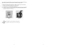
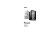
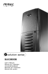
SLK1650-QE
User’s Manual
At Antec, we continually refine and improve our products to ensure the highest
quality. So it's possible that your new case may differ slightly from the descriptions
in this manual. This isn't a problem; it's simply an improvement. As of the date of
publication, all features, descriptions, and illustrations in this manual are correct.
Please consult your motherboard manual for specific mounting instructions and
troubleshooting.
1.
2.
Disclaimer
This manual is intended only as a guide for Antec's Computer Enclosures. For more comprehensive
instructions on installing your motherboard and peripherals, please refer to the user's manuals which
come with your components and drives.
3.
SLK1650-QE – Mini Tower Case
Your new case features a whisper-quiet 350 Watt SmartPower power supply,
with a main power switch. Make sure you turn the switch to the ON ( I )
position before you boot up your computer for the first time. Normally, you
won't need to switch to the OFF (O) position, since the power supply includes a
soft on/off feature. This lets you turn your computer on and off by using the
soft switch on your computer case. If your computer crashes and you can't
shut it down using the soft switch, you can switch the main power to the OFF
(O) position.
Applies only to models designed for sale in the European Union:
Solution Series Power Supply models designed for the EU include Power Factor
Correction (PFC) circuitry in accord with European standard regulation code
EN61000-3-2. By altering the input current wave shape, PFC improves the
power factor of the power supply. This results in increased energy efficiency,
reduced heat loss, prolonged life for power distribution and consumption
equipment, and improved output voltage stability.
Setting Up
1. Place the case upright on a flat, stable surface. The power supply fan
(at the back) should be facing you.
Note (not applicable to models designed for the European Union): Before
installation, check the red voltage switch setting on the power supply. It
should match your local voltage (115V for North America, Japan, etc. and
230V for Europe and many other countries). If it doesn't match, please
change the setting. If you don't, you could damage your equipment and
void your warranty.
2. Remove the two thumbscrews which fasten the top cover. These are the
only screws you need to remove to open the case. Set these screws aside
and keep them separate from the other screws.
3. Slide the top panel toward the rear of the case and lift it up to remove.
4. At the top of the each side panel, in front of the power supply, there is a
4" wide tab. Lift this tab and pull the side panel out to remove.
5. Inside the case you should see the power supply, some wiring (LED's, etc.),
an installed I/O panel, a power cord and a plastic bag containing more hard
ware (screws, brass standoff, plastic stands, etc.).
Installing the Motherboard
This manual is not designed to cover CPU, RAM, or expansion card installation.
1
4.
5.
6.
7.
Lay the case down, with the open side facing up. The drive cages and
power supply should be visible.
Make sure you have the correct I/O panel for your motherboard. If the
panel provided with the case isn't suitable, please contact your motherboard
manufacturer for the correct I/O panel.
Line up your motherboard with the standoff holes, and remember which
holes are lined up. Not all motherboards will match with all of the provided
holes; this is normal, and won't affect functionality. (In other words, there
will likely be extra holes.)
Remove your motherboard by lifting it up.
Screw the brass standoffs into the threaded holes that line up with your
motherboard. Do not overtighten the standoffs. Some standoffs may be
pre-installed for your convenience.
Place your motherboard on the brass standoffs.
Screw in your motherboard to the standoffs with the provided Phillips-head
screws. Your motherboard is now installed.
Connecting the Power and LED
The Antec SmartPower power supply is an ATX12V form factor power supply
with a single 20-pin Main Power Connector, a 6-pin AUX Power Connector, and
a 4-pin +12V Power Connector for the motherboard. It also includes 2 SATA
connectors, five to seven 4-pin Peripheral Power Connectors and one to two
4-pin Floppy Drive Power Connectors for your drives. It is backwards compatible
to previous ATX form factor power supplies. If your motherboard does not
support the AUX Power Connector or the +12V Power Connector, you can still
use this power supply.
The power supply is also equipped with a 3-pin fan signal connector. Connect it
to one of the fan connectors on your motherboard. You may monitor the speed
of the rear power supply fan through your motherboard BIOS or through the
monitoring software that's supplied with your motherboard. Note: At low
temperatures, the fan may run as slow as 1200 RPM. At these speeds, some
motherboards may not properly detect the fan speed and may generate false
warnings of fan failure. To ensure proper monitoring of the fan, please check
your motherboard manual.
1.
2.
3.
4.
5.
Connect the 20-pin ATX power connector (and AUX or +12V connectors
if appropriate) to your motherboard.
Connect the Reset switch (labeled RESET SW) to your motherboard at the
RST connector. Make sure the label always faces the front of the case.
Connect the Power Switch (labeled POWER SW) to the PWR connector on
your motherboard.
You'll find the Speaker connector (labeled SPEAKER) behind the PWR
connector.
The Power LED, Hard Drive LED, LED I & LED II connectors all share a
single ribbon cable. Attach the Power LED (labeled POWER) and HDD LED
connectors to the appropriate headers on your motherboard. You can use
the LED I and LED II connectors as you see fit: as SCSI LED, Message LED,
2
etc. or any other function supported by your motherboard, expansion cards, and
peripherals.
Connecting the USB ports
You'll find two 5-pin internal USB connectors (on separate cable sets) attached
to the front USB connectors. Here's how to connect the internal USB connector
to your motherboard headers:
1.
2.
Check the USB pin layout in your motherboard user manual and make sure
it follows this standard pin out:
Pin 1: USB Power - may also be labeled +5V
Pin 2: Negative Signal - may also be labeled P-, D-, USB0-, etc.
Pin 3: Positive Signal - may also be labeled P+, D+, USB0+, etc.
Pin 4: Ground
Pin 5: Ground (sometimes this pin is missing)
Note: Your motherboard's USB pin layout may differ from this common
standard. If you're unsure of your motherboard's layout, please contact
technical support at your motherboard's manufacturer.
Connect the 5-pin USB connector so that the red wire is on Pin 1 (Power,
or +5V). The second header may be reversed (Power pin at the opposite
end of the row) so be careful when you plug in both connectors.
1
Motherboard Pin Layout
2
Pin Signal names
9
10
Pin
Signal names
2
USB Power 2
1
USB Power 1
3
Negative Signal 1
4
Negative Signal 2
5
Positive Signal 1
6
Positive Signal 2
7
Ground 1
8
Ground 2
9
Key (No Connection)
10
Empty Pin
Installing 3.5" Devices
There is one 3.5" drive cage inside the case. The upper portion can hold 2
external 3.5" drives, and the lower portion can hold 3 internal 3.5" drives.
1.
2.
3.
6.
7.
Mount your external 3.5" drives into the top two drive bays. Load the
drives from the back, lining them up to the front of the drive cage.
Use one hand to support the drive, and fasten the drive to the cage with
the screws provided.
Mount your hard drive or other internal 3.5" device into the drive cage by
threading the special screws through the rubber grommets. Don't overtighten the screws, since that could decrease the grommets' ability to
reduce vibration and noise.
Find a small 4-pin connector on the power supply and connect it to the
male 4-pin connector on the floppy drive.
Connect a 4-pin large connector from the power supply to the male 4-pin
connector on each of the other devices.
3
Installing 5.25" Devices
1. If you look at the 5.25" drive bays from the rear of the case, you'll see
some metal grilles covering those bays. Carefully push a screwdriver
through the metal grille, and gently remove the plastic drive bay cover by
pushing outwards.
2. Use your hands to twist the metal plate back and forth until it breaks off.
Note: Don't break off the metal grilles covering the drive bays that you
don't intend to use now. Be careful of the newly exposed metal where the
grille was attached, as these areas are likely to be sharp.
3. Using the screws provided, fasten your 5.25" device into the drive bay.
4. Repeat the same procedure for other devices.
5. Connect a 4-pin large connector from the power supply to the male 4-pin
connector on each of the devices.
Connecting the Data Cables
After you've connected the devices to the power supply, you need to connect
data cables between the devices and the motherboard. To achieve the best
data-transfer and cooling performance, we recommend using premium rounded
cables such as Antec Cobra Cables.
The cables that are included with your drives should have a red strip on one
side indicating pin number 1. If you use these cables, make sure that the red
strip is on pin 1, usually toward the power connector.
Installing the Fan
We've included one low-speed 120mm exhaust fan with this case. This (rear)
fan is mounted with a vibration-absorbing NoiseKiller™ kit, which will allow your
computer to run extremely quietly. In the front of the case, you'll also find a
mount for an optional 80mm intake fan.
The rear fan is installed so that the air blows out of the case. Find a large 4-pin
peripheral connector on the power supply and connect it to the male 4-pin
connector on the fan.
The front fan (optional) should be installed so that the air is blowing into the
case from the front. To install it:
1.
2.
3.
4.
Release the fan cage by squeezing the tabs.
Put the fan in the cage and push it into place until it snaps tight.
Snap the fan cage back into place.
Connect a large 4-pin peripheral connector from the power supply to the
male 4-pin connector on the front fan.
Chassis Air Guide
Your new case includes a chassis air guide, which provides cooling air directly
to the CPU. The air guide consists of three parts: an upper duct, flange, and
lower duct. If you prefer, you can adjust the distance between the lower duct
and your CPU, for maximum cooling efficiency.
4
You could also install an 80mm intake fan between the air guide and the case's
side panel. This will further improve your system's cooling airflow.
To
1.
2.
3.
4.
mount the optional fan between the chassis air guide and the side panel:
Remove the chassis air guide from the side panel.
Attach the fan to the side panel (see Figure 1).
Using the fan screws, lock the flange of the air guide to the fan (see Figure 2).
Connect a large 4-pin peripheral connector from the power supply to the
male 4-pin connector on the fan.
Figure 2
Figure 1
Antec Quality 3-Year parts and labor warranty (AQ3)
See details at: http://www.antec-inc.com/warranty.html
5
6
SLK1650-QE
Quiet Black Mid Tower Case
1
2
4
3
Drawing
Number
17
Description
16
1
Top Panel
15
2
Rear 120mm Fan blowhole
14
3
Left Side Panel
4
Front Bezel
5
5.25” Drive Bay Cover
6
3.5” Drive Bay Cover
7
Front USB Ports
8
Plastic Feet
9
Lower 3.5” Drive Cage
10
Upper 3.5” Drive Cage
11
Expansion Slot Cover
12
Universal I/O Panel
13
Right Side Panel
14
Upper Duct
15
16
Flange
17
Thumbscrew
13
4A
522
A60
A&
B&
M
A&
B&
M
5
A&
B
12
6
7
11
10
9
8
Lower duct
Antec, Inc.
47900 Fremont Blvd.
Fremont, CA 94538
tel: 510-770-1200
fax: 510-770-1288
Antec Europe B.V.
Sydneystraat 33
3047 BP Rotterdam
The Netherlands
tel: +31 (10) 462-2060
fax: +31 (10) 437-1752
Technical Support:
US & Canada
1-800-22ANTEC
[email protected]
Europe
+31 (10) 462-2060
[email protected]
www.antec-inc.com
©
Copyright 2004 Antec, Inc. All rights reserved.
All trademarks are the property of their respective owners.
Reproduction in whole or in part without written permission is prohibited.
Printed in China.
Version 1.0.1 03/25/2004