1
SLK3800B
User’s Manual
Manuel de l’utilisateur
Anwenderhandbuch
Manuale per l’operatore
Manual del usuario
At Antec, we continually refine and improve our products to ensure the highest
quality. So it's possible that your new case may differ slightly from the
descriptions in this manual. This isn't a problem; it's simply an improvement.
As of the date of publication, all features, descriptions, and illustrations in this
manual are correct.
Disclaimer
This manual is intended only as a guide for Antec's Computer Enclosures. For more comprehensive
instructions on installing your motherboard and peripherals, please refer to the user's manuals which
come with your components and drives.
SLK3800B – Black Super Mid Tower Case
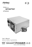
Your new case features a quiet 400 Watt SmartPower2.0 power supply, with a
main power switch. Make sure you turn the switch to the ON ( I ) position
before you boot up your computer for the first time. Normally, you won't need
to switch to the OFF (O) position, since the power supply includes a soft on/off
feature. This lets you turn your computer on and off by using the soft switch
on your computer case. If your computer crashes and you can't shut it down
using the soft switch, you can switch the main power to the OFF (O) position.
Note [Applies only to models designed for sale in the European Union:
SmartPower models designed for the EU include Power Factor Correction (PFC)
circuitry in accord with European standard regulation code EN61000-3-2. By
altering the input current wave shape, PFC improves the power factor of the
power supply. This results in increased energy efficiency, reduced heat loss,
prolonged life for power distribution and consumption equipment, and improved
output voltage stability.]
Setting Up
1. Place the case upright on a flat, stable surface. The power supply fan
(at the back of the case) should be facing you.
Note (not applicable to models designed for the European Union): Before
installation, check the red voltage switch setting on the power supply. It
should match your local voltage (115V for North America, Japan, etc. and
230V for Europe and many other countries). If it doesn't match, please
change the setting. If you don't, you could damage your equipment and
void your warranty.
2. Completely loosen the two thumbscrews that secure the right side panel.
(Note: they remain attached to the panel so you won't easily lose them.)
3. There are two latches on the side panel. Press the releases on each latch.
The latches will pop up partially. Disengage the latches by pushing them
fully out to the 90-degree position, and remove the panel by swinging it out.
4. Inside the case you should see the power supply, some wiring with marked
connectors (USB, PWR etc.), an installed I/O panel and a power cord. You
will also find an expansion slot protective cover mounted above the
expansion slots.
5. Place the case with the front bezel facing you and press the release tabs
on the bottom of the bezel to remove the front bezel. Set the bezel aside in
a safe place.
2
Installing the Motherboard
This manual does not cover CPU, RAM, or expansion card installation. Please
consult your motherboard manual for specific mounting instructions and
troubleshooting.
1.
2.
3.
4.
5.
6.
7.
Lay the case down, with the open side facing up. The drive cages and
power supply should be visible.
Make sure you have the correct I/O panel for your motherboard. If the
panel provided with the case isn't suitable, please contact your motherboard manufacturer for the correct I/O panel.
Line up your motherboard with the standoff holes, and remember which
holes are lined up. Not all motherboards will match with all of the provided
holes; this is normal, and won't affect functionality. (In other words, there
will likely be extra holes.)
Remove your motherboard by lifting it up.
Screw the brass standoffs into the threaded holes that line up with your
motherboard. Do not overtighten the standoffs. Some standoffs may be
pre-installed for your convenience.
Place your motherboard on the brass standoffs.
Screw in your motherboard to the standoffs with the provided Phillips-head
screws. Your motherboard is now installed.
Connecting the Power and LED
The power supply conforms to the latest ATX12V Version 2.0 standard. It is
also backwards-compatible with previous ATX form factor power supplies.
Before you connect the power supply to any of your devices, please consult the
appropriate user manuals for your motherboard and other peripherals.
The power supply is also equipped with a 3-pin fan signal connector. Connect
it to one of the fan connectors on your motherboard. You may monitor the
speed of the rear power supply fan through your motherboard BIOS or through
the monitoring software that's supplied with your motherboard. Note: At low
temperatures, the fan may run as slow as 950RPM. At these speeds, some
motherboards may not properly detect the fan speed and may generate false
warnings of fan failure. To ensure proper monitoring of the fan, please check
your motherboard manual.
1.
2.
3.
4.
5.
6.
Picture 2
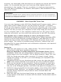
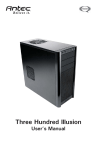
Connect the Main Power Connector and
Picture 1
the 4-pin +12V connector to your
motherboard as needed. If your
motherboard uses a 20-pin connector;
detach the 4-pin attachment on the 24-pin
power connector (see pictures 1 and 2).
For 24-pin
For 20-pin
Connect the Reset switch (labeled RESET
motherboards
motherboards
SW) to your motherboard at the RST
connector. Make sure the label always faces the front of the case.
Power LED (labeled POWER LED) connector is located behind the Reset connector.
Power Switch (labeled POWER SW) connects to the PWR connector on
the motherboard.
Speaker (labeled SPEAKER) connector is behind the PWR connector.
Hard Drive LED (labeled H.D.D. LED) connects to the IDE connector.
3
7.
LED I, LED II connectors: This case comes with two extra LEDs, marked
LED I, LED II. You may use these LED for various purchases such as SCSI
LED, Message LED, etc.
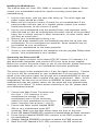
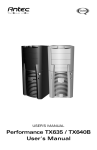
Connecting the USB Ports
You will find a single 10-pin connector on a cable attached to the front USB
ports. This is an Intel standard connector, which is keyed so that it can't be
accidentally reversed (as long as it's connected to an Intel-standard motherboard header). Connect the 10-pin connector to your motherboard headers so
that the blocked pin fits over the missing header pin.
Note: Please check your motherboard manual for your USB header pin layout
and make sure it matches the attached table. If it does not match this Intel
standard, please call Antec customer service at (800) 22ANTEC (North America)
or +31 0 (10) 462-2060 (Europe) to buy a USB adapter. This adapter will
allow you to connect the front USB to your motherboard on a pin-by-pin basis.
1
Motherboard Pin Layout
2
Pin Signal names
9
10
Pin
Signal names
1
USB Power 1
2
USB Power 2
3
Negative Signal 1
4
Negative Signal 2
5
Positive Signal 1
6
Positive Signal 2
7
Ground 1
8
Ground 2
9
Key (No Connection)
10
Empty Pin
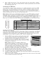
Installing 5.25" Devices
Your new case features four 5.25" drive bays. Each is covered by a ventilated
metal cover and an EMI Contact plate as one contiguous assembly. To make
installation easier and quicker, we've prepared the top drive bay without the
metal plate. If you'd like to install a 5.25" drive in another bay:
1.
2.
3.
4.
5.
6.
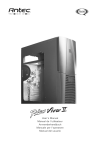
7.
Find the EMI Contact plate covering the lower half
of your chosen drive bay. Then bend it 90 degrees
inwards to form a drive support. (See Photo 1).
Carefully twist the assembly that covers the upper
half of your chosen drive bay back and forth. When
it breaks off, remove it.
Note: Please watch your fingers. Where you
removed the assembly, you're likely to find sharp
metal. If you don't plan to use certain drive bays,
leave the metal cover assemblies in place. And if
Photo 1
you later decide to cover drive bays again, we've
included two EMI cover plates in the toolbox.
Mount two drive rails to the sides of your 5.25" device.
Slide the device into the drive bay until you hear a click.
To install more drives, simply repeat the same procedure.
Connect a large 4-pin connector from the power supply to the male 4-pin
connector on each device.
When you're done, carefully push the plastic drive bay covers off the bezel.
Then re-attach the bezel to the case.
4
Installing 3.5" Devices
There are two 3.5" drive cages inside the case. The upper one can hold 2
external 3.5" drives, and the lower one can hold 5 internal 3.5" drives.
1.
2.
3.
4.
5.
6.
7.
8.
Release the upper cage by pulling the quick-release lever and then the cage
towards the rear of the case.
Unscrew the thumbscrew at the bottom of the lower cage. To remove the
lower cage, press the release tab at the top of the lower cage and pull the
cage out of the opening towards yourself.
Note: Some other removable drive cages require you to pull the cage
towards the back of the case. This does NOT apply to the lower drive
cage.
Put both cages on a flat surface.
Note: If you want to install a 120mm fan at the front of the case, you
should do this before you re-install the lower drive cage. See the next
section ('Installing the Fan') for details.
Mount your floppy drives or other external devices in the upper cage.
Mount your hard drive or other internal 3.5" devices in the lower drive bays
with the special screws provided. Don't over-tighten. Over-tightening the
screws will harm the vibration and noise reducing ability of the rubber
grommets.
Slide and lock both drive cages back into the case. Secure the thumbscrew
at the bottom of the lower drive cage.
For each floppy drive you've installed, find a small 4-pin connector on the
power supply and connect it to the male 4-pin connector on the floppy drive.
For each hard drive or other internal 3.5" device you've installed, find a
peripheral connector on the power supply and connect it to the on the 3.5" device.
Cooling System
The TriCool fan
The case includes one 120mm TriCool fan installed in the rear. This fan has a
three-speed switch that lets you choose between quiet, performance, or maximum
cooling. See specifications below. The fan is installed so that the air is blowing
out of the case. Connect a large 4-pin connector from the power supply to the
male 4-pin connector on the fan.
Note: The minimum voltage to start the fan is 5V. We recommend our users to
set the fan speed to High if you choose to connect the fan to a fan control
device or to the Fan-Only connector found on some of Antec's power supplies.
A fan-controlled-device regulates the fan speed by varying the voltage to it. The
voltage may start as low as 4.5 V to 5V. Connecting a TriCool set on Medium
or Low to a fan-control device may result in the fan not being able to start. The
already lowered voltage from the fan control device will be further reduced by
the TriCool circuitry below 5V.
5
Specifications
Size:
120 x 120 x 25.4 mm
Rated Voltage:
DC 12V
Operating Voltage: 10.2V ~ 13.8V
Speed
Input
Air Flow
Current
Static
Pressure
Acoustical
Noise
Input
Power
High
2000 RPM
0.24A
(max.)
2.24m3 / min
(79 CFM)
2.54mm-H2O 30 dBA
(0.10inch-H2O)
2.88 W
Medium
1600 RPM
0.2A
1.59m3 / min
(56 CFM)
2.54mm-H2O 28 dBA
(0.06inch-H2O)
2.4 W
Low
1200 RPM
0.13A
1.1m3 / min
(39 CFM)
0.92mm-H2O 25 dBA
(0.04inch-H2O)
1.56 W
The front fan (optional) should be installed so that the air is blowing into the
case from the front. To install it:
1.
2.
Drop the fan into the cage and push it in until it snaps into place.
If you're using a 4-pin fan, connect a large 4-pin connector from the power
supply to the male 4-pin connector on the fan. If you're using a 3-pin fan,
connect the 3-pin connector to a motherboard fan header.
Chassis Air Guide
Your new case includes a chassis air guide and vents, for improved cooling of
your CPU and overall system. The air guide consists of three parts: an upper
duct, flange, and lower duct. If you prefer, you can adjust the distance between
the lower duct and your CPU for maximum cooling efficiency.
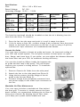
You can also install an 80mm intake fan between the
air guide and the case's side panel. This will further
improve your system's cooling airflow. To install the
optional fan:
1.
2.
3.
4.
Remove Chassis Air Guide from the side panel
Attach the fan to the side panel (see Photo 2).
Using the fan screws, lock the flange of the air
guide to the fan (see Photo 3).
Connect a large 4-pin peripheral connector from
the power supply to the make 4-pin connector on
the fan.
Photo 2
Washable Air Filter Maintenance
Your new case includes a washable air filter behind
the front grill. To access it, simply remove the front
bezel. Initially, we recommend washing the air filter at
least once a month. By keeping the air filter clean,
you'll help your system remain stable and cool.
6
Photo 3
Antec Quality 3-Year parts and labor warranty (AQ3)
See details at: http://www.antec.com/warranty.html
7
Antec, Inc.
47900 Fremont Blvd.
Fremont, CA 94538
tel: 510-770-1200
fax: 510-770-1288
Antec Europe B.V.
Sydneystraat 33
3047 BP Rotterdam
The Netherlands
tel: +31 (0) 10 462-2060
fax: +31 (0) 10 437-1752
Technical Support:
US & Canada
1-800-22ANTEC
[email protected]
Europe
+31 (0) 10 462-2060
[email protected]
www.antec.com
©
Copyright 2005 Antec, Inc. All rights reserved.
All trademarks are the property of their respective owners.
Reproduction in whole or in part without written permission is prohibited.
Printed in China.
Version 1.0.5 04/05/2005