1
WTI Part No.: 13602
Rev. A
PollCat NetLink-VIP
& NLJ-VIP
Pollable Call Accounting Terminals
User's Guide
Warnings and Cautions:
INSTALLATION INSTRUCTIONS
SECURE RACKING
If Secure Racked units are installed in a closed or multi-unit rack assembly, they may
require further evaluation by Certification Agencies. The following items must be
considered.
1.
The ambient within the rack may be greater than room ambient. Installation should
be such that the amount of air flow required for safe operation is not compromised.
The maximum temperature for the equipment in this environment is 45°C.
Consideration should be given to the maximum rated ambient.
2.
Installation should be such that a hazardous stability condition is not achieved due
to uneven loading.
INPUT SUPPLY
1.
Check nameplate ratings to assure there is no overloading of supply circuits that
could have an effect on overcurrent protection and supply wiring.
2.
When installing 48 VDC rated equipment, it must be installed only per the
following conditions:
A.
Connect the equipment to a 48 VDC supply source that is electrically isolated
from the alternating current source. The 48 VDC source is to be connected to
a 48 VDC SELV source.
B.
Input wiring to terminal block must be routed and secured in such a manner
that it is protected from damage and stress. Do not route wiring past sharp
edges or moving parts.
C.
A readily accessible disconnect device, with a 3 mm minimum contact gap,
shall be incorporated in the fixed wiring.
GROUNDING
Reliable earthing of this equipment must be maintained. Particular attention should
be given to supply connections when connecting to power strips, rather than direct
connections to the branch circuit.
No Serviceable Parts Inside;
Authorized Service Personnel Only
Do not attempt to repair or service this device yourself. Internal components must be
serviced by authorized personnel only.
• Shock Hazard - Do Not Enter
Disconnect Power
If any of the following events are noted, immediately disconnect the unit from the outlet
and contact qualified service personnel:
1.
If the power cord becomes frayed or damaged.
2.
If liquid has been spilled into the device or if the device has been exposed to rain or
water.
i
PollCat NetLink-VIP & PollCat NLJ-VIP - User’s Guide
FCC Part 15 Regulation
This equipment has been tested and found to comply with the limits for a Class A digital
device, pursuant to part 15 of the FCC Rules. These limits are designed to provide
reasonable protection against harmful interference when the equipment is operated
in a commercial environment. This equipment generates, uses, and can radiate radio
frequency energy and, if not installed and used in accordance with the instruction
manual, may cause harmful interference to radio communications. Operation of this
equipment in a residential area is likely to cause harmful interference in which case the
user will be required to correct the interference at his own expense.
This device complies with part 15 of the FCC Rules. Operation is subject to the
following two conditions: (1) This device may not cause harmful interference, and (2)
this device must accept any interference received, including interference that may cause
undesired operation
WARNING: Changes or modifications to this unit not expressly
approved by the party responsible for compliance could void the user’s
authority to operate the equipment
Industry Canada
This Class A digital apparatus complies with Canadian ICES-003.
Cet appareil numérique de la classe A est conforme à la norme NMB-003 du Canada.
This product meets the applicable Industry Canada technical specifications
The Ringer Equivalence Number is an indication of the maximum number of devices
allowed to be connected to a telephone interface. The termination on an interface may
consist of any combination of devices subject only to the requirement that the sum of the
RENs of all the devices does not exceed five
ii
Table of Contents
1.
Introduction . . . . . . . . . . . . . . . . . . . . . . . . . . . . . . . . . . . . . . . . . . . . . . . . . . . . . . . . 1-1
2.
Unit Description. . . . . . . . . . . . . . . . . . . . . . . . . . . . . . . . . . . . . . . . . . . . . . . . . . . . . 2-1
2.1. Front Panel Indicators . . . . . . . . . . . . . . . . . . . . . . . . . . . . . . . . . . . . . . . . . . . . 2-1
2.2. Back Panel. . . . . . . . . . . . . . . . . . . . . . . . . . . . . . . . . . . . . . . . . . . . . . . . . . . . . 2-2
3.
Quick Start Guide . . . . . . . . . . . . . . . . . . . . . . . . . . . . . . . . . . . . . . . . . . . . . . . . . . . 3-1
3.1. Hardware Installation . . . . . . . . . . . . . . . . . . . . . . . . . . . . . . . . . . . . . . . . . . . . 3-1
3.1.1. Apply Power to the VIP. . . . . . . . . . . . . . . . . . . . . . . . . . . . . . . . . . . . 3-1
3.1.2. Connect your PC to the VIP . . . . . . . . . . . . . . . . . . . . . . . . . . . . . . . . 3-1
3.2. Communicating with the VIP . . . . . . . . . . . . . . . . . . . . . . . . . . . . . . . . . . . . . . 3-2
3.2.1. Access via Console Port or Modem . . . . . . . . . . . . . . . . . . . . . . . . . . 3-2
3.2.2. Access via Network. . . . . . . . . . . . . . . . . . . . . . . . . . . . . . . . . . . . . . . 3-3
3.3. Connect your PBX to the VIP. . . . . . . . . . . . . . . . . . . . . . . . . . . . . . . . . . . . . . 3-4
4. Hardware Installation . . . . . . . . . . . . . . . . . . . . . . . . . . . . . . . . . . . . . . . . . . . . . . . . . 4-1
4.1. Connect the VIP to Power Supply. . . . . . . . . . . . . . . . . . . . . . . . . . . . . . . . . . . 4-1
4.1.1. AC Powered Units. . . . . . . . . . . . . . . . . . . . . . . . . . . . . . . . . . . . . . . . 4-1
4.1.2. DC Powered Units. . . . . . . . . . . . . . . . . . . . . . . . . . . . . . . . . . . . . . . . 4-2
4.2. Set-Up Switches . . . . . . . . . . . . . . . . . . . . . . . . . . . . . . . . . . . . . . . . . . . . . . . . 4-2
4.2.1. Default Baud Rate for Console Port (Sw1, Sw2, Sw3). . . . . . . . . . . . 4-2
4.2.2. Default Baud Rate for PBX Port A, PBX Port B,
and AUX Port (Sw4, Sw5) . . . . . . . . . . . . . . . . . . . . . . . . . . . . . . . . . 4-3
4.2.3. Dialback Security Mode (Sw6) . . . . . . . . . . . . . . . . . . . . . . . . . . . . . . 4-3
4.2.4. Console Port Password (Sw7) . . . . . . . . . . . . . . . . . . . . . . . . . . . . . . . 4-3
4.2.5. Power Up Default (Sw8) . . . . . . . . . . . . . . . . . . . . . . . . . . . . . . . . . . . 4-4
4.3. Reset to Defaults . . . . . . . . . . . . . . . . . . . . . . . . . . . . . . . . . . . . . . . . . . . . . . . . 4-5
4.4. Connecting Cables and Phone Line . . . . . . . . . . . . . . . . . . . . . . . . . . . . . . . . . 4-6
4.4.1. PBX Inputs A and B and AUX Port . . . . . . . . . . . . . . . . . . . . . . . . . . 4-7
4.4.2. Modem Port . . . . . . . . . . . . . . . . . . . . . . . . . . . . . . . . . . . . . . . . . . . . . 4-7
4.4.3. Console Port . . . . . . . . . . . . . . . . . . . . . . . . . . . . . . . . . . . . . . . . . . . . 4-7
4.4.4. Network Port . . . . . . . . . . . . . . . . . . . . . . . . . . . . . . . . . . . . . . . . . . . . 4-7
5.
Configuration . . . . . . . . . . . . . . . . . . . . . . . . . . . . . . . . . . . . . . . . . . . . . . . . . . . . . . . 5-1
5.1. Access to the Command Mode . . . . . . . . . . . . . . . . . . . . . . . . . . . . . . . . . . . . . 5-1
5.2. Menu System Conventions . . . . . . . . . . . . . . . . . . . . . . . . . . . . . . . . . . . . . . . . 5-3
5.2.1. Script Access to Menu Functions . . . . . . . . . . . . . . . . . . . . . . . . . . . . 5-3
5.3. Set System Parameters . . . . . . . . . . . . . . . . . . . . . . . . . . . . . . . . . . . . . . . . . . . 5-4
5.4. Port Configuration. . . . . . . . . . . . . . . . . . . . . . . . . . . . . . . . . . . . . . . . . . . . . . . 5-6
5.4.1. PBX Port A and PBX Port B . . . . . . . . . . . . . . . . . . . . . . . . . . . . . . . . 5-6
5.4.1.1. Field Suppression; The Lucent Switch Feature . . . . . . . . . . 5-8
5.4.2. Auxiliary Port Configuration. . . . . . . . . . . . . . . . . . . . . . . . . . . . . . . 5-10
5.4.3. Console Port Configuration . . . . . . . . . . . . . . . . . . . . . . . . . . . . . . . . 5-12
5.4.4. Modem Port Configuration . . . . . . . . . . . . . . . . . . . . . . . . . . . . . . . . 5-15
5.4.4.1. Dialback Security. . . . . . . . . . . . . . . . . . . . . . . . . . . . . . . . 5-19
5.4.5. Network Port Configuration . . . . . . . . . . . . . . . . . . . . . . . . . . . . . . . 5-20
5.4.5.1. The Email & Text Messaging Parameters Menu . . . . . . . . 5-23
5.4.5.2 The Ping Function . . . . . . . . . . . . . . . . . . . . . . . . . . . . . . . 5-25
5.4.6. PBX IP Port Configuration . . . . . . . . . . . . . . . . . . . . . . . . . . . . . . . . 5-26
6.
Menu System Description . . . . . . . . . . . . . . . . . . . . . . . . . . . . . . . . . . . . . . . . . . . . . 6-1
6.1. Firmware Tree . . . . . . . . . . . . . . . . . . . . . . . . . . . . . . . . . . . . . . . . . . . . . . . . . . 6-1
i
PollCat NetLink-VIP & PollCat NLJ-VIP - User’s Guide
7.
Status Screens . . . . . . . . . . . . . . . . . . . . . . . . . . . . . . . . . . . . . . . . . . . . . . . . . . . . . . 7-1
7.1. Buffer Status Screen . . . . . . . . . . . . . . . . . . . . . . . . . . . . . . . . . . . . . . . . . . . . . 7-2
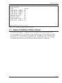
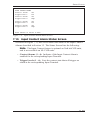
7.2. File List Screen . . . . . . . . . . . . . . . . . . . . . . . . . . . . . . . . . . . . . . . . . . . . . . . . . 7-3
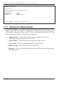
7.3. System Status Screen . . . . . . . . . . . . . . . . . . . . . . . . . . . . . . . . . . . . . . . . . . . . 7-4
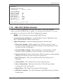
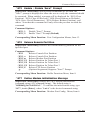
7.4. Scheduled Action Status Screens . . . . . . . . . . . . . . . . . . . . . . . . . . . . . . . . . . . 7-5
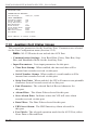
7.5. Dialback Security Status Screen . . . . . . . . . . . . . . . . . . . . . . . . . . . . . . . . . . . . 7-6
7.6. Data Filters & Alarms Status Screen. . . . . . . . . . . . . . . . . . . . . . . . . . . . . . . . . 7-7
7.7. Alarm Condition Status Screen. . . . . . . . . . . . . . . . . . . . . . . . . . . . . . . . . . . . . 7-9
7.8. PBX Inactivity Alarm Status Screens . . . . . . . . . . . . . . . . . . . . . . . . . . . . . . . 7-10
7.9. 80% Full Alarm Status Screen . . . . . . . . . . . . . . . . . . . . . . . . . . . . . . . . . . . . 7-12
7.10. Input Contact Alarm Status Screen . . . . . . . . . . . . . . . . . . . . . . . . . . . . . . . . . 7-13
7.11. Reason for Action Screen . . . . . . . . . . . . . . . . . . . . . . . . . . . . . . . . . . . . . . . . 7-14
7.12. PBX Port Status Screens . . . . . . . . . . . . . . . . . . . . . . . . . . . . . . . . . . . . . . . . . 7-15
7.13. Auxiliary Port Status Screen . . . . . . . . . . . . . . . . . . . . . . . . . . . . . . . . . . . . . . 7-16
7.14. Console Port Status Screen . . . . . . . . . . . . . . . . . . . . . . . . . . . . . . . . . . . . . . . 7-17
7.15. Modem Port Status Screen . . . . . . . . . . . . . . . . . . . . . . . . . . . . . . . . . . . . . . . 7-19
7.16. Network Port Status Screen . . . . . . . . . . . . . . . . . . . . . . . . . . . . . . . . . . . . . . 7-21
7.17. Network Status Screen . . . . . . . . . . . . . . . . . . . . . . . . . . . . . . . . . . . . . . . . . . 7-23
7.18. PBX IP Port Status . . . . . . . . . . . . . . . . . . . . . . . . . . . . . . . . . . . . . . . . . . . . . 7-24
7.19. Alarm Filter Clue Status Screens . . . . . . . . . . . . . . . . . . . . . . . . . . . . . . . . . . 7-25
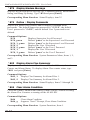
8.
The Data Filters . . . . . . . . . . . . . . . . . . . . . . . . . . . . . . . . . . . . . . . . . . . . . . . . . . . . . 8-1
8.1. The Data Filter Configuration Menus . . . . . . . . . . . . . . . . . . . . . . . . . . . . . . . . 8-1
8.2. Defining the Data Filter Format . . . . . . . . . . . . . . . . . . . . . . . . . . . . . . . . . . . . 8-2
8.3. Defining Data Filter Clues . . . . . . . . . . . . . . . . . . . . . . . . . . . . . . . . . . . . . . . . 8-4
8.4. Logical and Relational Operators . . . . . . . . . . . . . . . . . . . . . . . . . . . . . . . . . . . 8-6
8.4.1. Logical AND/OR Conditions . . . . . . . . . . . . . . . . . . . . . . . . . . . . . . . 8-7
8.4.1.1. Logical AND Conditions . . . . . . . . . . . . . . . . . . . . . . . . . . . 8-7
8.4.1.2. Logical OR Conditions . . . . . . . . . . . . . . . . . . . . . . . . . . . . 8-7
8.4.2. The "Contains String" Operator . . . . . . . . . . . . . . . . . . . . . . . . . . . . . 8-8
8.5. Real-Time Variables . . . . . . . . . . . . . . . . . . . . . . . . . . . . . . . . . . . . . . . . . . . . . 8-8
8.6. Assigning the Data Filter to a Port . . . . . . . . . . . . . . . . . . . . . . . . . . . . . . . . . . 8-9
8.7. Data Filter Definition Examples . . . . . . . . . . . . . . . . . . . . . . . . . . . . . . . . . . . . 8-9
9.
The Alarm Filters (Toll Fraud Detection) . . . . . . . . . . . . . . . . . . . . . . . . . . . . . . . . 9-1
9.1. Common Types of Suspect Phone Activity. . . . . . . . . . . . . . . . . . . . . . . . . . . . 9-1
9.2. The Alarm Configuration Menu . . . . . . . . . . . . . . . . . . . . . . . . . . . . . . . . . . . . 9-2
9.2.1. Default Alarm Filter Actions . . . . . . . . . . . . . . . . . . . . . . . . . . . . . . . . 9-2
9.3. The Alarm Filter Configuration Menus. . . . . . . . . . . . . . . . . . . . . . . . . . . . . . . 9-5
9.4. Defining the Alarm Filter Format . . . . . . . . . . . . . . . . . . . . . . . . . . . . . . . . . . . 9-6
9.5. Defining the Alarm Filter Clues . . . . . . . . . . . . . . . . . . . . . . . . . . . . . . . . . . . . 9-8
9.5.1. Alarm Clue Definition . . . . . . . . . . . . . . . . . . . . . . . . . . . . . . . . . . . . . 9-9
9.5.2. Editing and Deleting Clues . . . . . . . . . . . . . . . . . . . . . . . . . . . . . . . . 9-10
9.6. Logical and Relational Operators . . . . . . . . . . . . . . . . . . . . . . . . . . . . . . . . . . 9-11
9.6.1. Logical AND/OR Conditions . . . . . . . . . . . . . . . . . . . . . . . . . . . . . . 9-11
9.6.1.1. Logical AND Conditions . . . . . . . . . . . . . . . . . . . . . . . . . . 9-11
9.6.1.2. Logical OR Conditions . . . . . . . . . . . . . . . . . . . . . . . . . . . 9-12
9.6.2. The "Contains String" Operator . . . . . . . . . . . . . . . . . . . . . . . . . . . . 9-12
9.7. Real Time Variables . . . . . . . . . . . . . . . . . . . . . . . . . . . . . . . . . . . . . . . . . . . . 9-13
9.8. Assigning the Alarm Filter to a Port . . . . . . . . . . . . . . . . . . . . . . . . . . . . . . . . 9-14
9.9. Match Parameter Definition Examples . . . . . . . . . . . . . . . . . . . . . . . . . . . . . . 9-14
10. PBX Inactivity Alarms . . . . . . . . . . . . . . . . . . . . . . . . . . . . . . . . . . . . . . . . . . . . . . 10-1
10.1. Schedules and Timers . . . . . . . . . . . . . . . . . . . . . . . . . . . . . . . . . . . . . . . . . . . 10-1
10.2. Enabling the PBX Inactivity Alarm . . . . . . . . . . . . . . . . . . . . . . . . . . . . . . . . 10-2
ii
Table of Contents
11. The 80% Full Alarm . . . . . . . . . . . . . . . . . . . . . . . . . . . . . . . . . . . . . . . . . . . . . . . . 11-1
12. The Input Contact Alarms . . . . . . . . . . . . . . . . . . . . . . . . . . . . . . . . . . . . . . . . . . . 12-1
12.1. The Optional I/O Monitor . . . . . . . . . . . . . . . . . . . . . . . . . . . . . . . . . . . . . . . . 12-1
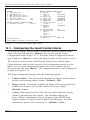
12.2. Configuring the Input Contact Alarm . . . . . . . . . . . . . . . . . . . . . . . . . . . . . . . 12-2
13. Alarm Actions . . . . . . . . . . . . . . . . . . . . . . . . . . . . . . . . . . . . . . . . . . . . . . . . . . . . . 13-1
13.1. Alarm Actions for Alarm Filter Clues. . . . . . . . . . . . . . . . . . . . . . . . . . . . . . . 13-2
13.2. Alarm Action Summary . . . . . . . . . . . . . . . . . . . . . . . . . . . . . . . . . . . . . . . . . 13-2
13.2.1. None (No Alarm Action) . . . . . . . . . . . . . . . . . . . . . . . . . . . . . . . . . . 13-2
13.2.2. Callout . . . . . . . . . . . . . . . . . . . . . . . . . . . . . . . . . . . . . . . . . . . . . . . . 13-3
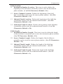
13.2.3. Alphanumeric Page . . . . . . . . . . . . . . . . . . . . . . . . . . . . . . . . . . . . . . 13-3
13.2.4. Numeric Page . . . . . . . . . . . . . . . . . . . . . . . . . . . . . . . . . . . . . . . . . . 13-4
13.2.5. SNMP Trap . . . . . . . . . . . . . . . . . . . . . . . . . . . . . . . . . . . . . . . . . . . . 13-4
13.2.6. Output Contact . . . . . . . . . . . . . . . . . . . . . . . . . . . . . . . . . . . . . . . . . 13-5
13.2.7. Console . . . . . . . . . . . . . . . . . . . . . . . . . . . . . . . . . . . . . . . . . . . . . . . 13-5
13.2.8. Email/Text Message . . . . . . . . . . . . . . . . . . . . . . . . . . . . . . . . . . . . . 13-6
13.3. The Auto Execute Function. . . . . . . . . . . . . . . . . . . . . . . . . . . . . . . . . . . . . . . 13-7
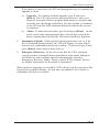
14. Scheduled Actions . . . . . . . . . . . . . . . . . . . . . . . . . . . . . . . . . . . . . . . . . . . . . . . . . . 14-1
15. Saving VIP Parameters . . . . . . . . . . . . . . . . . . . . . . . . . . . . . . . . . . . . . . . . . . . . . . 15-1
15.1. Saving Parameters to Flash Memory . . . . . . . . . . . . . . . . . . . . . . . . . . . . . . . 15-1
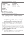
15.2. Saving and Restoring Parameters from an ASCII File . . . . . . . . . . . . . . . . . . 15-2
15.2.1. Saving Parameters to an ASCII File (Menu Driven Method) . . . . . 15-2
15.2.2. Saving Parameters to an ASCII File (Command Driven Method) . . 15-3
15.3. Configuring the VIP with Saved Parameters. . . . . . . . . . . . . . . . . . . . . . . . . . 15-5
16. Buffer Functions (Polling) . . . . . . . . . . . . . . . . . . . . . . . . . . . . . . . . . . . . . . . . . . . 16-1
16.1. Memory Partitions and Shared Data . . . . . . . . . . . . . . . . . . . . . . . . . . . . . . . . 16-1
16.1.1. Partitions and Files . . . . . . . . . . . . . . . . . . . . . . . . . . . . . . . . . . . . . . 16-2
16.1.2. Setting the Partition . . . . . . . . . . . . . . . . . . . . . . . . . . . . . . . . . . . . . . 16-4
16.1.3. Releasing the Partition. . . . . . . . . . . . . . . . . . . . . . . . . . . . . . . . . . . . 16-5
16.2. Menu Driven Data Release . . . . . . . . . . . . . . . . . . . . . . . . . . . . . . . . . . . . . . . 16-6
16.2.1. The Buffer Functions Menu . . . . . . . . . . . . . . . . . . . . . . . . . . . . . . . 16-6
16.2.2. Read Session Parameters. . . . . . . . . . . . . . . . . . . . . . . . . . . . . . . . . . 16-8
16.3. Command Driven Data Release . . . . . . . . . . . . . . . . . . . . . . . . . . . . . . . . . . . 16-9
16.3.1. Command ^B00 (Set/Release Partition) . . . . . . . . . . . . . . . . . . . . . 16-10
16.3.2. The ^B01 Command Line . . . . . . . . . . . . . . . . . . . . . . . . . . . . . . . . 16-11
16.3.3. Command ^B01 Examples . . . . . . . . . . . . . . . . . . . . . . . . . . . . . . . 16-12
16.3.4. Other Commands Used During Data Release . . . . . . . . . . . . . . . . . 16-13
16.4. Retrieving Data Using FTP Push . . . . . . . . . . . . . . . . . . . . . . . . . . . . . . . . . 16-14
16.4.1. File Names Created by FTP Push . . . . . . . . . . . . . . . . . . . . . . . . . . 16-19
16.4.2. FTP Push Start Time . . . . . . . . . . . . . . . . . . . . . . . . . . . . . . . . . . . . 16-21
16.5. The FTP Server Feature . . . . . . . . . . . . . . . . . . . . . . . . . . . . . . . . . . . . . . . . 16-22
16.5.1. Configuring the FTP Server Feature . . . . . . . . . . . . . . . . . . . . . . . . 16-22
16.5.2. Retrieving Data Using FTP Server. . . . . . . . . . . . . . . . . . . . . . . . . . 16-24
16.5.3. File Names for the FTP Server Function. . . . . . . . . . . . . . . . . . . . . 16-28
16.5.4. Commands Supported by FTP Server . . . . . . . . . . . . . . . . . . . . . . . 16-29
16.5.5. Response Messages Generated by the FTP Server Function . . . . . 16-30
16.6. The Auto Delete Function . . . . . . . . . . . . . . . . . . . . . . . . . . . . . . . . . . . . . . . 16-32
16.7. Zmodem Data Release Mode . . . . . . . . . . . . . . . . . . . . . . . . . . . . . . . . . . . . 16-32
iii
PollCat NetLink-VIP & PollCat NLJ-VIP - User’s Guide
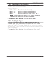
17. Other Menu Functions . . . . . . . . . . . . . . . . . . . . . . . . . . . . . . . . . . . . . . . . . . . . . . 17-1
17.1. System Functions . . . . . . . . . . . . . . . . . . . . . . . . . . . . . . . . . . . . . . . . . . . . . . 17-1
17.1.1. Security Level . . . . . . . . . . . . . . . . . . . . . . . . . . . . . . . . . . . . . . . . . . 17-1
17.1.2. Pass-Through Mode . . . . . . . . . . . . . . . . . . . . . . . . . . . . . . . . . . . . . 17-2
17.1.3. Monitor Mode . . . . . . . . . . . . . . . . . . . . . . . . . . . . . . . . . . . . . . . . . . 17-3
17.1.4. Clear Alarm Condition . . . . . . . . . . . . . . . . . . . . . . . . . . . . . . . . . . . 17-3
17.1.5. Clear Alarm Counters . . . . . . . . . . . . . . . . . . . . . . . . . . . . . . . . . . . . 17-4
17.1.6. Download Parameters . . . . . . . . . . . . . . . . . . . . . . . . . . . . . . . . . . . . 17-4
17.1.7. Audit Trail . . . . . . . . . . . . . . . . . . . . . . . . . . . . . . . . . . . . . . . . . . . . . 17-5
17.1.8. Upload Firmware. . . . . . . . . . . . . . . . . . . . . . . . . . . . . . . . . . . . . . . . 17-6
17.2. System Diagnostics . . . . . . . . . . . . . . . . . . . . . . . . . . . . . . . . . . . . . . . . . . . . . 17-8
17.2.1. Load and Test Memory . . . . . . . . . . . . . . . . . . . . . . . . . . . . . . . . . . . 17-8
17.2.2. Send Test Message . . . . . . . . . . . . . . . . . . . . . . . . . . . . . . . . . . . . . . 17-8
17.2.3. Test Pager . . . . . . . . . . . . . . . . . . . . . . . . . . . . . . . . . . . . . . . . . . . . . 17-9
17.2.4. Send Test SNMP Trap(s) . . . . . . . . . . . . . . . . . . . . . . . . . . . . . . . . . 17-10
17.3. Default Parameters . . . . . . . . . . . . . . . . . . . . . . . . . . . . . . . . . . . . . . . . . . . . 17-10
18. TCP Port Options . . . . . . . . . . . . . . . . . . . . . . . . . . . . . . . . . . . . . . . . . . . . . . . . . . 18-1
18.1. Standard Telnet Protocol & Raw Socket Mode . . . . . . . . . . . . . . . . . . . . . . . 18-1
18.2. Telnet Pass-Through . . . . . . . . . . . . . . . . . . . . . . . . . . . . . . . . . . . . . . . . . . . . 18-2
18.3. Real Time Mode . . . . . . . . . . . . . . . . . . . . . . . . . . . . . . . . . . . . . . . . . . . . . . . 18-3
18.4. Selective Read. . . . . . . . . . . . . . . . . . . . . . . . . . . . . . . . . . . . . . . . . . . . . . . . . 18-5
18.5. Multiple Telnet Connections . . . . . . . . . . . . . . . . . . . . . . . . . . . . . . . . . . . . . . 18-7
18.5.1. Conflicts with Other Command Ports . . . . . . . . . . . . . . . . . . . . . . . . 18-8
19 . Command Reference Guide . . . . . . . . . . . . . . . . . . . . . . . . . . . . . . . . . . . . . . . . . . 19-1
19.1. Command Mode Access . . . . . . . . . . . . . . . . . . . . . . . . . . . . . . . . . . . . . . . . . 19-1
19.2. Command Syntax . . . . . . . . . . . . . . . . . . . . . . . . . . . . . . . . . . . . . . . . . . . . . . 19-2
19.3. Command Help . . . . . . . . . . . . . . . . . . . . . . . . . . . . . . . . . . . . . . . . . . . . . . . . 19-3
19.4. Command Summary . . . . . . . . . . . . . . . . . . . . . . . . . . . . . . . . . . . . . . . . . . . . 19-4
Appendices
A.
Specifications . . . . . . . . . . . . . . . . . . . . . . . . . . . . . . . . . . . . . . . . . . . . . . . . . . . . Apx-1
A.1. NetLink-VIP Specifications . . . . . . . . . . . . . . . . . . . . . . . . . . . . . . . . . . . . .Apx-1
A.2. NLJ-VIP (NetLink Jr.-VIP) Specifications . . . . . . . . . . . . . . . . . . . . . . . . . .Apx-2
B.
Description of System Interfaces . . . . . . . . . . . . . . . . . . . . . . . . . . . . . . . . . . . . Apx-3
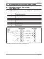
B.1. Input Ports (PBX A, PBX B, AUX) (DB9 Male; DTE) . . . . . . . . . . . . . . . .Apx-3
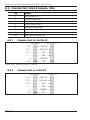
B.2. Console Port (DB-25 Female; DCE) . . . . . . . . . . . . . . . . . . . . . . . . . . . . . .Apx-4
B.2.1. Console Port to 25-Pin PC. . . . . . . . . . . . . . . . . . . . . . . . . . . . . . . .Apx-4
B.2.2. Console Port to 9-Pin PC. . . . . . . . . . . . . . . . . . . . . . . . . . . . . . . . .Apx-4
C.
Supervisor Functions and User Functions . . . . . . . . . . . . . . . . . . . . . . . . . . . . Apx-5
D.
Alarm Clue Definition Tips. . . . . . . . . . . . . . . . . . . . . . . . . . . . . . . . . . . . . . . . . Apx-7
E.
Customer Service. . . . . . . . . . . . . . . . . . . . . . . . . . . . . . . . . . . . . . . . . . . . . . . . Apx-10
G.
^Bxx Command Summary . . . . . . . . . . . . . . . . . . . . . . . . . . . . . . . . . . . . . . . . .Apx-11
Index . . . . . . . . . . . . . . . . . . . . . . . . . . . . . . . . . . . . . . . . . . . . . . . . . . . . . . . . . . . . . . Index-1
iv
Table of Contents
List of Figures
2.1.
2.2.
2.3.
3.1.
3.2.
4.1.
5.1.
5.2.
5.3.
5.4.
5.5.
5.6.
5.7.
5.8.
5.9.
5.10.
5.11.
5.12.
5.13.
7.1.
7.2.
7.3.
7.4.
7.5.
7.6.
7.7.
7.8.
7.9.
7.10.
7.11.
7.12.
7.13.
7.14.
7.15.
7.16.
7.17.
7.18.
7.19.
7.20.
8.1.
8.2.
8.3.
8.4.
8.5.
8.6.
8.7.
8.8.
9.1.
9.2.
Front Panel Indicators (NetLink-VIP Shown) . . . . . . . . . . . . . . . . . . . . . . . . . . . . . . 2-1
Back Panel (NetLink-VIP Model) . . . . . . . . . . . . . . . . . . . . . . . . . . . . . . . . . . . . . . 2-2
Back Panel (NLJ-VIP Model). . . . . . . . . . . . . . . . . . . . . . . . . . . . . . . . . . . . . . . . . . 2-2
The Main Menu . . . . . . . . . . . . . . . . . . . . . . . . . . . . . . . . . . . . . . . . . . . . . . . . . . . . . 3-2
The Network Parameters Menu . . . . . . . . . . . . . . . . . . . . . . . . . . . . . . . . . . . . . . . . . 3-3
DC Terminal Block Assembly . . . . . . . . . . . . . . . . . . . . . . . . . . . . . . . . . . . . . . . . . . 4-2
Main Menu. . . . . . . . . . . . . . . . . . . . . . . . . . . . . . . . . . . . . . . . . . . . . . . . . . . . . . . . . 5-1
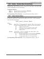
System Parameters Menu. . . . . . . . . . . . . . . . . . . . . . . . . . . . . . . . . . . . . . . . . . . . . . 5-4
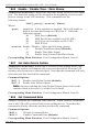
Port Selector Menu. . . . . . . . . . . . . . . . . . . . . . . . . . . . . . . . . . . . . . . . . . . . . . . . . . . 5-6
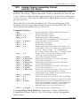
PBX Port Configuration Menu (Port A Shown). . . . . . . . . . . . . . . . . . . . . . . . . . . . . 5-7
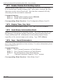
Field Suppression: The Lucent Switch Option . . . . . . . . . . . . . . . . . . . . . . . . . . . . . 5-8
Auxiliary Port Configuration Menu . . . . . . . . . . . . . . . . . . . . . . . . . . . . . . . . . . . . . 5-10
Console Port Configuration . . . . . . . . . . . . . . . . . . . . . . . . . . . . . . . . . . . . . . . . . . . 5-12
Modem Port Configuration Menu . . . . . . . . . . . . . . . . . . . . . . . . . . . . . . . . . . . . . . 5-15
Dialback Security Configuration Screen . . . . . . . . . . . . . . . . . . . . . . . . . . . . . . . . . 5-19
Network Configuration Menu . . . . . . . . . . . . . . . . . . . . . . . . . . . . . . . . . . . . . . . . . 5-20
The Send Email Configuration Menu . . . . . . . . . . . . . . . . . . . . . . . . . . . . . . . . . . . 5-23
The Ping Configuration Menu . . . . . . . . . . . . . . . . . . . . . . . . . . . . . . . . . . . . . . . . . 5-25
The PBX IP Port Configuration Menu . . . . . . . . . . . . . . . . . . . . . . . . . . . . . . . . . . . 5-26
Status Display Menu . . . . . . . . . . . . . . . . . . . . . . . . . . . . . . . . . . . . . . . . . . . . . . . . . 7-1
Buffer Status Screen. . . . . . . . . . . . . . . . . . . . . . . . . . . . . . . . . . . . . . . . . . . . . . . . . . 7-2
File List (Sample Values Shown). . . . . . . . . . . . . . . . . . . . . . . . . . . . . . . . . . . . . . . . 7-3
System Status Screen . . . . . . . . . . . . . . . . . . . . . . . . . . . . . . . . . . . . . . . . . . . . . . . . . 7-4
Scheduled Action Status Screen (Schedule 1 Shown) . . . . . . . . . . . . . . . . . . . . . . . . 7-5
Dialback Security Status Screen . . . . . . . . . . . . . . . . . . . . . . . . . . . . . . . . . . . . . . . . 7-6
Data Filters & Alarms Status Screen . . . . . . . . . . . . . . . . . . . . . . . . . . . . . . . . . . . . . 7-7
Alarm Condition Status Screen . . . . . . . . . . . . . . . . . . . . . . . . . . . . . . . . . . . . . . . . . 7-9
PBX Inactivity Alarm Status Screen (Alarm 1 Shown). . . . . . . . . . . . . . . . . . . . . . 7-10
80% Full Alarm Status Screen . . . . . . . . . . . . . . . . . . . . . . . . . . . . . . . . . . . . . . . . . 7-12
Input Contact Alarm Status Screen . . . . . . . . . . . . . . . . . . . . . . . . . . . . . . . . . . . . . 7-13
Reason for Action Screen. . . . . . . . . . . . . . . . . . . . . . . . . . . . . . . . . . . . . . . . . . . . . 7-14
PBX Port Status Screen (PBX Port A Shown). . . . . . . . . . . . . . . . . . . . . . . . . . . . . 7-15
Auxiliary Port Screen. . . . . . . . . . . . . . . . . . . . . . . . . . . . . . . . . . . . . . . . . . . . . . . . 7-16
Console Port Status Screen . . . . . . . . . . . . . . . . . . . . . . . . . . . . . . . . . . . . . . . . . . . 7-17
Modem Port Status Screen. . . . . . . . . . . . . . . . . . . . . . . . . . . . . . . . . . . . . . . . . . . . 7-19
Network Port Status Screen . . . . . . . . . . . . . . . . . . . . . . . . . . . . . . . . . . . . . . . . . . . 7-21
Network Status Screen . . . . . . . . . . . . . . . . . . . . . . . . . . . . . . . . . . . . . . . . . . . . . . . 7-23
PBX IP Port Status Screen . . . . . . . . . . . . . . . . . . . . . . . . . . . . . . . . . . . . . . . . . . . . 7-24
Alarm Filter Clue Status Screen (PBX Port A, Alarm Filter 1 Shown) . . . . . . . . . . 7-25
Data Filter Configuration Menu (Data Filter 1 Shown). . . . . . . . . . . . . . . . . . . . . . . 8-2
Data Filter Format Definition Menu . . . . . . . . . . . . . . . . . . . . . . . . . . . . . . . . . . . . . 8-3
Data Filter Format Definition Example . . . . . . . . . . . . . . . . . . . . . . . . . . . . . . . . . . . 8-4
The “Contains String” Operator Example . . . . . . . . . . . . . . . . . . . . . . . . . . . . . . . . . 8-8
Data Filter Example 1 . . . . . . . . . . . . . . . . . . . . . . . . . . . . . . . . . . . . . . . . . . . . . . . 8-10
Data Filter Example 2 . . . . . . . . . . . . . . . . . . . . . . . . . . . . . . . . . . . . . . . . . . . . . . . 8-11
Data Filter Example 3 . . . . . . . . . . . . . . . . . . . . . . . . . . . . . . . . . . . . . . . . . . . . . . . 8-11
Data Filter Example 4 . . . . . . . . . . . . . . . . . . . . . . . . . . . . . . . . . . . . . . . . . . . . . . . 8-12
Alarm Configuration Menu . . . . . . . . . . . . . . . . . . . . . . . . . . . . . . . . . . . . . . . . . . . . 9-2
Alarm Filter Configuration Menu (Alarm Filter 1 Shown) . . . . . . . . . . . . . . . . . . . . 9-5
v
PollCat NetLink-VIP & PollCat NLJ-VIP - User’s Guide
List of Figures (Continued)
9.3.
9.4.
9.5.
9.6.
9.7.
9.8.
9.9.
9.10.
10.1.
11.1.
12.1.
12.2.
14.1.
15.1.
16.1.
16.2.
16.3.
16.4.
16.5.
16.6.
16.7.
16.8.
16.9.
17.1.
17.2.
17.3.
19.1.
19.2.
B.1.
B.2.
B.3.
vi
Alarm Filter Format Definition Screen . . . . . . . . . . . . . . . . . . . . . . . . . . . . . . . . . . . 9-7
Alarm Filter Format Definition Example. . . . . . . . . . . . . . . . . . . . . . . . . . . . . . . . . . 9-7
Alarm Clue Definition Menu . . . . . . . . . . . . . . . . . . . . . . . . . . . . . . . . . . . . . . . . . . . 9-9
Alarm Filter Format; “Contains String” Example . . . . . . . . . . . . . . . . . . . . . . . . . . 9-12
Alarm Filter Format; Match Parameters Example 1 . . . . . . . . . . . . . . . . . . . . . . . . 9-15
Alarm Filter Format; Match Parameters Example 2 . . . . . . . . . . . . . . . . . . . . . . . . 9-16
Alarm Filter Format; Match Parameters Example 3 . . . . . . . . . . . . . . . . . . . . . . . . 9-17
Alarm Filter Format; Match Parameters Example 4 . . . . . . . . . . . . . . . . . . . . . . . . 9-18
PBX Inactivity Alarm Set-Up Menu (Alarm 1 Shown). . . . . . . . . . . . . . . . . . . . . . 10-3
The 80% Full Alarm Configuration Menu . . . . . . . . . . . . . . . . . . . . . . . . . . . . . . . . 11-2
The Alarm Configuration Menu. . . . . . . . . . . . . . . . . . . . . . . . . . . . . . . . . . . . . . . . 12-2
Input Contact Alarm Configuration Menu (Contact 1 Shown) . . . . . . . . . . . . . . . . 12-3
Scheduled Action Configuration Menu (Schedule 1 Shown) . . . . . . . . . . . . . . . . . 14-2
System Functions Menu. . . . . . . . . . . . . . . . . . . . . . . . . . . . . . . . . . . . . . . . . . . . . . 15-3
Data Partitions and Files (NetLink-VIP) . . . . . . . . . . . . . . . . . . . . . . . . . . . . . . . . . 16-2
Data Partitions and Files (NLJ-VIP) . . . . . . . . . . . . . . . . . . . . . . . . . . . . . . . . . . . . 16-2
Buffer Functions Menu . . . . . . . . . . . . . . . . . . . . . . . . . . . . . . . . . . . . . . . . . . . . . . 16-7
Set Read Session Parameters Menu . . . . . . . . . . . . . . . . . . . . . . . . . . . . . . . . . . . . . 16-8
FTP Push Configuration Menu. . . . . . . . . . . . . . . . . . . . . . . . . . . . . . . . . . . . . . . . 16-14
FTP Push File Names. . . . . . . . . . . . . . . . . . . . . . . . . . . . . . . . . . . . . . . . . . . . . . . 16-19
FTP Server Configuration Menu (Defaults Shown). . . . . . . . . . . . . . . . . . . . . . . . 16-22
FTP Server Example . . . . . . . . . . . . . . . . . . . . . . . . . . . . . . . . . . . . . . . . . . . . . . . 16-26
FTP Server File Names . . . . . . . . . . . . . . . . . . . . . . . . . . . . . . . . . . . . . . . . . . . . . 16-28
System Functions Menu. . . . . . . . . . . . . . . . . . . . . . . . . . . . . . . . . . . . . . . . . . . . . . 17-1
System Diagnostics Menu . . . . . . . . . . . . . . . . . . . . . . . . . . . . . . . . . . . . . . . . . . . . 17-8
Pager Test Menu. . . . . . . . . . . . . . . . . . . . . . . . . . . . . . . . . . . . . . . . . . . . . . . . . . . . 17-9
Command Help Screen . . . . . . . . . . . . . . . . . . . . . . . . . . . . . . . . . . . . . . . . . . . . . . 19-3
More Command Help. . . . . . . . . . . . . . . . . . . . . . . . . . . . . . . . . . . . . . . . . . . . . . . . 19-3
Data Input Ports (P{BX A, PBX B & AUX) . . . . . . . . . . . . . . . . . . . . . . . . . . . . .Apx-3
Console Port to 25-Pin PC . . . . . . . . . . . . . . . . . . . . . . . . . . . . . . . . . . . . . . . . . . .Apx-4
Console Port to 9 Pin PC . . . . . . . . . . . . . . . . . . . . . . . . . . . . . . . . . . . . . . . . . . . .Apx-4
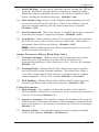
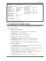
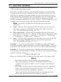
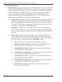
1. Introduction
The PollCat NetLink-VIP and PollCat NetLink Jr.-VIP (NLJ-VIP) Call
Accounting Terminals are highly reliable, PBX data recorders designed for
SMDR/CDR data collection and alarm monitoring. Collected call records
can be retrieved via TCP/IP network, via FTP client, via modem, or by a
local PC connected directly to the VIP unit.
In addition to storing call data, the VIP can also monitor call records for
suspicious phone activity or critical alarm conditions. When an alarm is
detected, the unit can immediately notify the proper personnel by pager,
modem, or SNMP trap. The VIP also provides secure access to connected
serial devices such as PBX maintenance ports or Console/AUX ports.
Network and Modem Access
All command functions, including data retrieval and unit configuration, can
be accessed via network, modem or local PC. When the VIP is installed in
a TCP/IP environment, Telnet is used to access the command mode. If outof-band access is required, you can also dial-up the VIP’s internal modem.
Stored data can be reliably retrieved using your terminal emulation
program, an FTP client or Zmodem protocol. Password protection and
dialback security prevent unauthorized access to control functions.
Nonvolatile Flash Memory
The VIP uses reliable, low-cost flash memory to store call records and
operating parameters. This eliminates the need to check and replace
depleted batteries. If power to the unit is lost or interrupted, stored data
can be retained indefinitely without worrying about low or dead batteries.
The VIP is available with 512 K to 64 Megabytes of internal memory. For
NetLink-VIP units only, if more memory is needed later, additional memory
modules can be easily snapped into place.
SNMP Traps
Alarm messages, memory full status, and a variety of other conditions can
be reported to your network manager via standard SNMP traps. SNMP
Traps can be used to provide notification when an alarm event occurs, or to
perform a wellness check at user selected time intervals.
1-1
PollCat NetLink-VIP & PollCat NLJ-VIP - User’s Guide
Up to Four PBX Inputs
The NetLink-VIP includes four separate data input ports; two PBX ports,
an Auxiliary Port and the PBX IP Port. This allows the unit to collect
data from four different sources. The Auxiliary Port can be connected to
a third PBX, or other data generating device, or used to pass commands
to a connected device such as WTI’s IPS-800 Internet Power Switch.
Communication parameters can be individually defined for each port.
When the unit is polled, data from the three ports can either be combined,
or read separately. Note that the NLJ-VIP includes only two input ports; the
PBX A Port and the PBX IP Port.
NetLink-VIP Units and NLJ-VIP Units
This User’s Guide discusses both NetLink-VIP units and NLJ-VIP
(NetLink Jr.-VIP) units. Throughout this User’s Guide, both units are
referred to as "VIP." The NetLink-VIP includes four input ports, and is also
available with expanded memory and the Input Contact option.
The NLJ-VIP includes two input ports and 512K of flash memory. All other
features function identically, except where noted.
Disclaimer on Toll Fraud
We do not guarantee that if you use the VIP, you will not become the
victim of toll fraud. We provide this device to assist you in minimizing
your exposure to such losses. By monitoring call records as they are
received, you can potentially catch calls that should not be made before
they escalate and cost you large sums of money. However, responding to
alarms and determining what is fraud and abuse are still up to you.
Western Telematic, Incorporated assumes no responsibility for any losses
due to improper use of this product.
Typographic Conventions
In this user’s guide, typefaces and characters are used as follows:
^ (e.g. ^B)
Indicates a key combination used to invoke a
command. For example, “^B” (Control B) indicates
that the [Ctrl] key and [B] key should be pressed
simultaneously.
COURIER FONT Indicates characters typed on the keyboard.
For example, ^B16 or ^B01.
[Bold Font]
1-2
Text set in bold face and enclosed in square brackets
indicates a specific key.
For example, [Enter] or [Esc].
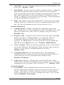
2.
Unit Description
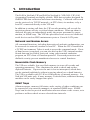
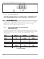
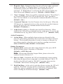
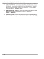
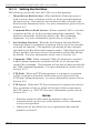
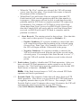
2.1.
Front Panel Indicators
POLLCAT
®
SYSTEM
MEMORY
MODEM
ON RDY ALM
>0% >25 >50 >75 FULL
OH DCD
1
2
NetLink-VIP
INPUT
CP
3
AUX
A
B
CDR Data Recorder
4
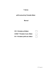
Figure 2.1: Front Panel Indicators (NetLink-VIP Shown)
➀ SYSTEM Indicators:
• ON: Lights when AC Power is applied to the unit.
• RDY: Flashes slowly to indicate the unit is operational.
• ALM: Lights when a Toll Fraud Alarm or PBX Inactivity Alarm is
triggered.
➁ MEMORY Indicators: A bank of five LEDs which light to indicate
approximate memory usage.
➂ MODEM Indicators: Two LEDs which indicate modem conditions
as follows:
• OH: (Off Hook) Lights when modem is off-hook.
• DCD: (Data Carrier Detect) Lights when carrier is detected.
➃ INPUT Indicators: A bank of four LEDs which indicate data
reception as follows:
• CP: Lights when commands are received via the Console Port.
• AUX: Lights when data is received via the AUX Port.
• A: Lights when data is received via PBX Port A.
• B: Lights when data is received via PBX Port B.
Note: The NLJ-VIP Model does not include the "B" or "AUX"
input ports or LED indicators for these ports.
2-1
PollCat NetLink-VIP & PollCat NLJ-VIP - User’s Guide
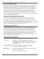
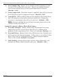
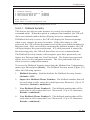
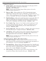
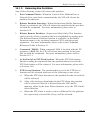
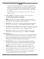
2.2.
Back Panel
7
6
8
I/O
MONITOR
OPTION
PBX INPUTS (DTE)
B
A
AUX
2
1
SETUP
(DCE)
4
3
RESET
5
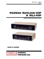
Figure 2.2: Back Panel (NetLink-VIP Model)
7
6
CONSOLE PORT
PBX INPUT
(DCE)
1
3
(DTE)
2
RESET
SETUP
5
4
Figure 2.3: Back Panel (NLJ-VIP Model)
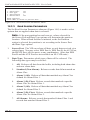
➀ AC Power Components: (AC Units Only) On/Off Switch and
Power Cable receptacle. DC units include a terminal block assembly
(Figure 4.1) in place of the power cable receptacle.
➁ PBX Input Connector(s): DB9 Connector(s) (DTE) used for
connection to your PBX SMDR Port(s).
Notes:
• NetLink-VIP Models include three PBX Input Connectors for
Port A, Port B and the AUX Port.
• NetLink-Jr.-VIP models include only one PBX Input Connector
and do not include the AUX Port.
• The AUX Port on the NetLink-VIP model can be connected to a
PBX, or used to pass commands to a connected device.
➂ Console Port: For connection to a local PC or terminal.
2-2
Unit Description
➃ Set-Up Switches: A bank of eight dip switches that are used to select
default options and communication settings.
➄ Reset Button: Used to reset the VIP to defaults and clear memory as
described in Section 4.3.
➅ Network Port: A 10Base-T connector with LED indicator(s). When
a network connection is present, the LINK indicator will light.
➆ Modem Port: For connection to a telecommunications line.
➇ I/O Monitor: (Not Shown - Option for NetLink-VIP Model
only) The optional I/O monitor allows the NetLink-VIP to monitor
externally supplied signals, and open or close contacts in response to
alarms or according to a user-defined schedule.
2-3
PollCat NetLink-VIP & PollCat NLJ-VIP - User’s Guide
2-4
3.
Quick Start Guide
This Quick Start Guide describes a simplified installation procedure for the
VIP hardware, which will allow you to communicate with the unit in order
to demonstrate basic features and check for proper operation.
Note that this Quick Start Guide does not provide a detailed description
of unit configuration, or discuss advanced operating features in detail. In
order to take full advantage of the complete range of features offered by the
unit, it is recommended to review the remainder of this User's Guide after
performing the Quick Start procedure.
3.1.
Hardware Installation
3.1.1. Apply Power to the VIP
Refer to the power rating nameplate on the VIP back panel, and then
connect the unit to an appropriate power source. The VIP features a
self-adjusting power supply that automatically adapts for 115 or 230 VAC
operation. Set the Master Power Switch on the VIP back panel to the ON
position; the front panel indicators should light. After a brief pause, the
RDY indicator should begin to flash, indicating that the unit is ready to
receive commands.
3.1.2. Connect your PC to the VIP
In order to configure the VIP unit, invoke commands or retrieve data,
you must first access the VIP command mode. The VIP offers three
different methods for activating the command mode; from a local PC that
is cable connected directly to the VIP Console Port, from a remote PC
that communicates with the VIP via modem, or from a remote PC that
communicates with the VIP via Ethernet connection. To connect your PC
to the VIP, proceed as follows:
• Control via Network: Connect your 10Base-T or 100Base-T network
interface to the VIP’s Network Port.
• Control via Console Port: Use the supplied null modem cable to
connect your PC COM port to the VIP’s Console Port.
• Control via Modem: Connect your phone line to the VIP’s
Modem Port.
Note: The VIP features a 10Base-T, half duplex Interface. When
connecting to a 100Base-T interface, most router switches will
autosense to determine if the device is 100Base-T or 10Base-T, and
then configure the network interface accordingly. If your router
switch does not autosense, the network interface port must be
manually set to 10Base-T, half duplex mode.
3-1
PollCat NetLink-VIP & PollCat NLJ-VIP - User’s Guide
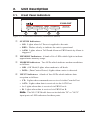
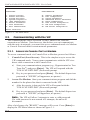
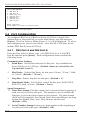
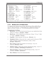
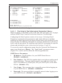
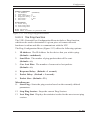
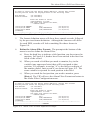
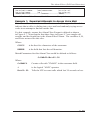
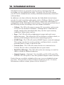
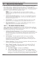
PollCat NetLink-VIP Main Menu:
Supervisor Mode
FUNCTIONS:
CONFIGURATION:
1.
2.
3.
4.
5.
6.
7.
8.
21.
22.
23.
24.
25.
26.
27.
28.
Status Displays
Buffer Functions
System Functions
System Diagnostics
^Bxx Command Help
Recall Parameters
Save Parameters
Exit Command Mode
Default Parameters
Port Configuration
System Parameters
Scheduled Action Parameters
Alarm Configuration
Data Filter Configuration
FTP Push Configuration
FTP Server Configuration
Enter selection ...
Figure 3.1: The Main Menu
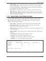
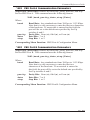
3.2.
Communicating with the VIP
The command mode can be accessed via the Console Port, network
connection or Modem. Note however, that before you can communicate
with the unit via network, you must first access command mode via Modem
or Console Port and define certain network parameters.
3.2.1. Access via Console Port or Modem
To access command mode via Console Port or Modem, proceed as follows:
1.
2.
Console Port (Local Access): This is the simplest way to access the
VIP command mode. Your system communicates with the VIP via a
direct cable connection to the Console Port.
a)
Start your communications program (e.g., Hyperterminal or Tera
Term Pro©) and press [Enter]. The VIP will respond with the
"POLLCAT-NETLINK" (Password) prompt.
b)
Key in your password and press [Enter]. The default Supervisor
password is "SUPER" (all uppercase, no quotes.)
Access Via Modem: Start your communications program and dial the
number for the phone line that is connected to the VIP.
a)
After the carrier is detected, the VIP will respond with the
"POLLCAT-NETLINK" (Password) prompt.
b)
Key in your password and press [Enter]. The default Supervisor
password is "SUPER" (all uppercase, no quotes.)
Note: The VIP will allow 5 attempts to enter a valid password.
If a valid password is not entered in 5 attempts, the unit will
disconnect.
After a brief pause, the "READY" message will be sent. Press [Enter] to
display the VIP Main Menu as shown in Figure 3.1.
3-2
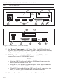
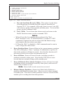
Quick Start Guide
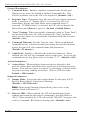
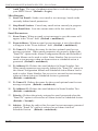
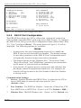
NETWORK PORT:
NIC Installed
COMMUNICATION SETTINGS
1. IP Address:
192.168.168.168
2. Subnet Mask:
255.255.255.0
3. Gateway Addr:
(undefined)
4. SNMP Manager 1: (undefined)
5. SNMP Manager 2: (undefined)
6. SNMP Community: public
7. Reset Network
8. Send MSS:
1460
9. Send Email
10. Ping
GENERAL PARAMETERS
11. Command Echo:
12. Response Type:
13. “Sure” Prompt:
14. CMD Timeout:
15. Audit Trail:
OUTPUT PARAMETERS
21. Output Mode:
22. Data on ^B01:
23. Hold End Data:
24. Line # Tag:
25. Send Compress:
26. Auto Delete:
ASCII Record
On
On
Off
Off
On
OUTPUT PARAMETERS (BINARY BLOCK)
27. Transmit Att:
3
28. Transmit Delay: 5 Secs
29. DLE Stuffing:
Off
On
Inhibit Menu
On
15 Mins
Off
ACTION PARAMETERS
16. Action Delay:
10 Secs
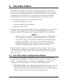
Enter selection, Press <ESC> to return to previous menu ...
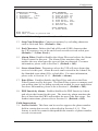
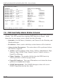
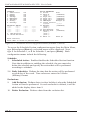
Figure 3.2: The Network Parameters Menu
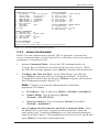
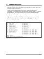
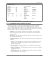
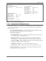
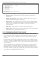
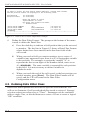
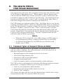
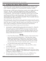
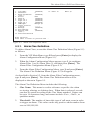
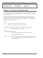
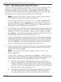
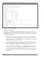
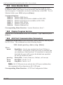
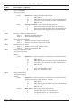
3.2.2. Access via Network
Before you can communicate with the VIP via network, you must first
access command mode via the Console Port or Modem, and set up network
parameters as described below.
1.
Access Command Mode: Access the VIP command mode via
Console Port or Modem as described in the previous section. When
the READY message appears, press [Enter] to display the main menu.
2.
Configure the Network Port: At the Main Menu, type 22 and
press [Enter] to display the Port Configuration Menu. At the Port
Configuration Menu, type 6 and press [Enter] to display the Network
Port Configuration menu (Figure 3.2):
Note: Consult your network administrator to determine
appropriate IP settings.
a)
3.
IP Address: Type 1 and press [Enter]. (Default = undefined.)
b)
Subnet Mask: Type 2 and press [Enter].
(Default = 255.255.255.0)
c)
Gateway Address: Type 3 and press [Enter] (If needed.)
(Default = undefined.)
Save Configuration Parameters and Exit Command Mode: Press
the [Esc] key several times to return to the main menu. From the
main menu, type 7 and press [Enter] to save the network parameters
entered in Step 2 above. After parameters have been saved, type 8 and
press [Enter] to exit from command mode.
3-3
PollCat NetLink-VIP & PollCat NLJ-VIP - User’s Guide
Access Command Mode via Network: Start your communications
program, and then key the VIP's IP address (defined in Step 2a) into
the address field. Select TCP Port 23 and then click OK or
press [Enter].
4.
a)
The "POLLCAT-NETLINK" (Password) prompt will be
displayed. The default Supervisor password is "SUPER" (all
uppercase, no quotes.)
b)
After a brief pause, the READY message will be displayed. Press
[Enter] to display the VIP main menu.
After you have successfully accessed command mode, you are then ready to
connect your PBX, configure the VIP unit and begin collecting data.
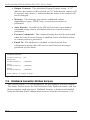
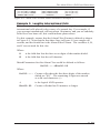
3.3.
Connect your PBX to the VIP
VIP units can collect data via cable from up to three local PBX units, and
can also collect data via network connection to a remote PBX unit. PollCat
NetLink-VIP units provide three PBX input ports for cable connection to
local PBX units, and NLJ-VIP units provide one PBX input port for cable
connection to a local PBX unit. Both VIP models include one PBX IP Input
port to allow data to be collected via network.
• Connecting a PBX to the VIP PBX Input Port: Use an appropriate
data cable to connect your PBX SMDR port to the VIP's PBX Input
Port. The serial PBX Input Port is a male, DB9 connector, wired in a
DTE configuration. The type of cable used will vary, depending on
the configuration of your PBX. For a description of VIP’s PBX Input
Port interface, please refer to Appendix B. Section 5.4.1 describes the
procedure for configuring the PBX input port(s).
• Connecting to a PBX via the Network Port (PBX-IP Port): Refer
to your PBX user’s guide, and then configure your RSP compatible
PBX to send data to the IP address for the VIP unit (defined in Step 2a
in Section 3.2.2.) In the default configuration, the VIP will receive
data via port number 9000. Section 5.4.6 describes the procedure for
configuring the PBX IP port.
This completes the Quick Start Guide for the VIP. Prior to placing the unit
into operation, it is recommended to refer to the remainder of this User's
Guide for complete installation, configuration and operation procedures.
If you have further questions regarding the VIP unit, please contact WTI
Customer Support as described in Appendix E.
3-4
4.
Hardware Installation
The hardware installation procedure includes the following steps:
1.
Connect the VIP unit to an appropriate power supply
(see Section 4.1).
2.
Use the Set-Up Switches to select default communication parameters
and options (see Section 4.2).
3.
Reset the VIP unit and clear the flash memory (see Section 4.3).
4.
Connect the data cables, network cable and telephone line
(see Section 4.4)
4.1.
Connect the VIP to Power Supply
Notes:
• When Switch 8 is UP (enable Power Up Default) and there is a
power interruption, baud rates will return to the default values
selected by Set-Up Switches 1 through 5.
• After configuring the unit with menu selected parameters, you
may wish to return Set-Up Switch 8 to the DOWN position. This
will cause the VIP to use menu selected parameters whenever the
unit is powered off and on.
CAUTION: This device should only be operated with the type of
power source indicated on the instrument nameplate. If you are
not sure of the type of power service available, please contact
your local power company.
4.1.1. AC Powered Units
Plug the power cable into the receptacle on the VIP back panel. The VIP
features a self-adjusting power supply that automatically adapts for 115 or
230 VAC. Place the AC Power Switch in the ON position to apply power,
the ON indicator will light and the RDY indicator will flash.
4-1
PollCat NetLink-VIP & PollCat NLJ-VIP - User’s Guide
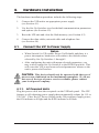
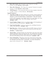
Figure 4.1: DC Terminal Block Assembly
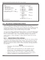
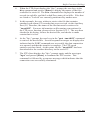
4.1.2. DC Powered Units
Attach the wires from your -48V DC power source (0.2 Amp Max.) to the
screw terminals, and then connect your ground line to the ground screw.
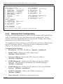
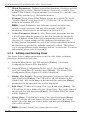
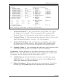
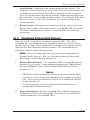
4.2.
Set-Up Switches
The Set-Up Switches select default communication parameters and enable
options such as Dialback Security, the Console Port Password, and Power
Up Default. Note that operating parameters are selected via the port
configuration menus as described in Section 5.4.
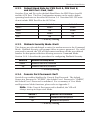
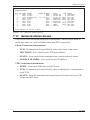
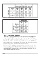
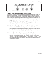
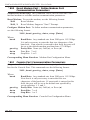
4.2.1. Default Baud Rate for Console Port
(Sw1, Sw2, Sw3)
Set-Up Switches One, Two, and Three select the default Baud Rate for the
Console Port. After the VIP is installed, the Port Configuration menu (Main
Menu, item 22) can be used to select the operating baud rate for the
Console Port.
Baud
Switch 1
Switch 2
Switch 3
9600 *
Down
Down
Down
38.4 K
Up
Down
Down
19.2 K
Down
Up
Down
4800
Up
Up
Down
2400
Down
Down
Up
1200
Up
Down
Up
600
Down
Up
Up
300
Up
Up
Up
* = Factory Setting
4-2
Hardware Installation
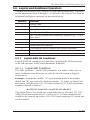
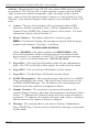
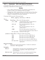
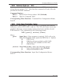
4.2.2. Default Baud Rate for PBX Port A, PBX Port B,
and AUX Port (Sw4, Sw5)
Switches Four and Five select default Baud Rates for PBX Ports A and B
and the AUX Port. The Port Configuration menus can be used to define
operating baud rates as described in Section 5.4. Note that NLJ-VIP units
do not include PBX Port B or the AUX Port.
Baud
Switch 4
Switch 5
Down
Down
4800
Up
Down
1200
Down
Up
300
Up
Up
9600 *
* = Factory Setting
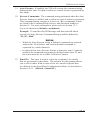
4.2.3. Dialback Security Mode (Sw6)
This feature provides additional security for modem access to the Command
Mode. Dialback Security will prompt callers to enter a password. If a valid
password is entered, the VIP will disconnect and then call the user-defined
number for that password before allowing access to Command Mode.
Section 5.4.4.1 describes the procedure for configuring Dialback Security.
Switch 6
Dialback Security Mode
Down *
Dialback Security Disabled
Up
Dialback Security Enabled
* = Factory Setting
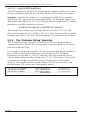
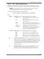
4.2.4. Console Port Password (Sw7)
Switch Seven enables/disables the Console Port Password. The default
Supervisor Password is "SUPER"; the default User 1 Password is "SMDR",
the default User 2 Password is undefined. For a summary of User Mode
and Supervisor Mode functions, please refer to Appendix C.
Note: If the Console Port password is disabled, the VIP will
always start up in Supervisor Mode.
Switch 7
Console Port Password
Down *
Password Not Required
Up
Password Required
* = Factory Setting
4-3
PollCat NetLink-VIP & PollCat NLJ-VIP - User’s Guide
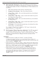
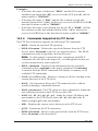
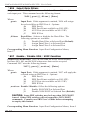
4.2.5. Power Up Default (Sw8)
The Power Up Default allows the user to reset communication parameters
to default settings without entering Command Mode.
Note: If you have changed Set-Up Switches 1 through 5, and you
wish to clear all menu selected parameters, Switch 8 should be set in
the UP position. This will allow default parameters selected by the
Set-Up Switches to take effect when the VIP is powered up.
When the Power Up Default is enabled, the VIP will reset the following
parameters after an interruption in power:
• Input Port Communication Parameters: The Baud rate for PBX
Ports A and B, and the AUX Port are set according to the Set-Up
Switches, rather than command selected parameters. All three ports
will be set at 7 bits, even parity, one stop bit. Note that NLJ-VIP units
do not include PBX Port B or the AUX Port.
• Console Port Communication Parameters: The Baud rate will be
set according to the Set-Up Switches. The Port will also be set for 8
bits, no parity, one stop bit.
• Modem Port Communication Parameters: The port will be set to
57600, 8 bits, no parity, one stop bit.
• Passwords: The Supervisor Password will default to "SUPER". The
User 1 Password will default to "SMDR". In the default state, the User
2 Password is not defined.
CAUTION: If Set-Up Switch 8 is UP (enable Power Up Default),
and there is a loss of power, port parameters will be set to the
default values selected by Set-Up Switches 1 - 6 rather than the
menu selected parameters.
If the Power Up Default is disabled (Sw8 = Down), when there is a power
interruption, The VIP will be configured according to the parameters
currently saved in flash memory.
Switch 8
Down *
Up
Power Up Default
Disabled (Use Saved Port Parameters)
Enabled (Re-Set to Switch-Selected Default Port
Parameters)
* = Factory Setting
4-4
Hardware Installation
4.3.
Reset to Defaults
This procedure will reset the VIP to the settings indicated by the Set-Up
switches, reset all menu selected parameters to factory defaults, and clear
memory.
When the unit is shipped from the factory, defaults are reset and the
memory is cleared. However, if the VIP has been previously installed, or
if you have changed switch settings, this procedure should be performed.
It is also recommended to reset the unit after installing additional memory
modules.
Notes:
• When this procedure is performed, all menu defined parameters
will be cleared. If the unit has already been configured,
parameter settings should be saved (as described in Section 15.2),
before beginning this procedure.
• If the VIP unit has the base 512K memory option (no SIMMs),
all stored data will be cleared. If the unit has collected data, it is
recommended to retrieve stored data (as described in Section 16)
before beginning this procedure.
To reset defaults and clear memory, proceed as follows:
1.
Press the Main Power Switch to the OFF position.
2.
Press and hold the Reset Button (located on the back panel) while
pressing the Main Power Switch to the ON position. Continue to hold
the Reset Button until the front panel indicators blink twice.
3.
After the indicators blink, release the Reset Button. After a brief
pause, the front panel indicators will blink three times. This indicates
that the reset procedure is complete.
4-5
PollCat NetLink-VIP & PollCat NLJ-VIP - User’s Guide
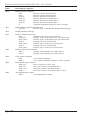
4.4.
Connecting Cables and Phone Line
Your cable layout should account for the following factors:
Command Mode Access: The VIP provides several methods for accessing
Command Mode
• Network Access: The VIP is managed via Ethernet. Note that initial
setup cannot be performed via network.
• Local Access: The VIP is managed by a local PC connected to the
Console Port.
• Remote Access: The VIP is managed by a remote PC that
communicates with the unit via modem.
• Multiple Access: The VIP can be managed via Network, Console
Port, or Modem.
Alarm Actions: The VIP offers several methods that can be used to notify
users when an alarm has been generated:
• SNMP Trap: An SNMP Trap is sent to a network management
station.
• Console Port Action: Alarms are sent to a local PC connected to the
Console Port.
• Modem or Pager: Alarms are sent to a remote PC or Pager.
• Email or Text Message: Alarms are sent via email or text message, to
up to two user-defined email addresses.
• Output Contacts: (Optional - Not Available on NLJ-VIP units.) The
Output Contacts can be opened or closed.
• Combination of Methods: Each alarm is directed to a different
target. The alarm configuration screens select notification methods for
each alarm.
The physical layout is determined by the Command Mode access method
and Alarm Actions required for your application. Determine which
method(s) will be used and install cables as outlined in the following
sections.
CAUTION: Prior to connecting data lines, make certain that
cables are compatible with The VIP. Please refer to the interface
descriptions in Appendix B.
4-6
Hardware Installation
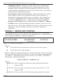
4.4.1. PBX Inputs A and B and AUX Port
The PBX Inputs and the AUX port are used for connection to your PBX
SMDR Port. The AUX Port can be connected to a third PBX, or used to
collect data from, or pass commands to other devices. For a description of
the port interface, please refer to Appendix B. Note that NLJ-VIP units do
not include PBX Port B or the AUX Port.
4.4.2. Modem Port
When an outside phone line is connected to the Modem Port, the VIP can
be managed and polled via modem. When an alarm is generated, the VIP
can also provide notification via modem or pager.
4.4.3. Console Port
The Console Port can be connected to a local PC, which is used to manage
and poll the VIP unit. Please refer to Appendix B for a description of the
Console Port interface.
4.4.4. Network Port
The Network Port allows connection to a TCP/IP network. When
installation is complete, the VIP unit can be managed and polled via
network. The VIP can also provide alarm notification via SNMP trap. Use
a straight wired 10Base-T cable.
Note: The VIP features a 10Base-T, half duplex network interface.
When connecting to a 100Base-T interface, most router switches
will autosense to determine if the device is 100Base-T or 10BaseT, and then configure the network interface accordingly. If your
router switch does not autosense, the network interface port must be
manually set to 10Base-T, half duplex mode.
4-7
PollCat NetLink-VIP & PollCat NLJ-VIP - User’s Guide
4-8
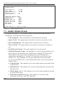
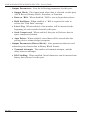
5. Configuration
When the VIP unit is shipped from the factory, options and parameters are
set to fit the requirements of most call accounting applications. In many
cases, if you do not choose to include the VIP's advanced features, no
further configuration is required.
However, if you do intend to use advanced features (such as the Data Filter
or Alarm Filter), or if your application requires parameters other than the
defaults described in this section, the unit must be properly configured.
This section describes how to reconfigure the VIP to meet the requirements
of almost any data collection application.
Although The VIP provides a substantial assortment of advanced program
features, it is not necessary to include all of these features in your system
configuration. You may wish to complete the basic set-up first, and then
add optional features as needed.
When configuring the unit, note that the Status Screens can be accessed via
item 1 in the Main Menu. This allows you to determine the current state
of any feature, and verify that parameters are correctly defined. For more
information on the Status Screens, please refer to Section 7.
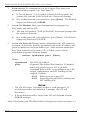
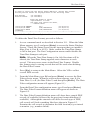
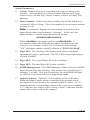
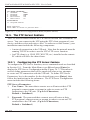
5.1. Access to the Command Mode
When the command mode is active, the unit will display a series of menus
used to select parameters, enable options, and retrieve stored data.
During initial configuration, command mode can only be accessed via the
Console Port or Modem Port. After network parameters have been defined,
you will also be able to access command mode via the Network Port. To
access command mode for initial configuration, proceed as follows:
PollCat NetLink-VIP Main Menu:
Supervisor Mode
FUNCTIONS:
CONFIGURATION:
1.
2.
3.
4.
5.
6.
7.
8.
21.
22.
23.
24.
25.
26.
27.
28.
Status Displays
Buffer Functions
System Functions
System Diagnostics
^Bxx Command Help
Recall Parameters
Save Parameters
Exit Command Mode
Default Parameters
Port Configuration
System Parameters
Scheduled Action Parameters
Alarm Configuration
Data Filter Configuration
FTP Push Configuration
FTP Server Configuration
Enter selection ...
Figure 5.1: Main Menu
5-1
PollCat NetLink-VIP & PollCat NLJ-VIP - User’s Guide
1.
2.
3.
Local Access: To communicate via the Console Port, start your
communications program (e.g. ProComm™).
a)
If Set-Up Switch 7 is UP (enable Console Port Password), the
system will send the "PollCat-NetLink" (Password) Prompt.
b)
Key in the password (case-sensitive), press [Enter]. The Default
Supervisor Password is SUPER.
Access Via Modem: Start your communications program (e.g.,
ProComm) and dial the VIP.
a)
The unit will send the "PollCat-NetLink" (Password) prompt after
the carrier is detected.
b)
Key in the password (case-sensitive), press [Enter]. The Default
Supervisor Password is SUPER.
Access via Network: During initial configuration, the VIP cannot be
accessed via Network, because parameters such as the IP address and
gateway mask have not been defined yet. After network parameters
have been defined (see Section 5.4.5), a Telnet session can be
established using the following format:
telnet ipaddress port [Enter]
Where:
ipaddress
port
The VIP's IP Address
(Optional) The desired Port Number. If omitted,
telnet will connect to port #23 by default;
Command Echo will be set according to the VIP's
current configuration, and $FF Stuffing will be
enabled. Options:
2001 Behaves same as port #23.
3001 Preconfigured with Echo enabled, and
$FF Stuffing Off.
Notes:
• The VIP will allow 3 attempts to enter a valid password. If
a valid password is not entered in 3 attempts, the VIP will
disconnect.
• If an invalid password is entered, the VIP will respond with the
ERROR message.
After a brief pause, the VIP Main Menu will appear as shown in Figure 5.1.
5-2
Configuration
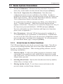
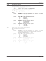
5.2. Menu System Conventions
1.
Access to Submenus: All menus are key activated. To access a
menu, key in the number for the desired item and press [Enter].
2.
User Level / Supervisor Level Functions: Note that most
configuration menus are not available in User Mode. In order to
perform the setup procedures described in this section, the Supervisor
Mode must be active. The top of the Main Menu indicates whether
User or Supervisor Mode is currently selected.
To switch from User Mode to Supervisor Mode, select Main Menu
Item 3 "System Functions". When the System Functions menu
appears, select Item 1 "Security Level", and select Supervisor. Key in
the Supervisor password (Default = SUPER) and press [Enter].
For more information on User functions and Supervisor functions,
please refer to Appendix C.
3.
Save Parameters: After the VIP has been properly configured, it
is recommended to save parameters to flash memory. If parameters
are not saved, the VIP will revert to the previous configuration when
power to the unit is switched off or interrupted. To save parameters,
go to the Main Menu, type 7 and press [Enter].
5.2.1. Script Access to Menu Functions
The VIP menu functions can also be accessed using scripts. This allows
you to create polling programs that select items from command menus
in order to change parameters. When writing polling software, use the
following conventions:
1.
Wait for Menu: To allow the polling program to determine when
a menu has been completely sent, search for the character(s) at the
end of the menu. For most menus, the last three characters will be an
ellipsis (three periods).
2.
Selecting Menu Items: Specify the desired menu item by number,
followed by a carriage return.
3.
Moving Up One Level: To exit from a menu and return to the
previous menu, send an Escape character.
5-3
PollCat NetLink-VIP & PollCat NLJ-VIP - User’s Guide
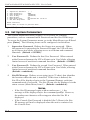
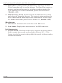
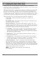
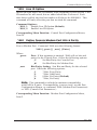
SYSTEM PARAMETERS:
1.
2.
3.
4.
5.
6.
7.
Supervisor Password:
User Password 1:
User Password 2:
Site ID Msg:
Wrap-Around:
Real-Time-Clock:
Alm Data Wrap-Arnd:
(...)
SMDR
(undefined)
(undefined)
Off
06/18/2004 Fri 16:39:05
Off
Enter selection,
Press <ESC> to return to previous menu ...
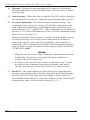
Figure 5.2: System Parameters Menu
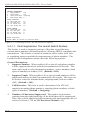
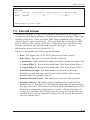
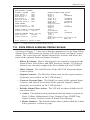
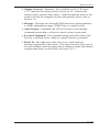
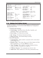
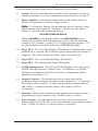
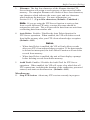
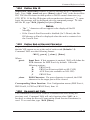
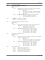
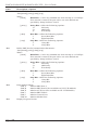
5.3. Set System Parameters
The System Parameters menu (Figure 5.2) is used to set common
parameters, such as command mode Passwords and the Site ID Message.
To access the System Parameters menu, go to the Main Menu, type 23 and
press [Enter]. The following items can be configured via this menu:
1.
Supervisor Password: Defines the Supervisor password. When
this password is entered at the Password Prompt, the VIP will start
up in Supervisor Mode, allowing access to all menu and command
functions. (Default = SUPER.)
2.
User Password 1: Defines the first User Password. When entered
at the Password prompt, the VIP will start up in User Mode, allowing
limited access to menu and command functions. (Default = SMDR.)
3.
User Password 2: Defines the second User Password. When entered
at the Password prompt, the VIP will start up in User Mode, allowing
limited access to menu and command functions.
(Default = undefined.)
4.
Site ID Message: Defines a text string (up to 32 char.) that identifies
the location where the unit is installed. If this item is defined, the
Site ID will be displayed prior to the Command Prompt, each time
command mode is accessed. The Site ID can also be displayed via the
status screens (Main Menu, Item 1). (Default = undefined.)
Notes:
• If the Site ID message begins with an underscore (_), the
message will be displayed after the command prompt. However,
the underscore character will not appear when the Site ID is
displayed.
• If the Console Port Password is disabled (Sw7=Down), the Site
ID message will not be displayed when the unit is contacted via
the Console Port.
5-4
Configuration
5.
Wrap-Around: If internal memory becomes full, the wrap-around
option allows new data to be written over older data, enabling the unit
to continually recycle its memory. While command mode is active,
new data will not overwrite older data in the current partition. Any
new data will be stored outside the top boundary. If memory is full,
no additional data will be stored while command mode is active.
(Default = On.)
Note: When Wrap-Around is enabled and memory becomes
full, there will be a noticeable delay while the unit clears old data
and writes new data to flash memory. During this period, the VIP
will delay response to additional commands until the wrap-around
process is complete. Note that newly received data will not be lost
during this delay.
6.
Real-Time Clock: Sets the VIP's internal clock and calendar. Since
time dependent features (e.g. Scheduled Actions, PBX Inactivity
Alarm) rely on the internal clock, it is important that the clock and
calendar are accurately set.
5.
Alarm Data Wrap-Around: This feature is identical to item 6 above,
except that the Alarm Data Wrap-Around only applies to data that
matched a user-defined Alarm Clue. For more information on Alarms
and Alarm Clues, please refer to Section 9. (Default = Off.)
5-5
PollCat NetLink-VIP & PollCat NLJ-VIP - User’s Guide
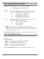
PORT CONFIGURATION:
1.
2.
3.
4.
5.
6.
7.
PBX Port A
PBX Port B
Auxiliary Port
Console Port
Modem Port
Network Port
PBX IP Port
Enter selection,
Press <ESC> to return to previous menu ...
Figure 5.3: Port Selector Menu
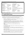
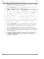
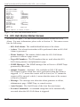
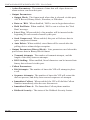
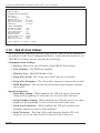
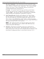
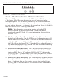
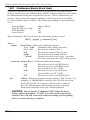
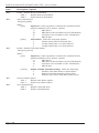
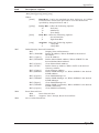
5.4. Port Configuration
To configure PBX Port A, PBX Port B, the AUX Port, Console Port,
Modem Port or Network Port, go to the Main Menu, type 22 and press
[Enter]. The Port Selector Menu (Figure 5.3), will be displayed. To select
and configure ports, proceed as follows. Note that NLJ-VIP units do not
include PBX Port B or the AUX Port.
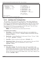
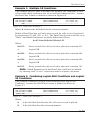
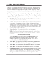
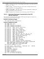
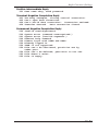
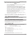
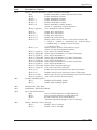
5.4.1. PBX Port A and PBX Port B
From the Port Selector Menu, type 1 (for PBX Port A) or 2 (for PBX
Port B) and then press [Enter]. Both configuration menus include the
following items:
Communication Settings:
1. Baud Rate: Selects the baud rate for this port. Any standard rate
from 1200 bps to 115.2K bps. (Default values are selected by SetUp Switches 4 and 5.)
2.
Bits/Parity: Selects Bits/Parity for this port; 8-None, 7-Even, 7-Odd,
or 7-None. (Default = 7-Even.)
3.
Stop Bits: Selects stop bits for this port. (Default = 1.)
4.
Handshake Mode: Selects flow control for this port; XON/XOFF,
RTS/CTS, both, or None. (Default = None.)
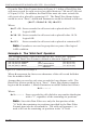
Input Parameters:
11. Time/Date Stamp: The date stamp can be inserted at the beginning of
each record received by this port. This prompt is used to disable the
function, or select the short format or long format. The short format
(PollCat III Compatible) lists Month, Date, Hour and Minute; the long
format lists Month, Date, Year, Hour, Minute, and Second.
(Default = Off.)
12. Serial Number Stamp: Inserts a six digit number at the beginning of
records received by this port. (Default = Off).
5-6
Configuration
PBX PORT A:
COMMUNICATION SETTINGS
1. Baud Rate:
9600
2. Bits/Parity:
7-Even
3. Stop Bits:
1
4. Handshake Mode: None
INPUT PARAMETERS
11. Time/Date Stmp:
12. Serial No Stmp:
13. Strip Non-Prnt:
14. End Character:
15. Alarm Filter:
16. Store Alm Data:
17. Data Filter:
18. PBX Inact Alm:
Off
Off
On
^J
Off
Alarm
Off
Off
FIELD SUPPESSION
31. Lucent Switch
Enter selection,
Press <ESC> to return to previous menu ...
Figure 5.4: PBX Port Configuration Menu (Port A Shown)
13. Strip Non-Printables: Conserves memory by excluding characters
such as Nuls and Dels. (Default = On.)
14. End Character: Defines the End-of-Record (EOR) character that
the VIP expects to see at the end of each record received at this port.
(Default = ^J (Line Feed).)
15. Alarm Filter: Enables/disables the Alarm Filter and selects the Alarm
Filter Format for this port. The Alarm Filter monitors data, and
notifies the user when specific types of data are detected. For more
information, please refer to Section 9. (Default = Off.)
16. Store Alarm Data: Determines where the VIP will store alarm data
received via this port. Alarm Records can be stored in the Alarm File,
the Standard (non-alarm) File, or both files. For more information,
please refer to Section 16.1.1. (Default = Alarm.)
17. Data Filter: Enables/disables the Data Filter and selects the Data
Filter Format used by this port. The Data Filter conserves memory and
cuts polling time by excluding records not needed for your application.
For more information, please refer to Section 8. (Default = Off.)
18. PBX Inactivity Alarm: Enables/disables the PBX Inactivity Alarm
and selects the format for this port. The inactivity alarm monitors the
flow of data from the PBX and notifies the user if the flow stops. For
further instructions, please refer to Section 10. (Default = Off.)
Field Suppression:
31. Lucent Switch: This Item can be used to suppress the phone number
field in certain data records, as described in Section 5.4.1.1. This
feature is useful in countries that prohibit the transfer of phone number
records via network.
5-7
PollCat NetLink-VIP & PollCat NLJ-VIP - User’s Guide
LUCENT SWITCH:
GENERAL PARAMETERS
1. Supp Number:
2. Supp Trunk:
3. Call Direction:
4. Num Chars Supp:
Off
Off
Outgoing
4
FIELD LOCATION
11. Dest Num Loc:
12. Src Num Loc:
13. In Trunk Loc:
14. Out Trunk Loc:
16
34
46
50
FIELD LENGTH
21. Dest Num Len:
22. Src Num Len:
23. In Trunk Len:
24. Out Trunk Len:
18
12
4
4
Enter selection,
Press <ESC> to return to previous menu ...
Figure 5.5: Field Suppression: The Lucent Switch Option
5.4.1.1. Field Suppression; The Lucent Switch Feature
This feature is used to suppress portions of the data record that may
contain phone numbers and trunk numbers, allowing HIPPA compliant data
transmission. This feature is useful in situations where either local laws
or regulating agencies prohibit the transmission of phone numbers. The
Lucent Switch configuration menu offers the following options:
General Parameters:
1. Suppress Number: When enabled, all or part of each phone number
will be suppressed and not included in transmitted call records. This
item can be used to select destination numbers, source numbers, both
types of numbers or neither (Off.) (Default = Off.)
2.
Suppress Trunk: When enabled, all or part of trunk numbers will be
suppressed and not included in transmitted call records. This item can
be used to select the inbound trunk, outgoing trunk, both or neither
(Off.) (Default = Off.)
3.
Call Direction: This item is used to determine if the VIP will
suppress incoming phone numbers, outgoing phone numbers or both
types of numbers. (Default = Outgoing.)
4.
Number of Characters Suppressed: The number of characters
(starting from the right hand edge of the field) that will be suppressed.
This value will be applied to both incoming calls and outgoing calls (if
selected via Item 3.) (1 to 32 Characters; Default = 4.)
5-8
Configuration
Field Location:
11. Destination Number Location: This item is used to define the
beginning of the field that is normally used to store the destination
phone number. (1 to 216 Characters; Default = 16.)
12. Source Number Location: Defines the beginning of the field
that is normally used to store the source phone number. (1 to 216
Characters; Default = 34.)
13. Inbound Trunk Location: Defines the beginning of the field that
is normally used to store the inbound trunk number. (1 to 216
Characters; Default = 46)
14. Outbound Trunk Location: Defines the beginning of the field that
is normally used to store the outbound trunk location. (1 to 216
Characters; Default = 50.)
Field Length:
21. Destination Number Length: This item is used to define the length
of the field that is normally used to store the destination phone number.
(1 to 32 Characters; Default = 18.)
22. Source Number Length: Defines the length of the field that is
normally used to store the source phone number. (1 to 32 Characters;
Default = 12.)
23. Inbound Trunk Length: Defines the length of the field that
is normally used to store the inbound trunk number. (1 to 32
Characters; Default = 4.)
24. Outbound Trunk Length: Defines the length of the field that
is normally used to store the outbound trunk number. (1 to 32
Characters; Default = 4.)
5-9
PollCat NetLink-VIP & PollCat NLJ-VIP - User’s Guide
AUXILIARY PORT:
COMMUNICATION SETTINGS
1. Baud Rate:
9600
2. Bits/Parity:
7-Even
3. Stop Bits:
1
4. Handshake Mode: None
INPUT PARAMETERS
11. Time/Date Stmp:
12. Serial No Stmp:
13. Strip Non-Prnt:
14. End Character:
15. Alarm Filter:
16. Store Alm Data:
17. Data Filter:
18. PBX Inact Alm:
19. Port Mode:
Off
Off
On
^J
Off
Alarm
Off
Off
Store Data
FIELD SUPPESSION
31. Lucent Switch
Enter selection,
Press <ESC> to return to previous menu ...
Figure 5.6: Auxiliary Port Configuration Menu
5.4.2. Auxiliary Port Configuration
The Auxiliary (AUX) Port can be connected to a third PBX SMDR port,
or used to pass commands to a connected device. To configure the AUX
Port, first go to the Port Selector Menu (Main Menu, item 22). Type 3 and
press [Enter]; the AUX Port Configuration menu will appear (Figure 5.6).
Note that the AUX Port is not present on NLJ-VIP units. The AUX Port
Configuration menu includes the following:
Note: NLJ-VIP units do not include an AUX Port.
Communication Settings:
1. Baud Rate: Selects the baud rate for this port; any standard rate
from 1200 bps to 115.2K bps. (Default value is selected by Set-Up
Switches 4 and 5.)
2.
Bits/Parity: Selects Bits/Parity for this port; 8-None, 7-Even, 7-Odd,
or 7-None. (Default = 7-Even.)
3.
Stop Bits: Selects stop bits for this port. (Default = 1.)
4.
Handshake Mode: Selects the flow control mode for this port; XON/
XOFF (Software), RTS/CTS (Hardware), both, or None.
(Default = None.)
Input Parameters:
11. Time/Date Stamp: The time/date stamp can be appended to the
beginning of each record received at this port. This prompt allows the
user to disable the function, or select short format or long format. The
short format (PollCat III Compatible) lists the Month, Date, Hour and
Minute; the long format lists the Month, Date, Year, Hour, Minute, and
Second. (Default = Off.)
5-10
Configuration
12. Serial Number Stamp: Inserts a six digit serial number at the
beginning of each record received by this port. (Default = Off.)
13. Strip Non-Printables: Conserves memory and cuts polling time
by excluding non-printable characters (such as Nuls and Dels) from
records received at this port. (Default = On.)
14. End Character: Defines the End-of-Record (EOR) character that
the VIP expects to see at the end of each record received at this port.
(Default = ^J (Line Feed).)
15. Alarm Filter: Enables/disables the Alarm Filter and selects the Alarm
Filter used by the AUX port. The Alarm Filter can notify the user
when specific types of data are detected. For more information, please
refer to Section 9. (Default = Off.)
16. Store Alarm Data: Determines where the VIP will store alarm data
received via this port. Alarm Records can be stored in the Alarm File,
the Standard (non-alarm) File, or both files. For more information,
please refer to Section 16.1.1. (Default = Alarm.)
17. Data Filter: Enables/disables the Data Filter and selects the Data
Filter used by this port. For more information on the Data Filter,
please refer to Section 8. (Default = Off.)
18. PBX Inactivity Alarm: Enables/disables the PBX Inactivity Alarm
for this port. The PBX Inactivity Alarm monitors the flow of data
from the PBX Ports and notifies the user if the flow stops. For more
information, please refer to Section 10. (Default = Off.)
19. Port Mode: Selects the operating mode for the AUX Port. If the
AUX Port will be connected to a PBX, the Port Mode should be set
to Store Data. If the AUX Port will be used to pass commands to a
connected device, the Port Mode should probably be set to Discard
Data. (Default = Store Data.)
Field Suppression:
31. Lucent Switch: This Item can be used to suppress the phone number
field in certain data records, as described in Section 5.4.1.1. This
feature is useful in countries that prohibit the transfer of phone number
records via network.
5-11
PollCat NetLink-VIP & PollCat NLJ-VIP - User’s Guide
CONSOLE PORT:
COMMUNICATION SETTINGS
1. Baud Rate:
9600
2. Bits/Parity:
8-None
3. Stop Bits:
1
4. Handshake Mode: RTS/CTS
GENERAL PARAMETERS
11. Command Echo:
12. Response Type:
13. “Sure” Prompt:
14. CMD Timeout:
15. Audit Trail:
OUTPUT PARAMETERS
21. Output Mode:
22. Data on ^B01:
23. Hold End Data:
24. Line # Tag:
25. Send Compress:
26. Auto Delete:
ASCII Record
On
On
Off
Off
Off
OUTPUT PARAMETERS (BINARY BLOCK)
27. Transmit Att:
3
28. Transmit Delay: 5 Secs
29. DLE Stuffing:
Off
On
Inhibit Menu
On
15 Mins
Off
ACTION PARAMETERS
16. Action Delay:
10 Secs
Enter selection, Press <ESC> to return to previous menu ...
Figure 5.7: Console Port Configuration
5.4.3. Console Port Configuration
The Console Port is used for connection to a local control device, such as a
PC or terminal. To configure the Console Port, first go to the Port Selector
Menu (Main Menu, item 22). Type 4 and press [Enter]. The Console Port
Configuration Menu (Figure 5.7) will be displayed. The following options
are available:
Communication Settings:
1. Baud Rate: Selects the baud rate for this port; any standard rate
from 1200 bps to 115.2K bps. (Default value is selected by Set-Up
Switches 1, 2, and 3.)
2.
Bits/Parity: Selects Bits/Parity for this port; 8-None, 7-Even, 7-Odd,
or 7-None. (Default = 8-None.)
3.
Stop Bits: Selects stop bits for this port. (Default = 1.)
4.
Handshake Mode: Selects the flow control mode for this port; XON/
XOFF (Software), RTS/CTS (Hardware), both, or None.
(Default = RTS/CTS.)
General Parameters:
11. Command Echo: Enables / Disables the command echo for this port.
During set-up, it may be helpful to enable the command echo. This
allows keystrokes sent to the VIP unit to be displayed on your monitor.
(Default = On.)
5-12
Configuration
12. Response Type: Determines how the port will react when command
mode is activated. If "Display Menu" is selected, the VIP will
immediately display the Main Menu when command mode is
activated. If "Inhibit Menu" is selected, the VIP will not display the
Main Menu until [Enter] is pressed. (Default = Inhibit Menu.)
13. "Sure" Prompt: When irreversible commands (such as "Erase Data")
are invoked at this port, the VIP can display the "Sure" prompt to
allow one last chance to verify that the command should be executed.
(Default = On.)
14. Command Timeout: Sets the Timeout value for this port. When the
VIP detects no command activity at this port for the specified timeout
period, the port will exit command mode and disconnect.
(Default =15 minutes.)
15. Audit Trail: Enables or Disables the Audit Trail function. When
enabled, the VIP will log command activity at this port. To review the
command activity log, please refer to Section 17.1.7. (Default = Off.)
Action Parameters:
16. Action Delay: When multiple alarm actions are directed to this
port, the action delay determines how much time will elapse between
actions. The Action Delay makes it easier to connect to the port, by
providing a window when the port is not busy sending out actions.
(Zero to 9999 Seconds; Default = 10 Seconds.)
Output Parameters:
21. Output Mode: Selects the data output format for this port; ASCII
Record, Binary Block, Xmodem, or ZModem.
(Default = ASCII Record.)
Note: When using ZModem Output Mode, please refer to the
cautions listed in Section 16.7.
22. Data on ^B01: If enabled, the VIP will immediately begin sending
data when the data release command is invoked (Menu or ^B01). If
disabled, the VIP will send the "READY" message, then wait for
Command ^B02 before releasing data. (Default = On.)
23. Hold End Data: At the end of each data release session, the VIP will
send the "End Data" message before returning to command mode.
When this option is enabled, this port will wait for Command ^B02
before sending the End Data message. (Default = On.)
5-13
PollCat NetLink-VIP & PollCat NLJ-VIP - User’s Guide
24. Line Number Tag: Inserts a Line Number at the beginning of each
record or block released by this port. These Line Numbers are not
stored in internal memory, but are added when data is released.
(Default = Off.)
25. Send Compressed: When this feature is enabled, data will be released
from this port in space compressed format. (Default = Off.)
26. Auto Delete: When enabled, data will be automatically deleted from
the VIP's memory at the end of each successful read. If the read
operation is interrupted, data will not be deleted. (Default = Off.)
Note: Before enabling the Auto Delete function, please refer to the
cautions listed in Section 16.6.
Output Parameters (Binary Block Mode Only):
27. Transmit Attempts: (Binary Mode Only) Determines how many
times this port will resend a block when there is a transmission
problem, or the connection is lost. (Zero to 99 attempts; Default = 3.)
28. Transmit Delay: (Binary Mode Only) Determines how long this port
will wait between transmit attempts. If this value is set to Zero, binary
data will be sent in a continuous block, without acknowledgment.
(Zero to 99 seconds; Default = 5 seconds.)
29. DLE Stuffing: (Binary Mode Only) Allows literal characters to be
inserted into binary data released by this port. (Default = Off.)
5-14
Configuration
MODEM PORT:
Modem Installed
COMMUNICATION SETTINGS
1. Baud Rate:
57600
2. Bits/Parity:
8-None
3. Stop Bits:
1
4. Handshake Mode: RTS/CTS
5. Reset string:
ATZ
6. Init String:
ATE0M0Q1&C1&D2S0
(Cont.):
=1
7. Hang-up String: (undefined)
(Cont.):
8. Reset Modem
GENERAL PARAMETERS
11. Command Echo:
12. Response Type:
13. “Sure” Prompt:
14. CMD Timeout:
15. Audit Trail:
On
Inhibit Menu
On
15 Mins
Off
ACTION PARAMETERS
16. Action Delay:
300 Secs
OUTPUT PARAMETERS
21. Output Mode:
22. Data on ^B01:
23. Hold End Data:
24. Line # Tag:
25. Send Compress:
26. Auto Delete:
ASCII Record
On
On
Off
Off
Off
OUTPUT PARAMETERS (BINARY BLOCK)
27. Transmit Att:
3
28. Transmit Delay: 5 Secs
29. DLE Stuffing:
Off
CALLOUT PARAMETERS
31. Dial Attempts:
32. Sequence Att:
33. Sequence Delay:
34. Imm Callout:
35. Imm Phone #:
(Cont.):
36. Dialback Scrty:
3
3
10 Mins
Off
(undefined)
On
Enter selection, Press <ESC> to return to previous menu ...
Figure 5.8: Modem Port Configuration Menu
5.4.4. Modem Port Configuration
To configure the Modem Port, go to the Port Selector Menu (Main Menu,
item 22), and select item 5. The Modem Port Configuration Menu will
appear as shown in Figure 5.8. The following options are available:
Communication Settings:
1. Baud Rate: Selects the baud rate for this port; any standard rate from
1200 to 115.2K bps. (Default = 57600.)
2.
Bits/Parity: Selects Bits/Parity for this port; 8-None, 7-Even, 7-Odd,
or 7-None. (Default = 8-None.)
3.
Stop Bits: Selects stop bits for this port. (Default = 1.)
4.
Handshake Mode: Selects the flow control mode for this port; XON/
XOFF (Software), RTS/CTS (Hardware), both, or None.
(Default = RTS/CTS.)
5.
Reset String: Defines the modem reset message. (Up to 16
characters; Default = ATZ.)
6.
Initialize String: Defines the modem initialization string. (Up to 32
characters; Default = ATE0M0Q1&C1&D2S0=1.)
7.
Hang-Up String: Defines the modem hang-up string. (Up to 32
characters; Default = undefined.)
8.
Reset Modem: Resets the internal modem.
5-15
PollCat NetLink-VIP & PollCat NLJ-VIP - User’s Guide
General Parameters:
11. Command Echo: Enables / disables command echo for this port.
During set-up, it may be helpful to enable Command Echo. This
allows keystrokes sent to the VIP to be displayed. (Default = On.)
12. Response Type: Determines how this port will react when command
mode is activated. If "Display Menu" is selected, the VIP will
immediately display the Main Menu when command mode is
activated. If "Inhibit Menu" is selected, the VIP will not display the
Main Menu until [Enter] is pressed. (Default = Inhibit Menu.)
13. "Sure" Prompt: When irreversible commands (such as "Erase Data")
are invoked at this port, the VIP can display the "Sure" prompt to
allow one last chance to verify that the command should be executed.
(Default = On.)
14. Command Timeout: Sets the Timeout value. When no additional
command activity is detected at this port during the specified timeout
period, the port will exit command mode and disconnect.
(Default =15 minutes.)
15. Audit Trail: Enables or Disables the Audit Trail function. When
enabled, the VIP will log command activity at this port. To review the
command activity log, please refer to Section 17.1.7. (Default = Off.)
Action Parameters:
16. Action Delay: When multiple alarm actions are directed to this
port, the action delay determines how much time will elapse between
actions. This makes it easier to connect, by providing a window when
the port is not busy sending out actions. (Zero to 9999 Seconds;
Default = 300 Seconds.)
Output Parameters:
21. Output Mode: Selects the data output format for this port; ASCII
Record, Binary Block, Xmodem or Zmodem.
(Default = ASCII Record.)
Note: When using Zmodem Output Mode, please refer to the
cautions listed in Section 16.7.
22. Data on ^B01: When enabled, the VIP will immediately begin
sending data when the data release command is invoked (Menu or
^B01). When disabled, the VIP will send the "READY" message, then
wait for Command ^B02 before releasing data. (Default = On.)
5-16
Configuration
23. Hold End Data: At the end of each data release session, the VIP will
send the "End Data" message before returning to command mode.
When this option is enabled, this port will wait for Command ^B02
before sending the End Data message. (Default = On.)
24. Line Number Tag: Inserts a Line Number at the beginning of each
record or block released by this port. These Line Numbers are not
stored in internal memory, but are added when data is released.
(Default = Off.)
25. Send Compressed: When this feature is enabled, data will be released
from this port in space compressed format. (Default = Off.)
26. Auto Delete: When enabled, data will be automatically deleted from
the VIP's memory at the end of each successful read. If the read is
interrupted, data will not be deleted. (Default = Off.)
Note: Before enabling the Auto Delete function, please refer to the
cautions listed in Section 16.6.
Output Parameters (Binary Block Mode Only):
27. Transmit Attempts: (Binary Mode Only) Determines how many
times this port will attempt to resend a block when there is a
transmission problem, or the connection is lost. (Zero to 99 attempts;
Default = 3.)
28. Transmit Delay: (Binary Mode Only) Determines how long this
port will wait between transmit attempts. Note that if this value is
set to Zero, binary data will be sent in a continuous block, without
acknowledgment. (Zero to 99 seconds; Default = 5 Seconds.)
29. DLE Stuffing: (Binary Mode Only) Allows literal characters to be
inserted into binary data released by this port. (Default = Off.)
Callout Parameters:
31. Dial Attempts: The number of times the modem will redial the
Callout Number when there is no answer, or the carrier is not received.
(Zero to 99 attempts; Default = 3.)
32. Sequence Attempts: The number of times the modem will restart the
callout routine if the defined number of dial attempts is performed and
there is no answer, or the carrier is not received. (Zero to 99 attempts;
Default = 3.)
33. Sequence Delay: The amount of time between sequence attempts.
(Zero to 999 minutes; Default = 10 Minutes.)
5-17
PollCat NetLink-VIP & PollCat NLJ-VIP - User’s Guide
34. Immediate Callout: Activates the Immediate Callout feature. When
enabled, the VIP will dial the Immediate Phone Number after the user
disconnects. Note that this feature must be enabled prior to each use,
and the Immediate Phone Number must be defined in order for this
feature to function. (Default = Off.)
35. Immediate Phone Number: Defines the number that is dialed when
an Immediate Callout is performed. (Up to 32 characters;
Default = undefined.)
36. Dialback Security: Defines and enables dialback security parameters.
For more information, please refer to Section 5.4.4.1. (Default = Off.)
5-18
Configuration
DIALBACK SECURITY:
1.
2.
3.
4.
Dialback Security:
On
Supervisor Dialback Phone #: (undefined)
User Dialback Phone #1:
(undefined)
User Dialback Phone #2:
(undefined)
Enter selection,
Press <ESC> to return to previous menu ...
Figure 5.9: Dialback Security Configuration Screen
5.4.4.1. Dialback Security
This feature provides an extra measure of security for modem access to
command mode. When this option is configured and enabled, the VIP will
dial a user-defined number before allowing access to command mode.
If Dialback Security is active, the VIP will display the Password prompt
when a user contacts the unit via modem. If the caller enters a valid
password, the VIP will then disconnect and call the user-defined number for
that password. After successfully contacting the dialback number, the VIP
will again display the password prompt. If a valid password is entered by
the answering party, the VIP will then allow access to command mode.
The Dialback Security feature will recognize up to three passwords; one
Supervisor Password and two User Passwords. The Supervisor password
allows access to all configuration menus. The User passwords will not
allow access to configuration menus.
To access the Dialback Security menu from the Modem Port Configuration
menu, type 36 and press [Enter]. The Dialback Security menu (Figure 5.8)
offers the following options:
1.
Dialback Security: Enables/disables the Dialback Security feature.
(Default = Off.)
2.
Supervisor Dialback Phone Number: The dialback number that will
be used when a caller enters the valid Supervisor Password. (Up to 32
characters; Default = undefined.)
3.
User Dialback Phone Number 1: The dialback number that will be
used when a caller enters the User 1 Password. (Up to 32 characters;
Default = undefined.)
4.
User Dialback Phone Number 2: The dialback number that will be
used when a caller enters the User 2 Password. (Up to 32 characters;
Default = undefined.)
5-19
PollCat NetLink-VIP & PollCat NLJ-VIP - User’s Guide
NETWORK PORT:
NIC Installed
COMMUNICATION SETTINGS
1. IP Address:
65.106.93.105
2. Subnet Mask:
255.255.255.0
3. Gateway Addr:
65.106.93.97
4. SNMP Manager 1: (undefined)
5. SNMP Manager 2: (undefined)
6. SNMP Community: public
7. Reset Network
8. Send MSS:
1460
9. Send Email
10. Ping
GENERAL PARAMETERS
11. Command Echo:
12. Response Type:
13. “Sure” Prompt:
14. CMD Timeout:
15. Audit Trail:
OUTPUT PARAMETERS
21. Output Mode:
22. Data on ^B01:
23. Hold End Data:
24. Line # Tag:
25. Send Compress:
26. Auto Delete:
ASCII Record
On
On
Off
Off
On
OUTPUT PARAMETERS (BINARY BLOCK)
27. Transmit Att:
3
28. Transmit Delay: 5 Secs
29. DLE Stuffing:
Off
On
Inhibit Menu
On
15 Mins
Off
ACTION PARAMETERS
16. Action Delay:
10 Secs
Enter selection, Press <ESC> to return to previous menu ...
Figure 5.10: Network Configuration Menu
5.4.5. Network Port Configuration
Settings for network parameters, such as the IP Address and Subnet Mask,
will be determined by your individual network configuration. Please
contact your network administrator for appropriate settings, then assign
parameters as described in this section.
To configure the Network Port, go to the Port Selector Menu (Main Menu,
item 22), and select item 6. The Network Port Configuration Menu
(Figure 5.10) offers the following options:
Communication Settings:
1. IP Address: The VIP's IP Address (Default = undefined.)
2.
Subnet Mask: Defines the VIP's subnet mask.
(Default = 255.255.255.0.)
3.
Gateway Address: Defines the VIP's Gateway Address.
(Default = undefined.)
4.
SNMP Manager 1: Defines the IP Address for the first SNMP
Manager. The VIP allows definition of two SNMP Managers.
(Default = undefined.)
5.
SNMP Manager 2: Defines the IP Address for the second SNMP
Manager. (Default = undefined.)
6.
SNMP Community: Defines the SNMP Community.
(Default = public.)
7.
Reset Network: Reinitializes the network port.
5-20
Configuration
8.
Send MSS: Sets the Maximum Segment Size for TCP/IP packets sent
by the VIP. (Default = 1460.)
9.
Send Email: This item is used to define parameters that are employed
when the VIP automatically generates an email or text message in
order to notify the operator that an alarm has been detected. Note that
these same parameters are also used when the "Scheduled Actions"
feature is configured to send email or text messages. Email parameters
are described further in Section 5.4.5.1.
10. Ping: This feature can be used to determine if a given piece of remote
network hardware is online and is able to communicate with the VIP
unit. For more information, please refer to Section 5.4.5.2
General Parameters:
11. Command Echo: Enables / Disables the command echo for this
port. During set-up, it may be helpful to enable Command Echo. This
allows keystrokes sent to the VIP to be displayed on your monitor.
(Default = On.)
12. Response Type: Determines how this port will react when command
mode is activated. If "Display Menu" is selected, the VIP will
immediately display the Main Menu when command mode is
activated. If "Inhibit Menu" is selected, the VIP will not display the
Main Menu until [Enter] is pressed. (Default = Inhibit Menu.)
13. "Sure" Prompt: When irreversible commands (such as "Erase Data")
are invoked, this port can display the "Sure" prompt to allow one last
chance to verify that the command should be executed.
(Default = On.)
14. Command Timeout: Sets the Timeout value. If no additional
command activity is detected at this port during the defined timeout
period, this port will exit command mode and disconnect.
(Default =15 minutes.)
15. Audit Trail: Enables or Disables the Audit Trail function. When
enabled, the VIP will log command activity at this port. To review the
command activity log, please refer to Section 17.1.7. (Default = Off.)
Action Parameters:
16. Action Delay: When multiple alarm actions are directed to this
port, the action delay determines how much time will elapse between
actions. This makes it easier to connect to the port, by providing a
window when the port is not busy sending out actions. (Zero to 9999
Seconds; Default = 10 Seconds.)
5-21
PollCat NetLink-VIP & PollCat NLJ-VIP - User’s Guide
Output Parameters:
21. Output Mode: Selects the data output format for this port; ASCII
Record, Binary Block, Xmodem or Zmodem.
(Default = ASCII Record.)
Note: When using Zmodem Output Mode, please refer to the
cautions listed in Section 16.7.
22. Data on ^B01: When enabled, the VIP will immediately begin
sending data when the data release command is invoked (Menu or
^B01). When disabled, the VIP will send the "READY" message, then
wait for Command ^B02 before releasing data. (Default = On.)
23. Hold End Data: At the end of each data release session, the VIP will
send the "End Data" message before returning to command mode.
When "Hold End Data" is enabled, this port will wait for Command
^B02 before sending the End Data message. (Default = On.)
24. Line Number Tag: Inserts a Line Number at the beginning of each
record or block released by this port. These Line Numbers are not
stored in the VIP's internal memory, but are added when data is
released. (Default = Off.)
25. Send Compressed: When this feature is enabled, data will be released
from this port in space compressed format. (Default = Off.)
26. Auto Delete: When enabled, data will be automatically deleted from
the VIP's memory at the end of each successful read. If the read is
interrupted, data will not be deleted. (Default = Off.)
Note: Before enabling the Auto Delete function, please refer to the
cautions listed in Section 16.6.
Output Parameters (Binary Block Mode Only):
27. Transmit Attempts: (Binary Mode Only) Determines how many
times this port will resend a block after a transmission interruption, or
lost connection. (Zero to 99 attempts; Default = 3.)
28. Transmit Delay: (Binary Mode Only) Determines how long this port
will wait between transmit attempts. If this value is set to Zero, binary
data will be sent in a continuous block, without acknowledgment.
(Zero to 99 seconds; Default = 5 seconds.)
29. DLE Stuffing: (Binary Mode Only) Allows literal characters to be
inserted into binary data released by this port. (Default = Off.)
5-22
Configuration
SEND EMAIL:
SMTP SERVER PARAMETERS
1. IP Address:
(undefined)
2. Port Number:
25
3. User Name:
(undefined)
(Cont.):
(Cont.):
4. Password:
(undefined)
5. Auth Type:
LOGIN
MISCELLANEOUS
11. Send Test Email
12. Stop Email Sess
13. Last Email Stat
EMAIL PARAMETERS
21. From Name:
22. From Address:
(Cont.):
(Cont.):
23. To Name #1:
24. To Address #1:
(Cont.):
(Cont.):
25. To Name #2:
26. To Address #2:
(Cont.):
(Cont.):
27. Priority:
28. Subject:
(Cont.):
(Cont.):
(undefined)
(undefined)
(undefined)
(undefined)
(undefined)
(undefined)
Normal
(undefined)
Enter selection,
Press <ESC> to return to previous menu ...
Figure 5.11: The Send Email Configuration Menu
5.4.5.1. The Email & Text Messaging Parameters Menu
When an alarm or scheduled event occurs, the VIP can notify you via pager,
callout, SNMP Trap, Console Port Action, Email or Text Message.
Configuring the Email option consists of two steps: Selecting Email
Parameters (communication parameters and email addresses) and then
enabling the Email option for the desired alarm filters and scheduled events.
The procedure for defining email and text message parameters is discussed
below, and the procedure for enabling email and text messaging for specific
alarms and scheduled events is discussed in Sections 13 and 14.
To access the email configuration menu from the Network Port Parameters
menu, type 9 and press [Enter]. The "Send Email" parameters menu
(Figure 5.11) can be used to define the following parameters.
SMTP Server Parameters
1. IP Address: The IP Address for your SMTP Email Server.
(Default = undefined.)
2.
Port Number: The TCP Port number that is used when sending email
or text messages. The port number can be any valid port, from 1 to
65535, but cannot be a Telnet port, FTP port, HTTP port, or the PBXIP Port. (Default = 25.)
3.
User Name: The username that is normally entered when logging on
to your SMTP Server. (Default = undefined.)
4.
Password: The password that is normally entered when logging on to
your SMTP Server. (Default = undefined.)
5-23
PollCat NetLink-VIP & PollCat NLJ-VIP - User’s Guide
5.
Auth Type: The type of authentication that is used when logging onto
your SMTP Server. (Default = Login.)
Miscellaneous:
11. Send Test Email: Sends a test email or text message, based on the
currently defined email parameters.
12. Stop Email Session: Cancels any email action currently in progress.
13. Last Email Stat: Lists the current status of the last email sent.
Email Parameters:
21. From Name: When an email or text message is sent, this name will
appear in the "From" field. (Default = undefined.)
22. From Address: When an email or text message is sent, this address
will appear in the "From Address" field. (Default = undefined.)
23. To Name #1: Defines the name for the first optional email or text
message recipient. When email parameters are properly defined, the
"Email To" option in the Alarm Configuration Menus and Scheduled
Action Menus can be used to select Name Number One to receive an
email or text message when an alarm action or scheduled action is
generated. (Default = undefined.)
24. To Address #1: Defines the email address for Name Number One.
When email parameters are properly defined, the "Email To" option in
the Alarm Configuration Menus and Scheduled Action Menus can be
used to select Name Number One to receive an email or text message
when an Alarm Action or Scheduled Action is generated.
(Default = undefined.)
25. To Name #2: Defines the name for the second optional email or text
message recipient. (Default = undefined.)
26. To Address #2: Defines the email address for Name Number Two.
(Default = undefined.)
27. Priority: Defines the priority assigned to email generated when the
"Email To" option is selected as an Alarm Action or Scheduled Action.
(Default = Normal.)
28. Subject: Defines the subject line for email or text messages generated
when the "Email To" option is selected as an Alarm Action or
Scheduled Action. (Default = undefined.)
5-24
Configuration
PING:
GENERAL PARAMETERS
1. IP Address:
2. Send Pkts:
3. Con. Lost Pkts:
4. Response Delay:
5. Pkt Delay:
6. Pkt Size:
(undefined)
4
4
1 Sec
1 Sec
32
MISCELLANEOUS
11. Start Ping
12. Stop Ping Sess
13. Last Ping Stat
Enter selection,
Press <ESC> to return to previous menu ...
Figure 5.12: The Ping Configuration Menu
5.4.5.2 The Ping Function
The VIP’s Network Port Configuration Menu includes a Ping function,
which can be used to determine if a given piece of remote network
hardware is online and able to communicate with the VIP.
The Ping Configuration Menu (Figure 5.12) offers the following options:
1.
IP Address: The IP Address for the device that you wish to ping.
(Default = undefined.)
2.
Send Pkts: The number of ping packets that will be sent.
(Default = 4.)
3.
Con. Lost Pkts: The number of consecutive lost packets.
(Default = 4.)
4.
Response Delay: (Default = 1 second.)
5.
Packet Delay: (Default = 1 second.)
6.
Packet Size: (Default = 32.)
Miscellaneous:
11. Start Ping: Starts the ping session based on the currently defined
parameters.
12. Stop Ping Session: Stops the current Ping Session.
13. Last Ping Stat: Displays the statistics/results for the most recent ping
session.
5-25
PollCat NetLink-VIP & PollCat NLJ-VIP - User’s Guide
PBX IP PORT:
COMMUNICATION SETTINGS
1. Service:
On
2. Port Number:
9000
3. Window Size:
6
4. Keep Alive Send: 60 Secs
5. Keep Alive Resp: 60 Secs
6. SDM Resp:
30 Secs
MISCELLANEOUS
21. Disconnect
22. Last Status
INPUT PARAMETERS
11. Time/Date Stmp:
12. Serial No Stmp:
13. Strip Non-Prnt:
14. End Character:
15. Alarm Filter:
16. Store Alm Data:
17. Data Filter:
18. PBX Inact Alm:
Off
Off
On
^J
Off
Alarm
Off
Off
FIELD SUPPESSION
31. Lucent Switch
Enter selection,
Press <ESC> to return to previous menu ...
Figure 5.13: The PBX IP Port Configuration Menu
5.4.6. PBX IP Port Configuration
The PBX IP Port allows the VIP to collect data via network connection,
from an RSP compatible PBX, such as an Avaya PBX Switch. To configure
the PBX IP Port, first go to the Port Configuration Menu (Main Menu, Item
22.) Type 7 and press [Enter]. The menu shown in Figure 5.13 will be
displayed. The following options are available:
Notes:
• In most cases, the only configuration required, is to enable the
PBX IP Service and select the Port Number. The default settings
for the other parameters in the PBX IP Port Configuration menu
will generally function in most network environments.
• The proper settings for the "Window Size," "Keep Alive Send,"
"Keep Alive Resp." and "SDM Resp" parameters are determined
by the nature of your network environment.
• If an asterisk (*) appears next to a menu item, this indicates that
the change cannot be implemented until later. For example, an
asterisk will appear next to the Port Number if that Port Number
is already in use.
Communication Settings:
1. Service: Enables/Disables the PBX IP Port. In order for the VIP to
receive PBX data via network, this item must be "On."
(Default = On.)
2.
Port Number: The RSP Port Number. Cannot be a Telnet Port, FTP
Port, SMTP Port or HTTP Port. (From 1 to 65535; Default = 9000.)
3.
Window Size: The RSP Window Size. (From 1 to 255; Default = 6.)
5-26
Configuration
4.
Keep Alive Send: The "keep alive send" timeout in seconds.
(From 1 to 3600; Default = 60 Seconds.)
5.
Keep Alive Response: The "keep alive response" timeout in seconds.
(From 1 to 3600; Default = 60 Seconds.)
6.
SDM Response: The session disconnect message response timeout in
seconds. (From 1 to 3600; Default = 30 Seconds.)
Input Parameters:
11. Time/Date Stamp: The date stamp can be inserted at the beginning of
each record received by this port. This prompt is used to disable the
function, or select the short format or long format. The short format
(PollCat III Compatible) lists Month, Date, Hour and Minute; the long
format lists Month, Date, Year, Hour, Minute, and Second.
(Default = Off.)
12. Serial Number Stamp: Inserts a six digit number at the beginning of
each record received by this port. (Default = Off.)
13. Strip Non-Printables: Conserves memory by excluding characters
such as Nuls and Dels. (Default = On.)
14. End Character: Defines the End-of-Record (EOR) character that the
VIP will expect to see at the end of each record received at this port.
(Default = ^J (Line Feed).)
15. Alarm Filter: Enables/disables the Alarm Filter and selects the Alarm
Filter Format that will be used by this port. The Alarm Filter monitors
data and provides notification when specific types of data are detected.
For more information, please refer to Section 9. (Default = Off.)
16. Store Alarm Data: Determines where the VIP will store alarm data
received via this port. Alarm Records can be stored in the Alarm File,
the Standard (non-alarm) File, or both files. For more information,
please refer to Section 16.1.1. (Default = Both.)
5-27
PollCat NetLink-VIP & PollCat NLJ-VIP - User’s Guide
17. Data Filter: Enables/disables the Data Filter, and selects the Data
Filter Format that will be used by this port. The Data Filter conserves
memory and cuts polling time by excluding records not needed for
your application. For more information, please refer to Section 8.
(Default = Off.)
18. PBX Inactivity Alarm: Enables/disables the PBX Inactivity Alarm
and selects the format for this port. The inactivity alarm monitors the
flow of data from the PBX and provides notification if the flow stops.
For further instructions, please refer to Section 10. (Default = Off.)
Miscellaneous:
21. Disconnect: Terminates the connection to the RSP server.
22. Last Status: Displays the current status of the RSP connection.
Field Suppression:
31. Lucent Switch: This Item can be used to suppress the phone number
field in certain data records, as described in Section 5.4.1.1. This
feature is useful in countries that prohibit the transfer of phone number
records via network.
5-28
6. Menu System Description
The VIP operating system features a series of menus, which are used to
select options, invoke commands, and review status. This section provides
an overview of the VIP operating system, in order to help you locate
specific items in the various submenus.
6.1. Firmware Tree
Command functions are accessed via the Main Menu, which is the first
screen displayed when command mode is activated. The Main Menu
branches off into a series of submenus. Each submenu is dedicated to
a specific task, such as port configuration, buffer management, etc. To
access a submenu, type the number for the desired item and press [Enter].
Main Menu Item
Submenu(s)/Function(s)
1.
Status Displays
Display Status Screens for user-defined parameters, memory
usage, and alarm conditions (See Section 7.)
2.
Buffer Functions
1.
2.
3.
4.
5.
6.
7.
8.
Set Read Session Parameters
Set Partition
Release Partition
Enter Read Session
Erase Partition Data
Erase All Data
Erase All Data & Clear Alarm Counters
Release Remote Partition
3.
System Functions
1.
2.
3.
4.
5.
6.
7.
8.
Security Level
PassThrough Mode
Monitor Mode
Clear Alarm Condition
Clear Alarm Clue Counters
Download Parameters
Audit Trail Functions
Upload Firmware
4.
System Diagnostics
1.
2.
3.
4.
Load & Test Memory
Send Test Message
Test Pager
Send Test SNMP Trap(s)
5.
^Bxx Command Help
Lists all ^Bxx format (manually entered) commands. (See
Section 19). "A" option allows access to menu with additional
command help.
6.
Recall Parameters
Restores previously saved parameters.
7.
Save Operating
Parameters
Writes user-defined parameters from temporary memory to flash
memory.
8.
Exit Command Mode
Exits from command mode, disconnects, and puts Console Port
to sleep.
9. - 20.
Reserved for Future Use.
6-1
PollCat NetLink-VIP & PollCat NLJ-VIP - User’s Guide
Main Menu Item
Submenu(s)/Function(s)
21. Default Parameters
Resets all parameters to default settings. Offers the option to
include or exclude network parameters and Alarm Filter and
Data Filter configurations.
22. Port Configuration
1.
PBX Port A
Communication Settings
1. Baud Rate
2. Bits/Parity
3. Stop Bits
4. Handshake Mode
Input Parameters
11. Time Date Stamp
12. Serial Number Stamp
13. Strip Non-Printable Characters
14. End Character
15. Alarm Filter
16. Store Alarm Data
17. Data Filter
18. PBX Inactivity Alarm
Field Suppression
31. Lucent Switch
2.
PBX Port B
(Note: Not
included on
NLJ-VIP units.)
Communication Settings
1. Baud Rate
2. Bits/Parity
3. Stop Bits
4. Handshake Mode
Input Parameters
11. Time Date Stamp
12. Serial Number Stamp
13. Strip Non-Printable Characters
14. End Character
15. Alarm Filter
16. Store Alarm Data
17. Data Filter
18. PBX Inactivity Alarm
Field Suppression
31. Lucent Switch
3.
Auxiliary Port
(Note: Not
included on
NLJ-VIP units.)
Communication Settings
1. Baud Rate
2. Bits/Parity
3. Stop Bits
4. Handshake Mode
Input Parameters
11. Time Date Stamp
12. Serial Number Stamp
13. Strip Non-Printable Characters
14. End Character
15. Alarm Filter
16. Store Alarm Data
17. Data Filter
18. PBX Inactivity Alarm
19. Port Mode
Field Suppression
31. Lucent Switch
6-2
Menu System Description
Main Menu Item
Submenu(s)/Function(s)
22. Port Configuration
(Continued)
4.
Console Port
Communication Settings
1. Baud Rate
2. Bits/Parity
3. Stop Bits
4. Handshake Mode
General Parameters
11. Command Echo
12. Response Type
13. "Sure" Prompt
14. Command Timeout
15. Audit Trail
Action Parameters
16. Action Delay
Output Parameters
21. Output Mode
22. Data on ^B01
23. Hold End Data
24. Line Number Tag
25. Send Compressed
26. Auto Delete
Output Params. (Binary Block)
27. Transmit Attempts
28. Transmit Delay
29. DLE Stuffing
5.
Modem Port
Communication Settings
1. Baud Rate
2. Bits/Parity
3. Stop Bits
4. Handshake Mode
5. Reset String
6. Initialize String
7. Hang-Up String
8. Reset Modem
General Parameters
11. Command Echo
12. Response Type
13. "Sure" Prompt
14. Command Timeout
15. Audit Trail
Action Parameters
16. Action Delay
Output Parameters
21. Output Mode
22. Data on ^B01
23. Hold End Data
24. Line Number Tag
25. Send Compressed
26. Auto Delete
Output Params. (Binary Block)
27. Transmit Attempts
28. Transmit Delay
29. DLE Stuffing
Callout Parameters
31. Dial Attempts
32. Sequence Attempts
33. Sequence Delay
34. Immediate Callout
35. Immediate Phone Number
36. Dialback Security
6-3
PollCat NetLink-VIP & PollCat NLJ-VIP - User’s Guide
Main Menu Item
Submenu(s)/Function(s)
22. Port Configuration
(Continued)
6.
Network Port
Communication Settings
1. IP Address
2. Subnet Mask
3. Gateway Address
4. SNMP Manager 1
5. SNMP Manager 2
6. SNMP Community
7. Reset Network Port
8. Send MSS
9. Send Email
10. Ping
General Parameters
11. Command Echo
12. Response Type
13. "Sure" Prompt
14. Command Timeout
15. Audit Trail
Action Parameters
16. Action Delay
Output Parameters
21. Output Mode
22. Data on ^B01
23. Hold End Data
24. Line Number Tag
25. Send Compressed
26. Auto Delete
Output Parameters (Binary Block)
27. Transmit Attempts
28. Transmit Delay
29. DLE Stuffing
7.
PBX IP Port
Communication Settings
1. Service
2. Port Number
3. Window Size
4. Keep Alive Send
5. Keep Alive Response
6. SDM Response
Input Parameters
11. Time/Date Stamp
12. Serial Number Stamp
13. Strip Non-Printables
14. End Character
15. Alarm Filter
16. Store Alarm Data
17. Data Filter
18. PBX Inactivity Alarm
Miscellaneous
21. Disconnect
22. Last Status
Field Suppression
31. Lucent Switch
6-4
Menu System Description
Main Menu Item
Submenu(s)/Function(s)
23. System Parameters
1.
2.
3.
4.
5.
6.
7.
Supervisor Password
User Password 1
User Password 2
Site ID Message
Wrap-Around
Real Time Clock
Alarm Data Wrap-Around
24. Scheduled Action
Parameters
1.
Scheduled
Action #1
Schedule
1. Schedule Action (On/Off)
2-8. Define Schedule
Exclusions (MM/DD)
9. Add Exclusion
10. Delete Exclusion
Action Parameters
11. Action
12. Phone Number
13. Pager ID 1
14. Pager ID 2
15. Pager ID 3
16. SNMP Management
17. Output Contacts
18. Message
19. Auto Execute
20. Execute Commands
21. Email To
2.
Scheduled
Action #2
Schedule
1. Schedule Action (On/Off)
2-8. Define Schedule
Exclusions (MM/DD)
9. Add Exclusion
10. Delete Exclusion
Action Parameters
11. Action
12. Phone Number
13. Pager ID 1
14. Pager ID 2
15. Pager ID 3
16. SNMP Management
17. Output Contacts
18. Message
19. Auto Execute
20. Execute Commands
21. Email To
1.
Alarm Filter 1
1.
2.
3.
4.
5.
6.
25. Alarm Configuration
Define Format
Display Clue Details
Define Clues
Edit Clues
Delete Clues
Alarm Counter Reset Time
6-5
PollCat NetLink-VIP & PollCat NLJ-VIP - User’s Guide
Main Menu Item
Submenu(s)/Function(s)
25. Alarm Configuration
(Continued)
2.
Alarm Filter 2
1.
2.
3.
4.
5.
6.
3.
PBX Inactivity
Alarm 1
Schedule
1.
Weekday Alarm (On/Off)
2-5. Weekday Schedules & Timers
6.
Weekend Alarm (On/Off)
7-10. Weekend Schedules & Timers
Exclusions (MM/DD)
11. Add Exclusion
12. Delete Exclusion
Alarm Action Parameters
13. Action
14. Phone Number
15. Pager ID 1
16. Pager ID 2
17. Pager ID 3
18. SNMP Management
19. Output Contacts
20. Message
21. Auto Execute
22. Execute Commands
23. Email To
4.
PBX Inactivity
Alarm 2
Schedule
1.
Weekday Alarm
2-5. Weekday Schedules & Timers
6.
Weekend Alarm
7-10. Weekend Schedules & Timers
Exclusions (MM/DD)
11. Add Exclusion
12. Delete Exclusion
Alarm Action Parameters
13. Action
14. Phone Number
15. Pager ID 1
16. Pager ID 2
17. Pager ID 3
18. SNMP Management
19. Output Contacts
20. Message
21. Auto Execute
22. Execute Commands
6-6
Define Format
Display Clue Details
Define Clues
Edit Clues
Delete Clues
Alarm Counter Reset Time
Menu System Description
Main Menu Item
Submenu(s)/Function(s)
25. Alarm Configuration
(Continued)
5.
80% Full Alarm
1.
2.
3.
4.
5.
6.
7.
8.
9.
10.
11.
12.
80% Full Alarm
Action
Phone Number
Pager ID 1
Pager ID 2
Pager ID 3
SNMP Management
Output Contacts
Message
Auto Execute
Execute Commands
Email To
6.
Input Contact
Alarm
(Optional: Not
available on
NLJ-VIP)
1.
2.
3.
4.
Input Contact 1 Alarm
Input Contact 2 Alarm
Input Contact 3 Alarm
Input Contact 4 Alarm
Output Contacts (Idle/No Alarm)
(Optional: Not Available on NLJ-VIP)
7. Contacts 1/2/3/4
Default Alarm Action Parameters
8. Action
9. Phone Number
10. Pager ID 1
11. Pager ID 2
12. Pager ID 3
13. SNMP Management
14. Output Contacts 1/2/3/4
15. Message
16. Auto Execute
17. Execute Commands
18. Send Alarm Records
19. Email To
26. Data Filter
Configuration
1.
Data Filter 1
1.
2.
3.
4.
5.
6.
Data Filter Action
Define Format
Display Clue Details
Define Clues
Edit Clues
Delete Clues
2.
Data Filter 2
1.
2.
3.
4.
5.
6.
Data Filter Action
Define Format
Display Clue Details
Define Clues
Edit Clues
Delete Clues
6-7
PollCat NetLink-VIP & PollCat NLJ-VIP - User’s Guide
Main Menu Item
Submenu(s)/Function(s)
27. FTP Push
Configuration
FTP Server Parameters
1. Server Address
2. User Name
3. Password
4. Account
5. Directory
6. File Name
7. File Mode
8. File Extension Incrementing
Action Parameters
11. Read Session
12. Push Action
13. Periodic Push
14. Transmit Attempts
15. Transmit Delay
16. Auto Delete
17. FTP Push Start Time
Miscellaneous
21. Force FTP Push
22. Test FTP Push
23. Stop FTP Push
28. FTP Server
Configuration
FTP Server Parameters
1. User Name
2. Password
3. Filename
4. Auto Delete
5. Audit Trail
Miscellaneous
11. Stop FTP Session
6-8
7. Status Screens
The VIP includes a series of Status Screens that list the current state of all
program features and options.
During normal operation, these screens are used to check memory
conditions, review alarm status, and display the standing of the VIP options
and parameters. The Status Screens are also helpful during Setup and
configuration; allowing the user to determine if parameters need to be
changed.
This section summarizes the VIP's various Status Screens, and explains
individual items in each screen. To access the Status Screens, go to the
Main Menu, type 1 and press [Enter]. The VIP will display the screen
shown in Figure 7.1 below.
STATUS DISPLAYS:
1.
2.
3.
4.
5.
6.
7.
8.
Buffer Status
File List
System Status
Scheduled Action 1
Scheduled Action 2
Dialback Security
Data Filters & Alarms
Alarm Condition
21.
22.
23.
24.
25.
26.
27.
28.
PBX Port A
PBX Port B
AUX Port
Console Port
Modem Port
Network Port
Network Status
PBX IP Port
11.
12.
13.
14.
15.
PBX Inactivity Alarm 1
PBX Inactivity Alarm 2
80% Full Alarm
Input Contact Alarm
Reason For Action
31.
32.
33.
34.
35.
36.
37.
38.
Alarm
Alarm
Alarm
Alarm
Alarm
Alarm
Alarm
Alarm
Filter
Filter
Filter
Filter
Filter
Filter
Filter
Filter
1
2
1
2
1
2
1
2
Clue
Clue
Clue
Clue
Clue
Clue
Clue
Clue
Status
Status
Status
Status
Status
Status
Status
Status
(PBX-A)
(PBX-A)
(PBX-B)
(PBX-B)
(AUX)
(AUX)
(PBX IP)
(PBX IP)
Enter selection,
Press <ESC> to return to previous menu ...
Figure 7.1: Status Display Menu
7-1
PollCat NetLink-VIP & PollCat NLJ-VIP - User’s Guide
PollCat NetLink-VIP
BUFFER STATUS:
Unit Capacity:
Space Used:
Space Remaining:
Percent Full:
Total Record Ct:
Version 1.06
11/08/2005 Tue 11:29
1% Full
16 MB
16 KB
15 MB
1%
44
PARTITION RECORD COUNT
Console Port:
None
Modem Port:
None
Telnet Port #1:
None
Telnet Port #2:
None
Telnet Port #3:
None
FTP Push:
None
FTP Server:
None
Press <Enter> to return to menu ...
Figure 7.2: Buffer Status Screen
7.1. Buffer Status Screen
As shown in Figure 7.2, the Buffer Status screen lists current memory
conditions, including the following items:
• Unit Capacity: The total amount of internal flash memory.
• Space Used: The approximate amount of memory currently in use.
• Space Remaining: The approximate amount of free memory.
• Percent Full: The approximate percentage of memory currently in
use.
• Total Record Count: The total number of records stored.
• Partition Record Count: The number of records in the partitions for
the Console Port, Modem Port, Telnet Ports, and the FTP functions.
When data is released, each command port or FTP function is
temporarily designated as "owner" of a specific type of record (see
Section 16). For example, the Console port may own all records
received via PBX Port A, or the Modem Port may own all records for
Alarm Filter 1.
Console Port: The number of records in the partition owned by the
Console Port.
Modem Port: The number of records in the partition owned by the
Modem Port.
Telnet Ports 1 to 3: The number of records in the partitions owned
by each Telnet port.
FTP Push and FTP Server: The number of records in the
partitions owned by each FTP function.
7-2
Status Screens
PollCat NetLink-VIP
FILE LIST:
Version 1.06
11/08/2005 Tue 11:31
1% Full
Port
Data Type
Total Record Ct
Partition Record Ct
Partition Owner
------------------------------------------------------------------------------PBX-A
Standard
44
0
None
Press <Enter> to return to menu ...
Figure 7.3: File List (Sample Values Shown)
7.2. File List Screen
As shown in Figure 7.3, this screen shows a breakdown of the types of
records stored in buffer memory. Records are listed according to Data Type
and Receiving Port. There are three Data Types; Standard (Non-Alarm),
Alarm Filter 1, and Alarm Filter 2. There are three Receiving Ports; PBX
Port A, PBX Port B, and the AUX Port. When Data Type and Receiving
Port are combined, this provides nine possible file types. For more
information, please refer to Section 16.1.1.
The File List includes the following information:
• Port: The Input Port (A, B, AUX) that received the records.
• Data Type: The type of record is listed as follows:
Standard: (Non-Alarm) Records that did not match an Alarm Clue.
Alarm Filter 1: Records that match any Clue from Alarm Filter 1.
Alarm Filter 2: Records that match any Clue from Alarm Filter 2.
• Total Record Count: The total number of records of this type,
including records that may have been stored outside of the current
partition after the partition was set.
• Partition Record Count: The number of records in this partition.
• Partition Owner: The name of the command port (Console Port,
Modem Port, or Net Port) or FTP Function that owns the partition for
this type of record. When data is released, each command port or FTP
Function is temporarily designated as "owner" of a specific type of
record. For example, the Console port may own all records received
via PBX Port A, or the Modem Port may own all records that match a
clue for Alarm Filter 1.
7-3
PollCat NetLink-VIP & PollCat NLJ-VIP - User’s Guide
PollCat NetLink-VIP
SYSTEM STATUS:
Version 1.06
MEMORY CONFIGURATION
Module #1:
16 MB
Module #2:
Not installed
Module #3:
Not installed
Module #4:
Not installed
Base Memory:
Not used
Unit Capacity:
16 MB
COMMUNICATION SETTINGS
PBX Port A:
9600,E,7,1,None
PBX Port B:
9600,E,7,1,None
Auxiliary Port:
9600,E,7,1,None
Console Port:
9600,N,8,1,RTS
Modem Port:
57600,N,8,1,RTS
COMMAND PORT STATUS:
Console Port:
Off Line
Modem Port:
Off Line
11/08/2005 Tue 11:33
SYSTEM PARAMETERS
Spvsr Password:
User Password 1:
User Password 2:
Site ID Msg:
(Cont.):
Wrap-Around:
Alm Data Wrap-Arnd:
1% Full
(...)
SMDR
(undefined)
(undefined)
Off
Off
DIP SWITCH SETTINGS
SW-1 SW-2 SW-3 SW-4 SW-5 SW-6 SW-7 SW-8
Down Down Down Down Down Down Up
Down
NETWORK PORT STATUS:
Telnet Port #1:
On Line
Telnet Port #2:
Off Line
Telnet Port #3:
Off Line
FTP Push:
Off Line
FTP Server:
Off Line
Press <Enter> to return to menu ...
Figure 7.4: System Status Screen
7.3. System Status Screen
As shown in Figure 7.4, this screen summarizes communication parameters
and general system parameters. The System Status Screen also lists
installed memory modules, command port connection status, and Set-Up
Switch Status. The System Status Screen lists the following:
• Memory Configuration: Installed memory modules, the amount of
base memory, and the total memory capacity.
• Communication Settings: Communication settings for PBX Ports
A and B, the AUX Port, Console Port, and Modem Port. Note that
communications settings for the PBX IP Port can be displayed via the
PBX IP Port status screen as described in Section 7.18.
Note: The NLJ-VIP does not include PBX Port B or the
Console Port.
• Command Port Status: The On-Line / Off-Line status of the Console
Port and Modem Port.
• System Parameters: User-defined access passwords (Supervisor
Password not shown), Site I.D. message, and the status of the memory
wrap-around feature.
• DIP Switch Settings: Shows the current status of the eight DIP (SetUp) Switches. Set-Up Switch functions are described in Section 4.2.
• Network Port Status: The On-Line / Off-Line status of the three
telnet ports, the FTP Push function, and the FTP Server Function.
7-4
Status Screens
PollCat NetLink-VIP
SCHEDULED ACTION 1:
Version 1.06
SCHEDULE
Scheduled Action:
Sunday:
Monday:
Tuesday:
Wednesday:
Thursday:
Friday:
Saturday:
Off
Off
Off
Off
Off
Off
Off
Off
EXCLUSION
--/---/---/---/---/--
--/---/---/---/---/--
(MM/DD)
--/---/---/---/---/--
--/---/---/---/---/--
11/08/2005 Tue 11:34
ACTION PARAMETERS
Action:
Phone #:
(Cont.):
Pager ID 1:
Pager ID 2:
Pager ID 3:
SNMP Mgmt:
Output Contacts
1/2/3/4:
Message:
(Cont.):
(Cont.):
Auto Execute:
Execute Cmds:
(Cont.):
(Cont.):
(Cont.):
Email To:
1% Full
None
(undefined)
(undefined)
(undefined)
(undefined)
Manager #1
-/-/-/(undefined)
Off
(undefined)
Email #1
Press <Enter> to return to menu ...
Figure 7.5: Scheduled Action Status Screen (Schedule 1 Shown)
7.4. Scheduled Action Status Screens
As shown in Figure 7.5, this screen lists parameters for the Scheduled
Action feature, which allows the VIP to perform an action (such as a
page, or SNMP Trap) according to a user-defined schedule. There are two
separate Action Schedules. Section 14 describes the procedure for defining
these schedules. This screen includes the following:
• Schedule: The currently defined action schedule. The scheduled
action time is listed next to the day. Days that are not included are
listed as "OFF".
• Exclusions: Specific dates (such as holidays) when the schedule will
be automatically disabled.
• Action Parameters: Describes the action performed according to this
schedule.
Action: The scheduled action; None, Callout, Alphanumeric Page,
Numeric Page, SNMP Trap, Output Contact, Console action or
Email/Text Message.
Phone Number: Number dialed for a scheduled callout or page.
Pager ID Numbers: The ID numbers that are used for a scheduled
alphanumeric page.
SNMP Manager: The SNMP Manager(s) that will receive SNMP
Traps generated by this schedule.
7-5
PollCat NetLink-VIP & PollCat NLJ-VIP - User’s Guide
Output Contacts: The scheduled Output Contact action. A "C"
indicates the contact will be closed, an "O" indicates the contact will
be opened, and a dash (-) indicates that the status of the contact will
not be changed.
Message: The message sent when a scheduled callout,
alphanumeric page, SNMP Trap, or console port action is
performed.
Auto Execute: If enabled, the VIP will execute a user-defined
command string when a scheduled callout or console action is
performed.
Execute Commands: The command string that will be performed
when the Auto Execute feature is enabled, and a scheduled callout
or console action is generated.
Email To: The address(es) (defined via the Network Port
configuration menu) that will receive email and text messages
generated by this alarm.
PollCat NetLink-VIP
DIALBACK SECURITY:
Version 1.06
Dialback Security:
Off
Supervisor
Dialback Phone #:
(undefined)
User 1
Dialback Phone #:
(undefined)
User 2
Dialback Phone #:
(undefined)
11/08/2005 Tue 11:35
1% Full
Press <Enter> to return to menu ...
Figure 7.6: Dialback Security Status Screen
7.5. Dialback Security Status Screen
This screen (Figure 7.6) lists parameters for the Dialback Security feature.
The Status Screen shows the On/Off status of the Dialback feature, and lists
phone numbers each password. Dialback Security is defined and enabled
using the Modem Port Configuration menu as described in Section 5.4.4.
7-6
Status Screens
PollCat NetLink-VIP
Version 1.06
DATA FILTERS & ALARMS:
11/08/2005 Tue 11:36
FILTERS & ALARMS
Alarm Filter 1:
Alarm Filter 2:
Data Filter 1:
Data Filter 2:
PBX Inact Alarm 1:
PBX Inact Alarm 2:
DEFAULT ALARM FILTER ACTION
Action:
None
Phone #:
(undefined)
(Cont.):
Pager ID 1:
(undefined)
Pager ID 2:
(undefined)
Pager ID 3:
(undefined)
SNMP Mgmt:
Manager #1
Output Contacts
1/2/3/4:
-/-/-/Message:
(undefined)
(Cont.):
(Cont.):
Auto Execute:
Off
Execute Cmds:
(undefined)
(Cont.):
(Cont.):
(Cont.):
Send Alarm Records: Off,2048,On,Off
Email To:
Email #1
PORT
None
None
None
None
None
None
OTHER ALARMS
80% Full Alarm:
Off
Input Contact Alrm: Off
OUTPUT CONTACTS (IDLE/NO ALARM)
Contacts 1/2/3/4:
C/C/C/C
CONTACTS CURRENT STATE (1/2/3/4)
Input Contact:
H/L/H/L
Output Contacts:
C/C/C/C
Press <Enter> to return to menu ...
1% Full
Figure 7.7: Data Filters & Alarms Status Screen
7.6. Data Filters & Alarms Status Screen
As shown in Figure 7.7, this screen displays parameters for the Data Filters,
Alarm Filters, PBX Inactivity Alarms, 80% Full Alarm, and Input Contact
Alarm. The screen also lists Default Alarm Filter Actions, and shows the
status of the optional Input and Output Contacts.
• Filters & Alarms: Shows which port(s) are currently assigned to the
Alarm Filters, Data Filters, and PBX Inactivity Alarms. If a Filter or
Alarm is not currently assigned, the Port column will read "NONE".
• Other Alarms: The On/Off status of the 80% Full Alarm and Input
Contact Alarm.
• Output Contacts: The Idle/Non-Alarm state for the output contacts
(Optional; not available on NLJ-VIP Models.)
• Contacts Current State: The High/Low status of the optional Input
Contacts, and Open/Closed status of the optional Output Contacts.
(Optional; not available on NLJ-VIP Models.)
• Default Alarm Filter Action: The VIP will use these defaults for all
new alarm clues.
Action: The default action performed when an alarm is generated;
None, Callout, Alphanumeric Page, Numeric Page, SNMP Trap,
Output Contact, Console action or Email/Text Message.
Phone Number: The default number that is dialed when the Alarm
Filter generates a callout or page.
7-7
PollCat NetLink-VIP & PollCat NLJ-VIP - User’s Guide
Pager ID Numbers: The default ID numbers used when the Alarm
Filter generates an alphanumeric page.
SNMP Management: The default SNMP manager(s), which will
receive SNMP Traps generated by Alarm Clues.
Output Contacts: (Optional - not available on NLJ-VIP units) The
default Output Contact action. A "C" indicates the contact will be
closed when an alarm is generated, "O" indicates the contact will be
opened, and a dash (-) indicates the status of the contact will not be
changed.
Message: The default message sent when the Alarm Filter
generates a callout, alphanumeric page, SNMP Trap, or console port
action.
Auto Execute: The default On/Off state. When enabled, the VIP
will execute a user-defined command string when a callout or
console action is performed.
Execute Commands: The default Auto-Execute command string.
This command string will be performed when the Auto Execute
feature is enabled, and a callout or console action is generated.
Send Alarm Records: The On/Off status of the "Send Alarm
Records" feature, which allows you to include the exact record that
triggered the alarm when an Alphanumeric Page action is generated
by the Alarm Filter.
Email To: The default address(es) (defined via the Network Port
configuration menu) that will receive email and text messages
generated by this alarm.
7-8
Status Screens
PollCat NetLink-VIP
ALARM CONDITION:
Version 1.06
ALARM
Alarm Filter 1 (PBX-A):
Alarm Filter 2 (PBX-A):
Alarm Filter 1 (PBX-B):
Alarm Filter 2 (PBX-B):
Alarm Filter 1 (AUX):
Alarm Filter 2 (AUX):
PBX Inact Alarm 1:
PBX Inact Alarm 2:
80% Full Alarm:
Input Contact Alrm:
Alarm Filter 1 (PBX IP):
Alarm Filter 2 (PBX IP):
11/08/2005 Tue 11:39
1% Full
PENDING
No
No
No
No
No
No
No
No
No
No
No
No
Press <Enter> to return to menu ...
Figure 7.8: Alarm Condition Status Screen
7.7. Alarm Condition Status Screen
As shown in Figure 7.8, this screen lists alarm actions that have not
been completed. For example, if the modem port is busy, and an alarm
is generated which requires transmission via modem, the VIP will place
the alarm in a queue to await processing. During this time, the Alarm
Condition Status Screen will list the alarm action as "pending".
7-9
PollCat NetLink-VIP & PollCat NLJ-VIP - User’s Guide
PollCat NetLink-VIP
Version 1.06
PBX INACTIVITY ALARM 1:
11/08/2005 Tue 11:39
SCHEDULE
Weekday Alarm:
Weekday Schedule
Weekday Timer 1:
Weekday Schedule
Weekday Timer 2:
Weekend Alarm:
Weekend Schedule
Weekend Timer 1:
Weekend Schedule
Weekend Timer 2:
ALARM ACTION PARAMETERS
Action:
None
Phone #:
(undefined)
(Cont.):
Pager ID 1:
(undefined)
Pager ID 2:
(undefined)
Pager ID 3:
(undefined)
SNMP Mgmt:
Manager #1
Output Contacts
1/2/3/4:
-/-/-/Message:
(undefined)
(Cont.):
(Cont.):
Auto Execute:
Off
Execute Cmds:
(undefined)
(Cont.):
(Cont.):
(Cont.):
Email To:
Email #1
Off
1: 00:00-00:00
00:00
2: 00:00-00:00
00:00
Off
1: 00:00-00:00
00:00
2: 00:00-00:00
00:00
EXCLUSIONS (MM/DD)
--/---/---/---/---/---/---/---/---/---/--
--/---/---/---/---/--
--/---/---/---/---/--
1% Full
Press <Enter> to return to menu ...
Figure 7.9: PBX Inactivity Alarm Status Screen (Alarm 1 Shown)
7.8. PBX Inactivity Alarm Status Screens
As shown in Figure 7.9, these screens list parameters for the PBX Inactivity
Alarms. The VIP includes two separate PBX Inactivity Alarms. Each
alarm has its own status screen, which lists the following:
• Schedule: On/Off Status, Schedules, and Timers for the Weekday and
Weekend Alarms.
• Exclusions: Dates (such as holidays) when alarms will be disabled.
• Alarm Action Parameters: The action that will be performed when
this alarm is triggered.
Action: Selected alarm action; None, Callout, Alphanumeric Page,
Numeric Page, SNMP Trap, Output Contact, Console action or
Email/Text Message.
Phone Number: The number dialed when the PBX Inactivity
Alarm generates a callout or page action.
Pager ID Numbers: The pager ID numbers used when this alarm
generates an alphanumeric page.
SNMP Management: The SNMP Manager(s) that will receive
SNMP Traps generated by this alarm.
7-10
Status Screens
Output Contacts: (Optional - Not available on NLJ-VIP units)
A "C" indicates the contact will be closed, an "O" indicates the
contact will be opened, and a dash (-) indicates that the status of the
contact will not be changed (for more information, please refer to
Section 11.)
Message: Message sent when this PBX Inactivity Alarm generates
a callout, alphanumeric page, SNMP Trap, or console action.
Auto Execute: If enabled, the VIP will execute a user-defined
command string when a callout or console action is generated.
Execute Commands: The command string performed when Auto
Execute is enabled, and a callout or console action is generated.
Email To: The address(es) that will receive email and text
messages generated by this alarm. This item is used to select one of
two user-defined email messages that are defined via the Send Email
configuration menu, as described in Section 5.4.5.1.
7-11
PollCat NetLink-VIP & PollCat NLJ-VIP - User’s Guide
PollCat NetLink-VIP
80% FULL ALARM:
80% Full Alarm:
Action:
Phone #:
Pager ID 1:
Pager ID 2:
Pager ID 3:
SNMP Mgmt:
Output Contacts
1/2/3/4:
Message:
Auto Execute:
Execute Cmds:
(Cont.):
Email To:
Version 1.06
11/08/2005 Tue 11:40
1% Full
Off
None
(undefined)
(undefined)
(undefined)
(undefined)
Manager #1
-/-/-/(undefined)
Off
(undefined)
Email #1
Press <Enter> to return to menu ...
Figure 7.10: 80% Full Alarm Status Screen
7.9. 80% Full Alarm Status Screen
As shown in Figure 7.10, this screen lists parameters for the 80% Full
Alarm. For more information, please refer to Section 11. This status screen
lists the following:
• 80% Full Alarm: The enabled/disabled status of the alarm.
• Action: The selected action that will be performed when an 80% Full
Alarm is generated.
• Phone Number: The number dialed when the 80% Full Alarm
generates a callout or page action.
• Pager ID Numbers: The ID numbers that are used when the 80%
Full Alarm generates an alphanumeric page.
• SNMP Manager: The SNMP manager that will receive SNMP Traps
generated by this alarm.
• Output Contacts: (Optional - Not available on NLJ-VIP units)
The Output Contact action that can be performed when this alarm is
triggered. A "C" means the contact will be closed, an "O" means the
contact will be opened, a dash (-) means that the status of the contact
will not be changed.
• Message: The message sent when this alarm generates a callout,
alphanumeric page, SNMP Trap, or console action.
• Auto Execute: The On/Off state of the Auto Execute feature.
• Execute Commands: A command string that can be automatically
executed when the 80% Full Alarm is triggered.
7-12
Status Screens
PollCat NetLink-VIP
INPUT CONTACT ALARM:
Version 1.06
Contact 1 Alarm:
Trigger Level 1:
Off
Low
Contact 2 Alarm:
Trigger Level 2:
Off
High
Contact 3 Alarm:
Trigger Level 3:
Off
Low
Contact 4 Alarm:
Trigger Level 4:
Off
High
11/08/2005 Tue 11:41
1% Full
Press <Enter> to return to menu ...
Figure 7.11: Input Contact Alarm Status Screen
7.10. Input Contact Alarm Status Screen
As shown in Figure 7.11, this screen shows the status of the Input Contact
Alarms described in Section 12. The Status Screen lists the following:
Note: The Input Contact feature is optional on NetLink-VIP units,
and is not available on NLJ-VIP units.
• Contact Alarms (1 - 4): Indicates if the Input Contact Alarm is
enabled for the corresponding Input Terminal.
• Trigger Levels (1 - 4): Lists the contact state that will trigger an
alarm at the corresponding Input Terminal.
7-13
PollCat NetLink-VIP & PollCat NLJ-VIP - User’s Guide
PollCat NetLink-VIP
REASON FOR ACTION
Version 1.06
11/08/2005 Tue 11:42
1% Full
Alarm Action:
PBX Record Matched the Following Filter:
Alarm Filter:
Clue Name:
Match Count:
Message:
1
ALPHA
98
ALARM ALPHA
Press <ENTER> to return to previous menu ...
Figure 7.12: Reason for Action Screen
7.11. Reason for Action Screen
This screen (Figure 7.12) can be used to determine the exact reason for an
alarm. Note that if an Alarm or Scheduled Action has not occurred, the VIP
will display a message which reads, "Session Not Initiated by the VIP." The
Reason for Action Screen includes the following:
• Alarm Action: A brief description of the last alarm action or
scheduled action performed by the VIP.
• Alarm Filter: The alarm filter that generated the action.
• Clue Name: The clue that generated the alarm action.
• Match Count: The counter value for the clue.
• Message: The user-defined alarm message for the clue that generated
the alarm action.
7-14
Status Screens
PollCat NetLink-VIP
PBX PORT A:
Version 1.06
11/08/2005 Tue 11:43
1% Full
COMMUNICATION SETTINGS
Com Settings:
9600,E,7,1,None
INPUT PARAMETERS
Time/Date Stamp:
Serial # Stamp:
Strip Non-Print:
End Character:
Alarm Filter:
Store Alarm Data:
Data Filter:
PBX Inact Alarm:
Off
Off
On
^J
None
Alarm
None
None
Press <Enter> to return to menu ...
Figure 7.13: PBX Port Status Screen (PBX Port A Shown)
7.12. PBX Port Status Screens
These screens list parameters for the PBX Ports. There are separate
status screens for PBX Ports A and B. As described in Section 5.4.1, port
parameters are selected via the Port Configuration menus.
Note: NLJ-VIP units do not include PBX Port B.
• Communication Settings: Lists Baud Rate, Parity, Data Bits, Stop
Bits, and Handshake Mode for this port.
• Input Parameters: Selected input parameters for this port:
Time Date Stamp: When enabled, the VIP will insert a Long
Format or Short Format Time/Date Stamp at the beginning of each
record received via this port.
Serial Number Stamp: When enabled, a serial number will be
inserted at the beginning of each record received by this port.
Strip Non-Print: When enabled, the VIP will remove non-printable
characters from all records received via this port.
End Character: The selected End-of-Record character for
this port.
Alarm Filter: The Alarm Filter selected for this port.
Store Alarm Data: Indicates where the VIP will store alarm
records received via this port.
Data Filter: The Data Filter selected for this port.
PBX Inact Alarm: The On/Off status of the PBX Inactivity Alarm
for this port.
7-15
PollCat NetLink-VIP & PollCat NLJ-VIP - User’s Guide
PollCat NetLink-VIP
AUXILIARY PORT:
Version 1.06
11/08/2005 Tue 11:43
1% Full
COMMUNICATION SETTINGS
Com Settings:
9600,E,7,1,None
INPUT PARAMETERS
Time/Date Stamp:
Serial # Stamp:
Strip Non-Print:
End Character:
Alarm Filter:
Store Alarm Data:
Data Filter:
PBX Inact Alarm:
Port Mode:
Off
Off
On
^J
None
Alarm
None
None
Store Data
Press <Enter> to return to menu ...
Figure 7.14: Auxiliary Port Screen
7.13. Auxiliary Port Status Screen
This screen lists parameters for the Auxiliary Port. Parameters are selected
via the Port Configuration menu (Section 5.4.2).
Note: NLJ-VIP units do not include the AUX Port.
• Communication Settings: Lists Baud Rate, Parity, Data Bits, Stop
Bits, and Handshake Mode for the Auxiliary Port.
• Input Parameters: Lists input parameters for this port:
Time Date Stamp: When enabled, the time and date will be
inserted into records received via this port.
Serial Number Stamp: When enabled, a serial number will be
inserted into records received via this port.
Strip Non-Print: When enabled, the VIP will remove non-printable
characters from all records received via this port.
End Character: The selected End-of-Record character for
this port.
Alarm Filter: The Alarm Filter selected for this port.
Store Alarm Data: Indicates where the VIP will store alarm
records received via this port.
Data Filter: The Data Filter selected for this port.
PBX Inact Alarm: The PBX Inactivity Alarm selected for
this port.
Port Mode: The selected operation mode for the AUX Port; either
Store Data or Discard Data.
7-16
Status Screens
PollCat NetLink-VIP
CONSOLE PORT:
Version 1.06
COMMUNICATION SETTINGS
Com Settings:
9600,N,8,1,RTS
GENERAL PARAMETERS
Command Echo:
Response Type:
“Sure” Prompt:
CMD Port Timeout:
Audit Trail:
On
Inhibit Menu
On
15 Mins
Off
ACTION PARAMETERS
Action Delay:
10 Secs
11/08/2005 Tue 11:44
OUTPUT PARAMETERS
Output Mode:
Data on ^B01:
Hold “End Data”:
Line # Tag:
Send Compressed:
Auto Delete:
1% Full
ASCII Record
On
On
Off
Off
Off
OUTPUT PARAMETERS (BINARY BLOCK)
Transmit Attempts: 3 Att/5 Secs
DLE Stuffing:
Off
Press <Enter> to return to menu ...
Figure 7.15: Console Port Status Screen
7.14. Console Port Status Screen
As shown in Figure 7.15, this screen lists parameters for the Console Port.
Console Port Parameters are selected via the Console Port Configuration
Menu (Section 5.4.3.)
• Communication Settings: Lists Baud Rate, Parity, Data Bits, Stop
Bits, and Handshake Mode for the Console Port.
• General Parameters:
Command Echo: When enabled, commands sent to this port will
be echoed back to the polling device.
Response Type: Upon start up, this port can either display the
Main Menu, or withhold the Main Menu until [Enter] is pressed.
"Sure" Prompt: When enabled, a prompt will be displayed before
destructive commands are completed.
CMD Port Timeout: The Console Port timeout value.
Audit Trail: When enabled, the VIP will log command activity.
• Action Parameters: The amount of time that will elapse between
alarm actions sent from this port.
7-17
PollCat NetLink-VIP & PollCat NLJ-VIP - User’s Guide
• Output Parameters: Lists the following parameters for this port:
Output Mode: The format used when data is released via this port;
ASCII Record, Binary Block, Xmodem, or Zmodem.
Data on ^B01: When disabled, ^B02 is sent to begin data release.
Hold End Data: When enabled, a ^B02 is required in order to
release the "End Data" message.
Line # Tag: When enabled, a line number will be inserted at the
beginning of each record released by this port.
Send Compressed: When enabled, this port will release data in
space compressed format.
Auto Delete: When enabled, stored data will be erased after the
polling device acknowledges reception.
• Output Parameters (Binary Block): Lists parameters that are used
when this port releases data in Binary Block format:
Transmit Attempts: The number of transmit attempts, and the
delay between attempts.
DLE Stuffing: When enabled, literal characters can be inserted into
binary data released via this port.
7-18
Status Screens
PollCat NetLink-VIP
Version 1.06
MODEM PORT:
Modem Installed
COMMUNICATION SETTINGS
Com Settings:
57600,N,8,1,RTS
Reset String:
ATZ
Init String:
ATE0M0Q1&C1&D2S0
(Cont.):
=1
Hang-Up String:
(undefined)
(Cont.):
GENERAL PARAMETERS
Command Echo:
Response Type:
“Sure” Prompt:
CMD Port Timeout:
Audit Trail:
On
Inhibit Menu
On
15 Mins
Off
ACTION PARAMETERS
Action Delay:
300 Secs
11/08/2005 Tue 11:45
OUTPUT PARAMETERS
Output Mode:
Data on ^B01:
Hold “End Data”:
Line # Tag:
Send Compressed:
Auto Delete:
1% Full
ASCII Record
On
On
Off
Off
Off
OUTPUT PARAMETERS (BINARY BLOCK)
Transmit Attempts: 3 Att/5 Secs
DLE Stuffing:
Off
CALLOUT PARAMETERS
Dial Attempts:
Sequence Attempts:
Immediate Callout:
Immediate Phone #:
(Cont.):
Dialback Security:
3
3 Att/10 Mins
Off
(undefined)
Off
Press <Enter> to return to menu ...
Figure 7.16: Modem Port Status Screen
7.15. Modem Port Status Screen
As shown in Figure 7.16, this screen lists parameters for the Modem Port.
Modem Port Parameters are selected via the Modem Port Configuration
Menu (Section 5.4.4.)
• Communication Settings:
Com Settings: Baud Rate, Parity, Data Bits, Stop Bits, and
Handshake Mode for the Modem Port.
Reset String: The Modem Reset String.
Init. String: The Modem Initialization String.
Hang-Up String: The Modem Hang-Up String.
• General Parameters:
Command Echo: When enabled, commands will be echoed back
to the polling device.
Response Type: Upon login, this port will either display the Main
Menu immediately, or wait until [Enter] is pressed.
"Sure" Prompt: When enabled, a prompt is displayed before
certain irreversible commands are completed.
CMD Port Timeout: The command mode timeout value.
Audit Trail: When enabled, the VIP will log command activity.
7-19
PollCat NetLink-VIP & PollCat NLJ-VIP - User’s Guide
• Action Parameters: The amount of time that will elapse between
alarm actions sent from this port.
• Output Parameters:
Output Mode: The format used when data is released via this port;
ASCII Record, Binary Block, Xmodem, or ZModem.
Data on ^B01: When disabled, ^B02 is sent to begin data release.
Hold End Data: When enabled, ^B02 is sent to release the "End
Data" message.
Line # Tag: When enabled, a line number will be inserted at the
beginning of each record released by this port.
Send Compressed: When enabled, this port will release data in
space compressed format.
Auto Delete: When enabled, stored data will be erased after the
polling device acknowledges reception.
• Output Parameters (Binary Block): Lists parameters used when this
port releases data in Binary Block format:
Transmit Attempts: The number of transmit attempts, and the
length of the delay between attempts.
DLE Stuffing: When enabled, literal characters can be inserted into
binary data released via this port.
• Callout Parameters:
Dial Attempts: The number of times the VIP will attempt to place
a call.
Sequence Attempts: The number of times the VIP will restart the
dial-out process, and delay between each sequence of attempts.
Immediate Callout: When enabled, the VIP will dial the Callout
Number immediately after the user disconnects.
Immediate Phone #: The Immediate Callout phone number.
Dialback Security: The status of the Dialback Security feature.
7-20
Status Screens
PollCat NetLink-VIP
Version 1.06
NETWORK PORT:
NIC Installed
11/08/2005 Tue 11:46
COMMUNICATION SETTINGS
MAC Address:
00-40-f4-6e-eb-a6
IP Address:
192.168.168.168
Subnet Mask:
255.255.255.0
Gateway:
(undefined)
SNMP Mgmt 1 Addr:
(undefined)
SNMP Mgmt 2 Addr:
(undefined)
SNMP Community:
public
Send MSS:
1460
OUTPUT PARAMETERS
Output Mode:
Data on ^B01:
Hold “End Data”:
Line # Tag:
Send Compressed:
Auto Delete:
GENERAL PARAMETERS
Command Echo:
Response Type:
“Sure” Prompt:
CMD Port Timeout:
Audit Trail:
On
Inhibit Menu
On
15 Mins
Off
ACTION PARAMETERS
Action Delay:
10 Secs
1% Full
ASCII Record
On
On
Off
Off
Off
OUTPUT PARAMETERS (BINARY BLOCK)
Transmit Attempts: 3 Att/5 Secs
DLE Stuffing:
Off
Press <Enter> to return to menu ...
Figure 7.17: Network Port Status Screen
7.16. Network Port Status Screen
As shown in Figure 7.17, this screen lists parameters for the Modem Port.
Modem Port Parameters are selected via the Modem Port Configuration
Menu (Section 5.4.4.)
• Communication Settings:
MAC Address: The Media Access Control Address.
IP Address: The VIP's IP Address.
Subnet Mask: The VIP's Subnet Mask.
Gateway: The VIP's Gateway Address.
SNMP Mgmt 1 Addr: IP address for SNMP Manager 1.
SNMP Mgmt 2 Addr: IP address for SNMP Manager 2.
SNMP Community: The user-defined SNMP Community.
• General Parameters:
Command Echo: When enabled, commands sent to this port will
be echoed back to the polling device.
Response Type: Upon login, this port can either display the Main
Menu immediately, or wait until [Enter] is pressed.
"Sure" Prompt: When enabled, a prompt will be displayed before
certain irreversible commands are completed.
CMD Port Timeout: The Network Port timeout value.
7-21
PollCat NetLink-VIP & PollCat NLJ-VIP - User’s Guide
Audit Trail: When enabled, the VIP will log command activity.
• Action Parameters: The Action Delay lists the amount of time that
will elapse between actions sent out via this port.
• Output Parameters: Lists Output Parameters for this port:
Output Mode: The format used when data is released via this port;
ASCII Record, Binary Block, Xmodem, or Zmodem.
Data on ^B01: When disabled, ^B02 is sent to begin data release.
Hold End Data: When enabled, ^B02 is sent to release the "End
Data" message.
Line # Tag: When enabled, a line number will be inserted at the
beginning of each record released by this port.
Send Compressed: When enabled, this port will release data in
space compressed format.
Auto Delete: When enabled, stored data will be erased after the
polling device acknowledges reception.
• Output Parameters (Binary Block): Lists parameters that are used
when this port releases data in Binary Block format:
Transmit Attempts: The number of transmit attempts, and the
length of the delay between attempts.
DLE Stuffing: When enabled, literal characters can be inserted into
binary data released by this port.
7-22
Status Screens
PollCat NetLink-VIP
NETWORK STATUS:
TCB
0
1
2
3
4
5
6
7
8
SRC PORT
None
None
9067
None
None
None
None
None
None
Version 1.06
STATE
Listen
Listen
Established
Listen
Free
Free
Free
Free
Free
11/08/2005 Tue 11:47
SOURCE IP ADDR
None
None
207.212.30.3
None
None
None
None
None
None
|
|
|
|
|
|
|
|
|
|
PORT
Telnet #1
Telnet #2
Telnet #3
PFTP Cmd
PFTP Data
SFTP Cmd
SFTP Data
SMTP
PBX IP
TCB
2
3
None
None
None
0
None
None
1
1% Full
STATE
Connected
Not Conn
Not Conn
Not Conn
Not Conn
Conn Rqst
Disconn
Not Conn
Not Conn
Press <Enter> to return to menu ...
Figure 7.18: Network Status Screen
7.17. Network Status Screen
This screen lists advanced diagnostic information, which can be used to
check the status of each available telnet and FTP connection.
Client Connection Information:
• TCB: Transmission Control Block; lists each client connection.
• SRC PORT: Lists each client's TCP port number.
• STATE: Lists each client's transmission control protocol status.
• SOURCE IP ADDR: Lists each client's IP address.
VIP Connection Information:
• PORT: Lists each VIP telnet and FTP port.
• TCB: Transmission Control Block; shows which port is connected to
each TCB.
• STATE: Lists the transmission control protocol status for each VIP
Telnet and FTP port.
7-23
PollCat NetLink-VIP & PollCat NLJ-VIP - User’s Guide
PollCat NetLink-VIP
PBX IP PORT:
Version 1.06
11/08/2005 Tue 11:47
1% Full
COMMUNICATION SETTINGS
Service:
On
Port Number:
9000
Window Size:
6
Keep Alive Send:
60 Secs
Keep Alive Resp:
60 Secs
SDM Resp:
30 Secs
INPUT PARAMETERS
Time/Date Stamp:
Serial # Stamp:
Strip Non-Print:
End Character:
Alarm Filter:
Store Alarm Data:
Data Filter:
PBX Inact Alarm:
Off
Off
On
^J
None
Alarm
None
None
Press <Enter> to return to menu ...
Figure 7.19: PBX IP Port Status Screen
7.18. PBX IP Port Status
This screen lists parameters for the PBX IP Port. PBX IP Port Parameters
are defined via the Port Configuration Menus, as described in Section 5.4.6.
The PBX Port Status Screen includes the following:
Communication Settings:
• Service: Shows the On/Off status of the PBX IP Port feature.
• Port Number: The RSP Port Number.
• Window Size: The RSP Window Size.
• Keep Alive Send: The "keep alive send" timeout in seconds.
• Keep Alive Response: The "keep alive response" timeout in seconds.
• SDM Response: The session disconnect message response timeout
in seconds.
Input Parameters:
• Time/Date Stamp: When enabled, the VIP will insert a time/date
stamp at the beginning of each data record received by this port.
• Serial Number Stamp: When enabled, the VIP will insert a six digit
number at the beginning of each record received by this port.
• Strip Non-Printables: When enabled, the VIP will exclude nonprintable characters such as Nuls and Dels.
• End Character: The End-of-Record character that the VIP will
expect to see at the end of each record received at this port.
7-24
Status Screens
• Alarm Filter: The Alarm Filter that is currently selected for this port.
• Store Alarm Data: Indicates where the VIP will store alarm data
received via this port. Alarm Records can be stored in the Alarm File,
the Standard (non-alarm) File, or both.
• Data Filter: The Data Filter that is currently selected for this port.
• PBX Inactivity Alarm: When properly configured and enabled, the
PBX Inactivity Alarm will notify you when there is an interruption in
the flow of data to this port.
7.19. Alarm Filter Clue Status Screens
These screens list the status of clues for each of the two Alarm Filters at
each available VIP input port. Note that NLJ-VIP units do not include
PBX Port B or the AUX Port. The Alarm Filter Clue Status Screens
(Figure 7.20) list the following:
• Clue Name: The name of each defined clue for this Alarm Filter.
• Threshold Count: The number of times that this clue must be
matched in order to generate an alarm.
• Match Count: The number of times this event has occurred since the
last counter reset.
• Alarm Status: The status of the last alarm generated by each clue as
follows:
Pending: The alarm is still waiting to be sent
Success: The alarm has already been sent.
Failure: The unit was not able to send the Alarm
Dashes (---): No Alarm has been generated.
PollCat NetLink-VIP
Version 1.06
ALARM FILTER 1 CLUE STATUS (PBX-A):
11/23/2005 Wed 14:47
0% Full
Clue Name
Threshold Count
Match Count
Alarm Status
------------------------------------------------------------------------------test_f1_1
35
1
--test_f1_2
20
0
--test_f1_3
15
3
---
Press <Enter> to return to menu ...
Figure 7.20: Alarm Filter Clue Status Screen (PBX Port A, Alarm Filter 1 Shown)
7-25
PollCat NetLink-VIP & PollCat NLJ-VIP - User’s Guide
7-26
8. The Data Filters
The Data Filters allow you to make the most efficient use of the VIP's
memory by excluding records (such as inbound calls) that are not needed
for your call accounting application. When the Data Filters are correctly
configured, the VIP will monitor each record received from the PBX.
Records that do not meet the user-defined criteria will not be stored.
The configuration procedure consists of three tasks:
• Define the Data Filter Format
• Define the Data Filter Parameters
• Enable the Data Filter
The VIP features two separate Data Filters. Each filter has its own format,
variables, and storage criteria. When two dissimilar PBX units are
connected to the VIP, this provides a separate Data Filter for each PBX.
Notes:
• When the VIP is connected to two different types of PBX units, it
is recommended to define a separate Data Filter for each PBX.
• A Data Filter that is defined for one PBX may not function with
another type of PBX. For example, a Data Filter defined for
the PBX connected to Port A, may not function correctly when
assigned to a different type of PBX connected to Port B.
Each Data Filter Consists of a "Format" and one or more "Clues". The
Format assigns variables to individual call record locations; Clues define
the parameters that will be used as the criteria for rejection or storage of
each call record.
8.1. The Data Filter Configuration Menus
To access the Data Filter Configuration Menus, from the Main Menu,
type 26 and press [Enter]. A selector menu will appear. Type 1 for Data
Filter 1, or 2 for Data Filter 2, and then press [Enter]. The Data Filter
Configuration Menus (Figure 8.1) offer the following options:
1.
Data Filter Action: Determines whether the Filter will store or reject
records that match Clues. If the Data Filter Action is "Reject", the
VIP will reject all records that match Data Filter Clues. If the action is
"Store", the VIP will store all records that match Clues.
8-1
PollCat NetLink-VIP & PollCat NLJ-VIP - User’s Guide
DATA FILTER 1:
1.
2.
3.
4.
5.
6.
Data Filter Action:
Define Format
Display Clue Details
Define Clues
Edit Clues
Delete Clues
Store
Enter selection,
Press <ESC> to return to previous menu ...
Figure 8.1: Data Filter Configuration Menu (Data Filter 1 Shown)
2.
Define Format: Defines the Data Filter Format as described in
Section 8.2.
3.
Display Clue Details: After Clues are defined, this item is used to
review parameters assigned to each Clue.
4.
Define Clues: Several Data Filter parameters can be combined into
a single Clue, or individual parameters can be defined under separate
Clues to create a logical "Or" condition. Section 8.3 describes
Clue Definition.
5.
Edit Clues: Allows the user to edit or alter existing Clues.
6.
Delete Clues: After Clues are defined, this item can be used to delete
individual clues as described in Section 8.3.
8.2. Defining the Data Filter Format
The Data Filter Format describes the location of various "fields" within
each call record. Proper definition of the Data Filter Format tells the VIP
where to look, in order to determine if a given record should be omitted
or stored.
Different types of PBX units will produce records with a slightly different
structure. In order to define the Data Filter Format, you must first examine
several records from the PBX. This will allow you to determine the exact
record structure.
After the format has been determined, the next step is to assign variables
to the fields that you intend to monitor. The Data Filter Format allows
definition of up to 26 variables (the uppercase letters A through Z), which
are used to indicate specific call record fields or locations. These variables
are used later when defining Data Filter Clues.
8-2
The Data Filters
DEFINE FORMAT:
In order to assist the user during format definition, several data records
and the previous format are displayed below in the following order:
Data Records
Previous Format
(If available)
(If available)
Enter new format at cursor.
<Space><Enter> to clear.
Use upper case letters for fields,
'-' between fields
|08:16|075|B.JOHNSON
|IN |
|00:55|00.00|
|08:18|067|R.JONES
|OUT|19495839514
|05:36|00.75|
|08:20|092|J.SMITH
|OUT|18008547226
|11:15|00.00|
(undefined)
---------+---------+---------+---------+---------+---------+---------+---------
Figure 8.2: Data Filter Format Definition Menu
To define the Data Filter Format, proceed as follows.
1.
Access command mode as described in Section 19.1. When the Main
Menu appears, type 1 and press [Enter] to access the Status Displays
Screen. Check the Status Screen for the input port that you intend to
filter (Port A, Port B, or AUX). Make certain the Time/Date Stamp
is Off at that port. The Port Configuration menus enable/disable the
Time/Date Stamp at each port.
Note: When the Time/Date Stamp is On, field locations will be
altered; the Time/Date Stamp appends extra characters to each
record. This may cause errors in the Data Filter Format. Disable
this feature prior to storing records that will be used when defining
the Data Filter Format.
2.
Press [Esc] to return to the Main Menu. Allow the VIP to collect
several PBX records.
3.
From the Main Menu, type 26 and press [Enter] to access the Data
Filter selector menu. When the selector menu appears, type 1 (for
Data Filter 1) or 2 (for Data Filter 2) and then press [Enter]. The Data
Filter configuration menu will appear (Figure 8.1).
4.
From the Data Filter configuration menu, type 2 and press [Enter].
The Data Filter Format definition menu will appear as shown in
Figure 8.2.
5.
The Data Filter Format definition menu will show three sample PBX
records (if available) followed by the previous format definition (if
available). Although the structure will differ for each type of PBX,
call records will look something like those shown in Figure 8.3.
Examine the call records to determine the field location(s) you intend
to monitor (e.g., number dialed).
8-3
PollCat NetLink-VIP & PollCat NLJ-VIP - User’s Guide
DEFINE FORMAT:
In order to assist the user during format definition, several data records
and the previous format are displayed in the following order:
Data Records
Previous Format
(If available)
(If available)
Enter new format at cursor.
<Space><Enter> to clear.
Use upper case letters for fields,
'-' between fields
|08:16|075|B.JOHNSON
|IN |
|00:55|00.00|
|08:18|067|R.JONES
|OUT|19495839514
|05:36|00.75|
|08:20|092|J.SMITH
|OUT|18008547226
|11:15|00.00|
(undefined)
---------+---------+---------+---------+---------+---------+---------+--------- ---------------------------------AAAAAAA
Figure 8.3: Data Filter Format Definition Example
6.
Define the Data Filter Format: The prompt at the bottom of the menu
is used to define the Data Filter.
a)
Press the dash key to indicate a field position that you do not need
to monitor. The last line in Figure 8.3 shows a Data Filter Format
where dashes have been entered in the first four fields of the
call record.
b)
When you reach a field you want to monitor, type a series of
variables (any uppercase letter from A to Z) to assign that variable
to the position. For example, to assign the variable "A" to
represent the first seven digits of the number dialed, enter seven
A's (AAAAAAA). The same variable is repeated for each position
in the field. It is not necessary to define variables in
alphabetic order.
c)
When you reach the end of the call record, or the last position you
need to monitor, press [Enter]. The Data Filter Format will be
saved, and the VIP will return to the Data Filter
Configuration menu.
8.3. Defining Data Filter Clues
Data Filter match parameters describe the specific criteria that the VIP
will use to determine if call records should be stored or rejected. Storage/
rejection criteria are referred to as "Clues". Parameters can be combined
under a single Clue, or divided between a series of Clues to create a logical
"OR" condition.
8-4
The Data Filters
Clues are defined using item 4 on the Data Filter Configuration Menu
(Figure 8.1). Each Clue will usually include the following:
• Variable(s): One or more variables from the Data Filter Format,
which designate the field(s) to be monitored. For example, the
variable may represent the call record field for the number dialed.
• Operator(s): One or more of the logical or comparative operators
described in Section 8.4.
• Parameter(s): A description of call characteristics used as the criteria
for storage or rejection. For example, specific numbers or area codes
for which records will not be stored.
To define Data Filter clues, proceed as follows:
1.
Access the Data Filter Configuration Menu.
2.
Data Filter Action: Type 1 and press [Enter] to specify whether the
filter will store or reject records that match Clue Parameters.
3.
Define Clues: Type 4 and press [Enter] to define parameters that will
be used as the criteria for storage or rejection. The Define/Edit Clue
menu will appear.
a)
Clue Name: From the Clue Definition menu, type 1 and press
[Enter] to assign a Clue Name. This name can be used to
reference a specific clue when altering or deleting clues.
b)
Match Parameters: Type 2 and press [Enter] to define the
criteria for storage or rejection. Match Parameters consist of one
or more variable(s) from the Data Filter Format, one of the logical
operators discussed in Section 8.4, and the value that will be
matched (e.g. the number dialed).
Example: If the Data Filter Format assigns "A" to represent the
call record field for the number dialed, then A=5551212 tells the
VIP to check this field for the number 555-1212.
c)
4.
Match Parameters may reference several variables, may include
logical operators, and may also include logical "AND/OR"
conditions. Please refer to the examples in Section 8.7.
Display Clue Details: Item 3 can be used to review clue parameters.
Type 3 and press [Enter], the VIP will list all defined clue names.
Key in the name of the desired clue and press [Enter]; parameters for
the specified clue will be displayed.
8-5
PollCat NetLink-VIP & PollCat NLJ-VIP - User’s Guide
5.
Edit Clues: To alter an existing Clue, type 5 and press [Enter]. The
VIP will list all clue names defined for the current filter. Key in the
desired clue name and then press [Enter]. The Define/Edit Clue menu
will be displayed, allowing the user to edit clue parameters.
6.
Delete Clues: To delete an existing Clue, type 6 and press [Enter].
The VIP will list all clue names defined for the current filter. Key in
the name of the clue you wish to delete and press [Enter]; the clue will
be deleted.
Note: Deleted clues cannot be automatically restored.
8.4. Logical and Relational Operators
Variables and operators are combined to form match parameters. Variables
are the uppercase letters A through Z, as defined in the Data Filter Format.
Relational and logical operators are described below.
Operator
>
<
>=
<=
Greater Than
Less Than
Greater Than or Equal to
Less Than or Equal to
~
Not. Can also precede other comparison operators (e.g. ~<, Not
Less Than)
=
Equal To
$
-
( )
+ or |
* or &
8-6
Function
Contains String. Searches for specified string anywhere in a field
(Dash) Wild Card Character
(Parentheses) Used to Combine and Prioritize Operations
Logical OR Conditions
Logical AND Conditions
The Data Filters
8.4.1. Logical AND/OR Conditions
Logical AND/OR conditions can be created by including the AND
operators, or the OR operators in the match parameter definition. A logical
OR condition can also be created by defining a series of match parameters
using a separate Clue for each parameter.
8.4.1.1. Logical AND Conditions
The AND operators (* and &) link parameters in a manner where two or
more conditions must all be true in order for the record to match the filter.
Example: Assume "A" represents the field for the number dialed, and "B"
represents the extension number. To define a Data Filter Clue that accepts
records for calls placed to 555-1111 from extension 013, match parameters
would be defined as follows:
A=5551111*B=013 or A=5551111&B=013
This Data Filter Clue would only accept calls placed to 555-1111 AND
placed from extension 013. Calls to 555-1111 from extension 086 would
not be accepted, and calls to 555-2222 from extension 013 would also not
be accepted.
8.4.1.2. Logical OR Conditions
The OR operators (+ and |) link parameters in a manner where any of two
or more conditions must be true in order for the record to match the filter.
Example: Assume the variable "A" represents the field for the number
dialed, and "B" represents the extension number. To define a Data Filter
Clue that accepts records for calls placed to 555-1111 OR placed from
extension 013, match parameters would be defined as follows:
A=5551111+B=013 or A=5551111|B=013
This Data Filter Clue would accept all calls that are placed to 555-1111 OR
placed from extension 013. Calls to 555-1111 from extension 086 would be
accepted, and calls to 555-2222 from extension 013 would also be accepted.
Another method for creating an OR condition is to define match parameters
using separate clues. When a series of clues are defined, the record will be
flagged if any of the defined clues are matched. In the preceding example,
the same results could also be achieved by defining the following clues:
Clue Name
Match Parameter
NUMBER
A=5551111
EXTENSION
B=013
8-7
PollCat NetLink-VIP & PollCat NLJ-VIP - User’s Guide
|08:16|075|B.JOHNSON
|OUT|17145551212
|00:55|00.00|
|08:18|067|R.JONES
|OUT|19495557714
|05:36|00.75|
|08:20|092|J.SMITH
|OUT|18007140000
|11:15|00.00|
----------------------------------AAAAAAAAAAA---------------------
Figure 8.4: The “Contains String” Operator Example
8.4.2. The "Contains String" Operator
The "Contains String" Operator ($) is used to search an entire variable field
for a given value or text string, without regard for the item's position within
the field.
For example, assume the variable "A" represents the first eleven characters
in the "Number Dialed" field as shown in Figure 8.4. If Match Parameters
are defined as "A$714", then the VIP will search all eleven digits of
the field. This Data Filter would match any record that contains "714"
anywhere in the phone number, including records where "714" is the area
code, and records where 714 is part of the number dialed.
8.5. Real-Time Variables
Data Filter Clues can also include Real-Time variables that monitor the
VIP's internal clock and calendar
Real-Time variables do not use the Data Filter Format, or monitor the
contents of the call record. When Real-Time variables are used, the VIP
will check its internal clock and calendar as each record is received. If the
time and/or date matches the Clue definition, the call is flagged and stored
or rejected as specified by the Data Filter Action prompt. The VIP's internal
clock, rather than the contents of the call record, determines whether the
record is stored or rejected.
The following Real-Time variables can be used to monitor the internal
clock and calendar.
Note: Real-Time variables are always entered as lowercase
characters.
t
Time: Tells the VIP to determine the time each record is received.
Time is entered in "HH:MM" format, where HH is the hour (00 - 23),
and MM is the minute (00 - 59).
w
Day of the Week: Tells the VIP to determine the day of the week
when the record is received. The day of the week is entered as a single
digit, where 1 = Sunday, 2 = Monday, 3 = Tuesday, 4 = Wednesday,
5 = Thursday, 6 = Friday, and 7 = Saturday.
d
Date: Tells the VIP to determine the date the record is received. The
date is entered in "MM/DD" format, where MM is the month
(01 - 12) and DD is the date (01 - 31).
8-8
The Data Filters
Example 1: To create a Data Filter Clue that will reject call records
received on Sunday, match parameters would be defined as w=1. Where w
is the Real-Time variable for the day of the week, and 1 indicates Sunday.
Example 2: To create a Data Filter Clue that will reject call records
received after 6:00 pm (18:00) or before 7:00 am (07:00), match parameters
would be defined as follows:
t>18:00+t<07:00
Where t is the Real-Time variable for the time of the day, and + is the
logical OR operator.
Notes:
• Real-Time variables are not defined in the Data Filter Format.
• Match parameters can include both Real-Time variables and
regular variables, as well as logical and relational operators.
• Real-Time variables function independently from the Time/Date
Stamp. The Time/Date Stamp does not have to be enabled in
order for the Real-Time variables to function.
• Values from the internal clock/calendar are not included in the
call record, unless the Time/Date Stamp is enabled.
8.6. Assigning the Data Filter to a Port
After the Data Filter is defined, the next step is to assign the filter to
one or more of the input ports. The port configuration menus are used
to assign one of the two available Data Filters to each port as described
in Section 5.4. Note that Data Filters will not function unless they are
assigned to a port.
8.7. Data Filter Definition Examples
The following examples are based on fictional PBX call record formats.
When designing your Data Filter, be aware that the record format will differ
from those shown in the examples. When defining the Data Filter Format
and Match Parameters the following factors should be considered:
• Exact Match: Alphanumeric values in parameter definitions must
exactly match those found in the call record. If the record lists the
time as "09:00", then the parameter definition must also list time as
"09:00" (not "0900" or "9:00").
• Number of Characters : For any given variable, the number of
characters specified in the Data Filter Format must exactly match the
number of characters indicated in the Match Parameters definition.
For example, if the filter format defines "B" as the first seven
characters of the number dialed, the parameter definition must account
for all seven characters.
8-9
PollCat NetLink-VIP & PollCat NLJ-VIP - User’s Guide
• Cumulative Effect: Each time a Data Filter Clue is defined, the
VIP will add the new parameter to the existing definition. When
multiple clues are defined, an OR condition is created. If the call
record matches a defined clue, the record is then stored or rejected as
indicated by the Data Filter Action.
• Searching for Operator Characters: When searching for a string
that contains a space or any character that is also an operator, a
backslash (\) must precede the space or operator. For example, to
search for "***Error***", match parameters would be defined
as "\*\*\*Error\*\*\*". Likewise, to search for "hello
there", match parameters would be defined as "hello\ there".
• Variable Case: When defining and using variables, take care to use
the correct case. Real Time variables are always entered as lowercase
characters; regular variables are always entered as uppercase
characters.
Example 1: Multiple AND Conditions
This example shows a Data Filter that uses multiple AND conditions to
simultaneously monitor two different call characteristics. Assume the Data
Filter Format is defined as shown in Figure 8.5.
|08:16|075|B.JOHNSON
|OUT|17145551212
|00:55|00.00|
|08:18|067|R.JONES
|OUT|19495557714
|05:36|00.75|
|08:20|092|J.SMITH
|OUT|18007140000
|11:15|00.00|
----------------------------------AAAAAAAAAAA---------------------
Figure 8.5: Data Filter Example 1
Where:
A
The field that lists the time the call was received or placed.
B
The field that lists call duration.
Define a Data Filter that will only store records for calls received or placed
between 8:00 am (08:00) and 5:00 pm (17:00), and lasting longer than five
(5) minutes. The Data Filter Action would be set at "Store", and Match
Parameters would be defined as:
A>08:00&A<17:00&B>05:00
Where:
A>08:00 Stores records for calls received or placed after 08:00.
&
Logical AND
&
Logical AND
A<17:00 Stores records for calls received or placed before 17:00.
B>05:00 Stores records for calls that last longer than five minutes.
8-10
The Data Filters
Example 2: Multiple OR Conditions
This example shows a Data Filter that uses multiple OR conditions to store
call records which conform to one of several listed characteristics. Assume
the Data Filter Format is defined as shown in Figure 8.6.
|08:16|075|B.JOHNSON
|IN |
|00:55|00.00|
|08:18|067|R.JONES
|OUT|19495839514
|05:36|00.75|
|08:20|092|J.SMITH
|OUT|18008547226
|11:15|00.00|
-------AAA--------------------------------------------------------
Figure 8.6: Data Filter Example 2
Where A indicates the field that lists the extension number.
Define a Data Filter that will only store records for calls received or placed
by extensions 013, 086, 099, or 101. The Data Filter Action would be set at
"Store", and Match Parameters would be defined as follows:
A=013+A=086+A=099+A=101
Where:
A=013
Stores records for calls received or placed at extension 013.
A=086
Stores records for calls received or placed at extension 086.
A=099
Stores records for calls received or placed at extension 099.
A=101
Stores records for calls received or placed at extension 101.
+
+
+
Logical OR
Logical OR
Logical OR
Note: Match Parameters for this Data Filter could also be defined
by entering each "A=xxx" expression under a separate clue name.
Example 3: Combining Logical AND Conditions and Logical
OR Conditions
This example combines a logical AND condition and a logical OR
Condition. Assume the Data Filter Format is defined as shown in
Figure 8.7.
|08:16|075|B.JOHNSON
|IN |
|00:55|00.00|
|08:18|067|R.JONES
|OUT|19495839514
|05:36|00.75|
|08:20|092|J.SMITH
|OUT|18008547226
|11:15|00.00|
-AAAAA-BBB--------------------------------------------------------
Figure 8.7: Data Filter Example 3
Where:
A
Is the field that lists the time the call was received or placed.
B
Is the field that lists the extension number.
8-11
PollCat NetLink-VIP & PollCat NLJ-VIP - User’s Guide
Given the Data Filter Format shown in Figure 8.7, define a Data Filter that
will store records for calls received or placed between 7:00 am (07:00) and
6:30 pm (18:30). In addition, the Data Filter must also store records for
calls received or placed by extension 013. The Data Filter Alarm Action
would be set at "Store", and Match Parameters would be defined as follows:
(A>07:00&A<18:30)+B=013
Where:
A>07:00 Stores records for calls received or placed after 07:00.
&
Logical AND
+
Logical OR
A<18:30 Stores records for calls received or placed before 18:30.
B=013
Stores records for calls received or placed at extension 013.
Note: Parentheses are used to group the two parts of the logical
AND condition.
Example 4: The "Wild Card" Operator
This example shows a Data Filter that uses the "Wild Card" operator.
Assume the Data Filter Format is defined as shown in Figure 8.8.
|08:16|075|B.JOHNSON
|IN |
|00:55|00.00|
|08:18|067|R.JONES
|OUT|19495839514
|05:36|00.75|
|08:20|092|J.SMITH
|OUT|18008547226
|11:15|00.00|
----------------------------------AAAAAAA-------------------------
Figure 8.8: Data Filter Example 4
Where A represents the first seven characters of the call record field that
lists the number dialed.
Assume that you need to only store records for long distance calls. The
Data Filter Action would be set at "Store". Since long distance numbers
begin with the number 1, Match Parameters would be defined as follows:
A=1------
Where:
A=1------ Stores records for calls dialed to any number that begins
with a "1", regardless of the remaining six positions.
Note: Since this Data Filter uses only the first position of the
"A" field, the remaining six positions (specified by the Data Filter
Format) must also be accounted for. The wild card operator (-) is
used to fill out the remaining six positions in the "A" field.
8-12
9. The Alarm Filters
(Toll Fraud Detection)
The Alarm Filters allow the VIP to monitor call records, and check for signs
of Toll Fraud or other phone abuse. When suspect calls are detected, the
VIP can send an SNMP Trap, contact a local PC via the Console Port, dial
a modem or pager or send an Email or Text Message. The Alarm Filter has
priority over the Data Filter: even if a call is rejected by the Data Filter, it
will still be flagged and stored if it matches an Alarm Clue.
The VIP features two separate Alarm Filters. Each filter has its own format,
variables, and alarm criteria. When two dissimilar PBX units are connected
to the VIP, this provides a separate Alarm Filter for each. Each Alarm Filter
includes a "Format", and one or more "Clues" with associated "Actions".
The Format describes the location of specific data items within each call
record. Alarm Filter Clues define the criteria that determine whether or not
a record will be flagged and counted. "Actions" determine how the VIP
will react when an alarm is generated.
Notes:
• When the VIP is connected to two different types of PBX units, it
is recommended to define a separate Alarm Filter for each PBX.
• An Alarm Filter defined for one PBX may not function with
another type of PBX.
9.1. Common Types of Suspect Phone Activity
The first step in the detection of Toll Fraud, is to determine the type of
calls you wish to monitor. The following types of calls may provide an
indication of potential Toll Fraud:
• Repeated unsuccessful attempts to access voice mail
• After-hours long distance calls
• After-hours calls to your 800 number
• Lengthy international calls
• Calls to countries where you don't normally conduct business
The VIP can also be programmed to monitor calls that can indicate internal
phone abuse. Examples of these types of calls are as follows:
• Calls to your competitor's phone number
• Extensions with exceptionally high call activity
• Calls to "900" numbers
All of these call types will have specific characteristics which can be easily
recognized when the VIP examines PBX call records.
9-1
PollCat NetLink-VIP & PollCat NLJ-VIP - User’s Guide
ALARM CONFIGURATION:
ALARMS
1. Alarm Filter 1
2. Alarm Filter 2
3. PBX Inactivity Alarm 1
4. PBX Inactivity Alarm 2
5. 80% Full Alarm:
6. Input Contact Alarm:
Off
Off
OUTPUT CONTACTS (IDLE/NO ALARM)
7. Contacts 1/2/3/4:
C/C/C/C
DEFAULT ALARM FILTER
8. Action:
9. Phone #:
(Cont.):
10. Pager ID 1:
11. Pager ID 2:
12. Pager ID 3:
13. SNMP Mgmt:
14. Output Contacts
1/2/3/4:
15. Message:
(Cont.):
(Cont.):
16. Auto Execute:
17. Execute Cmds:
(Cont.):
(Cont.):
(Cont.):
18. Send Alm Records
19. Email to:
Enter selection,
Press <ESC> to return to previous menu ...
ACTION
None
(undefined)
(undefined)
(undefined)
(undefined)
Manager #1
-/-/-/(undefined)
Off
(undefined)
Email #1
Figure 9.1: Alarm Configuration Menu
9.2. The Alarm Configuration Menu
To set-up the Alarm Filters, you must first access the Alarm Configuration
Menu. In addition to defining the two Alarm Filters, the Alarm
Configuration Menu is also used to access submenus for the PBX Inactivity
Alarms, the 80% Full Alarm, and the Input Contact Alarm. The Alarm
Configuration Menu is only available in Supervisor Mode.
To access the Alarm Configuration Menu (Figure 9.1) from the Main Menu,
type 25 and press [Enter]. Items 1 through 6 provide access to submenus
for the various alarms. Item 7 selects default settings for the optional
output contacts. Items 8 through 17 define Default Alarm Filter Action
parameters.
9.2.1. Default Alarm Filter Actions
Alarm Action parameters determine how the VIP will react when an alarm
is generated. The Default Alarm Filter Actions select parameters that are
applied to all newly defined Alarm Clues. This allows the user to assign
identical actions to a series of clues without manually entering parameters
for each clue.
Notes:
• Definition of the Default Alarm Filter Action parameters is
optional.
• Default Alarm Action parameters are only applied to newly
defined clues. These defaults will not be applied to PBX
Inactivity Alarms, 80% Full Alarm, or Input Contact Alarm.
• When new Alarm Clues are defined, the default values can be
altered or eliminated, as discussed in Section 9.5.1.
9-2
The Alarm Filters (Toll Fraud Detection)
The following Default Alarm Action Parameters are available.
8.
Action: Specifies the default action that will be performed when an
alarm is generated. For more information, please refer to Section 13.
9.
Phone Number: The default number that will be dialed when an
Alarm Clue generates a callout or page action.
Note: For Numeric Paging, this prompt can specify both the Pager
phone number and a numeric "message". In this case, the phone
number is entered in the following format:
PHONENO@MESSAGENO#
Where PHONENO is the pager number, and MESSAGENO is any
user-selected number that will notify the receiver that an alarm has
occurred. For example, to dial 555-1212 and send the message "111",
the phone number would be defined as "5551212@111#".
10. Pager ID 1: The first default Pager ID number. If alphanumeric pager
notification is selected, this is the first pager dialed when an Alarm is
triggered. The VIP can dial up to three pagers for each clue.
11. Pager ID 2: The second default Pager ID Number.
12. Pager ID 3: The third default Pager ID Number.
13. SNMP Management: The default SNMP Manager, that will receive
SNMP Traps generated by Alarm Clues. IP Addresses for SNMP
Managers are defined via the Network Port Configuration Menu,
described in Section 5.4.5.
14. Output Contacts: The default open/close action that will be
performed when an Output Contact action is generated. "C" indicates
the contact will be closed, "O" indicates the contact will be opened,
and a dash (-) indicates that the status of the contact will not
be changed.
15. Message: Defines the default message sent when the alarm action is
Alphanumeric Page, Numeric Page, SNMP Trap or Console.
16. Auto Execute: Sets the default state for the Auto Execute feature.
When enabled, the VIP will execute the command string defined under
item 17 when a Callout or Console action is generated.
9-3
PollCat NetLink-VIP & PollCat NLJ-VIP - User’s Guide
17. Execute Commands: The default Auto Execute command string.
This command string will be invoked when Auto Execute is enabled,
and a Callout or Console Action is generated. The command string
consists of a series of ^Bxx commands, which are listed in the
Command Help Screen, and Section 19.
Example: To send the Site ID Message and then send all alarm
records, the Auto Execute Command String would be defined as
"03/01,ALM". Note that the ^B is not included in the command
string, and that each command is separated by a slash (/).
18. Send Alarm Record: Enables and configures the "Send Alarm
Record" option for the Alphanumeric Page action. When enabled,
the VIP will include the record that triggered the alarm in the text
that is sent to your Alphanumeric pager. Please consult your pager
service when configuring the Maximum Message Length, Multi-Block
Message and Strip Control Codes options.
Note: The "Send Alarm Record" function applies to the Alarm
Filters only. This function is not available to the PBX Inactivity
Alarms or the 80% Full Alarm.
19. Email To: Determines the default recipient for emails that are
generated by the various alarms. This prompt allows you to select
either, both or none of the two email recipients that are defined via the
Send Email Configuration Menu, as described in Section 5.4.5.1.
9-4
The Alarm Filters (Toll Fraud Detection)
ALARM FILTER 1:
1.
2.
3.
4.
5.
6.
Define Format
Display Clue Details
Define Clues
Edit Clues
Delete Clues
Alarm Counter Reset Time:
(undefined)
Enter selection,
Press <ESC> to return to previous menu ...
Figure 9.2: Alarm Filter Configuration Menu (Alarm Filter 1 Shown)
9.3. The Alarm Filter Configuration Menus
The Alarm Filter Configuration menus (Figure 9.2) are used to set-up the
two Alarm Filters. Each filter has its own configuration menu, and both
menus are accessed from the general Alarm Configuration menu
(Figure 9.1). Both menus include the following options:
1.
Define Format: The Alarm filter Format (see Section 9.4.)
2.
Display Clue Details: This item is used to review the parameters
assigned to each Clue.
3.
Define Clues: The criteria that determine if each record should be
flagged and counted. Section 9.5 describes Alarm Clue definition.
4.
Edit Clues: Allows the user to edit or alter existing Clues.
5.
Delete Clues: Deletes clues as described in Section 9.5.2.
6.
Alarm Counter Reset Time: Determines the time of day when
Clue Counters for this filter will be reset. Each Clue has a counter
which determines how many times this type of call has occurred. For
example, a Clue may be used to count long distance calls. When the
Alarm Counter Reset Time is selected, all counters for this Alarm
Filter will be reset to zero at the selected time each day.
9-5
PollCat NetLink-VIP & PollCat NLJ-VIP - User’s Guide
9.4. Defining the Alarm Filter Format
The Alarm Filter Format describes the location of various "fields" within
each call record. Proper definition of the Format tells the VIP where to
look, in order to determine if a record should be counted as a match.
Different types of PBX units will produce records with a slightly different
structure. In order to define the Alarm Filter Format, you must first
examine several records from the PBX in order to determine the exact
record structure. After the format is established, the next step is to assign
variables to the fields you intend to monitor. The Alarm Filter Format
allows definition of up to 26 variables (the uppercase letters A through Z),
which indicate specific record fields or locations. These variables are used
when defining the Alarm Filter Clues.
When defining the Alarm Filter Format, particular attention must be paid to
recognize the exact format used by the PBX. For example, if the call record
shows the time as "09:00", then the Alarm Filter Format must account for
all five digits, including the colon that separates hours and minutes.
To define the Alarm Filter Format, proceed as follows.
1.
Activate the Command Mode as described in Section 19.1. From the
Main Menu, type 1 and press [Enter] to access the Status Screens.
Check the Status Screen for the port you intend to monitor (Port A,
Port B, or AUX), and make certain the Time/Date Stamp is Off. The
Port Configuration menus are used to enable/disable the Time/Date
Stamp as described in Section 5.4.
Notes:
• If the Time/Date Stamp is On, field locations will be altered when
data is released to the polling device. The Time/Date Stamp
appends extra characters to each record. This may cause errors
in the Alarm Filter Format. Disable this feature prior to storing
records that will be used when defining the Alarm Filter Format.
• After the Alarm Filter Format is defined, make certain to return
the Time/Date Stamp option to the desired setting.
2.
Press [Esc] to return to the Main Menu. Allow the VIP to collect
several PBX records.
3.
From the Main Menu, type 25 [Enter] to access the Alarm
Configuration menu. When the menu appears, type 1 or 2 (for Alarm
Filter 1 or 2) and press [Enter]. The Alarm Filter Configuration menu
will appear as shown in Figure 9.2.
4.
From the Alarm Filter Configuration menu, type 1 [Enter]. The
Format Definition menu will appear as shown in Figure 9.3.
9-6
The Alarm Filters (Toll Fraud Detection)
DEFINE FORMAT:
In order to assist the user during format definition, several data records
and the previous format are displayed below in the following order:
Data Records
Previous Format
(If available)
(If available)
Enter new format at cursor.
<Space><Enter> to clear.
Use upper case letters for fields,
'-' between fields
|08:16|075|B.JOHNSON
|IN |
|00:55|00.00|
|08:18|067|R.JONES
|OUT|19495839514
|05:36|00.75|
|08:20|092|J.SMITH
|OUT|18008547226
|11:15|00.00|
(undefined)
---------+---------+---------+---------+---------+---------+---------+---------
Figure 9.3: Alarm Filter Format Definition Screen
5.
The format definition menu will show three sample records, followed
by the previous format definition. Although the structure will differ
for each PBX, records will look something like those shown in
Figure 9.4.
6.
Define the Alarm Filter Format: The prompt at the bottom of the
menu is used to define the Alarm Filter.
a)
Press the dash key to indicate a field position you do not need to
monitor. In Figure 9.4, dashes have been entered in the first four
fields of the record.
b)
When you reach a field that you need to monitor, key in the
variable (any uppercase letter) that will be assigned to that
position. For example, to assign "A" to the first seven digits of
the number dialed, enter seven A's as shown in Figure 9.4. The
same variable is repeated for each position in the field.
c)
When you reach the last position you need to monitor, press
[Enter]. The VIP will save the Alarm Filter Format and return to
the Alarm Filter Configuration menu.
DEFINE FORMAT:
In order to assist the user during format definition, several data records
and the previous format are displayed in the following order:
Data Records
Previous Format
(If available)
(If available)
Enter new format at cursor.
<Space><Enter> to clear.
Use upper case letters for fields,
'-' between fields
|08:16|075|B.JOHNSON
|IN |
|00:55|00.00|
|08:18|067|R.JONES
|OUT|19495839514
|05:36|00.75|
|08:20|092|J.SMITH
|OUT|18008547226
|11:15|00.00|
(undefined)
---------+---------+---------+---------+---------+---------+---------+------------------------------------------AAAAAAA
Figure 9.4: Alarm Filter Format Definition Example
9-7
PollCat NetLink-VIP & PollCat NLJ-VIP - User’s Guide
9.5. Defining the Alarm Filter Clues
Alarm Filter Clues describe specific criteria that the VIP will use to
determine if each record should be counted as a match. Up to sixteen clues
can be defined for each Alarm Filter.
When the Alarm Filter is assigned to an input port, all data received by that
port will be monitored. The VIP will scan each record to determine if it
matches any of the defined Alarm Clues. Records that match Alarm Clues
are flagged and counted. When data is released to the polling device, alarm
records can be sorted according to the name of the clue that was matched.
When defining Clues, the following factors should be considered:
• Clue Name: Names should describe the type of call the clue
will monitor.
• Threshold Count: The number of times this type of call must occur
in order to generate an alarm.
• Match Parameters: The qualities that identify a suspect call. For
example, long distance calls are easily recognized because they begin
with the number one. Call characteristics are expressed in the form of
an equation, which includes the following elements:
Variable(s): One or more variables from the Alarm Filter Format
or one or more Real-Time variables. Variables determine which
field(s) will be monitored. For example, the variable may represent
the field for the number dialed.
Operator(s): One or more logical/relational operators, such as >, <,
and = (see Section 9.6).
Parameter(s): A description of the characteristics that determine
whether each record is counted as a match. For example, calls to a
specific phone number, or calls made after a specific time.
• Action Parameters: A Series of parameters that determine how
the VIP will react when the counter for this clue reaches the defined
threshold. The VIP can send an SNMP Trap, call a modem or pager,
contact the user via the Console Port, open or close the optional Output
Contacts or send an Email or Text Message. For more information on
Alarm Actions, please refer to Section 13.
Note: The Output Contact option is not available on
NLJ-VIP units.
9-8
The Alarm Filters (Toll Fraud Detection)
DEFINE OR EDIT CLUE:
1.
2.
3.
4.
5.
6.
7.
8.
9.
10.
11.
12.
13.
14.
Clue Name:
Threshold:
Match Parameters:
(Cont.):
Action:
Phone #:
Pager ID 1:
Pager ID 2:
Pager ID 3:
SNMP Mgmt:
Output Contacts
1/2/3/4:
Message:
Auto Execute:
Execute Cmds:
(Cont.):
Send Alarm Records
(undefined)
0
(undefined)
21. Email to:
Email #1
None
(undefined)
(undefined)
(undefined)
(undefined)
Manager #1
-/-/-/(undefined)
Off
(undefined)
Enter selection,
Press <ESC> to return to previous menu ...
Figure 9.5: Alarm Clue Definition Menu
9.5.1. Alarm Clue Definition
To define Alarm Clues, access the Alarm Clue Definition Menu (Figure 9.5)
as follows:
1.
From the VIP Main Menu, type 25 and press [Enter] to display the
Alarm Configuration Menu (Figure 9.1).
2.
When the Alarm Configuration Menu appears, type 1 (to configure
Alarm Filter 1) or 2 (Alarm Filter 2), and then press [Enter]. The
Alarm Filter Configuration Menu (Figure 9.2).
3.
From the Alarm Filter Configuration Menu, type 3 and press [Enter].
The Alarm Clue Definition Menu (Figure 9.5) will appear.
As described in Section 9.2, from the Alarm Filter Configuration menu,
type 3 and press [Enter]. The Alarm Clue Definition menu will be
displayed as shown in Figure 9.5.
The Alarm Clue Definition Menu includes the following:
1.
Clue Name: This name is used to reference a specific clue when
reviewing, altering, or deleting clues. When data is released, records
can also be sorted according to the Clue Name matched. Names can
be up to 16 characters long, and cannot include <Esc>, <Null>, or
quotation marks.
2.
Threshold: The number of times this type of call must occur in order
to trigger an alarm. This value can be any positive whole number from
zero to 999,999,999.
9-9
PollCat NetLink-VIP & PollCat NLJ-VIP - User’s Guide
3.
Match Parameters: Defines criteria that determine if each record will
be flagged as an alarm. Match Parameters consist of a variable from
Alarm Filter Format, a logical operator (see Section 9.6,) and the value
that will be matched (e.g. the number dialed).
Example: If the Alarm Filter Format assigns the variable "A" to the
"Number Dialed" field, then A=5551212 tells the VIP to check this
field for the number 555-1212.
Note: Match Parameters may reference several variables, may
include several operators, and may also include "AND/OR"
conditions. Please refer to the examples in Section 9.9.
4.
Action Parameters (Items 4 - 13): These items determine how the
VIP will react when the counter for this clue exceeds the threshold
value. If default Alarm Filter Action parameters have been defined
(Section 9.2.1) each prompt will be configured according to the
default. Action Parameters for each Clue can be individually defined,
and parameters specified by defaults can also be edited. This allows
you to assign different Pager Numbers and etc. to each clue. For more
information, please refer to Section 13.
9.5.2. Editing and Deleting Clues
The Alarm Filter Configuration menu is used to edit, delete or display
parameters defined for each clue.
1.
From the Main Menu, type 25 and press [Enter]. The Alarm
Configuration Menu will be displayed.
2.
From the Alarm Configuration Menu, type 1 (for Alarm Filter 1)
or 2 (for Alarm Filter 2) and then press [Enter]. The Alarm Filter
Configuration Menu (Figure 9.2) will be displayed.
3.
Display Clue Details: To review parameters assigned to each clue,
type 2 and press [Enter]. The VIP will list all clue names for this
Alarm Filter. Key in the name of the desired clue and press [Enter];
parameters for the specified clue will be displayed.
4.
Edit Clues: To alter an existing Clue, type 4 and press [Enter]. The
VIP will list all clues defined for this Alarm Filter. Key in the name of
the desired clue and then press [Enter]. The Define/Edit Clue menu
will be displayed.
5.
Delete Clues: To delete an existing Clue, type 5 and press [Enter].
The VIP will list all clues defined for this Alarm Filter. Key in the
name of the clue that you wish to delete and then press [Enter]. The
clue will be deleted.
Note: Deleted Alarm Clues cannot be recovered.
9-10
The Alarm Filters (Toll Fraud Detection)
9.6. Logical and Relational Operators
Variables and operators are combined to form match parameters. Variables
are the uppercase letters A through Z, as defined in the Alarm Filter Format.
Relational and logical operators are described below.
Operator
Function
>
Greater Than
<
Less Than
>=
Greater Than or Equal To
<=
Less Than or Equal To
~
Not. Can also precede other comparison operators (e.g. ~<, Not
Less Than).
=
Equal To
$
Contains String. Searches for specified string anywhere in a field
-
(Dash) Wild Card Character
()
(Parentheses) Used to Combine and Prioritize Operations
+ or |
Logical OR Conditions
* or &
Logical AND Conditions
9.6.1. Logical AND/OR Conditions
Logical AND/OR conditions are created by including the AND operators,
or the OR operators in the Match Parameter definition.
9.6.1.1. Logical AND Conditions
The AND operators (* and &) link parameters in a manner where two or
more conditions must all be true in order for the call record to flagged
and counted.
Example: Assume the variable "A" represents the field for the number
dialed, and "B" represents the extension number. To define an Alarm Clue
that counts calls placed to 555-1111 from extension 013, match parameters
would be defined as follows:
A=5551111*B=013 or A=5551111&B=013
This Alarm Filter Clue would only count calls that are placed to 555-1111
AND placed from extension 013. Calls to 555-1111 from extension 086
would not be counted, and calls to 555-2222 from extension 013 would also
not be counted.
9-11
PollCat NetLink-VIP & PollCat NLJ-VIP - User’s Guide
9.6.1.2. Logical OR Conditions
The OR operators (+ and |) link parameters in a manner where any of two
or more conditions must be true in order for the call record to be counted.
Example: Assume the variable "A" represents the field for the number
dialed, and "B" represents the extension number. To define an Alarm Clue
that counts calls placed to 555-1111, OR placed from extension 013, match
parameters would be defined as follows:
A=5551111+B=013 or A=5551111|B=013
This Alarm Clue would count all calls that are placed to 555-1111 OR
placed from extension 013. Calls to 555-1111 from extension 086 would be
counted, and calls to 555-2222 from extension 013 would also be counted.
9.6.2. The "Contains String" Operator
The "Contains String" Operator ($) allows the VIP to search an entire
variable field for a given value or text string, without regard for the item's
position within the field.
For example, assume the variable "A" represents the first eleven characters
in the field for the number dialed as shown in Figure 9.6. If Match
Parameters are defined as "A$714", then the VIP will search all eleven
"digits" of the phone number for the value "714". This Alarm Clue would
count any record that contains the string 714 anywhere in the phone
number. This would include records where 714 was the area code, and
records where 714 was a part of the number dialed.
|08:16|075|B.JOHNSON
|OUT|17145551212
|00:55|00.00|
|08:18|067|R.JONES
|OUT|19495557714
|05:36|00.75|
|08:20|092|J.SMITH
|OUT|18007140000
|11:15|00.00|
----------------------------------AAAAAAAAAAA---------------------
Figure 9.6: Alarm Filter Format; “Contains String” Example
9-12
The Alarm Filters (Toll Fraud Detection)
9.7. Real Time Variables
Alarm Filter Clues can also include Real-Time variables that monitor the
VIP's internal clock and calendar.
Real-Time variables do not use the Alarm Filter Format, or monitor the
contents of the call record. When Real-Time variables are used, the VIP
will check its internal clock and calendar as each call record is received.
If the time and/or date matches the Clue definition, the call is flagged and
counted. The VIP's internal clock, rather than the contents of the call
record, determines whether the record is counted. The following Real-Time
variables can be used to monitor the internal clock and calendar.
Note: Real Time variables are always entered as lowercase
characters.
t
w
d
Time: Tells the VIP to determine the time each record is received.
The time is entered in "HH:MM" format, where HH is the hour
(00 - 23), and MM is the minute (00 - 59).
Day of the Week: Tells the VIP to determine the day of the week
when the record is received. The day of the week is entered as a single
digit, where 1 = Sunday, 2 = Monday, 3 = Tuesday, 4 = Wednesday,
5 = Thursday, 6 = Friday, and 7 = Saturday.
Date: Tells the VIP to determine the date the record is received. The
date is entered in "MM/DD" format, where MM is the month
(01 - 12) and DD is the date (01 - 31).
Example 1: To create an Alarm Filter Clue that will count call records
received on Sunday, match parameters would be defined as w=1. Where w
is the Real-Time variable for the day of the week, and 1 indicates Sunday.
Example 2: To create an Alarm Filter Clue that will count call records
received after 6:00 pm (18:00) or before 7:00 am (07:00), match parameters
would be defined as follows:
t>18:00+t<07:00
Where t is the Real-Time variable for the time, and + is the logical OR.
Notes:
• Real-Time variables are not defined in the filter format.
• The match parameter definition can include both Real-Time
variables and regular variables, as well as logical and relational
operators.
• Real-Time variables function independently from the Time/Date
Stamp. The Time/Date Stamp does not have to be enabled in
order for the Real-Time variables to function.
• Values from the internal clock/calendar are not included in the
call record, unless the Time/Date Stamp is enabled.
9-13
PollCat NetLink-VIP & PollCat NLJ-VIP - User’s Guide
9.8. Assigning the Alarm Filter to a Port
After defining the Alarm Filter, the next step is to assign the filter to one or
more input ports. The Port Configuration menus are used to assign one of
the available Alarm Filters to each port as described in Section 5.4. Note
that Alarm Filters will not function until they are assigned to a port.
9.9. Match Parameter Definition Examples
The following examples are based on fictional PBX call record formats.
When designing your Alarm Filter, be aware that the record structure will
differ from those shown in the examples. When defining the Alarm Filter
Format and Match Parameters the following factors must be considered:
• Exact Match: Alphanumeric values in parameter definitions must
exactly match those found in the call record. If the record shows the
time as "09:00", then the match parameters must also list the time as
"09:00", and not "0900" or "9:00".
• Number of Characters: For any given variable, the number of
characters specified in the Alarm Filter Format must exactly match
the number of characters indicated in the Match Parameters definition.
For example, if the filter format defines the variable "B" as the first
seven characters of the number dialed, then the parameter definition
must account for all seven characters.
• Searching for Operator Characters: When searching for a text
string which contains a space or any character that is also one of the
VIP's operators (e.g. >, <, or &) a backslash (\) must precede the
space or operator. For example, to search for "***Error***", the
match parameter would be defined as "\*\*\*Error\*\*\*".
Likewise, when searching for "hello there", the match parameter
would be defined as "hello\ there".
• Variable Case: When defining and using variables, take care to use
the correct case. Real Time variables are always entered as lowercase
characters; regular variables are always entered as uppercase
characters.
9-14
The Alarm Filters (Toll Fraud Detection)
|08:18|001|VMAIL
|IN |
|00:20|00.00|
|08:20|092|J.SMITH
|OUT|18008547226
|01:07|01.30|
|08:21|001|VMAIL
|IN |
|00:15|00.00|
-AAAAA-BBB-CCCCC------------DDDDDDD-----------EEEEE-------
Figure 9.7: Alarm Filter Format; Match Parameters Example 1
Example 1: Repeated Attempts to Access Voice Mail
This Alarm Clue counts short calls to voice mail. This type of call could
indicate that a caller is dialing into voice mail and randomly trying access
codes in an attempt to find an outside line.
For this example, assume the Alarm Filter Format is defined as shown
in Figure 9.7. Note that the first three lines in Figure 9.7 are sample call
records, and the fourth line is the Alarm Filter Format. The variables A, B,
and D are not used for this clue.
Where:
CCCCC
EEEEE
is the first five characters of the username.
is the field that lists the call duration.
Match Parameters for this Alarm Clue would be defined as follows:
C=VMAIL*E<=00:30
Where:
C=VMAIL
*
E<=00:30
Counts calls with "VMAIL" in the username field.
is the logical "AND" operator.
Tells the VIP to count calls which last 30 seconds or less.
9-15
PollCat NetLink-VIP & PollCat NLJ-VIP - User’s Guide
|19:18|067|R.JONES
|OUT|12145551234
|25:36|04.75|
|19:20|092|J.SMITH
|OUT|18008547226
|01:07|00.00|
|21:21|002|R.JONES
|OUT|12135551212
|30:15|05.75|
-AAAAA-BBB-CCCCC------------DDDDDDD-----------EEEEE-------
Figure 9.8: Alarm Filter Format; Match Parameters Example 2
Example 2: After Hours Long Distance Calls.
This clue counts long distance calls placed after 6:00 pm and before 7:00
am. This type of call could indicate that a hacker has obtained an access
code for an outside line and is using the line to dial long distance numbers
after work hours.
For this example, assume the Alarm Filter Format is defined as shown
in Figure 9.8. Note that the first three lines in Figure 9.8 are sample call
records, and the fourth line is the Alarm Filter Format. The variables B, C,
and E are not used for this clue.
Where:
A
D
is the time the call was received or placed.
is the first seven digits of the number dialed.
Match Parameters for this Alarm Clue would be defined as follows:
(A>18:00+A<07:00)*D=1-----Where:
(A>18:00+A<07:00)
Counts calls placed after 18:00 or before 07:00.
*
is the logical AND operator.
D=1------ Counts calls where the first digit of the number dialed is
"1". Note that the remaining 6 digits are entered as wild
card characters (-).
9-16
The Alarm Filters (Toll Fraud Detection)
|17:28|067|T.WILLIAMS |OUT|011811234567
|45:36|20.75|
|17:20|092|J.SMITH
|OUT|18008547226
|01:07|00.00|
|17:21|002|P.BROWN
|OUT|19495839514
|00:57|00.20|
-AAAAA-BBB-CCCCC------------DDDDDDD-----------EEEEE-------
Figure 9.9: Alarm Filter Format; Match Parameters Example 3
Example 3: Lengthy International Calls
This clue requires that you are familiar with the average duration of
international calls placed in the course of a normal day. For example, if
your average international call lasts about 10 minutes, and you are suddenly
billed for a two hour call, this could indicate phone abuse.
For this example, assume that the Alarm Filter Format is defined as shown
in Figure 9.9. Note that the first three lines in Figure 9.9 are sample call
records, and the fourth line is the Alarm Filter Format. The variables A, B,
and C are not used for this clue.
Where:
D
E
is the field that lists the first seven digits of the number dialed.
is the field that lists the call duration.
Match Parameters for this Alarm Clue would be defined as follows:
D=011----*E>=20:00
Where:
D=011---- Counts calls where the first three digits of the number
dialed are "011". The remaining 4 digits are entered
as wild card characters (-).
*
E>=20:00
is the logical AND operator.
Counts calls that last 20 minutes or longer.
9-17
PollCat NetLink-VIP & PollCat NLJ-VIP - User’s Guide
|08:18|067|R.JONES
|OUT|
5553333|05:36|00.75|
|08:20|091|R.PETERS
|OUT|
19005551212|31:07|41.00|
|08:21|002|P.BROWN
|OUT| 1900555444411#2|00:57|00.20|
----------------------------AAAAAAAAAAAAAAAAA-------------
Figure 9.10: Alarm Filter Format; Match Parameters Example 4
Example 4: The "Contains String" Operator ($)
This clue provides an example of how the "Contains String" operator ($)
can search a field for a specific text string, without regard for the string's
position within the field. This is useful in cases where the call record
includes a field with right justified numbers (e.g. the number dialed).
For this example, assume that the Alarm Filter Format is defined as shown
in Figure 9.10. Note that the first three lines in Figure 9.10 are sample call
records, and the fourth line is the Alarm Filter Format.
Where A is the field that lists the number dialed.
In this example, the PBX also records digits entered after the call has
connected. This is often seen in cases where the caller is prompted to press
numbers in order to access a specific department or extension. In the third
line of the example, the digits "11#2" represent digits entered after the call
was connected.
Match Parameters for this Alarm Clue would be defined as follows:
A$1900
Where A$1900 tells the VIP to count calls that have the string "1900"
anywhere in the "A" field. When the "$" operator is used, wild card
characters are not used to fill the remaining digits.
Note: When the "Contains String" operator is used, the clue may
also count call records that do not fit the intended purpose of the
clue. For example, the clue in this example would also count calls
to any number that contains the string "1900", such as "555-1900".
9-18
10. PBX Inactivity Alarms
The PBX Inactivity Alarms allow the VIP to provide notification in the
event of PBX failure or disconnection. If the VIP does not receive PBX
data for a user-defined period of time, an alarm will be generated, allowing
you to investigate as quickly as possible.
The VIP features two separate PBX Inactivity Alarms. When the VIP is
connected to more than one PBX unit, this allows the user to define two
alarm schedules, and apply the most appropriate schedule to each PBX.
Each PBX Inactivity Alarm includes four schedules with associated timers;
two for weekdays and two for weekends, as summarized below:
• PBX Inactivity Alarm 1
Weekday Alarm
◦ Weekday Schedule/Timer 1 (For Busy Periods)
◦ Weekday Schedule/Timer 2 (For Slow Periods)
Weekend Alarm
◦ Weekend Schedule/Timer 1 (For Busy Periods)
◦ Weekend Schedule/Timer 2 (For Slow Periods)
• PBX Inactivity Alarm 2
Weekday Alarm
◦ Weekday Schedule/Timer 1 (For Busy Periods)
◦ Weekday Schedule/Timer 2 (For Slow Periods)
Weekend Alarm
◦ Weekend Schedule/Timer 1 (For Busy Periods)
◦ Weekend Schedule/Timer 2 (For Slow Periods)
10.1. Schedules and Timers
In order to allow the VIP to differentiate between periods when less PBX
activity is expected (e.g. lunch hour), and periods where a lack of activity
could indicate a problem, each PBX Inactivity Alarm has two weekday
schedules and two weekend schedules.
During any business day, there are periods when one can expect a lower
level of PBX traffic. For example, the PBX may receive about one call
every five minutes for the majority of the day, and then drop to one call
every 30 minutes during lunch hour. Likewise, on weekends the number of
calls may also decline.
10-1
PollCat NetLink-VIP & PollCat NLJ-VIP - User’s Guide
Two separate weekday schedules allow you to specify slow and heavy
PBX activity periods during the work week; the two weekend schedules
allow you to define slow and heavy periods on weekends. In both cases,
Schedule 1 is assigned to the busy period, and Schedule 2 is assigned to the
slow period. Note that Schedule 2 has priority over Schedule1, and timer
schedules are often defined to overlap.
In order to prevent the VIP from generating PBX Inactivity Alarms on
holidays, up to 20 user defined holidays (exclusions) can be defined. This
allows the alarm to be suppressed on holidays, or on any other day when
you expect low PBX activity.
Example: If you receive one call every five minutes from 8:00 am to 5:00
pm, Timer One would be set for five minutes and Schedule One would be
defined as 08:00 to 17:00. In order to compensate for a drop in activity
to one call every 30 minutes during lunch, Timer Two would be set for 30
minutes and Schedule Two would be defined as 12:00 to 13:00.
10.2. Enabling the PBX Inactivity Alarm
Access Command Mode. From the Main Menu, type 25 [Enter]. When
the Alarm Configuration menu appears, type 3 [Enter] for PBX Inactivity
Alarm 1, or 4 [Enter] for PBX Inactivity Alarm 2. The screen shown in
Figure 10.1 will appear, allowing you to define the following:
Schedule: Defines the schedules and timers for busy and slow portions for
weekdays and weekends.
1.
Weekday Alarm: Enables/disables the Weekday Schedule.
2.
Weekday Schedule 1: The weekday time period when you expect
the highest level of PBX traffic. This period will be monitored by
Weekday Timer 1. Enter the time using 24 hour (military) format.
3.
Weekday Timer 1: The maximum time that may elapse between calls
while Weekday Schedule 1 is active. (01 to 99 minutes).
4.
Weekday Schedule 2: The weekday time period when you expect the
lowest level of traffic. This time period will be monitored by Weekday
Timer 2. Enter the time using 24 hour (military) format.
5.
Weekday Timer 2: The maximum time that may elapse between calls
while Weekday Schedule 2 is in effect. (01 to 99 minutes).
6.
Weekend Alarm: Enables/disables the Weekend Alarm Schedule.
10-2
PBX Inactivity Alarms
PBX INACTIVITY ALARM 1:
SCHEDULE
1. Weekday
2. Weekday
3. Weekday
4. Weekday
5. Weekday
6. Weekend
7. Weekend
8. Weekend
9. Weekend
10. Weekend
Alarm:
Schedule
Timer 1:
Schedule
Timer 2:
Alarm:
Schedule
Timer 1:
Schedule
Timer 2:
1:
2:
1:
2:
EXCLUSIONS (MM/DD)
--/---/---/---/---/---/---/---/---/---/---/---/---/---/---/-11. Add Exclusion
12. Delete Exclusion
Off
00:00-00:00
00:00
00:00-00:00
00:00
Off
00:00-00:00
00:00
00:00-00:00
00:00
--/---/---/---/---/--
ALARM ACTION PARAMETERS
13. Action:
None
14. Phone #:
(undefined)
(Cont.):
15. Pager ID 1:
(undefined)
16. Pager ID 2:
(undefined)
17. Pager ID 3:
(undefined)
18. SNMP Mgmt:
Manager #1
19. Output Contacts
1/2/3/4:
-/-/-/20. Message:
(undefined)
(Cont.):
(Cont.):
21. Auto Execute:
Off
22. Execute Cmds:
(undefined)
(Cont.):
(Cont.):
(Cont.):
23. Email to:
Email #1
Enter selection, Press <ESC> to return to previous menu ...
Figure 10.1: PBX Inactivity Alarm Set-Up Menu (Alarm 1 Shown)
7.
Weekend Schedule 1: The weekend time period when you expect
the highest level of traffic. This time period will be monitored by
Weekend Timer 1. Enter the time using 24 hour (military) format.
8.
Weekend Timer 1: The maximum time that may elapse between calls
while Weekend Schedule 1 is active. (01 to 99 minutes).
9.
Weekend Schedule 2: The weekend time period when you expect
the lowest level of PBX activity. This period will be monitored by
Weekend Timer 2. Enter the time using 24 hour (military) format.
10. Weekday Timer 2: The maximum time that may elapse between calls
while Weekend Schedule 2 is in effect. (01 to 99 minutes).
Exclusions: Defines holidays or other days when there will be little or no
PBX activity. The PBX Inactivity Alarm will be suppressed on these days.
Exclusions will be displayed on the lines above item 11.
11. Add Exclusions: Defines holidays and other excluded days using
MM/DD format. To define exclusions, type 11, press [Enter] and
follow the instructions in the submenu.
12. Delete Exclusions: Deletes days from the exclusion list. To delete a
holiday, type 12 [Enter] and follow instructions in the submenu.
10-3
PollCat NetLink-VIP & PollCat NLJ-VIP - User’s Guide
Actions: Determines how the VIP will react when a PBX Inactivity Alarm
is generated. The VIP can call a remote modem or pager, send an SNMP
Trap, execute user-defined commands, send a message via the console
port, open or close the optional Output Contacts or send an Email or Text
Message. Note that the Output Contact option is not available on NLJ-VIP
units.
13. Action: The type of action that will be performed when a PBX
Inactivity Alarm is generated; None, Callout, Alphanumeric Page,
Numeric Page, SNMP Trap, Output Contact, and Console. For more
information, please refer to Section 13.
14. Phone Number: The number dialed for a callout or page.
Note: For Numeric Paging, this prompt can specify both the pager
number and a numeric "message", as follows:
PHONENO@MESSAGENO#
Where PHONENO is the phone number, and MESSAGENO is any
user-selected number which will notify the receiver that an alarm
has occurred. For example, to dial 555-1212 and send the message
"123", item 14 would be defined as "5551212@123#".
15. Pager ID 1: The first Pager ID number dialed for an alphanumeric
page. The VIP can dial up to three pagers for each inactivity alarm.
16. Pager ID 2: The second Pager ID Number for this Alarm.
17. Pager ID 3: The third Pager ID Number for this Alarm.
18. SNMP Management: The network manager that will receive SNMP
Traps generated by this alarm. This selects one, both or none of two
available SNMP Managers. The IP addresses for each manager are
defined via the Network Port Configuration Menu.
19. Output Contacts: The open/close operation performed by the
optional Output Contacts when this alarm generates an Output Contact
action. "C" indicates the Output Contact will close when an alarm is
generated, "O" indicates the contact will open, and a dash (-) indicates
that the status of the contact will not be changed.
20. Message: The message that is sent when a Callout, Alphanumeric
Page, SNMP Trap, Console action or Email/Text Message is generated
by this alarm.
10-4
PBX Inactivity Alarms
21. Auto Execute: If enabled, the VIP will execute the command string
defined under item 22 when a callout or console action is generated by
this alarm.
22. Execute Commands: The command string performed when the Auto
Execute feature is enabled, and a callout or console action is generated.
This command string consists of a series of ^Bxx commands, which
are listed in the Command Help Screen, and discussed further in
Section 19. For more information, please refer to Section 13.3.
(Up to 64 characters; Default = undefined).
Example: To send the Site ID Message and then send all alarm
records, the Auto Execute Command String would be defined as
"03/01,ALM".
Notes:
• When the Auto-Execute string is defined, commands are entered
without the ^B character, and each individual command is
separated by a slash character.
• In order for the Auto Execute feature to function, item 21 must be
enabled, the command string must be defined under item 22, and
the action must be set at either Callout or Console.
23. Email To: This item is used to select the recipient(s) for emails
that are generated by this alarm. The submeu for this prompt allows
you to select either, both or none of the two email recipients that
are defined via the Send Email Configuration Menu, as described in
Section 5.4.5.1. (Default = Email #1.)
10-5
PollCat NetLink-VIP & PollCat NLJ-VIP - User’s Guide
10-6
11. The 80% Full Alarm
The 80% Full Alarm is designed to notify the user when internal memory
becomes approximately 80% Full. The VIP can send an SNMP Trap, call
a modem or pager, or contact the user via the Console Port. This Alarm
can also execute a user-defined command string or open/close the optional
Output Contacts.
To configure the alarm, go to the Main Menu. Type 25 and press [Enter]
to access the Alarm Configuration menu. When the menu appears, type 5
and press [Enter]. The 80% Full Alarm Configuration Menu (Figure 11.1)
offers the following options:
1.
80% Full Alarm: Enables/disables the 80% Full Alarm. In order to
function, the alarm must be enabled.
2.
Action: Determines how the VIP will react when an 80% Full Alarm
is generated. The options are None, Callout, Alphanumeric Page,
Numeric Page, SNMP Trap, Output Contact, Console action or Email/
Text Message. For more information, please refer to Section 13. Note
that the Output Contact feature is optional on NetLink-VIP units, and
is not available on NLJ-VIP units.
3.
Phone Number: The number dialed for a callout or page.
Note: For Numeric Paging, this prompt can specify both a phone
number and numeric "message". In this case, the number is entered
as follows:
PHONENO@MESSAGENO#
Where PHONENO is the pager number, and MESSAGENO is any
number that notifies the user that an alarm has occurred. For
example, to dial 555-1212 and send the message "999", item 3
would be defined as "5551212@999#".
4.
Pager ID 1: The first Pager ID Number dialed for an Alphanumeric
Page action. The VIP can dial up to three pagers for this alarm.
5.
Pager ID 2: The second Pager ID Number for the 80% Full Alarm.
6.
Pager ID 3: The third Pager ID Number for the 80% Full Alarm.
7.
SNMP Management: The network manager that will receive SNMP
Traps generated by this alarm. This item selects one, both or none
of the two available SNMP Managers. IP Addresses for these SNMP
Managers are defined via the Network Port Configuration Menu.
11-1
PollCat NetLink-VIP & PollCat NLJ-VIP - User’s Guide
80% FULL ALARM:
1.
2.
3.
4.
5.
6.
7.
8.
80% Full Alarm:
Action:
Phone #:
Pager ID 1:
Pager ID 2:
Pager ID 3:
SNMP Mgmt:
Output Contacts
1/2/3/4:
9. Message:
10. Auto Execute:
11. Execute Cmds:
(Cont):
12. Email to:
Off
None
(undefined)
(undefined)
(undefined)
(undefined)
Manager #1
-/-/-/(undefined)
Off
(undefined)
Email #1
Enter selection,
Press <ESC> to return to previous menu ...
Figure 11.1: The 80% Full Alarm Configuration Menu
8.
Output Contacts: (Optional) Defines the open/close operation that
will be performed by the optional Output Contacts when this alarm
generates an Output Contact action. An "O" indicates the contact will
be opened, "C" indicates the contact will be closed, and a dash (-)
indicates that the status of the contact will not be changed.
9.
Message: The message sent when a Callout, Alphanumeric Page,
SNMP Trap or Console action is generated.
10. Auto Execute: If enabled, the VIP will execute the command string
defined under item 11 when a Callout or Console action is generated
by this alarm.
11. Execute Commands: The Auto-Execute command string. This
command string consists of a series of ^Bxx commands with each
command separated by a backslash and forward slash character
(e.g. \/03\/01). ^Bxx commands are discussed further in
Section 19. For more information, please refer to the example in
Section 13.3. (Up to 64 characters; Default = undefined.)
Note: In order for Auto Execute to function, item 10 must be
enabled, the command string must be defined, and either a Callout
or Console action must be selected.
12. Email To: This item is used to select the recipient(s) for emails
that are generated by this alarm. The submeu for this prompt allows
you to select either, both or none of the two email recipients that
are defined via the Send Email Configuration Menu, as described in
Section 5.4.5.1. (Default = Email #1.)
11-2
12. The Input Contact Alarms
The Input Contact Alarms are used to monitor the optional Input Contacts.
When the High/Low status of the input signal changes, the VIP can send
an SNMP Trap, call a modem or pager, or contact the user via the Console
Port. In addition, this alarm can also automatically execute a user-defined
command string, or open/close the Output contacts.
Note: The Input Contact Alarm feature is optional on
NetLink-VIP units, and is not available on NLJ-VIP units.
12.1. The Optional I/O Monitor
When the optional I/O Monitor is present, the NetLink-VIP will include two
extra components on the instrument back panel; a bank of Input Contacts,
and a bank of Output Contacts.
The Input Contacts are designed for connection to an externally supplied
signal line. When a change in the high/low status is detected, the
NetLink-VIP can perform any of the standard Alarm Actions described in
Section 13.
The Output Contacts are used to switch a connected device On or Off.
Alarm Actions for the Alarm Filters, PBX Inactivity Alarm, 80% Full Alarm
and Input Contact Alarms all provide the option of switching the Output
Contacts. The general Alarm Configuration menu is used to select the idle
(non-alarm) state for the Output Contacts.
To select the Idle (Non-Alarm) state for the Output Contacts, proceed as
follows:
1.
From the Main Menu, type 24 and press [Enter] to access the general
Alarm Configuration menu (Figure 12.1).
2.
When the Alarm Configuration menu appears, type 7 and press
[Enter] to access the Output Contacts submenu.
3.
From the Output Contacts submenu, the user may select the Idle/
Non-Alarm state for the Output Contacts. Each Output Contact can
be configured to be Opened or Closed under normal (non-alarm)
circumstances.
12-1
PollCat NetLink-VIP & PollCat NLJ-VIP - User’s Guide
ALARM CONFIGURATION:
ALARMS
1. Alarm Filter 1
2. Alarm Filter 2
3. PBX Inactivity Alarm 1
4. PBX Inactivity Alarm 2
5. 80% Full Alarm:
6. Input Contact Alarm:
Off
Off
OUTPUT CONTACTS (IDLE/NO ALARM)
7. Contacts 1/2/3/4:
C/C/C/C
DEFAULT ALARM FILTER
8. Action:
9. Phone #:
(Cont.):
10. Pager ID 1:
11. Pager ID 2:
12. Pager ID 3:
13. SNMP Mgmt:
14. Output Contacts
1/2/3/4:
15. Message:
(Cont.):
(Cont.):
16. Auto Execute:
17. Execute Cmds:
(Cont.):
(Cont.):
(Cont.):
18. Send Alm Records
19. Email to:
Enter selection,
Press <ESC> to return to previous menu ...
ACTION
None
(undefined)
(undefined)
(undefined)
(undefined)
Manager #1
-/-/-/(undefined)
Off
(undefined)
Email #1
Figure 12.1: The Alarm Configuration Menu
12.2. Configuring the Input Contact Alarm
To access the Input Contact Alarm configuration menus from the Main
Menu, first type 25 and press [Enter] to access the general Alarm
Configuration menu (Figure 12.1). From the Alarm Configuration Menu,
type 6 and press [Enter] to access the Input Contact Alarm selector screen.
The selector screen lists the On/Off status of the four available Input
Contact Alarms, and provides access to the configuration menu for each
alarm. To access the configuration menus, key in the number for the
desired alarm, and press [Enter]. The configuration menu will be displayed
as shown in Figure 12.2.
The alarm configuration menus offer the following options:
1.
Contact Alarm: This item enables/disables the Input Contact Alarm
for the corresponding Input Contact. (Default = Off.)
2.
Trigger Level: Determines whether an alarm will be generated if the
contact circuit goes Low or if the contact circuit goes High.
(Default = Low.)
3.
Action: Determines how the VIP will react when an Input Contact
Alarm is generated by this contact. The available options are
None, Callout, Alphanumeric Page, Numeric Page, SNMP Trap,
Output Contact, Console action or Email/Text Message. For more
information, please refer to Section 13. (Default = None.)
12-2
The Input Contact Alarms
INPUT CONTACT 1 ALARM:
1.
2.
3.
4.
5.
6.
7.
8.
9.
10.
11.
12.
13.
Contact Alarm:
Trigger Level:
Action:
Phone:
Pager ID 1:
Pager ID 2:
Pager ID 3:
SNMP Mgmt:
Output Contacts
1/2/3/4:
Message:
Auto Execute:
Execute Cmds:
(Cont.):
Email to:
Off
Low
None
(undefined)
(undefined)
(undefined)
(undefined)
Manager #1
-/-/-/(undefined)
Off
(undefined)
Email #1
Enter selection,
Press <ESC> to return to previous menu ...
Figure 12.2: Input Contact Alarm Configuration Menu (Contact 1 Shown)
4.
Phone Number: The number dialed when a callout or page is
generated by this alarm. (Default = undefined.)
Note: For Numeric Paging, this prompt can specify both a pager
number and a numeric "message". In this case, the phone number is
entered as follows:
PHONENO@MESSAGENO#
Where PHONENO is the pager phone number, and MESSAGENO
is any number that will notify the user when an alarm occurs. For
example, to dial 555-1212 and send the message "88", item 3 would
be defined as "5551212@88#".
5.
Pager ID 1: The first Pager ID Number dialed when an alphanumeric
Pager action is generated by this alarm. The VIP can dial up to three
pagers for each contact alarm. (Default = undefined.)
6.
Pager ID 2: The second Pager ID Number for this Input Contact
Alarm. (Default = undefined.)
7.
Pager ID 3: The third Pager ID Number for this Input Contact Alarm.
(Default = undefined.)
8.
SNMP Management: The network manager that will receive SNMP
Traps generated by this alarm. This item selects one, both or none of
the two SNMP Managers. IP Addresses for the SNMP Managers are
defined via the Network Port Configuration Menu.
(Default = Manager #1.)
12-3
PollCat NetLink-VIP & PollCat NLJ-VIP - User’s Guide
9.
Output Contacts: The open/close action that will be performed when
an Output Contact action is generated by this alarm. A "C" indicates
the contact will be closed, "O" indicates the contact will be opened,
a dash (-) indicates the status of the contact will not be changed.
(Default = No Action.)
10. Message: The message that will be sent when a Callout,
Alphanumeric Page, SNMP Trap, Console action or Email/Text
Message is generated by this alarm. (Default = undefined.)
11. Auto Execute: If enabled, the VIP will execute the command string
defined under item 11 when a Callout or Console action is generated
by this alarm. (Default = Off.)
12. Execute Commands: Defines the command string that will be
performed if Auto Execute is enabled, and a Callout or Console Action
is generated by this alarm. This command string consists of a series
of ^Bxx commands, with each command separated by a backslash
and forward slash character (\/). ^Bxx commands are discussed
in Section 19. For more information, please refer to Section 13.3.
(Default = undefined.)
Example: To send the Site ID Message and then send all
alarm records, the Auto Execute String would be defined as
"\/03\/01,ALM".
Notes:
• When the Auto-Execute string is defined, commands are entered
without the ^B character, and each individual command is
separated by a slash character.
• In order for the Auto Execute feature to function, item 10 must be
enabled, the command string must be defined under item 11, and
the Alarm Action must be set at either Callout or Console.
13. Email To: This item is used to select the recipient(s) for emails
that are generated by this alarm. The submeu for this prompt allows
you to select both, either or none of the two email recipients that
are defined via the Send Email Configuration Menu, as described in
Section 5.4.5.1. (Default = Email #1.)
12-4
13. Alarm Actions
When an alarm is generated, the VIP can call a modem or pager, send an
SNMP Trap, contact the user via the Console Port, send and email or test
message, or switch the optional Output Contacts. These tasks are referred
to as "Alarm Actions". Note that the Output Contact option is not available
on NLJ-VIP units.
The Alarm Actions discussed in this chapter can be applied to Toll Fraud
Alarms, PBX Inactivity Alarms, the 80% Full Alarm, or the Input Contact
Alarms. In addition, the VIP can also perform these Alarm Actions
according to a user-defined schedule, as described in Section 14.
The configuration menu for each individual alarm is used to select the
specific action that will be performed when the alarm is triggered. The
alarm configuration menus offer the following Alarm Actions:
• None: When an alarm is generated, the VIP will not attempt to contact
the user, or open or close the Output Contacts. Call records will
continue to be flagged, counted and sorted.
• Callout: When an alarm is generated, the VIP will call a userspecified modem number in order to download data or report
conditions.
• Alphanumeric Page: When an alarm is generated, the VIP will dial
up to three alphanumeric pagers.
• Numeric Page: When an alarm is generated, the VIP will dial one
numeric pager.
• SNMP Trap: When an alarm is generated, the VIP will send an
SNMP Trap to the selected SNMP manager.
• Output Contact: When an alarm is generated, the VIP will open or
close the optional Output Contacts. Note that the Output Contacts are
an optional feature, and are not available on NLJ-VIP units.
• Console: When an alarm is generated, the VIP will contact the device
connected to the Console Port in order to download data or report
conditions.
• Email/Text Message: When an alarm is generated the VIP will send
an email or text message to up to two user-defined addresses.
13-1
PollCat NetLink-VIP & PollCat NLJ-VIP - User’s Guide
13.1. Alarm Actions for Alarm Filter Clues
The VIP allows the definition of up to sixteen Alarm Clues for each of the
two Alarm Filters. Each clue can be assigned its own individual Alarm
Action. For example, when one Alarm Clue is triggered, the unit may
perform a callout, when another Clue is triggered, the unit may perform an
Output Contact operation.
In addition, each clue can be assigned separate callout numbers or pager
numbers. When Alphanumeric Page is selected, up to three different Pager
ID Numbers can be assigned to each clue. This allows the VIP to direct
calls to a specific employee, depending on the nature of the alarm.
When Alarm Filters are configured, the VIP provides the option of defining
default Alarm Actions that can be applied to all newly defined clues. In
cases where an identical action will be applied to a series of clues, this
allows you to enter action parameters for all clues without manually
entering specifications for each clue. Note that these default parameters
are not applied to the PBX Inactivity Alarms, 80% Full Alarm, or Output
Contact Alarms.
13.2. Alarm Action Summary
13.2.1. None (No Alarm Action)
When this Alarm Action is selected, the VIP will not perform a special task
when an alarm is generated. Note however, that call records will still be
counted and flagged according to the clue matched. When data is released
to the polling device, call records can still be sorted by the Alarm
Clue matched.
13-2
Alarm Actions
13.2.2. Callout
If "Callout" is selected, the VIP will call a remote modem when an alarm
is generated. After contacting the modem, the VIP can then send an Alarm
Message and/or execute a user-defined command string. Typically, the
Alarm Message describes the type of event that has occurred, and the Auto
Execute Command string will usually report status or prompt the VIP to
download data.
Note: In order to use the Callout action, Modem Port parameters
must first be properly defined as described in Section 5.4.4.
When the Callout action is selected, the following items must be defined at
the configuration menu for the specified alarm:
• Phone Number: Enter the number for your remote modem.
• Message: (Optional) Enter a message to describe the type of alarm
event that occurred; for example "CHECK PBX".
• Auto-Execute: (Optional) Enable the Auto-execute function and then
define the command string at the "Execute Commands" prompt. Auto
Execute command strings are discussed further in Section 13.3.
13.2.3. Alphanumeric Page
When this Alarm Action is selected, the VIP will dial up to three
alphanumeric pagers when an alarm is generated. After contacting each
pager, the VIP can then send an Alarm Message that describes the nature of
the alarm.
Note: In order to use the Alphanumeric Page action, Modem Port
communications parameters must be properly defined as described
in Section 5.4.4.
When Alphanumeric Page is selected, the following items must be defined
at the configuration menu for the specified alarm:
• Phone Number: Enter the number for your pager service.
• Pager ID Numbers: Enter up to three Pager ID numbers. When an
alarm is generated, the VIP will contact all defined Pager ID numbers,
starting with Pager ID #1.
• Message: (Optional) Enter a message to describe the type of alarm
event that occurred; for example "80% FULL".
13-3
PollCat NetLink-VIP & PollCat NLJ-VIP - User’s Guide
13.2.4. Numeric Page
When "Numeric Page" is selected, the VIP will contact one numeric pager
at a user defined number.
Note: Modem Port communications parameters must be properly
defined as described in Section 5.4.4.
The following item must be defined at the configuration menu for the
specified alarm:
• Phone Number: Enter the number for your numeric pager.
Note: For Numeric Paging, the Phone Number prompt can specify
both the Pager phone number and a numeric "message". The phone
number and message are entered in the following format:
PHONENO@MESSAGENO#
Where PHONENO is the pager phone number, and MESSAGENO
is any number that will notify the user when an alarm occurs. For
example, to dial 555-1212 and send the message "321", the phone
number would be defined as "5551212@321#".
13.2.5. SNMP Trap
If this option is selected, the VIP will send an SNMP Trap to a user-defined
IP address when an alarm is generated. The SNMP Trap can also include an
alarm message.
Note: Network Port parameters must first be properly defined as
described in Section 5.4.5. Make certain to specify IP Addresses for
the SNMP Manager(s) that will receive the trap.
When the SNMP Trap action is selected, the following items must be
defined at the configuration menu for the specified alarm:
• SNMP Management: Select one, both or none of the defined SNMP
Managers. Note that IP addresses are defined via the Network Port
configuration menu.
• Message: (Optional) Enter a message to describe the type of alarm
event that occurred; for example "CHECK PBX".
13-4
Alarm Actions
13.2.6. Output Contact
If the "Output Contact" action is selected, the VIP can open or close the
optional Output Contacts when an alarm is generated.
Notes:
• In order to use the Output Contact action, the Idle/NonAlarm state for each contact should be defined as described in
Section 12.
• The Output Contacts are an optional feature, and are not
available on NLJ-VIP units.
When the Output Contact action is selected, the following item must be
defined at the configuration menu for the specified alarm.
• Output Contacts: Specify the target Open/Closed/No Change action
for each contact. When an alarm is generated, the Output Contacts
will be opened or closed as specified.
13.2.7. Console
If this action is selected, the VIP will send a message via the Console Port
when an alarm is generated. Typically, this message describes the type
of alarm event that occurred. The VIP can also execute a user-defined
command string to report status or download data.
Note: In order to use the Console action, Console Port
communication parameters must first be defined as described in
Section 5.4.3.
When the Console action is selected, the following items should be defined
at the configuration menu for the specified alarm.
• Message: (Optional) Enter a message to describe the type of alarm
event that occurred; for example "80% FULL".
• Auto-Execute: (Optional) Enable or disable the Auto-execute
function and then define the command string at the "Execute
Commands" prompt. Auto Execute command strings are discussed
further in Section 13.3.
13-5
PollCat NetLink-VIP & PollCat NLJ-VIP - User’s Guide
13.2.8. Email/Text Message
If this action is selected, the VIP will send an email or text message to up
to two user-defined addresses when an alarm is generated. Typically, the
email or text message includes a description of the type of alarm event that
occurred. When this alarm action is used, the VIP can also execute a userdefined command string to report status or download data.
Notes:
• In order to use the Email Action, Network Port parameters must
be properly defined as described in Section 5.4.5, and Email
parameters must be configured as described in Section xx.
• The Address entered in the "Mail To:" field will determine
whether an email or text message is sent when this type of action
is performed. If a cell address (e.g., [email protected])
is entered in the "Mail To" field, a text message will be sent; if an
email address is entered in the "Mail To" field, an email will be
sent.
When the Email action is selected, the following item must be defined at the
configuration menu for the specified alarm.
• Message: (Optional) Enter a message to describe the type of alarm
event that occurred; for example, "CHECK PBX."
• Email To: Select both, none, or either of the two user-defined
addresses that will receive messages generated by the alarm.
13-6
Alarm Actions
13.3. The Auto Execute Function
Both the Callout action and Console action allow the VIP to automatically
execute a user-defined command string. This command string is usually
employed to report system status or download data to the polling device.
The Auto Execute command consists of a string of ^Bxx Commands, which
are listed in Section 19 of this User's Guide. Note that when the AutoExecute string is defined, commands are entered without the ^B character,
and each individual command is separated by a backslash followed by a
forward slash character.
Example 1: To display system status and then download all stored alarm
records, the Auto Execute string would be defined as follows:
\/16\/01,ALM
Where:
16
01,ALM
Indicates ^B16 (Display System Status).
Indicates ^B01,ALM (Download all Alarm Records).
Example 2: To Display the Site ID message, display the reason for
the Callout or Console action, and then download all alarm records that
matched a clue named "TEST", the Auto Execute string would be defined as
follows:
\/03\/18\/01,"TEST"
Where:
03
18
Indicates ^B03 (Send Site ID Message).
Indicates ^B18 (Display Reason for Callout or
Console Action).
01,"TEST" Indicates ^B01,"TEST" (Release Alarm Records
for the Alarm Clue Named "TEST").
13-7
PollCat NetLink-VIP & PollCat NLJ-VIP - User’s Guide
13-8
14. Scheduled Actions
Scheduled Actions are generally used to retrieve data from the VIP
according to a user-defined time table. Typically, the VIP will contact
your PC at the scheduled time and day, and then automatically download
collected data.
In addition to its data collection function, the Scheduled Action feature
can also be used to perform other tasks, such as Wellness Checks, Contact
Switch operations, and etc. The VIP allows a great deal of flexibility in
configuration of the Scheduled Action feature. The unit can perform any of
the following actions according to the user-defined schedule:
• Callout: The VIP will contact a remote PC via modem, and execute
a series of user-defined commands. Although these commands are
usually employed to download data, they can also report memory
conditions, alarm status, and etc.
• Page: The VIP will dial an alphanumeric pager and send a userdefined message. This allows the VIP to perform a wellness check, or
inform system managers that the unit is operating properly.
• SNMP Trap: The VIP will send an SNMP Trap to a network manager.
This option can also be used to perform a wellness check, or notify
personnel that it is time to check the unit.
• Console Port: The VIP will contact the device connected to its
Console Port in order to download data or report status.
• Email/Text Message: The VIP will send a text message or email to
either or both user defined addresses.
• Output Contact: (Optional - Not Available on NLJ-VIP units) The
NetLink-VIP will open or close the optional Output Contact switches.
Each of the two available schedules allow up to seven scheduled actions
per week. This provides a total of fourteen events per week. For more
information on these actions, please refer to Section 13.
14-1
PollCat NetLink-VIP & PollCat NLJ-VIP - User’s Guide
SCHEDULED ACTION 1:
SCHEDULE
1. Schdl Action:
2. Sunday:
3. Monday:
4. Tuesday:
5. Wednesday:
6. Thursday:
7. Friday:
8. Saturday:
Off
Off
Off
Off
Off
Off
Off
Off
EXCLUSION (MM/DD)
--/---/---/---/---/---/---/---/---/---/---/---/---/---/---/-9. Add Exclusion
10. Delete Exclusion
--/---/---/---/---/--
ACTION PARAMETERS
11. Action:
12. Phone #:
(Cont.):
13. Pager ID 1:
14. Pager ID 2:
15. Pager ID 3:
16. SNMP Mgmt:
17. Output Contacts
1/2/3/4:
18. Message:
(Cont.):
(Cont.):
19. Auto Execute:
20. Execute Cmds:
(Cont.):
(Cont.):
(Cont.):
21. Email to:
None
(undefined)
(undefined)
(undefined)
(undefined)
Manager #1
-/-/-/(undefined)
Off
(undefined)
Email #1
Enter selection,
Press <ESC> to return to previous menu ...
Figure 14.1: Scheduled Action Configuration Menu (Schedule 1 Shown)
To access the Scheduled Action configuration menus from the Main Menu,
type 24 and press [Enter], a selection menu will be displayed. Next,
type 1 for Schedule 1, or 2 for Schedule 2, and press [Enter]. Both
configuration menus include the following:
Schedule:
1. Scheduled Action: Enables/disables the Scheduled Action function.
Note that in addition to enabling the schedule, the user must also
define the schedule and specify the action that will be performed
according to schedule.
2-8. Daily Schedules: Defines the time that the action will be performed
on each day of the week. Time values are entered in 24-hour
(Military) format.
Exclusions:
9. Add Exclusion: Defines dates (such as holidays) when the Scheduled
Action will not be performed. As each exclusion is defined, it will be
added to the display above item 9.
10. Delete Exclusion: Deletes a date from the exclusion list.
14-2
Scheduled Actions
Action Parameters:
11. Action: Defines the type of event that will occur according to the
schedule. The user may select None, Callout, Alphanumeric Page,
Numeric Page, SNMP Trap, Output Contact, Console or Email/Text
Message.
12. Phone Number: Defines the phone number that will be dialed for a
scheduled Callout or Page. This is the number for your remote modem
or pager service.
Note: For Numeric Paging only, this prompt can specify both a
pager phone number and a numeric "message". In this case, the
phone number is entered using the following format:
PHONENO@MESSAGENO#
Where PHONENO is the pager number, and MESSAGENO is
any number which will notify the user that a scheduled page has
occurred. For example, to dial 555-1212 and send the message
"999", the phone number would be defined as "5551212@999#".
13. Pager ID 1: The first Pager ID Number used when a scheduled
alphanumeric page is performed. The VIP will dial up to three pagers
for each schedule.
14. Pager ID 2: The second Pager ID for this schedule.
15. Pager ID 3: The third Pager ID for this schedule.
16. SNMP Management: The SNMP Manager(s) that will receive SNMP
Traps generated by this schedule. This prompt can select Manager 1,
Manager 2, or both. Note that IP addresses for each SNMP Manager
are defined via the Network Port Configuration menu.
17. Output Contacts: (Optional - Not Available on NLJ-VIP units)
When an Output Contact action is scheduled, this prompt selects
the Open/Close operation for the optional Output Contacts. An "O"
indicates that the corresponding contact will be opened as scheduled,
a "C" indicates the contact will be closed, a dash (-) indicates that the
status of the contact will not be changed.
14-3
PollCat NetLink-VIP & PollCat NLJ-VIP - User’s Guide
18. Message: Defines the message that will be sent for a Scheduled
Callout, Alphanumeric Page, SNMP Trap, Console Action or Email/
Text Message.
19. Auto Execute: When this item is enabled, the VIP can be scheduled
to automatically execute the command string defined under item 20.
20. Execute Commands: The Auto-Execute command string. This
command string consists of a series of VIP ^Bxx commands, with
each command separated by a backslash character and a forward
slash character (e.g., \/04\/01). ^Bxx commands are described in
Section 19. For more information on Auto- Execute command strings,
please refer to Section 13.3.
When the Schedule Action feature is used to download data or send
a wellness message, the Auto Execute string must be defined in
order to specify the exact task to be performed. For example, to
instruct the VIP to automatically send the Site ID message and then
send all alarm records, the Auto Execute string would be defined as
"\/03\/01,ALM".
Notes:
• When the Auto-Execute string is defined, commands are entered
without the ^B character, and each individual command is
separated by a slash character.
• In order for the Auto Execute feature to function, item 19 must
be enabled, the command string must be defined, and item 11
(Action) must be set to perform a Callout or Console action.
21. Email To: The email address(es) that will receive email and text
messages generated by this schedule when the Email/Text Message
action is selected. This item can select either or both of the two
user-defined email addresses, which are defined via the "Send Email"
configuration menu, as described in Section 5.4.5.1.
14-4
15. Saving VIP Parameters
This chapter discusses the VIP functions related to saving and restoring
user-defined parameters. Two different functions are discussed; saving
parameters to flash memory, and saving parameters to an ASCII file at your
polling device.
15.1. Saving Parameters to Flash Memory
During configuration, newly defined parameters are stored in the VIP's
temporary memory. Although these new parameters will determine the
unit's current setup, parameters stored in temporary memory may be lost if
there is a power interruption. To ensure that setup parameters are retained,
it is recommended to save parameters to flash memory.
When parameters are changed, the unit will display a prompt to notify the
user that newly defined parameters have not been saved. Main Menu item 7
is used to save parameters from temporary memory to flash memory.
If the user exits from command mode without first saving new parameters,
the VIP will display a menu that offers the following options:
• Save and Exit: The VIP will save all configuration parameters to
flash memory and then exit.
• Exit Without Saving: The VIP will exit from command mode
without saving parameters to flash memory. Newly defined parameters
will still be stored in temporary memory, but may be lost if there is an
interruption of power to the unit.
• Restore Previous Parameters: Newly defined parameters will be
discarded and the VIP will be reconfigured with the parameters that
were previously saved to flash memory.
Note: Command ^B74 can also be used to save user-defined VIP
parameters to flash memory. As described in Section 19, Command
^B74 offers the option save parameters to flash memory or restore
parameters from flash memory.
15-1
PollCat NetLink-VIP & PollCat NLJ-VIP - User’s Guide
15.2. Saving and Restoring Parameters from
an ASCII File
After the VIP has been configured, parameters can be saved to an ASCII
text file using the File Mode in ProComm or another communications
program. Later, if the configuration is altered or deleted, saved parameters
can be uploaded to quickly reconfigure the unit without the need to
manually enter each parameter.
When parameters are downloaded to an ASCII File, the VIP will send the
parameters that are displayed by the status screens. The VIP offers two
different methods for saving parameters to an ASCII file; the Menu Driven
Method and the Command Driven Method.
15.2.1. Saving Parameters to an ASCII File
(Menu Driven Method)
This method uses the VIP's menu system to initiate the download.
1.
Set your communications program (e.g. Tera Term, Hyperterminal,
etc.) to receive an ASCII text file and specify a file name for the saved
parameters.
a)
When using ProComm, press [Page Down] to activate the
"Receive Parameters" mode. Select "Raw ASCII". Type in a
filename for the saved parameters and press [Enter].
2.
Access the VIP Command Mode as described in
Section 19.1.
3.
Download the VIP's parameter settings to an ASCII file.
15-2
a)
From the VIP Main Menu, type 3 and press [Enter], the System
Functions menu will appear as shown in Figure 15.1.
b)
When the System Functions menu appears, type 6 and press
[Enter] to begin the download. The VIP will send parameters
to the polling device, where they will be saved to the ASCII
filename selected in Step 1.
c)
If you are using ProComm, press [Esc] to exit the Receive
Parameters Mode.
Saving NetLink Parameters
SYSTEM FUNCTIONS:
1.
2.
3.
4.
5.
6.
7.
8.
Security Level
“Passthrough” Mode
“Monitor” Mode
Clear Alarm Condition
Clear Alarm Clue Counters
Download Parameters
Audit Trail Functions
Upload Firmware
Enter selection,
Press <ESC> to return to previous menu ...
Figure 15.1: System Functions Menu
15.2.2. Saving Parameters to an ASCII File
(Command Driven Method)
VIP parameters can also be saved to an ASCII file using Command ^B99.
Command ^B99 performs the same task as the System Function Menu's
"Download Parameters" function.
To save parameters to an ASCII file using the Command Driven Method,
proceed as follows:
1.
Set your communications program to receive an ASCII text file and
specify a file name for the saved parameters.
a)
2.
When using ProComm, press [Page Down] to activate the
"Receive Parameters" mode. Select "Raw ASCII". Type in a
filename for the saved parameters and press [Enter].
Access command mode as described in Section 19.1.
a)
If the password function is enabled, enter the valid Supervisor
Level password. The VIP must be operating in Supervisor Mode
in order for the download command to function.
b)
Note that this procedure can be performed from anywhere in the
VIP menu system.
15-3
PollCat NetLink-VIP & PollCat NLJ-VIP - User’s Guide
3.
4.
15-4
Before invoking Command ^B99, make certain the command echo is
disabled at the command port which will drive the download. If the
command echo is enabled when Command ^B99 is invoked, the ^B99
command will be included in the file with the saved parameters. This
will cause problems when the file is uploaded to the VIP unit,
a)
The Command Echo is enabled/disabled using the Port
Configuration Menus as described in Section 5.4.
b)
If desired, the command echo can also be temporarily suppressed
by entering the ^A character in place of the ^B character
(e.g. ^A99). Note that this method can also be applied to other
^Bxx commands to temporarily suppress the command echo.
Invoke command ^B99. From any VIP command menu, type ^B99
(or ^A99) and then press [Enter]. VIP parameters will be sent to
the polling device, where they will be saved to the ASCII filename
selected in Step 1.
Saving NetLink Parameters
15.3. Configuring the VIP with Saved Parameters
Once parameters have been saved to an ASCII file, the file can then be
uploaded to the VIP to reconfigure the unit without manually defining each
parameter.
The ASCII file with the saved parameters can also be uploaded to other VIP
units. This allows rapid set-up when a number of units will be configured
with the same parameters.
1.
2.
3.
Access command mode as described in Section 19.1.
a)
If the password function is enabled, enter the valid Supervisor
Level password. The VIP must be operating in Supervisor Mode
in order for this procedure to function.
b)
Note that this procedure can be performed from anywhere in the
VIP menu system.
Use your communication program's upload function to transfer the file
that contains the saved parameters to the VIP unit via modem or the
Console Port.
a)
Select ASCII File Format.
b)
Specify the filename and directory location for the file with the
saved parameters. Note that it is very important to enter the
correct filename and location. Sending an incorrect file to the VIP
unit will cause unpredictable results.
If an Error message is received at any time during the parameter
upload, repeat steps 1 and 2 above to resend the entire file.
Notes:
• If the file with the saved parameters is sent to the VIP via the
Computer Port (from a local PC), changes will take effect
immediately.
• If the parameter file is sent to the VIP via the Modem Port,
Modem Communication Parameters will not take effect until
after you exit from Command Mode. The Port Status Screen will
not show the new Modem Port parameters until you have exited
and re-entered Command Mode.
15-5
PollCat NetLink-VIP & PollCat NLJ-VIP - User’s Guide
15-6
16. Buffer Functions (Polling)
The procedures in this section are used to retrieve data that has been
collected from the PBX. The VIP offers four different polling methods:
1.
Menu Driven: The VIP is contacted via modem or Console Port, and
the Buffer Functions Menu is used to release data.
2.
Command Driven: The VIP is contacted via modem or Console Port,
and ^Bxx commands are entered at the command prompt to
release data.
3.
FTP Push: The VIP automatically downloads records via TCP/IP
connection to your FTP server.
4.
FTP Server: an FTP client program is used to retrieve stored data
from the VIP unit on demand. In this case, the VIP functions exactly
like a standard FTP server.
16.1. Memory Partitions and Shared Data
After data is collected from the PBX, it is stored in the VIP's memory.
Stored data can be retrieved via the Console Port, Modem Port, or Network
Port. In order to prevent conflicts when two ports attempt to access the
same data, partitions are set to temporarily grant "ownership" of a specific
type of data to a specific port. For example, the Console Port may own all
data received via PBX Port B, or the Modem Port may own all records that
matched Alarm Filter 1.
When a partition is set for a specific command port, other command
ports will not be able to access the partitioned data. For example, if the
Console Port partition is set to include data received via PBX Port A, then
the Modem Port will not be able to access this data until the partition is
released.
These partitions also simplify the process of clearing data after it has been
read. After downloading data from your command port partition, command
^B25 or the Item 5 in the Buffer Functions menu can be used to clear the
partition. Note that records that are received after the partition is set will
not be erased. Once a partition is set, it will remain in effect until the
partition owner exits from command mode, or invokes one of the partition
release commands.
16-1
PollCat NetLink-VIP & PollCat NLJ-VIP - User’s Guide
Figure 16.1: Data Partitions and Files (NetLink-VIP)
Figure 16.2: Data Partitions and Files (NLJ-VIP)
16.1.1. Partitions and Files
When data is received from the PBX, the VIP sorts each record into one
of several possible "files." Records are sorted according to Data Type
and Source Port. There are three Data Types; Standard Data (Non-Alarm
Records), Records that match Alarm Filter 1, and Records that match Alarm
Filter 2. The NetLink-VIP offers four possible source ports: PBX Port A,
PBX Port B, the AUX Port and the PBX IP Port. The NLJ-VIP offers two
possible source ports: PBX Port A and the PBX IP Port.
For NetLink-VIP models, this means that there are twelve possible files,
because the NetLink-VIP provides three data types and four source ports
as shown in Figure 16.1. For NLJ-VIP models, this means that there are
six possible files, because the NLJ-VIP provides three data types and two
source ports as shown in Figure 16.2.
16-2
Buffer Functions (Polling)
As shown in Figures 16.1 and 16.2, each file contains a specific data type
received from a specific port. When a command port sets a partition, that
port is granted ownership of one or more of these files. The File List screen
(Status Displays, Item 2) can be used to determine which files are linked to
each command port.
Note that these files are always "open"; new data is continually added to
each file. When a partition is set, all records received up to that point will
be available for reading or erasure. However, new records received after
the partition is set will not be available until the partition is reset.
Note also that the "Store Alarm Data" option can be used to override
the default storage location for alarm records. Using this option, alarm
records for a selected port can be stored in the Alarm Files, in the Standard
File (Non-Alarm), or in both the Alarm File and Non-Alarm File. This
allows Alarm Records to be used for call accounting purposes only, alarm
tracking only, or for both. The "Store Alarm Data" option is located in the
configuration menus for PBX Port A, PBX Port B, and the AUX Port.
16-3
PollCat NetLink-VIP & PollCat NLJ-VIP - User’s Guide
16.1.2. Setting the Partition
The following events will cause the VIP to set a data partition:
1.
Menu-Driven Read Session: When the Buffer Functions menu is
used to release data, a partition will be set for the port that initiated
the read session. This partition will include all data selected by the
Read Session Parameters menu. For more information, please refer to
Section 16.2.
2.
Command Driven Read Session: When command ^B01 is invoked,
a partition will be set for the port that initiated the command. This
partition will include all data specified by the ^B01 command
arguments. For more information, please refer to Section 16.3.
3.
Set Partition Function: When the Set Partition function (Buffer
Functions Menu) is performed, a partition will be set for the port that
activated the function. This partition will include all data currently
specified by the Read Session Parameters menu. If the Data Type and
Source port have not been selected, the partition will include all data
by default. For more information, please refer to Section 16.2.
4.
Command ^B00: When command ^B00 (Set Partition) is invoked
with the proper arguments, a partition will be set for the port that
invoked the command. This partition will include all data specified by
the ^B00 command arguments. For more information, please refer to
Section 16.3.1.
5.
FTP Push: When an FTP Push operation is in progress, a partition
will be set which will include all files that were requested via the
FTP Push Configuration menu. For more information, please refer to
Section 16.4.
6.
FTP Server: When the FTP Server function is being used to retrieve
files, a partition will be set which will include all files requested by
the FTP client (e.g. WS FTP.) For more information, please refer to
Section 16.5.
Notes:
• Partitions remain in effect until the partition owner exits
command mode, invokes one of the partition release commands,
or sets a new partition.
• Other ports are not allowed to access partitioned data until the
partition is released.
16-4
Buffer Functions (Polling)
16.1.3. Releasing the Partition
Any of the following events will release the partition:
1.
Exit Command Mode: When the Console Port, Modem Port, or
Network Port exits from command mode, the VIP will release the
partition for that port.
2.
Release Partition Function: When this function (Buffer Functions
Menu) is performed, the VIP will release the partition for the port that
invoked the command. For more information, please refer to
Section 16.2.
3.
Release Remote Partition: (Supervisor Mode Only) This function
can be used to release a partition that was established by another port.
The Release Remote Partition function is available via the Buffer
Functions menu, or by invoking command ^B76 with the proper
arguments. For more information, please refer to the Command
Reference Guide in Section 19.
4.
Command ^B00,R: When command ^B00 is invoked with the "R"
argument (^B00,R), the VIP will release the partition for the port
that invoked the command. For more information, please refer to
Section 16.3.1.
5.
At the End of an FTP Push Session: When the FTP Push feature
finishes sending the requested data, the partition that was set for the
FTP Push feature will be released. For more information, please refer
to Section 16.4.
6.
FTP Server Function: The partition that is set for the FTP Server
function will be released when any of the following events occur:
a)
When the FTP client disconnects, the partition for the selected file
will be released.
b)
After a file has been downloaded to the FTP client, the partition
will be released if the file is deleted from the VIP's buffer
memory, either by the Auto Delete function, or by the FTP client's
delete function.
c)
When the FTP client is used to select a different file, the partition
for a previously selected file (if any) will be released.
16-5
PollCat NetLink-VIP & PollCat NLJ-VIP - User’s Guide
16.2. Menu Driven Data Release
The VIP offers four different methods for retrieving buffered data; menu
driven data release, command driven data release, FTP Push and FTP
Server data transfer. During menu driven data release, the Buffer Functions
menu controls and configures the data release process. The menu driven
procedure consists of the following three steps:
Note: Prior to reading data, the user must configure output
options for the port that will drive the data release, as described in
Section 5.4.
1.
Set Read Session Parameters: Use item 1 in the Buffer Functions
menu to select desired data types, source port, and other options as
described in Section 16.2.2.
2.
Set Partition: Use item 2 in the Buffer Functions menu to set the
partition for your command port as described in Section 16.2.1.
3.
Begin Data Release: Use item 4 in the Buffer Functions menu to
begin data release as described in Section 16.2.1.
16.2.1. The Buffer Functions Menu
After configuring the command port, go to the VIP Main Menu, and type
2 [Enter] to display the Buffer Functions Menu (Figure 16.3.) The Buffer
Functions menu offers the following options:
1.
Set Read Session Parameters: Selects Read Session parameters,
including the Source Port, Data Type, Start Record, and Record Count.
For more information on Read Session Parameters, please refer to
Section 16.2.2.
2.
Set Partition: Sets the partition for the user's port according
to currently selected Read Session Parameters. If Read Session
Parameters have not been redefined, the partition for this port will
include all records by default.
3.
Release Partition: Releases the port's partition, allowing other ports
to access the formerly partitioned data.
4.
Enter "Read" Session: When this item is selected, the VIP will
display a submenu before beginning data release. The following
options are available:
16-6
a)
Start Data Output: To begin, press [Enter].
b)
Next Group (^B02): This is used when releasing groups of
records as described in Section 16.2.2. For example, if Record
Count is set at 10, the VIP will release a group of ten records and
then pause. To release the next group, invoke command ^B02.
Buffer Functions (Polling)
BUFFER FUNCTIONS:
1.
2.
3.
4.
5.
6.
7.
8.
“Read” Session Parameters
Set Partition
Release Partition
Enter “Read” Session
Erase Partition Data
Erase All Data
Erase All Data & Clear Alarm Clue Counters
Release Remote Partition
Enter selection,
Press <ESC> to return to previous menu ...
Figure 16.3: Buffer Functions Menu
c)
Re-read Last Data Record (^B06): This option is used when
releasing groups of records (Record Count) as described in
Section 16.2.2. For example, if Record Count is set at 5, the VIP
will release a group of five records and then pause. To resend this
group, invoke command ^B06.
d)
Exit (^B30): To exit from data release mode and return to the
Buffer Functions menu, invoke command ^B30.
Notes:
• When all specified records have been released, the "End
Data" message is sent. If "Hold End Data" is enabled, a ^B02
command is required in order to release the End Data message
and complete the data release procedure.
• If "Data On ^B01" is disabled, a ^B02 command must be sent in
order to begin the data release.
5.
Erase Partition Data: Erases all data in the current memory partition.
The VIP will display a "Sure ?" prompt; if confirmation is given, all
data in the partition will then be erased. Note that this function will
not erase records received after the partition was set.
6.
Erase All Data: Erases all stored records, including records in
partitions owned by other ports. Note that the VIP will not erase
records that are currently being read by another port.
7.
Erase All Data & Clear Alarm Counters: Erases all stored records
(including records in partitions owned by other ports), and resets all
Alarm Clue Counters to zero.
Note: Erased call records cannot be recovered.
8.
Release Remote Partition: (Supervisor Mode Only) Releases a
partition established by another port. Allows access to data assigned
to another port. Note that a remote partition cannot be released while
another port is reading data from that partition.
16-7
PollCat NetLink-VIP & PollCat NLJ-VIP - User’s Guide
“READ” SESSION PARAMETERS:
1.
2.
3.
4.
Source Port:
Data Type:
Start Record:
Record Count:
All
All
1
All
Enter selection,
Press <ESC> to return to previous menu ...
Figure 16.4: Set Read Session Parameters Menu
16.2.2. Read Session Parameters
The Set Read Session Parameters submenu (Figure 16.4) is used to select
options that are applied when data is released.
Note: If the port partition has not been set, values selected for
the Source Port and Data Type options will determine the partition
location. When a Read Session is initiated, or the Set Partition
option is selected, the partition is set according to the Source Port
and Data Type options.
1.
Source Port: The VIP can release all data, or only data received via a
selected port. You may select PBX Port A, PBX Port B, the AUX Port,
the PBX IP Port, all four ports, or any combination. (Note that PBX
Port B and the AUX Port are not available on NLJ-VIP units.)
2.
Data Type: Determines which type of data will be released. The
following data types may be selected:
16-8
1.
All: Releases all data from the buffer, including both alarm data
and non- alarm data.
2.
Standard (Non-Alarm): Release records that did not match an
Alarm Clue.
3.
Alarm 1 (All): Release all data that matched any Alarm Clue
defined for Alarm Filter 1.
4.
Alarm 1 (By Clue): Release records that matched a specific
Alarm Clue for Alarm Filter 1.
5.
Alarm 2 (All): Release all data that matched any Alarm Clue
defined for Alarm Filter 2.
6.
Alarm 2 (By Clue): Release records that matched a specific
Alarm Clue for Alarm Filter 2.
7.
All Alarms: Release records that matched Alarm Filter 1 and
records that matched Alarm Filter 2.
Buffer Functions (Polling)
3.
Start Record: Determines the starting point for data release. For
example, if Start Record is set at 153, the 153rd record in memory will
be the first record released. Note that if a negative value is entered,
the VIP will determine the starting point by counting backwards from
the end of the records in the current partition. For example, if the Start
Record is set at -10, the VIP will release the last ten records in the
current partition.
4.
Record Count: Determines how many records are released in each
group. For example, if Record Count is set at 20, the VIP will release
20 records and then pause. Invoke command ^B02 to release the
next group.
16.3. Command Driven Data Release
Data can also be released by invoking Command ^B01. The ^B01
command line can include optional arguments which are used to release
specific types of data. These arguments are similar to the options offered
under the Set Read Session Parameters menu. The command driven
procedure consists of the following steps:
Note: Prior to reading data, the user must select output options
(Output Mode, Data on ^B01, etc.) for the port that will drive the
data release, as described in Section 5.4.
1.
Release Data Partition: Use command ^B00 to release the current
partition for your port. At the command prompt type ^B00,R and
then press [Enter]. Other ^B00 command options are listed in
Section 16.3.1.
Notes:
• The Release Remote Partition function (Supervisor Mode Only)
can also be used to access data that has been assigned to another
port. Please refer to command ^B76 in the Command Reference
Guide (Section 19.)
• A remote partition cannot be released while another port is
reading data from that partition.
2.
Begin Data Release: Invoke command ^B01 with the appropriate
arguments to release the desired data. Section 16.3.2 describes the
various arguments for command ^B01.
16-9
PollCat NetLink-VIP & PollCat NLJ-VIP - User’s Guide
16.3.1. Command ^B00 (Set/Release Partition)
Command ^B00 can be used to set or release the partition prior to
beginning command driven data release.
Notes:
• If the ^B00 command line does not include an argument, the
partition will be set to include all data by default.
• Although the ^B00 command line can include both the Data Type
and Source Port arguments, the Release partition argument (R)
cannot be combined with another argument.
Command ^B00 uses the following format:
^B00[,type][,source] or ^B00,R
Where:
,type
Data Type: Offers the following options:
,D or ,STD
(Standard Data) Records that did not
match an Alarm Filter Clue.
,A1 or A
Records that matched a Clue for
Alarm Filter 1.
,A2
Records that matched a Clue for
Alarm Filter 2.
,ALM
Records that matched Alarm Filter 1
and records that matched Alarm Filter 2.
(Not Specified) Include all data types.
,source Source Port: Offers the following options:
,PA
Records received via PBX Port A.
,PB
Records received via PBX Port B.
,PX
Records received via AUX Port.
,PI
Records received via the PBX IP Port.
(Not Specified) Records received from any of the three
input ports.
Release Partition:
,R
Release the current data partition. Cannot be combined
with other ^B00 arguments.
Examples:
^B00,D
Set partition to include all records that did not match
an Alarm Clue, regardless of the Input Port that
received them.
^B00,A1,PX Set partition to include records that matched Alarm
Filter 1, and were received via the AUX Port.
16-10
Buffer Functions (Polling)
16.3.2. The ^B01 Command Line
If the ^B01 command line does not include optional arguments, and no
partitions have been set, command ^B01 will release all data by default.
Note: If the partition for your port has not been set, the ^B01
command arguments will set the partition location.
Command ^B01 offers the following options:
^B01[,type][,source][@n][,n] [Enter]
Where:
,type
Data Type: The following options are available:
,A1 or ,A
Records that matched a Clue from
Alarm Filter 1.
,A2
Records that matched a Clue from
Alarm Filter 2.
,ALM
Records that matched Alarm Filter 1
and records that matched Alarm Filter 2.
,STD or ,D
Standard (Non-Alarm) Records.
,"clue"
Clue Name: Release Alarm Records
for clue. The Clue Name must be
enclosed in quotation marks.
,source Source Port: The following options are available:
,PA
Records received via PBX Port A.
,PB
Records received via PBX Port B.
,PX
Records received via the AUX Port.
,PI
Records received via the PBX IP Port.
@n
Start Record (Offset): Releases records starting with the
"nth" record. For example, if ^B01@234 is entered, data
release will start with the 234th record. If a negative value
is entered, the VIP will determine the starting point by
counting backwards from the end of the records in the
current partition.
,n
Record Count: Releases records in groups of "n". For
example, if ^B01,20 is entered, the VIP will release
groups of 20 records, and then pause until ^B02 is sent.
16-11
PollCat NetLink-VIP & PollCat NLJ-VIP - User’s Guide
Notes:
• If both Alarm Filters include identical clue names, the data
release command must specify the desired Filter. For example,
if Alarm Filters 1 and 2 both include a clue named TEST, to
retrieve alarm data from filter 1, the command would be invoked
as ^B01,A1,"TEST".
• Square brackets are not included in the command line. They are
shown here to indicate optional command arguments.
• Each option is preceded by a comma, with the exception of the
Start Record option (@n.) Do not enter a comma before the
"@" character.
• When all specified records have been released, the "End
Data" message is sent. If "Hold End Data" is enabled, a ^B02
command is required in order to release the End Data message,
and complete the data release operation.
• If "Data On ^B01" is disabled, a ^B02 command must be sent in
order to begin data release.
• When Command ^B01,n is invoked to release data in groups of n
records, type ^B02 [Enter] to release the next group of records,
or type ^B06 [Enter] to resend the previous group.
16.3.3. Command ^B01 Examples
As shown in the examples below, arguments can be combined in a single
command line to further define the data release format.
Examples:
• ^B01,PA,10 would release only data received via PBX Port A. Data
would be released in groups of ten records. Note that a ^B02 would be
required in order to release any subsequent groups of data.
• ^B01,PX@10 would release only data received via the Auxiliary Port,
beginning with the tenth record.
• ^B01,PB@65,12 would release only data received via PBX Port
B. Data would be released in groups of twelve records, beginning
with the 65th record. Note that a ^B02 would be required in order to
release any subsequent groups of data.
16-12
Buffer Functions (Polling)
16.3.4. Other Commands Used During Data Release
The following commands are often used during command driven data
release. For a complete listing of all available commands, please refer to
Section 19.
1.
Site ID: To send the Site ID, type ^B03 [Enter].
2.
Display Current Alarm Record: Type ^B08 [Enter].
3.
Remaining Memory Space: To send a message that lists the VIP's
remaining memory, type ^B21 [Enter].
4.
Set-Up Switches: To send a message that lists the current status of the
Set- Up Switches, type ^B24 [Enter].
5.
Number of Stored Records: To list the number of records in the
current partition, type ^B20 and press [Enter].
6.
Display Separator Line: To send a line of dashes, which can be used
to separate downloaded data, type ^B26 and press [Enter].
7.
Continuous Binary Block Read: To initiate a continuous binary
block read, invoke command ^B07. Blocks are sent continuously,
without acknowledgment, and cannot be retransmitted during the read
session. Data is sent in binary block format, regardless of the current
output setting. All data type and source port arguments are available.
For more information, please see Section 19.
Note: Command ^B07 (Continuous Binary Block Read) should
not be used while Auto Delete is enabled. If ^B07 is invoked while
Auto Delete is enabled, the unit will erase data without waiting for
reception to be acknowledged.
8.
Binary Information Block: To send a status information block in
binary format, type ^B73 and press [Enter]. The information block
includes the Site ID, time and date, Reason for Action, Partition
Record Count, and Percent Full. Information is sent in binary block
format, regardless of the current output mode setting.
16-13
PollCat NetLink-VIP & PollCat NLJ-VIP - User’s Guide
FTP PUSH CONFIGURATION:
FTP
1.
2.
3.
4.
5.
6.
7.
8.
SERVER PARAMETERS
Server Address: (undefined)
UserName:
(undefined)
Password:
(undefined)
Account:
(undefined)
Directory:
(undefined)
(Cont.):
(Cont.):
File Name:
(undefined)
File Mode:
Append
File Ext Inc:
Off
ACTION PARAMETERS
11. Read Session
12. Push Action:
13. Periodic Push:
14. Xmit Attempts:
15. Xmit Delay:
16. Auto Delete:
17. Start Time:
Off
1440 Mins
5
5 Mins
Off
(undefined)
MISCELLANEOUS
21. Force FTP Push
22. Test FTP Push
23. Stop FTP Push
Enter selection,
Press <ESC> to return to previous menu ...
Figure 16.5: FTP Push Configuration Menu
16.4. Retrieving Data Using FTP Push
FTP Push capability allows the VIP to automatically download stored call
records via network to your FTP server. Downloads can be performed
on demand, according to a user-defined schedule, or according to a userspecified start time.
In order to use this feature, your installation must include the following:
• A network connection to the VIP unit. Note that the network must be
running TCP/IP in order for FTP Push to function.
• A network connected FTP server on subnet, or the gateway address
must allow packets from the VIP to be routed to your FTP server.
To configure the FTP Push function, access the VIP command mode as
described in Section 19.1. When the Main Menu appears, type 27 and
press [Enter] to display the FTP Push Configuration menu as shown in
Figure 16.5.
The FTP Push Configuration menu is used to select parameters that will be
employed when the VIP transfers stored data to your FTP server. To define
FTP Push parameters, key in the number for the desired item, press [Enter],
then follow the instructions in the submenu that follows. The FTP Push
Configuration menu includes the following items:
FTP Server Parameters:
1. Server Address: The IP address of your FTP server (the address that
will receive the transferred files.) (Up to 15 characters,
default = undefined.)
16-14
Buffer Functions (Polling)
2.
User Name: The name that the VIP will use when accessing the FTP
server. (Up to 16 characters, default = undefined.)
3.
Password: The password that the VIP will use when accessing the
FTP server. (Up to 16 characters, default = undefined.)
4.
Account: The account name that will be used to access the FTP
server. (Up to 16 characters, default = undefined.)
5.
Directory: The FTP Server directory that will receive files sent from
the VIP. (Up to 48 characters, default = undefined.)
Note: If several different VIP units will be transferring data to the
same FTP server, a unique directory / file name should be assigned
to each unit. This will prevent data from the various units from
overwriting each other.
6.
File Name: The first four characters of the file name that the FTP
Push feature will assign to each "chunk" of data transferred from
this unit. The complete file name will include these four characters,
three characters which identify the source port, and one character
which identifies the data type. If desired, the VIP can also append
a sequentially numbered extension to each file name. For more
information, please refer to Section 16.4.1. (Up to four characters,
default = undefined.)
Note: If several different units will be transferring data to the
same FTP server, a unique file name / directory should be assigned
to each unit. This will prevent the VIP units from overwriting each
other's data.
7.
File Mode: If "Append" is selected, each data transfer will be added
to the target file on the FTP server. If "Replace" is selected, each data
transfer will overwrite the target file. If the target file does not exist,
then both Append and Replace will create a new file.
(Default = Append.)
8.
File Extension Increment: Enables / disables automatic sequential
numbering of file names created by the FTP Push feature. When
enabled, the VIP will append a sequentially numbered three digit file
name extension (000 to 999), which will be incremented for each new
file created by a successful data transfer. When disabled, the extension
will not be incremented. (Default = Off.)
16-15
PollCat NetLink-VIP & PollCat NLJ-VIP - User’s Guide
Action Parameters:
11. Read Session: Specifies the type(s) of file that will be sent to the FTP
server. When PBX data is collected, the VIP sorts records according
to the port where the data was received and the Alarm Filter matched.
The "Read Session" item allows you to select data based on these
criteria, and determine the starting point by record number. For
more information, please refer to Section 16.1. The "Read Session
Parameters" submenu includes the following items:
a)
Source Port: Option 1 allows you to select records based on the
VIP port where they were received. When selected, the VIP will
display an additional submenu, which is used to toggle each port
On or Off. This item can be used to select one, two or all of the
available source ports. (Default = All.)
Example: If PBX Port A and the AUX Port are both toggled
"On", the FTP Push session will only send data received at PBX
Port A or the AUX Port; data received via PBX Port B would not
be sent.
b)
16-16
Data Type: Allows you to choose records based on the Data
Type. When selected, the VIP will display a submenu, which is
used to choose one of the following file types. Note that only one
file type can be selected at a time. (Default = All.)
1.
All: Send all records, both Alarm and Non-Alarm.
2.
Standard (Non-Alarm): Send only records that did not
match a clue for Alarm Filter 1 or Alarm Filter 2.
3.
Alarm Filter 1 (All): Send only records that matched any
clue defined for Alarm Filter 1.
4.
Alarm Filter 1 (By Clue): Send only records that matched
a specific clue defined for Alarm Filter 1.
5.
Alarm Filter 2 (All): Send only records that matched any
clue defined for Alarm Filter 2.
6.
Alarm Filter 2 (By Clue): Send only records that matched
a specific clue defined for Alarm Filter 2.
7.
All Alarms: Send all records that matched either Alarm
Filter 1 or Alarm Filter 2.
Buffer Functions (Polling)
Notes:
• When the "By Clue" options are selected, the VIP will prompt
you to enter the clue name. If an invalid clue name is entered,
the prompt will be redisplayed.
• When Data Type and Source Port are assigned, then the FTP
Push function will own this partition while the data transfer is
in progress. Other users will not be able to read data from this
partition until the FTP Push is complete and the FTP connection
is terminated. For example, if FTP Push is set to select NonAlarm data (Data Type) received via PBX Port B (Source Port),
then the Console Port will not be able to read Non-Alarm Data
received via PBX Port B until FTP Push is complete and the
partition is released.
c)
Start Record: The starting point for data release. Note that this
value can be either positive or negative (Default = 1.)
• Positive Numbers: If a positive number is entered, the unit
will count forward from the beginning of the selected group
(Source Port / Data Type.) For example, if this value is "15",
the VIP will begin with the 15th record in the group.
• Negative Numbers: If a negative number is entered, the
VIP will count backwards from the end of the records in the
selected group. For example if the Start Record is set at "-3",
then the VIP will send the last three records in the selected
group.
12. Push Action: Enables / disables the FTP Push operation. After you
have selected FTP Push parameters, make certain to set the Push
Action to On. The Push Action must be enabled in order for the FTP
Push feature to function. (Default = Off.)
Note: If the Push Action feature is "Off", the selected FTP Push
operation will not be performed.
13. Periodic Push: The amount of time that will elapse between FTP
Push operations. This allows you to schedule the FTP Push feature
to regularly transfer data to your FTP Server. For example, if the
Periodic Push is set at 30 minutes, then every 30 minutes, the VIP will
automatically transfer stored data to your FTP Server.
(1 to 9,999 Minutes, Default = 1,440 Minutes / 24 Hours.)
16-17
PollCat NetLink-VIP & PollCat NLJ-VIP - User’s Guide
Notes:
• A periodic FTP Push operation will be delayed if targeted files
are being accessed by another user at the time scheduled for data
transfer. The VIP will delay the periodic push until the partition
is released, or the other user exits command mode. If the delay
lasts longer than the Xmit Delay period, the periodic push will
be canceled.
• A periodic push will not be performed if the specified files are
empty (no data.)
14. Xmit Attempts: The number of times the VIP will attempt to
retransmit data if the FTP operation fails.
(1 to 99 Attempts, Default = 5 Attempts.)
Note: The VIP will not perform additional transmit attempts if
the specified file(s) are empty, or if the Server Address, User Name,
Password, or Account info have not been supplied.
15. Xmit Delay: The amount of time that will elapse between Transmit
Attempts (Xmit Attempts.) (1 to 99 Minutes, Default = 5 Min.)
16. Auto Delete: Enables/Disables the Auto Delete function for FTP Push
operations. When enabled, the VIP will delete records from memory
after the server acknowledges reception. (Default = Off.)
17. Start Time: Specifies an exact start time for the next FTP Push
operation as described in Section 16.4.2. (Default = undefined.)
Miscellaneous:
21. Force FTP Push: When selected, the unit will immediately perform
an FTP Push using parameters entered at items one through 16. If the
partition (Source Port / Data Type) owned by the FTP Push feature
is empty, the VIP will not attempt to connect to the Server. A Forced
FTP Push will not effect the Periodic Push schedule.
22. Test FTP Push: Sends test data in order to determine if FTP
Parameters are correctly set. If the Test FTP Push cannot establish
a connection with the server, the VIP will display a message that
describes the reason the test failed. (e.g. incorrect password.)
Note: After you have selected new FTP Push parameters, it is
recommended to use the "Test FTP Push" feature to make certain
that newly defined parameters will work with your FTP server.
23. Stop FTP Push: Terminates any FTP Push operation in progress.
Note that when this item is selected, the VIP will immediately
terminate a Periodic Push or Force FTP Push.
16-18
Buffer Functions (Polling)
Figure 16.6: FTP Push File Names
16.4.1. File Names Created by FTP Push
When the FTP Push feature is used, the VIP will assign a name to the file
that receives the data. This file name will be based on the user-defined,
base file name, the source port, and data type. If desired, file names can
also include an automatically incremented three character extension. As
shown in Figure 16.6, the filename consists of the following components:
Note: This file naming convention applies only to data transferred
by the FTP Push feature. A different file naming convention is
employed when data is transferred using the FTP Server. For more
information, please refer to Section 16.5.3.
File Name (Up to Four Characters): The base file name defined
via item 6 in the FTP Push Configuration menu. If the file name is
not defined, the VIP will use the first three characters of the Site ID
message. If the Site ID message is not defined, the letters "PNL" will
be used. Note that if the file name is less than four characters, the
remaining characters in this field will not be used.
➁ Source Port (Up to Four Characters): The VIP will enter from one
to four characters to indicate which input port(s) originally received
the data. The VIP will enter an "A" for PBX Port A, "B" for PBX
Port B, "X" for the AUX Port, and/or "I" for the PBX IP Port. If fewer
than four source ports are indicated, the remaining characters in this
field will not be used.
16-19
PollCat NetLink-VIP & PollCat NLJ-VIP - User’s Guide
Data Type (One Character): The selected Data Type (File Type.)
The VIP will list the number for the data type selected at the FTP Push
Configuration menu (see item 11 "Read Session.") These numbers are
as follows:
1.
All: Both Alarm Records and Non-Alarm Records.
2.
Standard (Non-Alarm): Only Non-Alarm Records.
3.
Alarm Filter 1 (All): All records that matched any clue defined
for Alarm Filter 1.
4.
Alarm Filter 1 (By Clue): Only records that matched a specific
clue defined for Alarm Filter 1.
5.
Alarm Filter 2 (All): All records that matched any clue defined
for Alarm Filter 2.
6.
Alarm Filter 2 (By Clue): Only records that matched a specific
clue defined for Alarm Filter 2.
7.
All Alarms: All records that matched any clue defined for either
Alarm Filter 1 or Alarm Filter 2.
For example, if Data Type is defined as "All" (item 1) then the file
name will have a "1" in this field.
File Extension (Three Characters; Optional): The VIP can append
a sequentially numbered (000 to 999) three digit extension. This
number will be incremented after each successful data transfer. If the
Data Type or Source Port are changed, the file extension will be
reset to "000".
Examples:
• If the File Name is defined as "DATA", and the FTP Push
Configuration menu has been set to download all data (Option 1)
received via PBX Port B (B), then the first file name written at the FTP
server would be "DATAB1.000".
• If the File Name is defined as "PBX", and the FTP Push Configuration
menu has been set to download Standard Data (Option 2) received via
PBX Port A, PBX Port B, and the AUX Port (ABX), then the first file
name written at the FTP server would be "PBXABX2.000".
• If the File Name has not been defined, but the Site ID message is
"ATLANTA", and the FTP Push Configuration Menu has been set
to download all alarm data (Option 7) received via the AUX Port
(X), then the first file name written at the FTP server would be
"ATLX7.000".
16-20
Buffer Functions (Polling)
16.4.2. FTP Push Start Time
The "Start Time" parameter in the FTP Push Configuration menu allows
you to specify an exact start time for an FTP Push operation. The Start
Time is indicated using 24 hour (military clock) format. Note that the FTP
Push operation specified by the FTP Push Start Time will be performed in
addition to any Periodic Push actions that are defined, and that after the
FTP Push Start Time elapses, additional Periodic Pushes will be scheduled
relative to this user defined Start Time.
For example, assume that the periodic push value is 120 minutes (two
hours.) Normally, the VIP might perform a periodic push at 1:30, 3:30, 5:30
and etc. However, if the FTP Push Start Time is then set at 4:00, the VIP
will perform the 1:30 and 3:30 periodic pushes according to the previous
schedule, but will then perform an additional FTP push at 4:00 (as specified
by the FTP Push Start Time), the timer will then be reset, and the next
periodic push will not occur until 6:00 (two hours after the start time,) and
additional periodic pushes would be scheduled for two hour intervals after
the FTP Push Start Time.
Providing that all FTP Server parameters are defined, and the real-time
clock has been accurately set, the FTP Push Start Time will cause the unit
to perform one FTP Push at the specified start time, and then reset the timer
for Periodic Push operations. Once the FTP Push Start Time is selected, it
will be applied once during the next 24 hour period, and that Start Time will
effectively be established as the new "zero hour" for timing future periodic
push operations.
Note: Although the FTP Push Start Time will normally only be
observed once during the 24 hour period after it is first set, the FTP
Push Start Time will also apply when any of the following events
occur:
• When the FTP Push Start Time is defined or changed.
• When the "Push Action" parameter (FTP Push Configuration
Menu, Item 12) is enabled or re-enabled.
• When the value for the "Periodic Push" parameter (FTP Push
Configuration Menu, Item 13) is changed.
• When saved parameters are uploaded to the VIP unit as described
in Section 15.2.
• When the VIP unit is powered Off, and then powered On again.
16-21
PollCat NetLink-VIP & PollCat NLJ-VIP - User’s Guide
FTP SERVER CONFIGURATION:
FTP
1.
2.
3.
4.
5.
SERVER PARAMETERS
UserName:
MARIO
Password:
ZEBRA
Filename:
TST
Auto Delete:
Off
Audit Trail:
On
MISCELLANEOUS
11. Stop FTP Session
Enter selection,
Press <ESC> to return to previous menu ...
Figure 16.7: FTP Server Configuration Menu (Defaults Shown)
16.5. The FTP Server Feature
The FTP Server feature enables the VIP unit to function like a standard FTP
server. You can connect to the VIP using the FTP client program of your
choice, and then select and retrieve files. In order to use this feature, your
installation must include the following components:
• A network connection to the VIP unit. Note that the network must be
running TCP/IP in order to use the VIP's FTP server function.
• An FTP client (e.g. DOS FTP, WS FTP, etc.) installed on the remote
PC which will drive the data release.
16.5.1. Configuring the FTP Server Feature
To configure the FTP Server function, access command mode as described
in Section 19.1. From the Main Menu, type 28 and press [Enter] to
display the FTP Server Configuration menu (Figure 16.7.) This menu is
used to define parameters that will be employed when a user attempts
to create an FTP connection with the VIP unit. To define FTP Server
Parameters, key in the number for the desired item, press [Enter], then
follow the instructions in the submenus. The FTP Server Configuration
menu includes the following items:
FTP Server Parameters:
1. User Name: The name that a remote user will enter at their FTP
program's connect menu or prompt in order to create an FTP
connection to the VIP unit. (Up to 16 Characters;
Default = Undefined.)
2.
16-22
Password: The password that a remote user will enter at their
FTP program's connect menu or prompt in order to create an FTP
connection to the VIP unit. (Up to 16 Characters;
Default = Undefined.)
Buffer Functions (Polling)
3.
Filename: The first four characters of the filename that the FTP
Server function will assign to each category of data stored in buffer
memory. The complete filename will consist of these four characters,
one character which indicates the source port, and two characters
which indicate the data type. For more information, see
Section 16.5.3. (Up to four characters; Default = Undefined.)
Note: If you are using the FTP Server function to retrieve data
from several different VIP units, a unique file name should be
assigned to each unit. This will prevent the data from one unit from
overwriting data from another unit.
4.
Auto Delete: Enables / Disables the Auto Delete function for
FTP Server operations. When enabled, the VIP will delete records
from buffer memory after your FTP client acknowledges reception.
(Default = Off.)
Notes:
• When Auto Delete is enabled, the VIP will only delete records
after your FTP client acknowledges reception. If the data transfer
is aborted or interrupted, the Auto Delete Function will not delete
records from memory.
• When Auto Delete is enabled, the unit will not display a prompt
before deleting records from buffer memory.
5.
Audit Trail: Enables / Disables the Audit Trail for FTP Server
operations. When enabled, the VIP will create a log which lists all
FTP connections, including the duration of the connection, password
entered, and status at disconnection. (Default = Off.)
Miscellaneous:
11. Stop FTP Session: Aborts any FTP session currently in progress.
16-23
PollCat NetLink-VIP & PollCat NLJ-VIP - User’s Guide
16.5.2. Retrieving Data Using FTP Server
Since the FTP Server feature will function with a variety of different FTP
clients (e.g. DOS FTP, WS FTP, etc.), the exact procedure will differ
slightly depending on the client used. Although this section describes the
general concept for transferring data using the DOS FTP client, note that
the general concept can also be applied to other FTP clients.
Note: When the FTP Server feature retrieves data, records cannot
be selected according to the alarm clue matched.
1.
From the DOS prompt at your remote PC, type FTP ipaddress
and press [Enter] (where ipaddress is the IP address assigned to
the VIP unit.) Note that the VIP's IP address is set using the Network
Parameters menu as described in Section 5.4.5.
2.
The FTP Server (the VIP) will acknowledge that a connection has been
made, and that the VIP FTP server is ready. The FTP client will then
prompt you to enter your username. Key in your username and then
press [Enter]. Note that the username is defined using the FTP Server
Configuration menu as described in Section 16.5.1.
3.
If the valid username is entered, the FTP Server will return a message
which indicates that the username was accepted. The DOS FTP client
will then prompt you to enter your password. Key in your password
and press [Enter]. Note that the password is defined using the FTP
Server Configuration menu as described in Section 16.5.1.
4.
If the valid password is entered, the FTP Server will return a message
which indicates that the login was accepted, and the FTP client will
display the "FTP>" prompt.
Note: The VIP will allow three attempts to enter a correct user
name or password.
5.
16-24
At the "FTP>" prompt, type dir and press [Enter]. The FTP Server
(the VIP) will return a directory listing which indicates the names and
status of the various files which contain the buffered call data.
a)
Each file will contain a specific type of data, received from a
specific VIP input port (e.g., PBX Port A.) The name of each file
indicates the Data Type and Source Port for all records contained
in the file. For more information on file names for the FTP Server
function, please refer to Section 16.5.3.
b)
The directory listing will also indicate the number of records in
each file, and the "Free" status of each file. Any file which is
currently partitioned to another user will be listed as "Locked."
Buffer Functions (Polling)
6.
Refer to the displayed file names, and select the file which contains the
data that you need to retrieve. At the "FTP>" prompt, type
get filename and press [Enter] (where filename is the name of
the file which contains the data that you need.)
7.
The FTP Server (the VIP) will return a series of response messages,
and the selected file will be transferred to the current directory on your
remote PC. To retrieve additional files, repeat step 6 above.
8.
When you have finished retrieving files, type bye and press [Enter].
The FTP connection will be terminated.
16-25
PollCat NetLink-VIP & PollCat NLJ-VIP - User’s Guide
c:\data\ ftp 192.168.168.168
Connected to 192.168.168.168.
220 NetLink FTP server ready.
User (192.168.100.236: (none)): WTI
331 User name okay, need password
Password:
230 Login accepted.
ftp> dir
200 PORT command successful.
150 Opening data connection.
File
Records
Status
testAST
1172
Locked
testAA1
990
Locked
testAA2
0
Free
testBST
1133
Locked
testBA1
706
Locked
testBA2
0
Free
testXST
1432
Free
testXA1
0
Free
testXA2
970
Free
226 Transfer complete.
ftp: 350 bytes received in 0.16 Seconds 2.19 Kbytes/sec.
ftp> get testXST
200 PORT command successful.
150 Opening data connection.
226 Transfer complete.
ftp: 107400 bytes received in 29.33 Seconds 3.66 Kbytes/sec.
ftp> bye
221 Goodbye
c:\data\
Figure 16.8: FTP Server Example
FTP Server Example:
Figure 16.7 shows the commands and responses that might result when a
DOS FTP client connects to the VIP FTP Server, and retrieves a file named
"testXST". In Figure 16.8, note that all commands entered by the user
are shown in bold text.
1.
In the first line of Figure 16.8, the user invokes the FTP command
at the DOS prompt, specifying the IP address for the VIP unit. Two
response messages are then displayed to acknowledge the connection,
and indicate that the server is ready.
2.
The DOS FTP client then prompts for a username. The user keys in
the username "WTI" and presses [Enter]. The FTP server responds
with a message that verifies that the username was valid.
3.
Next, the FTP client prompts the user to enter the password. The
user keys in the password and then presses [Enter]. The FTP server
then verifies that the Login was accepted. Note that the password is
not echoed back to the FTP client, and is therefore not shown in this
example.
16-26
Buffer Functions (Polling)
4.
When the FTP client displays the "ftp>" prompt, the user keys in the
dir command and presses [Enter] to display the names of the files
available for retrieval. The dir command also displays the number of
records in each file, and the Locked/Free status of each file. Files that
are listed as "Locked" are currently partitioned by another user.
5.
In this example, the user wishes to retrieve the file that contains
standard, non-alarm (ST) records that were received via the Auxiliary
Port (X.) Therefore, the name of the file that must be retrieved is
"testXST". For more information on file naming conventions for
the FTP server function, please refer to Section 16.5.3. The user then
checks the dir listing, locates the desired file, and checks to make
certain that it is free.
6.
At the "ftp>" prompt, the user keys in the "get testXST" command
to retrieve the desired file. Several response messages are displayed to
indicate that the PORT command was successful, the data connection
was opened, and that the transfer is complete. The FTP speed
statistics are then listed. At this point, the file "testXST" has been
downloaded to the resident directory on the user's PC.
7.
The FTP client displays the "ftp>" prompt again, and the user types
"bye" and presses [Enter] to terminate the FTP session. This
command is followed by a response message which indicates that the
connection was successfully terminated.
16-27
PollCat NetLink-VIP & PollCat NLJ-VIP - User’s Guide
Figure 16.9: FTP Server File Names
16.5.3. File Names for the FTP Server Function
When your FTP program connects to the VIP unit, it will display a series
of file names. Each file name denotes the type of data stored in the
corresponding file. The file names generated by the FTP server function
are based on the user-selected basic file name, the source port that collected
the data, and the data type. As shown in the example in Figure 16.9, the file
name will consist of the following components.
Note: This file naming convention applies only to the FTP
Server function. A different convention is used when data is
transferred using FTP Push. For more information, please refer to
Section 16.4.1.
File Name (Up to Four Characters): The base file name that is
defined via item number 3 in the FTP Server Configuration menu. If
the file name is not defined, the VIP will use the first three characters
of the Site ID message. If the Site ID message has not been defined,
the VIP will use the letters "PNL". Note that if the defined file name is
less than four characters long, then the VIP will not use the remaining
characters in this field.
Source Port (One Character): The VIP will enter one character to
indicate the port which originally received this data; the letter "A"
indicates PBX Port A, "B" indicates PBX Port B, "X" indicates the
AUX Port, and "I" indicates the PBX IP Port. Note that files created
by the FTP Server Function will only contain data from one input port.
Data Type (Two Characters): The VIP will list one of three different
data types: ST indicates that the file contains Standard (Non-Alarm)
data, A1 indicates that the file contains records that matched Alarm
Filter 1, and A2 indicates that the file contains records that matched
Alarm Filter 2.
16-28
Buffer Functions (Polling)
Examples:
• If the base file name is defined as "TEST", and the File contains
standard, non-alarm data (ST) received via the AUX port (X), the file
name would be "TESTXST".
• If the base file name is "PBX", and the file contains records that
matched Alarm Filter 2 (A2), which were received via PBX Port B (B),
then the file name would be "PBXBA2".
• If the base file name is not defined, but the site ID is "ACME", and the
file contains records that matched Alarm Filter 1 (A1), which were
received via PBX Port A (A), then the file name would be "ACMAA1".
16.5.4. Commands Supported by FTP Server
The FTP Server function supports the following FTP commands.
• ABOR - Aborts the current FTP operation.
• DELE filename - Deletes the specified filename from the FTP
Server, where filename is the file you intend to delete. The DELE
command can only be applied to the last file read.
Note: If a file transfer is aborted before completion, the DELE
command will still delete the target file, even though the file has not
yet been transferred to your remote PC.
• HELP cmdname - Displays help information for the specified
command (where cmdname is the target command.) If cmdname
is omitted, then the HELP command will display a summary of all
available FTP commands.
• LIST (Also DIR or LS) - Displays a listing of all files residing in the
current directory at the FTP server.
• NOOP - (No Operation) Keeps the FTP connection alive without
actually initiating a command function.
• PASS password - The FTP client uses this command to submit the
user-entered password to the FTP Server (the VIP.)
• PORT h1,h2,h3,h4,p1,p2 - Sends the client's IP address and
port number to the FTP Server, where h1,h2,h3,h4 is the IP
address and p1,p2 is the port number.
• PWD - Displays the current active directory at the FTP Server.
• QUIT - Terminates the FTP connection.
• RETR filename - Retrieves the specified file from the FTP Server,
where filename is the desired file.
16-29
PollCat NetLink-VIP & PollCat NLJ-VIP - User’s Guide
• SYST - Displays the type of Operating System that is used by the FTP
Server (e.g. Unix.)
• TYPE [A|I] - Specifies the type of file that is being transferred as
either A (ASCII) or I (Image/Binary.)
• USER username - The FTP client uses this command to submit the
entered username to the FTP Server.
• XPWD - Displays the currently active directory at the FTP Server.
16.5.5. Response Messages Generated by the FTP
Server Function
The FTP Server function will send the following messages in response to
commands issued by the FTP client:
Positive Preliminary Reply
150 Opening data connection.
Positive Completion Reply
200 Type set to A.
200 Type set to I.
200 PORT command successful.
200 NOOP command successful.
214 Syntax: ABOR (abort operation)
214 Syntax: DELE <sp> filename
214 Syntax: HELP [<sp> <string>]
214 Syntax: LIST (return file list)
214 Syntax: NOOP (no operation)
214 Syntax: PASS <sp> password
214 Syntax: PORT <sp> h1, h2, h3, h4, p1, p2
214 Syntax: PWD (return current directory)
214 Syntax: QUIT (terminate service)
214 Syntax: RETR <sp> filename
214 Syntax: SYST (get type of OS)
214 Syntax: TYPE <sp> [A | I]
214 Syntax: USER <sp> username
214 Syntax: XPWD (return current directory)
214 The following commands are currently supported:
ABOR DELE HELP LIST NOOP PASS PORT
PWD QUIT RETR SYST TYPE USER XPWD
214 Direct comments to root.
215 UNIX Type: WTI Server: "NetLink" OS: "WTIOS"
220 NetLink FTP server ready.
221 Goodbye.
226 Transfer complete.
226 Abort successful.
230 Login accepted.
250 DELE command successful.
257 "/" is current directory.
16-30
Buffer Functions (Polling)
Positive Intermediate Reply
331 User name okay, need password.
Transient Negative Completion Reply
421 Too many attempts, closing control connection.
425 Can't open data connection.
426 Can't build data connection: Connection refused.
426 Transfer aborted. Data connection closed.
Permanent Negative Completion Reply
500 Invalid userid/password.
500 Syntax error (command unrecognized.)
501 Syntax error (invalid argument.)
502 Unknown help command.
530 Please login with USER and PASS.
530 Already logged in.
530 TYPE is not supported.
550 File can't be retrieved, partition set by
other port.
550 File can't be deleted, partition is not set.
553 File doesn't exist.
553 File is empty.
16-31
PollCat NetLink-VIP & PollCat NLJ-VIP - User’s Guide
16.6. The Auto Delete Function
When the Auto Delete option is enabled, the VIP will delete data from
internal memory immediately after the polling device acknowledges
reception.
Notes:
• When Auto Delete is enabled, the "Hold End Data" function
must also be enabled. The data release command must also
specify the number of records that will be included in each read.
This will ensure that data will not be deleted until reception is
acknowledged.
• Do not invoke Command ^B07 (Continuous Binary Block Read)
while Auto Delete is enabled, because the VIP will erase data
without waiting for the polling device to acknowledge reception.
• When Auto Delete is enabled, data cannot be released according
to the Clue Name matched.
• When Auto Delete is used with ASCII, Binary Block, or
Xmodem data release, data is deleted in 16 kilobyte blocks. Auto
Delete will not clear a block unless all data from the 16K block
has been released. Therefore, if the user releases only part of a
block, resets the partition, and then re- invokes the original data
release command, records from the partial (undeleted) block will
be released again.
• Auto Delete functions independently for each command port
and for each FTP method. In other words, Auto Delete may be
enabled for menu driven data retrieval via the Network Port, and
at the same time, disabled for the FTP Push function.
16.7. Zmodem Data Release Mode
When using Zmodem to release data, make certain your communications
program (e.g. ProComm) is set to prompt for a new file name when
downloaded data is stored. This will prevent the communications program
from accidentally overwriting data from the previous download. When the
VIP's Auto Delete function is enabled, the "prompt for filename" option
also prevents the unit from deleting unread data when ProComm's crash
recovery feature is enabled.
16-32
17. Other Menu Functions
In addition to the configuration and polling features discussed previously,
the VIP menu system also includes functions related to system management
and diagnostics.
17.1. System Functions
The System Functions menu (Figure 17.1), is used to access features related
to general system management.
17.1.1. Security Level
This function is used to switch between User Mode and Supervisor Mode.
Access to Supervisor Mode is password protected. To change the Security
Level proceed as follows:
1.
From the Main Menu, type 3 and press [Enter] to access the System
Functions Menu. When the System Functions Menu appears, type 1
and press [Enter].
2.
Select the Supervisor Mode or User Mode.
a)
When Supervisor Mode is selected, the VIP will prompt the
user to enter a password (Default = SUPER). Key in your valid
Supervisor password and press [Enter].
b)
When User Mode is selected, the VIP will immediately switch to
User Mode. A password prompt will not be displayed.
SYSTEM FUNCTIONS:
1.
2.
3.
4.
5.
6.
7.
8.
Security Level
“Passthrough” Mode
“Monitor” Mode
Clear Alarm Condition
Clear Alarm Clue Counters
Download Parameters
Audit Trail Functions
Upload Firmware
Enter selection,
Press <ESC> to return to previous menu ...
Figure 17.1: System Functions Menu
17-1
PollCat NetLink-VIP & PollCat NLJ-VIP - User’s Guide
17.1.2. Pass-Through Mode
The Pass-Through Mode allows direct communication with device(s)
connected to PBX Port A, PBX Port B, or the AUX Port. When
communicating via the Console Port or Network Port, Pass-through Mode
also allows communication with the device connected to the Modem Port.
Notes:
• While Pass-Through Mode is active, the VIP will not store
additional data, and will not check for new records that match
alarm clues.
• NLJ-VIP units do not include PBX Port B or the AUX Port.
To activate the Pass-Through Mode proceed as follows:
1.
From the Main Menu, type 3 and press [Enter] to activate the System
Functions menu.
2.
From the System Functions menu, type 2 and press [Enter]. The VIP
will prompt the user to specify a destination port. Key in the number
for the desired port and press [Enter].
CAUTION: Do not attempt to alter PBX configuration unless
you are authorized to do so. Please refer to the PBX user's
guide for further instructions.
3.
17-2
To exit Pass-Through Mode and return to command mode, type ^B30
and press [Enter].
Other Menu Functions
17.1.3. Monitor Mode
The Monitor Mode is similar to the Pass-Through Mode, in that it also
allows direct communication with device(s) connected to PBX Port A,
PBX Port B, the AUX Port, and the Modem Port. Note however, that
while Monitor Mode is active, the VIP will store new PBX records and will
continue to check for records that match Alarm Clues.
Note: NLJ-VIP units do not include PBX Port B or the AUX Port.
To activate the Monitor Mode proceed as follows:
1.
From the Main Menu, type 3 and press [Enter] to access the System
Functions menu.
2.
From the System Functions menu, type 3 and press [Enter]. The VIP
will prompt the user to specify a destination port. Key in the number
for the desired port and press [Enter].
Note: Obviously, the Modem Port cannot monitor the Modem
Port. However, the Console Port and Network Port can monitor the
Modem Port, allowing communication with another user connected
to the unit via the Modem Port.
3.
To exit Monitor Mode and return to command mode, type ^B30 and
press [Enter].
17.1.4. Clear Alarm Condition
The "Clear Alarm Condition" function is used to cancel pending Alarm
Actions. Note that this function will not clear Alarm Counters; therefore,
additional records that match a counter which has passed the threshold will
generate additional Alarm Actions.
Example: Assume that the counter for an Alarm Clue named "TEST" has
exceeded its threshold and has generated five pending Alarm Actions. If
the Clear Alarm Condition function is invoked, pending actions will be
canceled, but the counter for TEST will not be reset. Any additional call
records that match the TEST Clue will generate additional Alarm Actions.
To activate the Clear Alarm Condition function from the Main Menu,
type 3 and press [Enter] to access the System Functions menu. From the
System Functions Menu, type 4 and press [Enter]. All pending Alarm
Actions will be canceled.
17-3
PollCat NetLink-VIP & PollCat NLJ-VIP - User’s Guide
17.1.5. Clear Alarm Counters
This function is used to reset Alarm Clue Counters to zero:
1.
From the Main Menu, type 3 and press [Enter] to access the System
Functions Menu. From the System Functions Menu, type 5 and
press [Enter].
2.
The VIP will prompt the user to select Alarm Filter 1 or 2. Key in the
number for the desired filter and press [Enter].
3.
The VIP will list all clues for the selected Alarm Filter.
a)
To reset the counter for a specific Alarm Clue, key in the name of
the desired clue and press [Enter].
b)
To reset counters for all clues for the selected Alarm Filter, type *
(asterisk) and press [Enter].
c)
To exit from the clue selector screen and return to the Alarm
Filter selector screen, press [Esc].
17.1.6. Download Parameters
The Download Parameters function is used to save VIP parameters and
configuration settings to an ASCII file. For more information on saving and
restoring parameters, please refer to Section 15.2.
17-4
Other Menu Functions
17.1.7. Audit Trail
The Audit Trail Function displays a record of command activity at the
Console Port, Modem Port, and/or Network Port. When a command port's
Audit Trail function is activated, the VIP will create a log which lists
command activity at that port.
Each activity record is time/date stamped and arranged in chronological
order. The Audit Trail function uses flash memory to store records for up to
64 events. To create and review the Audit Trail, proceed as follows:
1.
Enable Audit Trail Log: Go to the configuration menu for the desired
port(s) (see Section 5.4), and enable the Audit Trail function. Item 15
in each command port configuration menu is used to enable/disable the
Audit Trail.
2.
Log Actions: After enabling the Audit Trail at the desired port, allow
the port to log command actions. The VIP will only log activity at
ports where the Audit Trail is enabled.
3.
Review Audit Trail Log: To display Audit Trail records, access
the System Functions menu (Main Menu, item 3). From the System
Functions menu, type 7, press [Enter] to display the Audit Trail
Functions menu. The Audit Trail Functions menu offers the
following options:
a)
Set Audit Trail Read Parameters: This function selects the
Start Record and Record Count. The Start Record determines
where the data release will begin, and the Record Count
determines how many records will be released at a time.
b)
Enter Audit Trail Read Session: Displays log records as
specified by the Audit Trail Read Parameters.
c)
Erase All Audit Trail Records: Erases log records. Note that
erased records cannot be recovered.
17-5
PollCat NetLink-VIP & PollCat NLJ-VIP - User’s Guide
17.1.8. Upload Firmware
This function is used to upload VIP firmware updates. Updates can be
uploaded to the VIP via modem or the Console Port. To upload firmware,
proceed as follows:
1.
Obtain the update file. Firmware modifications can either be mailed to
the customer, or downloaded from WTI via modem. Place the disk or
diskette in your drive and/or copy the file to your hard drive.
2.
This upload procedure will erase all parameters from flash memory.
If your VIP unit has the base memory option (512K, no SIMMs), the
upload procedure will also erase all stored data. It is recommended to
retrieve stored data and download parameters before beginning
this procedure.
a)
Access command mode. Poll the unit to retrieve all stored data as
described in Section 15.
b)
Use the Download Parameters function (see Section 15.2) to save
all user- defined parameters.
3.
Press [Esc] to return to the Main Menu. Select item 3 "System
Functions". When the System Functions menu appears, type 8 and
press [Enter] to activate the Upload Firmware function.
4.
The VIP will display a screen which asks for confirmation before
continuing with the upgrade. To proceed, type 1 and press [Enter].
The VIP will clear its internal memory. While erasing data, the VIP
will require approximately 20 seconds for each SIMM installed. Do
not enter additional commands during this time.
5.
After flash memory is cleared, the VIP will display a screen that reads
"Upload Program Upgrade, <ESC> to quit".
6.
Use your communication program's upload function to transfer the
upgrade firmware to the VIP unit via modem or the Console Port.
Select ASCII file format, and then specify the filename and directory
location for the firmware upgrade file.
Note: The Upload function will time-out after one minute of
inactivity. If the function times out, type 1 and press [Enter] to
continue, or press [Esc] to abort.
17-6
Other Menu Functions
7.
If the upload is successful, the VIP will prompt the user to continue the
upgrade or abort.
a)
Upgrade: To continue with the upgrade, type 1 and press
[Enter]. The VIP will erase the previous firmware, move new
firmware from data flash to program flash memory, calculate and
store the new checksum, and reboot. Do not attempt to reconnect
to the VIP until the RDY indicator blinks to indicate the process
is complete.
b)
Abort: To abort the procedure, type 2 and press [Enter]. At this
point, stored data and parameters have already been erased; the
abort command merely tells the VIP not to install new firmware.
8.
Incomplete Upload: If the upload is interrupted, times-out, or if the
file is corrupted during transfer, the VIP will display a screen which
asks for user confirmation before proceeding. To proceed, type 1 and
press [Enter], then return to Step 6 above.
9.
Emergency Recovery: In the rare event that the VIP's operating
system becomes corrupted during installation, front panel indicators
will blink five times and the unit will automatically switch to
Emergency Recovery Mode. Please contact WTI Customer Service
for further instructions as described in Appendix F.
When firmware upgrades are available, WTI will provide the necessary files
via modem or mailed diskette. At that time, an updated User's Guide or
addendum will also be available.
17-7
PollCat NetLink-VIP & PollCat NLJ-VIP - User’s Guide
SYSTEM DIAGNOSTICS:
1.
2.
3.
4.
Load
Send
Test
Send
& Test Memory
Test Message
Pager
Test SNMP Trap(s)
Enter selection,
Press <ESC> to return to previous menu ...
Figure 17.2: System Diagnostics Menu
17.2. System Diagnostics
The System Diagnostics menu allows access to functions used to test
memory, modem communication, pager, and SNMP Trap operation.
17.2.1. Load and Test Memory
This function tests the VIP's internal memory. When activated, the VIP will
clear the internal data flash and load a test pattern which is used to verify
memory conditions.
CAUTION: When this test is performed, all data stored in
the VIP's flash memory will be lost. Note, that user-defined
parameters will not be effected.
To initiate this test, go to the System Diagnostics menu, type 1 and press
[Enter]. The VIP will display a confirmation prompt. To proceed with the
test, type Y, press [Enter], and wait for the test to be completed.
When the test is complete, the VIP will list all installed memory modules,
along with the Pass/Fail status of each module. If test results indicate
a memory error, please contact WTI Customer Service as described in
Appendix F. To return to the System Diagnostics menu when the test is
complete, press [Esc].
17.2.2. Send Test Message
This function is used to test the modem transmitter. When the Send Test
Message function is enabled, the unit will send a continuous test message
which should be received by your PC. If the test message is not received,
this could indicate that the VIP's modem is not transmitting properly.
To initiate this test, go to the System Diagnostics menu, type 2 and press
[Enter], a submenu will appear. Select "On" to enable the test. To exit the
Send Test Message Mode, press [Esc].
17-8
Other Menu Functions
TEST PAGER
1.
2.
3.
4.
Phone #:
Pager ID #:
Type:
Start Test
(undefined)
(undefined)
Alpha
Enter Selection,
Press <ESC> to return to previous menu ...
Figure 17.3: Pager Test Menu
17.2.3. Test Pager
The Test Pager function sends a test message or number to your
alphanumeric or numeric pager. When testing an alphanumeric pager, the
VIP will send the message "Test Page from PollCat the VIP". When testing
a numeric pager, the VIP can send a numeric message entered at the Phone
Number prompt.
To initiate the pager test, go to the System Diagnostics menu, type 3 and
press [Enter]. The VIP will display the screen shown in Figure 17.3. Enter
parameters for the Pager Test as follows:
1.
Phone #: The phone number for your numeric pager or alphanumeric
pager service. Type 1, press [Enter], and follow the instructions in
the submenu.
a)
For numeric pagers, this prompt can specify both the pager
number and a numeric "message". In this case the phone number
is entered as follows:
PHONENO@MESSAGENO#
Where PHONENO is the pager number, and MESSAGENO is
any user-selected number. For example, to dial 555-1212
and send the message "333", the phone number would be
"5551212@333#".
2.
Pager ID #: When testing an alphanumeric pager, this item defines
the Pager ID number. Type 2, press [Enter], and follow the
instructions in the submenu. Note that this prompt is not used when
testing a numeric pager.
3.
Type: Selects a numeric or alphanumeric pager test. Type 3, press
[Enter], and follow the instructions in the submenu.
4.
Start Test: After entering the appropriate information at the prompts,
type 4 and press [Enter] to initiate the pager test. To cancel a test in
progress, use the "Clear Alarm Condition" function as described in
Section 17.1.4.
17-9
PollCat NetLink-VIP & PollCat NLJ-VIP - User’s Guide
17.2.4. Send Test SNMP Trap(s)
This function will send a test SNMP trap to the network manager(s). In
order to function, SNMP Managers must first be defined and selected as
described in Section 5.4.5. When this function is executed, the VIP will
send an SNMP Trap to each defined SNMP Manager.
17.3. Default Parameters
Main Menu item 21 will reset all the VIP parameters to default settings.
This function offers the option to include or omit network parameters and
Alarm Filter and Data Filter configurations. To reset parameters to defaults,
type 21, press [Enter] and follow the instructions in the submenu.
17-10
18. TCP Port Options
The VIP offers three optional functions, which can be used when
communicating with the unit via Telnet; the Telnet Pass-Through Mode,
the Real Time Mode, and the Selective Read Mode. All of these options
are selected by entering the appropriate Telnet Port Number in the Telnet
command line, as described in the sections that follow.
Notes:
• Telnet ports 23, 2001, and 3001 allow normal access to the VIP
command mode. However, Port 3001 will transfer data using
"Raw Socket" mode.
• Telnet Pass-Through Mode, Real Time Mode, and Selective Read
Mode use the same System and User Passwords as are normally
used to log on to the VIP.
• The Telnet Pass-Through Mode, Real Time Mode and Selective
Read Mode all support XON/XOFF flow control.
• NLJ-VIP units do not include PBX Port B or the
AUX Port.
18.1. Standard Telnet Protocol & Raw Socket Mode
The Telnet Pass-Through Mode, Real Time Mode, and Selective Read
Mode all offer the option to send data using either Standard Telnet Protocol
or Raw Socket Mode. The port number entered in the telnet connect
command determines which protocol is used.
When Standard Telnet Protocol is used, the VIP will receive and reply to
all IACs. When Raw Socket Mode is used, data is always sent "as is", and
command echo is always enabled.
18-1
PollCat NetLink-VIP & PollCat NLJ-VIP - User’s Guide
18.2. Telnet Pass-Through
The Telnet Pass-Through function allows users to communicate directly
with devices connected to PBX Port A, PBX Port B, the AUX Port, the
PBX IP Port, the Console Port, or the Modem Port. All VIP menu functions
are disabled, and the only VIP command that will be recognized is ^B30
(Exit Pass-Through and Disconnect Telnet Session). In addition, data can
be sent using either Standard Telnet Protocol or Raw Socket Mode.
When a Telnet connection is established, using the Telnet Pass-through
option, the following events will occur:
1.
Upon connection, the VIP will send the "POLLCAT NETLINK"
message (and the site ID, if defined) and then wait for a password.
2.
If a valid password is entered, the VIP will send the "READY"
message, and will then allow communication with the device
connected to the specified port.
Port Numbers for Telnet Pass-Through Function
This function is activated when one of the following port numbers is
included in the Telnet connect command.
Standard Telnet Protocol:
Telnet
Port No.
Function
2101
Pass-Through to PBX Port A
2102
Pass Through to PBX Port B
2103
Pass-Through to AUX Port
2104
Pass-Through to Console Port
2105
Pass-Through to Modem Port
2106
Pass-Through to PBX IP Port
Raw Socket Mode:
Telnet
Port No.
18-2
Function
3101
Pass-Through to PBX Port A, Raw Socket
3102
Pass-Through to PBX Port B, Raw Socket
3103
Pass-Through to AUX Port, Raw Socket
3104
Pass-Through to Console Port, Raw Socket
3105
Pass-Through to Modem Port, Raw Socket
3106
Pass-Through to PBX IP Port, Raw Socket
TCP Port Options
18.3. Real Time Mode
The Real Time Mode allows Telnet users to receive data as soon as it is
collected from the PBX; as each data item is collected, it is sent directly to
the user via Telnet. Data can be read from PBX Port A, PBX Port B,
PBX IP Port or the AUX Port.
Notes:
• In the Read Time Mode, data can be sent using either Standard
Telnet Protocol, or Raw Socket Mode, depending on the port
number entered in the Telnet connect command.
• If the buffer for the target port already contains data, the VIP will
first send the buffered data, and then switch to Real Time Mode
after the buffered data has been completely sent.
• In Real Time Mode, all VIP menus, status screens and ^Bnn
commands are suppressed.
• In Real Time Mode, the Auto Delete function is always enabled.
When a Telnet connection is established using the Real Time Mode option,
the following events will occur:
1.
Upon connection, the VIP will send "POLLCAT-NETLINK" message
(and the site ID, if defined), and then wait for a password.
2.
If a valid password is entered, the VIP will send the "READY"
message, and then wait for an XON from the user before beginning
data release.
3.
When an XON is received, the VIP will pause for 5 seconds (to wait
for client software to be ready), then begin sending data.
4.
The connection will remain open indefinitely, or until the client
disconnects using their telnet software.
5.
If the telnet session is disconnected (either due to a user command or
accidentally), the VIP will store additional data in buffer memory as it
would normally.
18-3
PollCat NetLink-VIP & PollCat NLJ-VIP - User’s Guide
Port Numbers for the Real Time Mode
The Real Time Mode is activated when one of the following port numbers
is included in the Telnet connect command.
Standard Telnet Protocol:
Telnet
Port No.
Function
2201
Real Time Mode; PBX Port A.
2202
Real Time Mode; PBX Port B.
2203
Real Time Mode; AUX Port.
2206
Real Time Mode; PBX IP Port
Raw Socket Mode:
Telnet
Port No.
18-4
Function
3201
Real Time Mode; PBX Port A, Raw Socket.
3202
Real Time Mode; PBX Port B, Raw Socket.
3203
Real Time Mode; AUX Port, Raw Socket.
3206
Real Time Mode; PBX IP Port, Raw Socket
TCP Port Options
18.4. Selective Read
This function allows Telnet users to read a selected type of buffered
data from the VIP unit. In other words, the Selective Read function
automatically sets a data partition based on the port number specified in the
Telnet connect command. Data can be selected according to data type and
the VIP port which originally received the data. The following data types
can be selected:
• All: Both alarm data and non-alarm data.
• Standard: Non-alarm data.
• Alarm 1: Data which matched Alarm Filter One.
• Alarm 2: Data which matched Alarm Filter Two.
Notes:
• When the Selective Read Mode is active, all VIP command
menus, status screens and ^Bnn commands will function
normally.
• In Selective Read mode, Data can be sent in either Standard
Telnet Protocol or Raw Socket Mode, depending on the port
number entered in the Telnet connect command.
• The Selective Read Mode will use the polling parameters
currently selected by the Network Port Configuration menu.
• If the Auto Delete function is enabled at the target input port,
data will be automatically deleted as soon as the polling device
acknowledges reception.
• A Partition will not be set if the desired data file is empty. Even
though the partition is automatically set, it is recommended to
invoke command ^B01 using the appropriate arguments for the
desired data.
When a Telnet connection is established using the Selective Read option,
the following events will occur:
1.
Upon connection, the VIP will send "POLLCAT NETLINK" (and the
site ID, if defined) and then wait for a password.
2.
If a valid password is entered, the VIP will send the "READY"
message, and set the data partition as specified by the port number
used in the Telnet connect command.
Port Numbers for Selective Read Function
The Selective Read function is activated when one of the port numbers,
shown in the tables on the next page, are included in the Telnet
connect command.
18-5
PollCat NetLink-VIP & PollCat NLJ-VIP - User’s Guide
Standard Telnet Protocol:
Telnet
Port No.
Function
2301
Selective Read; PBX Port A, All Data
2302
Selective Read; PBX Port B, All Data
2303
Selective Read; AUX Port, All Data
2306
Selective Read; PBX IP Port, All Data
2311
Selective Read; PBX Port A, Standard Data
2312
Selective Read; PBX Port B, Standard Data
2313
Selective Read; AUX Port, Standard Data
2316
Selective Read; PBX IP Port, Standard Data
2321
Selective Read; PBX Port A, Alarm 1 Data
2322
Selective Read; PBX Port B, Alarm 1 Data
2323
Selective Read; AUX Port, Alarm 1 Data
2326
Selective Read; PBX IP Port, Alarm 1 Data
2331
Selective Read; PBX Port A, Alarm 2 Data
2332
Selective Read; PBX Port B, Alarm 2 Data
2333
Selective Read; AUX Port, Alarm 2 Data
2336
Selective Read; PBX IP Port, Alarm 2 Data
Raw Socket Mode:
Telnet
Port No.
18-6
Function
3301
Selective Read; PBX Port A, All, Raw Socket
3302
Selective Read; PBX Port B, All, Raw Socket
3303
Selective Read; AUX Port, All, Raw Socket
3306
Selective Read; PBX IP Port, All, Raw Socket
3311
Selective Read; PBX Port A, Standard, Raw Socket
3312
Selective Read; PBX Port B, Standard, Raw Socket
3313
Selective Read; AUX Port, Standard, Raw Socket
3316
Selective Read; PBX IP Port, Standard, Raw Socket
3321
Selective Read; PBX Port A, Alarm 1, Raw Socket
3322
Selective Read; PBX Port B, Alarm 1, Raw Socket
3323
Selective Read; AUX Port, Alarm 1, Raw Socket
3326
Selective Read; PBX IP Port, Alarm 1, Raw Socket
3331
Selective Read; PBX Port A, Alarm 2, Raw Socket
3332
Selective Read; PBX Port B, Alarm 2, Raw Socket
3333
Selective Read; AUX Port, Alarm 2, Raw Socket
3336
Selective Read; PBX IP Port, Alarm 2, Raw Socket
TCP Port Options
18.5. Multiple Telnet Connections
When the Telnet Pass-Through Mode, Real Time Read Mode, or Selective
Read Mode are active, additional telnet connections will be allowed in
some cases and denied in others as described below:
1.
Telnet Pass-Through Mode: When the Telnet Pass-Through Mode
is connected to the target Port (Port A, B, PBX IP or AUX), additional
telnet connections will be allowed or denied as follows:
• Real Time Mode: Is not allowed to connect to the target port.
• Selective Read Mode: Is allowed to connect to the target port.
2.
Real Time Mode: When the Telnet Real Time Mode is connected
to the target port (Port A, B, PBX IP or AUX), additional telnet
connections to the target port will be denied.
3.
Selective Read Mode: When the Selective Read Mode is connected
to the target port (Port A, B, PBX IP or AUX), additional Telnet
connections will be allowed or denied as follows:
• Pass Through Mode: Is allowed to connect to target port.
• Real Time Read Mode: Not allowed to connect to target port.
18-7
PollCat NetLink-VIP & PollCat NLJ-VIP - User’s Guide
18.5.1. Conflicts with Other Command Ports
When another user has accessed command mode via the Console Port,
Modem Port, or Telnet Ports 23, 2001, or 3001, Telnet Pass-Through Mode,
Real Time Read, and Selective Read Mode will behave as follows:
1.
Normal Pass-Through Mode: If the Console Port, Modem Port, or
Telnet Ports 23, 2001, or 3001 have activated normal Pass-Through
Mode (non-Telnet; see Section 16.1.2.) to access the target port, Telnet
connections will be handled as follows:
• Telnet Pass-Through Mode: Not allowed to connect to port.
• Real Time Mode: Not allowed to read data from target port.
• Selective Read Mode: Is allowed to read data from target port.
2.
Partitioned Data: If the Console Port, Modem Port, or Telnet Ports
23, 2001, or 3001 have used the VIP Configuration menus or ^Bnn
commands to set a partition which includes data received from the
target port, Telnet connections will be handled as follows:
• Telnet Pass-Through Mode: Is allowed to connect to target port.
• Real Time Mode: Not allowed to read data from target port.
• Selective Read Mode: Not allowed to read data from target port.
18-8
19 . Command Reference Guide
19.1. Command Mode Access
When the VIP has been properly installed and configured, command mode
can be accessed by a local PC connected directly to the Console Port, by a
remote PC that communicates via modem, or via TCP/IP network.
Notes:
• If the Site I.D. Message (System Parameters Menu, Item 4) has
been defined, the Site I.D. will be displayed before the "PollCatNetLink" prompt.
• When the Supervisor Password is entered, the VIP will start up in
Supervisor Mode, allowing access to all menu functions. When
a User password is entered, the VIP will start up in User Mode,
which allows limited access to menu functions.
• The Default Supervisor Mode Password is SUPER, and the
default User Mode Password is SMDR.
1.
2.
Remote Access (via Modem): Start your communications program
and dial the VIP.
a)
The unit will respond with the "PollCat-NetLink" (password)
prompt after the carrier is detected.
b)
Key in a valid password and press [Enter]. Note that the
Password feature is case-sensitive.
c)
The Main Menu or the "Ready" prompt will be displayed. If the
"Ready" prompt is displayed, press [Enter] to display the VIP
Main Menu.
Local Access (Console Port): Start your communications program.
a)
If Set-Up Switch 7 is UP (Enable Console Port Password), the
"PollCat- NetLink" (password) prompt will be displayed.
b)
Key in a valid password and press [Enter]. Note that the
Password feature is case-sensitive.
c)
The Main Menu or the "Ready" prompt will be displayed. If the
"Ready" prompt is displayed, press [Enter] to display the VIP
Main Menu.
19-1
PollCat NetLink-VIP & PollCat NLJ-VIP - User’s Guide
Access via TCP/IP Network: If network parameters for the VIP unit
have been assigned (see Section 5.4.5), establish a telnet session using
the following format:
3.
telnet ipaddress [port] [Enter]
Where:
ipaddress
port
The VIP's assigned IP Address.
(Optional) The desired Port Number. If this item
is omitted, telnet will connect to port #23 by default;
Command Echo will be set according to the VIP's
current configuration, and $FF Stuffing will
be enabled. Options:
2001
Behaves the same as Port #23.
3001
Preconfigured with echo enabled and
$FF Stuffing Off.
a)
If the password is enabled, the "PollCat-NetLink" (password)
prompt will appear.
b)
Key in a valid password and press [Enter]. Note that the
Password feature is case-sensitive.
c)
After a brief pause, the Main Menu or the "Ready" prompt will
appear. If the "Ready" prompt is displayed, press [Enter] to
display the VIP Main Menu.
d)
To end a session, disconnect using your Telnet software.
19.2. Command Syntax
Most commands conform to the following conventions:
• Commands normally begin with the ASCII "Control B" character
(written as ^B throughout this manual).
• To temporarily suppress the Command Echo for any command, use the
^A character in place of the ^B character. For example, if Command
Echo is enabled and Command ^B03 (Send Site ID) is invoked, the
VIP will echo the command back to the polling device and send the
Site ID message. If ^A is substituted for ^B (e.g. ^A03), the Site ID
message will be sent, but the command will not be echoed back to the
polling device.
• Each command is invoked by pressing the [Enter] key.
• A comma (,) is used to separate a command from its options or
parameters (e.g. ^B01,10).
• NLJ-VIP units do not include PBX Port B or the AUX Port.
19-2
Command Reference Guide
19.3. Command Help
To display the Command Help screen shown in Figure 19.1, go to the Main
Menu, type 5 and press [Enter]. To display additional command help, go
to the Command Help screen, type A and press [Enter]. The screen shown
in Figure 19.2 will be displayed.
^Bxx COMMAND HELP:
^B00
^B01
^B02
^B03
^B04
^B05
^B06
^B07
^B08
^B09
^B11
^B13
^B16
^B17
^B18
^B19
Set/Reset Memory Partition
Enter Data Read Mode
Send Next Data
Display Site ID
Define Site ID Message
Define End Character
Re-Send Last Data
Continuous Binary Block Read
Display Current Alarm Record
Exit Cmd Mode, Disconnect
Set Real Time Clock/Calendar
Display Site ID/Alarm Messages
Display System Status
Display PBX Inact Parameters
Display Reason For Action
Display Action Schedule
^B20
^B21
^B22
^B24
^B25
^B26
^B27
^B28
^B29
^B30
^B39
^B50
^B51
^B52
^B53
^B54
^B55
Display Partition Record/Block Ct
Display Remaining Space
Display Capacity & PBX Baud
Display DIP Switch Settings
Erase Partition Data
Display “Separator” Line
Enter Test Message Mode
Enter Echo Test Mode
Enter Passthrough Mode
Exit, Return To Command Mode
Erase All Data
Default Parameters
Select Store Alarm Data
Enable/Disable Hold End Data
Enable/Disable Data Compression
Enable/Disable Data on ^B01
Strip Non-printable Codes
A. More ^Bxx Command Help
Enter selection,
Press <ESC> to return to previous menu ...
Figure 19.1: Command Help Screen
MORE ^Bxx COMMAND HELP:
^B56
^B57
^B59
^B60
^B61
^B62
^B64
^B65
^B66
^B67
^B68
^B70
^B71
^B72
^B73
^B74
^B75
Select Data Filters
Enable/Disable XON/XOFF
Enable/Disable Line ID
Define Console/Modem bits-parity
Define PBX Ports bits-parity
Select Output Format
Enable/Disable Wrap Around
Select Alarm Filters
Enable/Disable Time/Date Stamp
Enable/Disable Auto Delete
Enable/Disable Command Echo
Define/Enable/Disable Immediate
and 80% Callout
Enable/Disable DLE Stuffing
Display Time, Day, Date
Send Binary Information Block
Save/Recall Parameters
Enable/Disable “SURE? (Y/N)”
^B76
^B77
^B78
^B79
^B83
^B84
^B86
^B89
^B90
^B91
^B92
^B93
^B94
^B95
^B96
^B97
^B98
^B99
Release Remote Partition
Define Modem Init Message
Display Modem Messages
Define/Display Passwords
Display Alarm Clue Summary
Clear Alarm Condition
Reset Alarm Clue Counters
Test Alpha Pager
Define/Reset Modem Port
Define Console Port Comm
Define PBX Port A Comm
Define PBX Port B Comm
Enter Monitor Mode
Display Program Version
Define AUX Port Comm
Define/Display Network Parameters
Reset Network Port
Download Current Parameters
Press <Esc> for previous screen ...
Figure 19.2: More Command Help
19-3
PollCat NetLink-VIP & PollCat NLJ-VIP - User’s Guide
19.4. Command Summary
^B00 Set/Reset Memory Partition
Sets or releases the memory partition for your command port.
Notes:
• If this command does not include an argument, the partition will
be set to include all data by default.
• The Release partition argument (R) cannot be combined with
other arguments.
• The ^B00 command line can specify two source ports (e.g.
^B00,PA,PB), but cannot specify two data types.
• Square brackets are not included in the command line. They are
shown here to indicate an option.
• PBX Port B and the AUX port are not present on NLJ-VIP units.
Command ^B00 uses one of the following formats:
^B00[,type][,source] [Enter] or ^B00[,R] [Enter]
Where:
,type
Data Type: Offers the following options:
,D or ,STD
Standard (Non-Alarm) Records.
,A1 or ,A
Records that match Alarm Filter 1.
,A2
Records that match Alarm Filter 2.
,ALM
Include All Alarm Records.
(Not Specified) Include all data.
,source Source Port: Offers the following options:
,PA
Records received via PBX Port A.
,PB
Records received via PBX Port B.
,PX
Records received via the AUX Port.
,PI
Records received via the PBX IP Port.
(Not Specified) Records from all four ports.
,R
Release Data Partition: The "R" option cannot be
combined with other ^B00 arguments.
Examples:
^B00,D
Set partition to include all records that did not match an
Alarm Clue, regardless of the Input Port that
received them.
^B00,A1,PX Include records that match Alarm Filter 1, and were
received via the AUX Port.
^B00,R
Release the current data partition.
Corresponding Menu Function: Buffer Functions, Items 2 and 3.
19-4
Command Reference Guide
^B01 Enter Data Release Mode
Releases data collected from the PBX.
Notes:
• When data is released in groups of "n" records (e.g., ^B01,30),
command ^B02 is sent to release the next group.
• To exit Data Release Mode and return to command mode, type
^B30 [Enter].
• If the XON/XOFF function is enabled at the appropriate port, the
VIP will respond to XON/XOFF flow control codes during data
release mode.
• If "Data on ^B01" is disabled, and ^B01,n is invoked to release
data in groups of "n" records, a ^B02 is required in order to
release the first group.
• If "Hold End Data" is enabled, a ^B02 is required in order to
release the End Data message.
• PBX Port B and the AUX port are not present on NLJ-VIP units.
Command Options:
When Command ^B01 is invoked, the following format is used:
Where:
,type
^B01[,type][,source][@n][,n] [Enter]
Data Type: Offers the following options:
,D or ,STD
Standard (Non-Alarm) Records.
,A or ,A1
Records for Alarm Filter 1.
,A2
Records for Alarm Filter 2.
,ALM
Records for both Alarm Filters.
,"clue"
Records for clue only. The clue
name must be enclosed in quotes.
,source Source Port: Offers the following options:
,PA
Records received via PBX Port A.
,PB
Records received via PBX Port B.
,PX
Records received via AUX Port.
,PI
Records received via the PBX IP Port.
@n
Offset: Data release starts with the "nth" record. For
example, ^B01@50 will start with the 50th record. If
a negative offset value is entered, the VIP will determine
the starting point by counting backwards from the end of
the current partition.
,n
Count: Releases records in groups of "n", where n is a
positive, whole number.
19-5
PollCat NetLink-VIP & PollCat NLJ-VIP - User’s Guide
^B01 Data Release Mode (Continued)
Notes:
• If both Alarm Filters include a clue with the same name, the
command must specify the desired filter. For example, if Alarm
Filters 1 and 2 both include a clue named TEST, to retrieve data
from filter 1, the command line would read ^B01,A1,"TEST".
• Each command option is preceded by a comma, with the
exception of the Offset option (@n). This option is preceded by
the "@" character. Do not enter a comma before the @ character.
• When Binary Block Mode is used, commands will release blocks
instead of individual records.
• Square brackets are not included in the command line. They are
shown here to indicate an option.
Options can also be combined. For example, ^B01,"clue",n will
release records for clue in groups of n records or blocks.
Corresponding Menu Function: Main Menu, Item 2.
^B02 Send Next Data
When Command ^B01,n is invoked, the VIP will release a group of "n"
records or blocks and then pause. To display the next group, type ^B02
[Enter]. Command ^B02 is only valid in Data Release Mode and cannot
be used in an Auto Execute string.
Notes:
• If "Data on ^B01" is disabled, a ^B02 is required in order to
release the first group of records.
• If "Hold End Data" is enabled, a ^B02 is required in order to
release the End Data message.
^B03 Display Site ID
Displays the user-defined Site ID message. Type ^B03 [Enter].
Corresponding Menu Function: Status Displays, Item 3.
19-6
Command Reference Guide
^B04 Define Site ID
(Supervisor Mode Only) Defines a Site ID Message up to 32 characters
long. Type ^B04,text and press [Enter] (where "text" is the desired Site
ID). The Site ID cannot include quotes or ASCII control characters (e.g.
STX, ETX). If the Site ID begins with an underscore character ("_"), upon
login, the message will be displayed after the command prompt. To clear
the Site ID, type ^B04,[Space] and press [Enter].
Notes:
• The "_" character will not appear in the displayed Site ID
Message.
• If the Console Port Password is disabled (Sw7=Down), the Site
ID Message will not be displayed when the unit is contacted via
the Console Port.
^B05 Define End-of-Record Character
(Supervisor Mode Only) Redefines the End-of-Record (EOR) character
that the VIP expects to see at the end of each record (Default=^J).
Command ^B05 uses the following format:
^B05[,port][,char] [Enter]
Where:
,port
,char
Input Port: If this argument is omitted, ^B05 will define the
EOR character for PBX Port A by default. Offers the
following options:
,A
PBX Port A
,B
PBX Port B (not available on NLJ-VIP)
,X
AUX Port (not available on NLJ-VIP)
,I
PBX IP Port
EOR Character: If a space character is entered, the EOR
character for the target port will be cleared.
Corresponding Menu Function: Port Configuration menus (PBX Port A,
PBX Port B, AUX Port, PBX IP Port), Item 14.
^B06 Re-send Last Data
This command is used in the event of a transmission error during the
previous read. Command ^B06 will only function when ^B01,n is
invoked, or when the Record Count option (Read Session Parameters) is
used. To re-send data, type ^B06 [Enter].
19-7
PollCat NetLink-VIP & PollCat NLJ-VIP - User’s Guide
^B07 Continuous Binary Block Read
Initiates a continuous binary block read, regardless of the output mode
setting. Blocks are sent continuously, without acknowledgment, and cannot
be retransmitted during the current read session. When transmitting via
modem, error correction must be enabled. A DOS program is available
to convert binary data to ASCII. The following settings are automatically
used:
Output Mode:
Line ID (Block #) Tag:
DLE Stuffing:
Auto-Delete:
Binary Block
Off
On
Off
When command ^B07 is invoked, the following format is used:
^B07[,type][,source][@n]
Where:
,type
Data Type: Offers the following options:
,D or ,STD
Standard (Non-Alarm) Records.
,A or ,A1
Records for Alarm Filter 1.
,A2
Records for Alarm Filter 2 only.
,ALM
Records for both Alarm Filters.
,"clue"
Alarm Records for clue only. Note that
the clue name must be enclosed in quotes.
,source Source Port: Offers the following options:
,PA
Records received via PBX Port A.
,PB
Records received via PBX Port B.
(not available on NLJ-VIP)
,PX
Records received via AUX Port.
(not available on NLJ-VIP)
,PI
Records received via PBX IP Port.
@n
Offset: Releases records starting with the "nth" record. For
example, if ^B01@234 is entered, the VIP will start with
the 234th record. If a negative offset value is entered,
the VIP will determine the starting point by counting
backwards from the end of the current partition.
CAUTION: Do not invoke Command ^B07 while the Auto
Delete option is enabled. If ^B07 is invoked with Auto Delete
enabled, the VIP will erase data without waiting for the polling
device to acknowledge reception.
19-8
Command Reference Guide
^B07 Continuous Binary Block Read (Continued)
Notes:
• To exit Continuous Binary Block Read and return to Command
Mode, type ^B30 [Enter].
• If both Alarm Filters include an identical clue name, the
command must specify the desired filter. For example, if Alarm
Filters 1 and 2 both include a clue named TEST, to retrieve data
from filter 1, the command line would read ^B07,A1,"TEST".
• Each option is preceded by a comma, with the exception of the
Offset option (@n). This option is preceded by the "@" character.
Do not enter a comma before the @ character.
• While Continuous Binary Block Read is active, the VIP will
respond to XON/XOFF flow control codes.
• Square brackets are not included in the command line. They are
shown here to indicate an option.
Options can also be combined. For example, ^B07,PA,D will release all
records received via PBX Port A, that did not match an Alarm Filter.
^B08 Display Current Alarm Record
Displays the last record that triggered an alarm. Type ^B08 and
press [Enter].
^B09 Exit Command Mode (Disconnect/HangUp)
Exits from command mode, discontinues connection to the VIP, and resets
the internal modem. To exit and disconnect, type ^B09 [Enter].
Corresponding Menu Function: Main Menu, item 8.
^B11 Set Time / Date
(Supervisor Mode Only) Sets the VIP's real-time clock and calendar.
Command ^B11 uses the following format:
Where:
hh
mm
d
MM
DD
YY
^B11,hh:mm,d,MM\DD\YY [Enter]
Is the Hour (00 to 23)
Is the Minute (00 to 59)
Is the day of the week (1=Sun., 2=Mon., 3=Tue., etc.)
Is the Month (01 to 12)
Is the Date (01 to 31)
Is the Year (00 to 99)
Corresponding Menu Function: System Parameters, Item 6.
19-9
PollCat NetLink-VIP & PollCat NLJ-VIP - User’s Guide
^B13 Display Site ID Message / Alarm Message
Displays the user-defined Site ID Message, along with the name of any clue
that is in the alarm state, and the status of the counter for that clue. Type
^B13 and press [Enter].
Corresponding Menu Function: Status Displays, Items 31 through 38.
^B16 Display System Status
Displays a screen which lists the status of most options and parameters.
Type ^B16 [Enter].
Corresponding Menu Function: Status Displays, item 3.
^B17 Display PBX Inactivity Alarm Parameters
Displays currently defined PBX Inactivity Alarm parameters. When the
argument is omitted, the command will display parameters for Alarm 1
by default.
Command Options:
^B17,1 Display Parameters for PBX Inactivity Alarm 1 (Default).
^B17,2 Display Parameters for PBX Inactivity Alarm 2.
Corresponding Menu Functions: Status Displays, item 11 (Alarm 1);
Status Displays, item 12 (Alarm 2).
^B18 Display Reason For Action
When the VIP has generated an Alarm Action, Command ^B18 can be used
to determine the reason. After receiving an Alarm Action, type ^B18 and
press [Enter].
Corresponding Menu Function: Status Displays, Item 15.
^B19 Display Action Schedule
Displays parameters for the Scheduled Actions. If the argument is omitted,
the command will display Schedule 1 by default.
Command Options:
^B19,1 Display Parameters for Action Schedule 1 (Default).
^B19,2 Display Parameters for Action Schedule 2.
Corresponding Menu Functions: Status Displays, item 4 (Schedule 1);
Status Displays, item 5 (Schedule 2).
19-10
Command Reference Guide
^B20 Display Partition Record Count
Displays the number of records in your port's current memory partition.
Type ^B20 and press [Enter].
Corresponding Menu Function: Status Displays, Item 1
^B21 Display Remaining Space
Displays the approximate amount of memory (in characters/bytes) that is
currently available. Type ^B21 and press [Enter].
Corresponding Menu Function: Status Displays, Item 1.
^B22 Display Memory Capacity & PBX Port Baud Rate
Lists installed memory modules, total memory capacity, and PBX Port
communication parameters. Type ^B22 [Enter].
Corresponding Menu Functions: Status Displays, Items 1, 21, and 22.
^B24 Display DIP Switch Settings
Displays the up/down configuration of the VIP's Set-Up Switches; type
^B24 and press [Enter].
Corresponding Menu Function: Status Displays, item 3.
^B25 Erase Partition Data
Clears all call records in your port's current memory partition; type ^B25
and press [Enter].
If the "Sure" option is enabled, a prompt will be displayed before this
command is completed. Type Y to proceed or N to abort, and then
press [Enter].
CAUTION: Erased records cannot be recovered.
Command Options:
^B25
Display "Sure" prompt (if enabled), Erase Partition Data.
^B25,Y Suppress "Sure" prompt, Erase Partition Data.
Corresponding Menu Function: Buffer Functions, Item 5
19-11
PollCat NetLink-VIP & PollCat NLJ-VIP - User’s Guide
^B26 Display Separator Line
Creates a line of dashes that can be used to visually separate displayed
material. To send a line of dashes, type ^B26 [Enter].
^B27 Enter Test Message Mode
Tests the modem transmitter. When Command ^B27 is invoked, the unit
will send a continuous test message. To initiate the test, type ^B27 and
then press [Enter]. To terminate the test, type ^B30 [Enter].
Corresponding Menu Function: System Diagnostics, item 2.
^B28 Enter Echo Test Mode
Tests the modem receiver. When Command ^B28 is invoked, the VIP
will echo back a test character. If characters are not echoed back, this can
indicate that the modem is not receiving properly. To initiate the test, type
^B28 [Enter]. To terminate the test, type ^B30 [Enter].
^B29 Enter Pass-through Mode
(Supervisor Mode Only) Allows direct communication with a connected
device. Data can be received directly from the PBX in order to check for
correct reception. Commands can also be sent directly to the PBX. While
Pass-Through Mode is active, additional call records will not be stored. To
exit Pass-Through Mode, type ^B30 and press [Enter].
CAUTION: Do not attempt to alter PBX configuration unless
you are authorized to do so. Please refer to the PBX user's
guide for further instructions.
Command Options:
^B29,A Pass-Through to PBX Port A.
^B29,B Pass-Through to PBX Port B
(not available on NLJ-VIP).
^B29,X Pass-Through to AUX Port.
(not available on NLJ-VIP)
^B29,I Pass-Through to PBX IP Port.
^B29,C Pass-Through to Console Port.
^B29,M Pass-Through to Modem Port.
Corresponding Menu Function: System Functions, item 2.
^B30 Exit, Return to Command Mode
Exits from Data Release Mode, Send Continuous Test Message Mode, Echo
Test Mode, Pass-Through Mode, or Monitor Mode and returns to command
mode. Type ^B30 [Enter].
19-12
Command Reference Guide
^B39 Erase All Data
Erases all stored data, including records stored outside your port's memory
partition. Command ^B39 includes an option that allows the user clear all
data and reset all Alarm Clue Counters to zero.
CAUTION: Erased call records cannot be restored.
If the "Sure" option is enabled, a prompt will be displayed. Type Y to
proceed, or N to abort, and then press [Enter].
Command Options:
^B39
Clear all records, leave Alarm Clue Counters intact.
^B39,2 Clear all records and reset Clue Counters to zero.
^B39,Y Suppress "Sure" prompt, Clear all records, leave Alarm Clue
Counters intact. Note that the Y argument can also be
combined with the "2" argument (e.g., ^B39,2,Y).
Corresponding Menu Function: Buffer Functions, item 6.
^B50 Default Parameters
(Supervisor Mode Only) Resets options and parameters to default settings.
When this command is invoked, the input ports and command ports are
reset to the baud rate selected by the Set-Up Switches; the modem port is
reset to 57600 bps, 8 bits, no parity, one stop bit.
CAUTION: Options, parameters, and filters that have been
erased cannot be automatically restored.
If the "Sure" option is enabled, a prompt will be displayed. Type Y to
proceed, or N to abort, and then press [Enter].
Command Options:
^B50
Reset options and parameters to default state.
^B50,2 Reset options and parameters to default state. Erase Data
Filter Format, Data Filter Parameters, Alarm Filter Format,
Alarm Clues, and reset Alarm Clue Counters to zero.
^B50,Y Suppress "Read in Progress" prompt and "Sure" prompt,
reset options and parameters to default state. Note that the
"Y" argument can also be combined with the "2" argument
(e.g., ^B50,2,Y).
Corresponding Menu Function: Main Menu, item 21.
19-13
PollCat NetLink-VIP & PollCat NLJ-VIP - User’s Guide
^B51 Store Alarm Data
(Supervisor Mode Only) Allows the user to determine where alarm data
will be stored. The VIP can either store alarm records in the Alarm File
(default), in the Standard (non-alarm) File, or in both files. Command ^B51
uses the following format:
^B51[,port][,file] [Enter]
Where:
,port
,file
Input Port: If this argument is omitted, ^B51 will select the
alarm data storage location for PBX Port A by default.
,A
PBX Port A
,B
PBX Port B (not available on NLJ-VIP)
,X
AUX Port (not available on NLJ-VIP)
,I
PBX IP Port
Storage Location: Determines where Alarm Data from this
port will be stored. Offers the following options:
,1
Alarm File. (Default)
,2
Standard File.
,3
Both the Alarm File and Standard File.
Corresponding Menu Function: Port Configuration Menus, Item 16.
^B52 Enable/Disable End Data Message
Configures the unit to either hold or release the "END DATA" message.
When "Hold End Data" is selected, the message will be held until a ^B02 is
received. Note that this command will only effect the port that invoked
the command.
Command Options:
^B52,1 Release End Data Message
^B52,3 Hold End Data Message (Default)
Corresponding Menu Function: Port Configuration Menus, Item 23.
^B53 Set Compression Mode
Determines whether data will be released in space compressed format,
or normal format. Note that this command will only effect the port that
invoked the command.
Command Options:
^B53,1 Release Data in Compressed Format.
^B53,2 Release Data in Decompressed Format (Default)
Corresponding Menu Function: Port Configuration Menus, Item 25.
19-14
Command Reference Guide
^B54 Release Data on ^B01
Determines how the VIP will react when Command ^B01,n is invoked to
release data in groups of "n". Note that this command will only effect the
port that invoked the command.
Command Options:
^B54,1 Release First Group without ^B02 (Default).
^B54,2 Wait for Command ^B02.
Corresponding Menu Function: Command Port Configuration Menus,
Item 22.
^B55 Strip Non-Printable Codes
(Supervisor Mode Only) Conserves memory by omitting non-printable
characters, such as NULs, DELs, and etc. The VIP will remove most nonprintable characters except carriage returns, line feeds, and the selected
EOR character. This command uses the following format:
^B55[,port][,action] [Enter]
Where:
,port
Input Port: If this argument is omitted, ^B55 will set the
Strip Non-Printable codes option for PBX Port A. Options:
,A
PBX Port A
,B
PBX Port B (not available on NLJ-VIP)
,X
AUX Port (not available on NLJ-VIP)
,I
PBX IP Port
,action Store/Strip Codes: Offers the following options:
,1
Store Non-Printable Codes (Default)
,2
Strip Non-Printable Codes
Corresponding Menu Function: Input Port Configuration Menus,
Item 13.
19-15
PollCat NetLink-VIP & PollCat NLJ-VIP - User’s Guide
^B56 Select Data Filters
(Supervisor Mode Only) Determines which data filter will be used for
each input port. This command uses the following format:
^B56[,port][,filter] [Enter]
Where:
,port
,filter
Input Port: If this argument is omitted, ^B56 will assign
the selected filter to PBX Port A. Options:
,A
PBX Port A
,B
PBX Port B (not available on NLJ-VIP)
,X
AUX Port (not available on NLJ-VIP)
,I
PBX IP Port
Data Filter: Selects or disables the Data Filter. The
following options are available:
,1
Disable Data Filter at Selected Port (Default)
,2
Assign Data Filter 1 to Selected Port
,3
Assign Data Filter 2 to Selected Port
Corresponding Menu Function: Input Port Configuration Menus,
Item 17.
^B57 Enable / Disable XON / XOFF Function
(Supervisor Mode Only) The VIP can send an XOFF when memory
becomes 98% full, and an XON when more data can be accepted.
Command ^B57 uses the following format:
^B57[,port][,action] [Enter]
Where:
,port
Input Port: If this argument is omitted, ^B57 will apply the
selected action to PBX Port A. Options:
,A
PBX Port A
,B
PBX Port B (not available on NLJ-VIP)
,X
AUX Port (not available on NLJ-VIP)
,I
PBX IP Port
,action Enable / Disable: Offers the following options:
,1
Enable XON/XOFF at Selected Port
,2
Disable XON/XOFF at Selected Port (Default)
CAUTION: Some PBX switches may lock up when XON/XOFF
is used. Other PBX switches will not respond to XON/XOFF
commands. Consult your PBX User's Guide before attempting
to employ this feature.
Corresponding Menu Function: Input Port Configuration Menus, Item 4.
19-16
Command Reference Guide
^B59 Line ID Option
Inserts an eight digit Line ID number at the beginning of each record. Line
ID numbers are not stored, but are added when data is released. Each
time data is polled, the first line number will always be 00000001. This
command will only effect the port that invoked the command.
Command Options:
^B59,1 Disable Line ID Option (Default)
^B59,2 Enable Line ID Option
Corresponding Menu Function: Control Port Configuration Menus,
Item 24.
^B60 Define Console/Modem Port Bits & Parity
(Supervisor Mode Only) Selects bits and parity parameters for the Console
Port or Modem Port. Command ^B60 uses the following format:
^B60[,port][,set] [Enter]
Where:
,port
,set
Port: If this argument is omitted, ^B60 will set bits and
parity for the Console Port. Offers the following options:
,C
Set Bits/Parity for Console Port
,M
Set Bits/Parity for Modem Port
Bits/Parity Setting: Sets Bits and Parity for the selected
port. Offers the following options:
,1
7 Bits, Even Parity
,2
7 Bits, Odd Parity
,3
8 Bits, No Parity (Default)
,4
7 Bits, No Parity
Note: This command is included to maintain compatibility
with PollCat II units. If compatibility is not an issue, use the Port
Configuration Menus, or command ^B90 (Modem Port Parameters)
or ^B91 (Console Port Parameters.)
Corresponding Menu Function: Modem Port Configuration Menu,
Item 2.
19-17
PollCat NetLink-VIP & PollCat NLJ-VIP - User’s Guide
^B61 Define PBX Port Bits & Parity
(Supervisor Mode Only) Selects bits and parity settings for PBX Port A,
PBX Port B, and the AUX Port, using the following format:
^B61[,port][,set] [Enter]
Where:
,port
,set
Port: If this argument is omitted, ^B60 will set bits and
parity for the PBX Port A. Offers the following options:
,A
Set Bits/Parity for PBX Port A
,B
Set Bits/Parity for PBX Port B
(not available on NLJ-VIP)
,X
Set Bits/Parity for the AUX Port
(not available on NLJ-VIP)
Bits/Parity Setting: Sets Bits and Parity for the selected
port. Offers the following options:
,1
7 Bits, Even Parity (Default)
,2
7 Bits, Odd Parity
,3
8 Bits, No Parity
,4
7 Bits, No Parity
Note: This command is included to maintain compatibility
with PollCat II units. If compatibility is not an issue, use the Port
Configuration Menus, or command ^B92 (PBX Port A,) ^B93 (PBX
Port B,) or ^B96 (AUX Port.)
Corresponding Menu Function: Input Port Configuration Menus, Item 2.
^B62 Select Output Format
Selects the format that will be used when data is released to the polling
device. Note that this command will only effect the port that invoked the
command.
Command Options:
^B62,1 Release Data in ASCII Format (Default)
^B62,2 Release Data in ASCII Format
^B62,3 Release Data in Binary Block Format
^B62,4 Release Data in Xmodem Format
^B62,5 Release Data in Zmodem Format
Corresponding Menu Function: Port Configuration Menus, Item 21.
19-18
Command Reference Guide
^B64 Enable / Disable Wrap Around Mode
(Supervisor Mode Only) When the VIP's internal memory is full, the wrap
around mode allows new data to be written over older data. This allows the
VIP to continually recycle its memory.
Command Options:
^B64,1 Disable Wrap Around Mode (Default)
^B64,2 Enable Wrap Around Mode
Corresponding Menu Function: System Parameters Menu, Item 5.
^B65 Select Alarm Filters
(Supervisor Mode Only) Determines which user-defined Alarm Filter will
be used for PBX Port A, PBX Port B, and the AUX Port. This command
uses the following format:
^B65[,port][,filter] [Enter]
Where:
,port
,filter
Input Port: If this argument is omitted, ^B56 will assign the
selected filter to PBX Port A. Offers the following options:
,A
PBX Port A (Default)
,B
PBX Port B (not available on NLJ-VIP)
,X
AUX Port (not available on NLJ-VIP)
,I
PBX IP Port
Alarm Filter: Selects or disables the Alarm Filter. The
following options are available:
,1
Disable Alarm Filter at Selected Port (Default)
,2
Assign Alarm Filter #1 to Selected Port
,3
Assign Alarm Filter #2 to Selected Port
Corresponding Menu Function: Port Configuration Menus , Item 15.
19-19
PollCat NetLink-VIP & PollCat NLJ-VIP - User’s Guide
^B66 Enable / Disable Time / Date Stamp
(Supervisor Mode Only) Enables the time/date stamp option for each input
port. The time/date stamp will be inserted at the beginning of each record,
prior to storage in the VIP's memory. This command uses the
following format:
Where:
,port
^B66[,port][,action] [Enter]
Input Port: If this argument is omitted, ^B66 will enable or
disable the time/date stamp for PBX Port A. Offers the
following options:
,A
PBX Port A (Default)
,B
PBX Port B (not available on NLJ-VIP)
,X
AUX Port (not available on NLJ-VIP)
,I
PBX IP Port
,action Enable / Disable: Offers the following options:
,1
Disable Time/Date Stamp (Default)
,2
Enable Time/Date Stamp
,3
Enable Long Format Time/Date Stamp
Corresponding Menu Function: Port Configuration Menus, Item 11.
^B67 Set Auto Delete Option
(Supervisor Mode Only) When data is released to the polling device, the
Auto Delete option can automatically erase each data block from the VIP
memory after reception is acknowledged. Note that this command will only
effect the port that invoked the command.
Command Options:
^B67,1 Disable Auto Delete Option (Default)
^B67,2 Enable Auto Delete Option
Note: Before enabling the Auto Delete Option, please refer to the
cautions listed in Section 16.6 of this User's Guide.
Corresponding Menu Function: Port Configuration Menus, Item 26.
^B68 Set Command Echo
Enables / Disables the command echo function. When enabled, commands
sent to the VIP will be echoed back to the polling device. Note that this
command will only effect the port that invokes the command.
Command Options:
^B68,1
Disable Command Echo
^B68,2
Enable Command Echo (Default)
Corresponding Menu Function: Port Configuration Menus, Item 11.
19-20
Command Reference Guide
^B70
Enable/Disable Immediate Callout
and 80% Full Alarm
(Supervisor Mode Only) Enables and configures the Immediate Callout
and 80% Full Alarm. When Immediate Callout is enabled, the VIP will dial
a user- defined Callout Number, approximately 5 seconds after a disconnect
or loss of carrier. Note that the Immediate Callout feature must be enabled
prior to each use.
When the 80% Full Alarm is enabled, the VIP can perform any of the
standard Alarm Actions when internal memory becomes 80% full. For
more information, please refer to Section 11.
Command Options:
^B70
^B70,I,1,1
^B70,I,1,2
^B70,I,2,n
^B70,I,2,[Space]
^B70,%,1,1
^B70,%,1,2
^B70,%,2,x
^B70,%,3,n
^B70,%,3,[Space]
^B70,%,4,PagerID
^B70,%,4,[Space]
^B70,%,5,PagerID
^B70,%,5,[Space]
^B70,%,6,PagerID
^B70,%,6,[Space]
^B70,%,7,message
^B70,%,7,[Space]
^B70,%,8,1
^B70,%,8,2
^B70,%,9,cmds
^B70,%,9,[Space]
Disable Immediate Callout and 80% Full Alarm
Enable Immediate Callout
Disable Immediate Callout
Define Immediate Callout Number
(Where n= Desired Immediate Callout Number.)
Clear Immediate Callout Number.
Enable 80% Full Alarm.
Disable 80% Full Alarm.
Define notification action; Where x is the desired
action and 1 = None, 2 = Callout, 3 = Alphanumeric
Page, 4 = Numeric Page, 5 = SNMP Trap,
6 = Output Contact Action, and 7 = Console Action.
Define number for 80% Full Callout or Page
(Where n is the desired phone number.)
Clear 80% Full callout number.
Define Pager ID Number 1 for 80% Full Alarm.
Clear Pager ID Number 1.
Define Pager ID Number 2 for 80% Full Alarm.
Clear Pager ID Number 2.
Define Pager ID Number 3 for 80% Full Alarm.
Clear Pager ID Number 3.
Define 80% Full Alarm Message. This message can
be sent when the alarm generates a Callout,
Alphanumeric Page, SNMP Trap or Console Action.
Clear 80% Full Alarm Message.
Enable Auto Execute Function for 80% Full Alarm.
Disable Auto Execute Function for 80% Full Alarm.
Define the Auto Execute Command String for this
alarm. Where cmds is a series of ^Bxx commands,
with each command separated by a backslash
character followed by a forward slash (\/).
Clear Auto Execute Command String.
Corresponding Menu Function: Immediate Callout; Modem Port
Configuration Menu, Item 34. 80% Full Alarm; Alarm Configuration
Menu, Item 5.
19-21
PollCat NetLink-VIP & PollCat NLJ-VIP - User’s Guide
^B71 Enable/Disable DLE Stuffing Option
(Binary Block Mode Only) DLE Stuffing allows literal 8 bit characters
to be inserted into a string of binary data. After data is released, the 8 bit
characters can be retrieved and read. Note that this command will only
effect the port that invoked the command.
Command Options:
^B71,1 Disable DLE Stuffing Option (Default)
^B71,2 Enable DLE Stuffing Option
Corresponding Menu Function: Port Configuration Menus, Item 29.
^B72 Display Time, Day, Date
Displays clock and calendar settings. Type ^B72 and press [Enter].
^B73 Send Binary Information Block
Sends an information block in binary format. This block includes the Site
ID Message, current time and date, Reason for Action, Partition Record
Count, and Percent Full. Information is sent in binary block format,
regardless of the current output mode setting. Type ^B73 [Enter].
^B74 Save / Recall Parameters
(Supervisor Mode Only) Saves newly defined VIP parameters, or restores
previously defined parameters from memory. For more information, please
refer to Section 15.1.
Command Options:
^B74
Save Current Parameters to Flash Memory
^B74,1 Save Current Parameters to Flash Memory
^B74,2 Recall Parameters from Flash Memory
,y
(Optional Argument) Suppress "Sure?" prompt
Corresponding Menu Function: Main Menu, Item 7.
19-22
Command Reference Guide
^B75 Enable / Disable "Sure?" Prompt
(Supervisor Mode Only) When certain commands are invoked, the
"Sure?" prompt is displayed to allow the user to verify the command should
be executed. When enabled, a prompt will be displayed for ^B25 (Clear
Partition), ^B39 (Clear All Records), ^B50 (Reset Options to Defaults),
^B74 (Save / Recall Parameters), ^B76 (Release Remote Partition), and
others. Note that this command will only effect the port that invoked the
command.
Command Options:
^B75,1 Disable "Sure?" Prompt
^B75,2 Enable "Sure?" Prompt (Default)
Corresponding Menu Function: Port Configuration Menus, Item 13.
^B76 Release Remote Partition
(Supervisor Mode Only) Releases the current memory partition for the
specified port.
Command Options:
^B76
Release Console Port Partition
^B76,c Release Console Port Partition
^B76,m Release Modem Port Partition
^B76,T1 Release Partition for Telnet Port 1
^B76,T2 Release Partition for Telnet Port 2
^B76,T3 Release Partition for Telnet Port 3
^B76,F Release FTP Server Partition
,y
(Optional Argument) Suppress "Sure?" Prompt
Corresponding Menu Function: Buffer Functions Menu, Item 8.
^B77 Define Modem Initialization Message
(Supervisor Mode Only) Defines the VIP's modem initialization
command string (AT Command String). The default string is
"ATE0M0Q1&C1&D2S0=1". To redefine the initialization string, type
^B77,init [Enter], where "init" is the desired command string.
Corresponding Menu Function: Modem Port Config. Menu, Item 6.
19-23
PollCat NetLink-VIP & PollCat NLJ-VIP - User’s Guide
^B78 Display Modem Message
Displays the Modem Reset Message (AT Command String), Initialization
String, and Hang-Up String. Type ^B78 and press [Enter].
Corresponding Menu Function: Status Displays, item 25
^B79 Define / Display Passwords
(Supervisor Mode Only) Defines and/or displays command mode
passwords. The default Supervisor password is "SUPER", the default
User 1 password is "SMDR", and the default User 2 password is not
defined.
Command Options:
^B79
^B79,pass
^B79,1,pass
^B79,2
^B79,2,pass
^B79,3
^B79,3,pass
Displays Supervisor Level Password
Defines "pass" as the Supervisor Level Password
Defines "pass" as the Supervisor Level Password
Displays the User 1 Password
Defines "pass" as the User 1 Password
Displays the User 2 Password
Defines "pass" as the User 2 Password
Corresponding Menu Function: System Parameters Menu, Items 1, 2,
and 3.
^B83 Display Alarm Clue Summary
Displays a table which shows Clue Names, Threshold Counts, Actual
Counts, and Alarm Status. To display Alarm Clue counter status, type
^B83 and press [Enter].
Command Options:
^B83,1 Display Clue Summary for Alarm Filter 1.
^B83,2 Display Clue Summary for Alarm Filter 2.
Corresponding Menu Function: Status Displays, Items 31 through 38.
^B84 Clear Alarm Condition
Clears the Alarm Condition and cancels Alarm Actions, without resetting
the Alarm Clue Counters or turning off the ALM LED.
Command Options:
^B84
Clear Alarm Condition
^B84,y Suppress "Sure?" Prompt, Clear Alarm Condition.
Corresponding Menu Function: System Functions, Item 4.
19-24
Command Reference Guide
^B86 Reset Alarm Clue Counters
Resets counters for specified Alarm Clue to zero. To clear an alarm
condition, please use Command ^B84.
Command Options:
^B86,"clue"
^B86,*,A1
^B86,*,A2
^B86,*
Reset Counter for clue only.
Reset All Counters for Alarm Filter 1.
Reset All Counters for Alarm Filter 2.
Reset all counters for Alarm Filters 1 and 2.
Note: If both Alarm Filters include a clue with the same name,
command ^B86 must specify the desired alarm filter.
Corresponding Menu Function: System Functions, Item 5
^B89 Test Alpha Pager
To test an alphanumeric pager, type ^B89,1 [Enter], and then exit
command mode. After approximately two minutes, the pager should
receive the "Pager Test" message. In order for this command to function,
the Pager Phone Number and Pager ID Number must first be defined via the
Pager Test Submenu.
Corresponding Menu Function: System Diagnostics Menu, Item 3.
19-25
PollCat NetLink-VIP & PollCat NLJ-VIP - User’s Guide
^B90
Reset Modem Port / Define Modem Port
Communication Parameters
(Supervisor Mode Only) This command can be used to reset the VIP's
internal modem or redefine modem communication parameters.
Reset Modem: To reset the modem, use the following format:
^B90
Reset Modem
^B90,Y Reset Modem, Suppress "Sure?" Prompt.
Configure Modem Port: To define modem communication parameters,
use the following format:
^B90,baud,parity,data,stop [Enter]
Where:
baud
parity
data
stop
Baud Rate: Any standard rate from 300 bps to 115.2 Kbps.
It is only necessary to enter the first two characters of the
baud rate. If an asterisk is entered in this field, the port will
be set to the default modem port baud rate (57.6 Kbps).
Parity Bits: None (n), Odd (o), or Even (e)
Data Bits: 7 or 8
Stop Bits: 1 or 2
Corresponding Menu Function: Modem Port Configuration Menu.
^B91 Console Port Communication Parameters
(Supervisor Mode Only) Defines the baud rate, parity, data bits, and stop
bits for the Console Port. This command uses the following format:
^B91,baud,parity,data,stop [Enter]
Where:
baud
parity
data
stop
Baud Rate: Any standard rate from 300 bps to 115.2 Kbps.
Note that it is only necessary to enter the first two
characters of the baud rate. If an asterisk is entered in this
field, the port will be set at the default rate specified by
set-up switches 1, 2, and 3.
Parity Bits: None (n), Odd (o), or Even (e)
Data Bits: 7 or 8
Stop Bits: 1 or 2
Corresponding Menu Function: Console Port Configuration Menu.
19-26
Command Reference Guide
^B92 PBX Port A Communication Parameters
(Supervisor Mode Only) Defines the baud rate, parity, data bits, and stop
bits for PBX Port A. This command uses the following format:
^B92,baud,parity,data,stop [Enter]
Where:
baud
parity
data
stop
Baud Rate: Any standard rate from 300 bps to 115.2 Kbps.
Note that it is only necessary to enter the first two characters
of the baud rate. If an asterisk is entered in this field, the
port will be set to the default rate specified by Set-Up
switches 4 and 5.
Parity Bits: None (n), Odd (o), or Even (e)
Data Bits: 7 or 8
Stop Bits: 1 or 2
Corresponding Menu Function: PBX Port A Configuration Menu.
^B93 PBX Port B Communication Parameters
(Supervisor Mode Only) Defines the baud rate, parity, data bits, and stop
bits for PBX Port B. This command uses the following format:
^B93,baud,parity,data,stop [Enter]
Where:
baud
parity
data
stop
Baud Rate: Any standard rate from 300 bps to 115.2 Kbps.
Note that it is only necessary to enter the first two
characters of the baud rate. If an asterisk is entered in
this field, the port will be set to the default rate specified by
Set-Up switches 4 and 5.
Parity Bits: None (n), Odd (o), or Even (e)
Data Bits: 7 or 8
Stop Bits: 1 or 2
Corresponding Menu Function: PBX Port B Configuration Menu.
19-27
PollCat NetLink-VIP & PollCat NLJ-VIP - User’s Guide
^B94 Enter Monitor Mode
(Supervisor Mode Only) Allows direct communication with the PBX.
In Monitor Mode, data can be received directly from the PBX in order to
check reception. Commands can also be sent directly to the PBX. To exit
Monitor Mode, type ^B30 and press [Enter].
Command Options:
^B94,A Monitor PBX Port A
^B94,B Monitor PBX Port B (not available on NLJ-VIP)
^B94,X Monitor AUX Port (not available on NLJ-VIP)
^B94,I Monitor PBX IP Port
^B94,C Monitor Console Port
^B94,M Monitor Modem Port
Corresponding Menu Function: System Functions, Item 3.
^B95 Display Program Version
Displays the version number of the VIP Firmware. Type ^B95 and press
[Enter].
^B96 AUX Port Communication Parameters
(Supervisor Mode Only) Defines baud rate, parity, data bits, and stop bits
for AUX Port. This command uses the following format:
^B96,baud,parity,data,stop [Enter]
Where:
baud
parity
data
stop
Baud Rate: Can be any standard rate from 300 bps to
115.2 Kbps. Note that it is only necessary to enter the first
two characters of the baud rate. If an asterisk is entered in
this field, the port will be set to the default rate specified
by Set-Up switches 4 and 5.
Parity Bits: Can be None (n), Odd (o), or Even (e)
Data Bits: Can be 7 or 8
Stop Bits: Can be 1 or 2
Note: NLJ-VIP units do not include the AUX port, and therefore,
this command will not function on NLJ-VIP units.
Corresponding Menu Function: AUX Port Configuration Menu.
19-28
Command Reference Guide
^B97 Define / Display Network Parameters
(Supervisor Mode Only) Displays and/or Defines network parameters,
including the IP Address, Subnet Mask, and Gateway Address.
Command Options:
^B97
^B97,1,IPADDR
Display Network Parameters
Define IP Address; Where IPADDR is the desired
IP Address.
^B97,1,[Space]
Clear IP Address
^B97,2,SUBNET
Define Subnet Mask Address; Where SUBNET is
the desired address.
^B97,2,[Space]
Clear Subnet Mask
^B97,3,GATEWAY Define Gateway Address; where GATEWAY is the
desired address.
^B97,3,[Space]
Clear Gateway Address
^B97,4,SNMP1
Define SNMP Manager 1; where SNMP1 is the
desired SNMP Manager.
^B97,4,[Space]
Clear SNMP Manager 1.
^B97,5,SNMP2
Define SNMP Manager 2; where SNMP2 is the
desired SNMP Manager.
^B97,5,[Space]
Clear SNMP Manager 2.
^B97,6,SNMPC
Define SNMP Community; where SNMPC is the
desired SNMP Community.
^B97,6,[Space]
Clear SNMP Community.
Corresponding Menu Function: Display Parameters; Status Displays,
Item 26. Define Parameters; Port Configuration, Item 6.
^B98 Reset Network Port
(Supervisor Mode Only) Reinitializes the Network Port. Type ^B98
[Enter]. If the "Sure" option is enabled, a prompt will be displayed before
this command is completed. Type Y to proceed or N to abort, and then
press [Enter].
Command Options:
^B98
Display "Sure" Prompt (If Enabled), Reset Network Port
^B98,Y Suppress "Sure" Prompt, Reset Network Port
Corresponding Menu Function: Network Port Configuration Menu,
Item 7.
19-29
PollCat NetLink-VIP & PollCat NLJ-VIP - User’s Guide
^B99 Save Current Parameters
(Supervisor Mode Only) Saves currently defined VIP parameters to
an ASCII text file on your polling device. In the event of corruption or
erasure, the saved parameters can be downloaded to the unit in order to
restore the previous configuration.
Note that when this command is invoked, the command echo must be
disabled at your command port. If the command echo is not disabled, the
^B99 command will be included in the saved parameters file, and will cause
problems when the file is later uploaded to the VIP unit.
There are two ways to suppress the command echo; via the Port
Configuration Menu, or by entering the ^A character in place of the ^B
character. When the ^A character is substituted for the ^B character (e.g.
^A99), the command echo will be temporarily suppressed, regardless of the
current command echo setting.
Please refer to Section 15.2.2 for more information.
Corresponding Menu Function: Main Menu, Item 7.
19-30
A. Specifications
A.1. NetLink-VIP Specifications
Storage Capacity: Using dual compression, approximate storage capacity
is as follows. Capacity may vary with different PBX formats.
Memory Size
Approximate
Call Record Capacity
512K
16,000
4M
125,000
8M
250,000
16M
500,000
32M
1,000,000
64M
2,000,000
Memory: Flash Memory
Coding: 7/8 data bits, even/odd/no parity bit, 1,2 stop bits.
Input Port Baud Rates (PBX A, PBX B, AUX Port): All standard rates
from 300 bps to 115.2 Kbps.
Modem Port Baud Rates: All standard rates from 300 bps to 115.2 Kbps.
Console Port Baud Rates: All standard rates from 300 bps to 115.2 Kbps.
Connectors:
Network Port: 10Base-T
Modem Port:
Line: RJ11 Jack to Telephone Line.
Phone: Not Used.
Console Port: RS-232 DCE, DB25 female (modem style).
AUX Port, PBX Ports A & B: RS-232 DTE, DB9 male. XON/XOFF
or RTS/CTS flow control. All parameters programmable.
LED Indicators: ON, RDY, ALM, >0%, >25, >50, >75, FULL, OH, DCD,
CP, AUX, A, B
Size: 3.45" x 14.75" x 7.75" (H x W x D).
Weight: 7.4 lbs. total shipping weight.
Power: 115/230 VAC, 50/60 Hz, 12 watts, Auto-sensing voltage.
Operating Temperature Range: 50°F to 104°F (10°C to 40°C).
Humidity: 20% to 80% RH.
Fuse: 250 Volts, 0.125 Amps, Slow Blow.
Apx-1
PollCat NetLink-VIP & PollCat NLJ-VIP - User’s Guide
A.2. NLJ-VIP (NetLink Jr.-VIP) Specifications
Storage Capacity: Using dual compression, approximate storage capacity
is 10,000 to 16,000 records.
Memory: Flash Memory. 512K for Data Storage.
Coding: 7/8 data bits, even/odd/no parity bit, 1,2 stop bits.
Input Port Baud Rates: All standard rates from 300 bps to 115.2 Kbps.
Modem Port Baud Rates: All standard rates from 300 bps to 115.2 Kbps.
Console Port Baud Rates: All standard rates from 300 bps to 115.2 Kbps.
Connectors:
Network Port: 10Base-T
Modem Port:
Line: RJ11 Jack to Telephone Line.
Phone: Not Used.
Console Port: RS-232 DCE, DB25 female (modem style).
PBX Input Port: RS-232 DTE, DB9 male. XON/XOFF or RTS/CTS
flow control. All parameters programmable.
LED Indicators: ON, RDY, ALM, >0%, >25, >50, >75, FULL,
OH, DCD, CP, A
Size: 3.0" x 11.0" x 7.5" (H x W x D).
Weight: 7 lbs. total shipping weight.
Power: 115/230 VAC, 50/60 Hz, 12 watts, Auto-sensing voltage.
Operating Temperature Range: 50°F to 104°F (10°C to 40°C).
Humidity: 20% to 80% RH.
Fuse: 250 Volts, 0.125 Amps, Slow Blow.
Apx-2
Appendices
B. Description of System Interfaces
B.1. Input Ports (PBX A, PBX B, AUX)
(DB9 Male; DTE)
Note: NLJ-VIP units do not include PBX Port B or the AUX Port.
Pin
Signal
1
Data Carrier Detect (In)
2
Receive Data (In)
3
Transmit Data (Out)
4
Data Terminal Ready (Out)
5
Signal Ground
6
Not Connected
7
Ready to Send (Out)
8
Clear to Send (In)
9
Not Connected
Figure B.1: Data Input Ports (P{BX A, PBX B & AUX)
Apx-3
PollCat NetLink-VIP & PollCat NLJ-VIP - User’s Guide
B.2. Console Port (DB-25 Female; DCE)
Pin
2
B.2.1.
Signal
Receive Data (In)
3
Transmit Data (Out)
4
Request to Send (In)
5
Clear to Send (Out)
6
Data Set Ready (Out)
7
Signal Ground
8
Data Carrier Detect (Out)
20
Data Terminal Ready (In)
Console Port to 25-Pin PC
Figure B.2: Console Port to 25-Pin PC
B.2.2.
Console Port to 9-Pin PC
Figure B.3: Console Port to 9 Pin PC
Apx-4
C. Supervisor Functions and
User Functions
In order to restrict access to sensitive commands, the VIP offers two
separate operating modes; Supervisor Mode and User Mode.
Supervisor Mode allows access to all command functions, including those
used to setup and configure the VIP unit. User Mode allows limited access
to command functions; users are able to invoke commands to review status
and read data, but are not allowed to change system parameters.
C.1. Security Mode at Start Up
When the password feature is enabled, the VIP will display a prompt each
time the Command Mode is accessed. If the Supervisor level password is
entered at this prompt, the unit will start up in Supervisor Mode. If a User
level password is entered, the VIP will start up in User Mode.
The VIP provides one Supervisor password and two User passwords. The
default Supervisor Password is "SUPER". The default User 1 Password is
"SMDR", the default User 2 Password is not defined.
C.2. Dialback Security
The Dialback Security feature provides an additional level of security
for modem access to command mode functions. When this feature is
configured and enabled (Sw6 = UP), the VIP will display a password
prompt when contacted via modem. If the caller enters a valid password,
the VIP will hang up, and then dial the user-defined dialback number for the
password entered.
After contacting the dialback number, the password prompt will again be
displayed. If the Supervisor Password is entered at this point, the VIP will
start-up in Supervisor Mode; allowing access to all menu and command
functions. If a User Password is entered at the dialback prompt, the VIP
will start-up in User Mode; allowing limited access to command functions.
Apx-5
PollCat NetLink-VIP & PollCat NLJ-VIP - User’s Guide
C.3. Supervisor Mode and User Mode Functions
The table below summarizes the functions that are available in each of the
two security modes.
Menu Function
Supervisor
Mode
User Mode
1.
Status Displays
Yes
2.
Buffer Functions
Yes
User Mode allows access to all
Buffer Functions except:
8. "Release Remote Partition"
Yes
3.
System Functions
Yes
User Mode allows access to all
System Functions except:
2. "Passthrough Mode"
3. "Monitor Mode"
6. "Download Parameters"
7. "Audit Trail Functions"
8. "Upload Firmware"
4.
System Diagnostics
Yes
Yes
5.
^Bxx Command Help
Yes
Yes
6.
Recall Parameters
Yes
No
7.
Save Parameters
Yes
No
8.
Exit Command Mode
Yes
Yes
21. Default Parameters
Yes
No
22. Port Configuration
Yes
No
23. System Parameters
Yes
No
24. Scheduled Actions
Yes
No
25. Alarm Configuration
Yes
No
26. Data Filter Configuration
Yes
No
27. FTP Push Configuration
Yes
No
28. FTP Server Configuration
Yes
No
Apx-6
D. Alarm Clue Definition Tips
This section describes techniques that can be used to avoid common
problems that are often encountered when defining Alarm Clues.
To effectively detect Toll Fraud, Alarm Clues must produce an accurate
count of calls that match the characteristics of a suspect phone call. Careful
planning will allow you to create clues that count suspect calls, and ignore
calls you don't need.
D.1. Headers, Banners, and Other "Non-Data"
When you examine data produced by the PBX, you will often discover
that in addition to call records, the PBX also creates records that do not
contain call data. In order to avoid counting this "non-data", clues must be
carefully defined to exclude headers and other items.
In the example below, several call records are shown along with a header.
The PBX might generate this header after every 100 calls to identify the
record fields. This is helpful when defining the format, but can also be a
nuisance when counting calls.
+-----+---+-----+---------------+-----+
TIME EXT DUR
NO. DIALED
COST
+-----+---+-----+---------------+-----+
|09:15|074|01:25|19495869950
|00.35|
|09:17|112|00:45|18008547226
|00.00|
|09:18|085|00:20|8531212
|00.10|
|09:20|124|02:25|19495839514
|00.55|
|09:18|091|00:25|411
|00.10|
D.1.1. The Comparative Operators
When the comparative operators (>, <, >=, and <=) are used, care must be
taken to limit the scope of the comparison.
When the VIP compares information in a call record with values indicated
in the clue definition, it performs an "ASCII comparison". All ASCII
characters are compared, not just numbers. Each ASCII character,
(including letters and symbols) has a numerical value. Letters of the
alphabet have a higher value than numbers, and symbols have a lower
value.
Although call records may always have a numerical value in a specific field,
"non-data" such as headers and summaries, might have letters or symbols
in that field. When creating an Alarm Clue that includes the comparative
operators, the VIP must be prevented from counting symbols and alphabetic
characters as numerical values.
Apx-7
PollCat NetLink-VIP & PollCat NLJ-VIP - User’s Guide
For example, if the variable "B" represents call duration and you wish to
check for calls lasting longer than 15 minutes, the definition would include
the phrase "B>15:00". Unfortunately, this would also count headers that
have alphabetic text in the call duration field.
If your Alarm Clues are also counting non-data, the techniques described in
the following sections can be used to obtain a more reliable count.
D.1.1.1. Limit Comparisons
When comparative operators are used, values can be defined as a range
between two numbers, rather than an open ended range. In other words,
if a "Greater Than" operator is used, it can be matched with a "Less Than"
operator in order to limit the scope of the comparison.
Example: Define a clue that counts calls placed after 5:00 pm (17:00).
Assume that the variable "A" represents the time the call was placed. The
most direct way to define match parameters is as follows:
A>17:00
However, when the clue is defined this way, headers and summaries with
alphabetic characters in the "A" field will also appear in the count. To
prevent the clue from counting "non-data", the "A" variable can be defined
as a range as shown below:
A>17:00*A<99:99
This definition would prevent the clue from including "non-data" records
that have alphabetic characters in the "A" field, since alphabetic characters
would have a value higher than 99:99.
D.1.1.2. Exclude Non-Data Characteristics
Another way to eliminate non-data from the count is to define the clue in
a manner that excludes the characteristics of headers and call accounting
summaries.
If you examine the data generated by the PBX, there is usually a factor
which differentiates non-data from call records. In some cases, call records
will always begin with a specific character, and non-data will omit this
character. In other cases, non-data will have a specific text item in a field,
where call records will have a numerical value. Once you have determined
a factor that differentiates between non-data and call records, it is relatively
simple to define clues that exclude the non-data.
Example: Define a clue that counts calls lasting three minutes or longer.
Assume the variable "B" represents the call duration. The most direct way
to define this clue is as follows:
B>=03:00
Apx-8
Appendices
However, when the clue is defined this way, headers and summaries with
alphabetic characters in the "B" field would also appear in the count.
In order to exclude undesired records, assume you have determined that call
records always begin with the character "|" (vertical bar). In order to use
this knowledge in the clue definition, you would first re-define the format
to include the variable "L" to represent the first character in the record, and
then re-define match parameters as follows:
B>=03:00*L=|
This definition would exclude headers and summaries by only counting
records that begin with the "|" (vertical bar) character.
D.1.2. Exact Match with PBX Call Record Format
Both the Alarm Filter Format and the Alarm Clue definition must exactly
match the data storage format used by the PBX.
When your PBX stores data items such as the number dialed or time values,
the punctuation and exact characters used will differ from the formats
shown in the examples.
Prior to defining the Alarm Filter Format and Alarm Clues, it is
recommended to carefully examine a number of records. Check each data
item to determine the exact format used by the PBX. Later, when the Alarm
Filter Format and Alarm Clues are defined, your definition must reflect the
format used by the PBX.
D.2. Programming Support
If you have difficulty defining formats or clues, you can call the service
department at Western Telematic, Inc. at (949) 586-9950 or 1 (800)
854-7226, between 8:00 am and 5:00 am, Pacific Time. Any VIP unit
configured to allow remote access can be contacted via modem and
programmed by WTI service personnel.
Before calling, make certain your VIP unit has been allowed to store a
substantial number of call records, representative of the type produced by
the PBX. Please be prepared to give a description of the clues you need to
define.
Apx-9
PollCat NetLink-VIP & PollCat NLJ-VIP - User’s Guide
E. Customer Service
Customer Service hours are from 8:00 am to 5:00 pm, Pacific Time,
Monday through Friday. When calling, please be prepared to give provide
the serial number of the unit, as well as a description of the problem. If the
unit should need to be returned for factory repair, it must be accompanied
by a Return Authorization Number issued by WTI Customer Service.
WTI Customer Service
5 Sterling
Irvine, California 92618-2517
Local Phone: (949) 586-9950
Toll Free Service Line: 1-888-280-7227
Service Fax: (949) 457-8138
E-mail: [email protected]
Apx-10
G. ^Bxx Command Summary
Cmd.
Description / Options
^B00
Set/Reset Memory Partition
Where:
[,type]
^B01
Data Type:
,A1
,A
,A2
,ALM
,STD
,D
^B00[,type][,source] or ^B00,R
Offers the following options:
Include Records that Match Alarm Filter 1 (or)
Include Records that Match Alarm Filter 1
Include Records that Match Alarm Filter 2
Include All Alarm Records from both Filters
Include Non-Alarm (Standard) Records (or)
Include Non-Alarm (Standard) Records
[,source]
Source Port: Offers the following options:
,PA
Include Records Received via PBX Port A
,PB
Include Records Received via PBX Port B
(Not Available on NLJ-VIP Models.)
,PX
Include Records Received via the AUX Port
(Not Available on NLJ-VIP Models.)
,PI
Include Records Received via PBX IP Port.
,R
Release Current Partition: This argument cannot be combined
with the [,type] or [,source] arguments.
Enter Data Read Mode
^B01[,type][,source][@n][,n]
Where:
[,type]
Data Type:
,A1
,A
,A2
,ALM
,STD
,D
,"clue"
Offers the following options:
Release Records for Alarm Filter 1 Only (or)
Release Records for Alarm Filter 1 Only
Release Records for Alarm Filter 2 Only
Release All Alarm Records from both Filters
Release Non-Alarm Records Only (or)
Release Non-Alarm Records Only
Release Alarm Records for "clue" Only
[,source]
Source Port: Offers the following options:
,PA
Release Records Received via PBX Port A.
,PB
Release Records Received via PBX Port B.
(Not Available on NLJ-VIP Models.)
,PX
Release Records Received via the AUX Port.
(Not Available on NLJ-VIP Models.)
,PI
Release Records Received via PBX IP Port.
[@n]
Offset: Release records starting with the "nth" record.
[,n]
Count: Release records in groups of "n".
^B02
Send Next Data
^B03
Display Site ID
^B04
Define Site ID ^B04,site_id Where "site_id" is the desired Site I.D. Message
(Up to 32 Characters)
Apx-11
PollCat NetLink-VIP & PollCat NLJ-VIP - User’s Guide
Cmd.
Description / Options
^B05
Define End-of-Record Character
^B05[,port][,char]
Where:
[,port]
Input Port: Offers the following options:
,A
PBX Port A
,B
PBX Port B (Not Available on NLJ-VIP Models.)
,X
AUX Port (Not Available on NLJ-VIP Models.)
,I
PBX IP Port
[,char]
EOR Character: If a space character is entered, the EOR
character for the target port will be cleared.
Re-send Last Data
Continuous Binary Block Read
^B07[,type][,source][@n]
Where:
[,type]
Data Type: Offers the following options:
,A1
Release Records for Alarm Filter 1 Only (or)
,A
Release Records for Alarm Filter 1 Only
,A2
Release Records for Alarm Filter 2 Only
,ALM
Release all Records for both Alarm Filters
,STD
Release Non-Alarm Records Only (or)
,D
Release Non-Alarm Records Only
,"clue"
Release Alarm Records for "clue" Only
[,source]
Source Port: Offers the following options:
,PA
Release Records Received via PBX Port A.
,PB
Release Records Received via PBX Port B.
(Not Available on NLJ-VIP Models.)
,PX
Release Records Received via the AUX Port.
(Not Available on NLJ-VIP Models.)
,PI
Release Records Received via PBX IP Port.
[@n]
Offset: Release Records Starting with the "nth" Record.
Display Current Alarm Record
Exit Command Mode (Disconnect / Hang Up)
Set Time / Date
^B11,hh:mm,d,MM\DD\YY
Where:
hh
Is the Hour (00 to 23)
mm
Is the Minute (00 to 59)
d
Is the Day of the Week (1=Sun., 2=Mon., 3=Tue., etc.)
MM
Is the Month (01 to 12)
DD
Is the Date (01 to 31)
YY
Is the Year (00 to 99)
Display Site ID Message / Alarm Message
Display System Status
Display PBX Inactivity Alarm Parameters
^B17,1
Display Parameters for Alarm 1
^B17,2
Display Parameters for Alarm 2
Display Reason for Action
^B06
^B07
^B08
^B09
^B11
^B13
^B16
^B17
^B18
Apx-12
Appendices
Cmd.
Description / Options
^B19
Display Action Schedule
^B19,1
Display Parameters for Schedule 1
^B19,2
Display Parameters for Schedule 2
Display Partition Record Count
Display Remaining Space
Display Memory Capacity / PBX Port Baud Rate
Display DIP Switch Settings
^B20
^B21
^B22
^B24
^B25
Erase Partition Data
^B25
Erase Partition Data
^B25,Y
Suppress "Sure" Prompt, Erase Partition Data
^B26
Display Separator Line
^B27
Enter Test Message Mode
^B28
Enter Echo Test Mode
^B29
Enter Pass-Through Mode
^B29,A
Pass-Through to PBX Port A
^B29,B
Pass-Through to PBX Port B
(Not Available on NLJ-VIP Models.)
^B29,X
Pass-Through to AUX Port
(Not Available on NLJ-VIP Models.)
^B29,I
Pass-Through to PBX IP Port
^B29,C
Pass-Through to Console Port
^B29,M
Pass-Through to Modem Port
^B30
Exit, Return to Command Mode
^B39
Erase All Data
^B39
Clear All Records, Leave Alarm Clue Counters Intact
^B39,Y
Suppress "Sure" Prompt, Clear All Records, Leave Alarm Clue
Counters Intact
^B39,2
Clear All Records, and Reset Alarm Clue Counters to Zero
^B39,2,Y Suppress "Sure" Prompt, Clear All Records, and Reset
Alarm Clue Counters to Zero
^B50
Default Parameters
^B50
Reset Options to Default Parameters
^B50,Y
Suppress All Confirmation Prompts, Reset Options to
Default Parameters
^B50,2
Reset Options to Defaults, and Erase All Formats, Filter
Parameters, and Alarm Clues
^B50,Y,2 Suppress All Confirmation Prompts, Reset Options to Defaults, and
Erase All Formats, Filter Parameters, and Alarm Clues
Apx-13
PollCat NetLink-VIP & PollCat NLJ-VIP - User’s Guide
Cmd.
Description / Options
^B51
Store Alarm Data
^B51[,port][,file]
Where:
[,port]
[,file]
Input Port:
,A
,B
,X
,I
Offers the following options:
PBX Port A
PBX Port B (Not Available on NLJ-VIP Models)
AUX Port (Not Available on NLJ-VIP Models)
PBX IP Port
Storage Location: Offers the following options:
,1
Store Alarm Data from this Port in Alarm File
,2
Store Alarm Data from this Port in Standard File
,3
Store Alarm Data from this Port in Both Alarm
File and Standard File
^B52
Release / Hold End Data Message
^B52,1
Release End Data Message
^B52,2
Hold End Data Message
^B53
Set Compression Mode
^B53,1
Release Data in Compressed Format
^B53,2
Release Data in Decompressed Format
^B54
Release Data on ^B01
^B54,1
Release First Group without ^B02
^B54,2
Wait for Command ^B02
^B55
Strip Non-Printable Codes
^B55[,port][,action]
Where:
[,port]
[,action]
^B56
Store / Strip Codes: Offers the Following Options:
,1
Store Non-Printable Codes
,2
Strip Non-Printable Codes
Select Data Filters
^B56[,port][,filter]
Where:
[,port]
[,filter]
Apx-14
Input Port: If this argument is omitted, the command will be
applied to PBX Port A by default. Options:
,A
PBX Port A
,B
PBX Port B (Not Available on NLJ-VIP Models)
,X
AUX Port (Not Available on NLJ-VIP Models)
,I
PBX IP Port
Input Port: If this argument is omitted, the command will be
applied to PBX Port A by default. Options:
,A
PBX Port A
,B
PBX Port B (Not Available on NLJ-VIP Models)
,X
AUX Port (Not Available on NLJ-VIP Models)
,I
PBX IP Port
Data Filter:
,1
,2
,3
Offers the Following Options:
Disable Data Filter at Selected Port
Assign Data Filter #1 to Selected Port
Assign Data Filter #2 to Selected Port
Appendices
Cmd.
Description / Options
^B57
Enable / Disable XON / XOFF Function
^B57[,port][,action]
Where:
[,port]
[,action]
Input Port: If this argument is omitted, the command will be
applied to PBX Port A by default. Options:
,A
PBX Port A
,B
PBX Port B (Not Available on NLJ-VIP Models)
,X
AUX Port (Not Available on NLJ-VIP Models)
,I
PBX IP Port
Enable / Disable Action: Offers the Following Options:
,1
Enable XON/XOFF at Selected Port
,2
Disable XON/XOFF at Selected Port
^B59
Line ID Option
^B59,1
Disable Line ID Option
^B59,2
Enable Line ID Option
^B60
Define Console / Modem Port Bits and Parity
^B60[,port][,set]
Where:
[,port]
[,set]
^B61
Bits / Parity Setting: Offers the Following Options:
,1
Set Selected Port to 7 Bits, Even Parity
,2
Set Selected Port to 7 Bits, Odd Parity
,3
Set Selected Port to 8 Bits, No Parity
,4
Set Selected Port to 7 Bits, No Parity
Define PBX Port Bits and Parity
^B60[,port][,set]
Where:
[,port]
[,set]
^B62
Port: When this argument is omitted, the command will be
applied to the Console Port by default. Options:
,C
Set Bits/Parity for Console Port
,M
Set Bits/Parity for Modem Port
Port: If this argument is omitted, the command will be applied to
PBX Port A by default. Options:
,A
PBX Port A
,B
PBX Port B (Not Available on NLJ-VIP Models)
,X
AUX Port (Not Available on NLJ-VIP Models)
Bits / Parity Setting: Offers the Following Options:
,1
Set Selected Port to 7 Bits, Even Parity
,2
Set Selected Port to 7 Bits, Odd Parity
,3
Set Selected Port to 8 Bits, No Parity
,4
Set Selected Port to 7 Bits, No Parity
Select Output Format
^B62,1
Release Data in ASCII Format
^B62,2
Release Data in ASCII Format
^B62,3
Release Data in Binary Block Format
^B62,4
Release Data in Xmodem Format
^B62,5
Release Data in Zmodem Format
Apx-15
PollCat NetLink-VIP & PollCat NLJ-VIP - User’s Guide
Cmd.
Description / Options
^B64
Enable / Disable Wrap Around Mode
^B64,1
Disable Wrap Around Mode
^B64,2
Enable Wrap Around Mode
^B65
Select Alarm Filters
^B65[,port][,filter]
Where:
[,port]
[,filter]
^B66
Input Port: If this argument is omitted, the command will be
applied to PBX Port A by default. Options:
,A
PBX Port A
,B
PBX Port B (Not Available on NLJ-VIP Models)
,X
AUX Port (Not Available on NLJ-VIP Models)
,I
PBX IP Port
Alarm Filter: Offers the Following Options:
,1
Disable Alarm Filter at Selected Port
,2
Assign Alarm Filter #1 to Selected Port
,3
Assign Alarm Filter #2 to Selected Port
Enable / Disable Time/Date Stamp
^B66[,port][,action]
Where:
[,port]
[,action]
Input Port: If this argument is omitted, the command will be
applied to PBX Port A by default. Options:
,A
PBX Port A
,B
PBX Port B (Not Available on NLJ-VIP Models)
,X
AUX Port (Not Available on NLJ-VIP Models)
,I
PBX IP Port
Enable / Disable Time/Date Stamp: Offers the Following:
,1
Disables Time/Date Stamp at Selected Port
,2
Enables Time/Date Stamp at Selected Port
,3
Enable Long Format Time/Date Stamp at Port
^B67
Set Auto Delete Option
^B67,1
Disable Auto Delete Option
^B67,2
Enable Auto Delete Option
^B68
Set Command Echo
^B68,1
Disable Command Echo
^B68,2
Enable Command Echo
Apx-16
Appendices
Cmd.
Description / Options
^B70
Enable / Disable Immediate Callout and 80% Full Alarm
^B70
Disable Immediate Callout and 80% Full Alarm
^B70,I
Enable Immediate Callout
^B70,I,1
Enable Immediate Callout
^B70,I,1,1
Enable Immediate Callout
^B70,I,1,2
Disable Immediate Callout
^B70,I,2,n
Define Immediate Callout Number
(where n = Immediate Callout Number)
^B70,I,2,[Space]
Clear Immediate Callout Number
^B70,%
^B70,%,1
^B70,%,1,1
^B70,%,1,2
^B70,%,2,x
^B70,%,3,n
^B70,%,3,[Space]
^B70,%,4,PagerID
^B70,%,4,[Space]
^B70,%,5,PagerID
^B70,%,5,[Space]
^B70,%,6,PagerID
^B70,%,6,[Space]
^B70,%,7,message
^B70,%,7,[Space]
^B70,%,8,1
^B70,%,8,2
^B70,%,9,cmds
^B70,%,9,[Space]
Enable 80% Full Alarm
Enable 80% Full Alarm
Enable 80% Full Alarm
Disable 80% Full Alarm
Define Alarm Action, where x is the desired action and
1 = None, 2 = Callout, 3 = Alpha Page, 4 = Numeric Page,
5 = SNMP Trap, 6 = Output Contact Action,
7 = Console Action
Define number for 80% Full callout or page
(where n is the desired phone number)
Clear 80% Full Callout Number
Define Pager ID Number 1 for 80% Full Alarm
Clear Pager ID Number 1
Define Pager ID Number 2 for 80% Full Alarm
Clear Pager ID Number 2
Define Pager ID Number 3 for 80% Full Alarm
Clear Pager ID Number 3
Define 80% Full Alarm Message
Clear 80% Full Alarm Message
Enable Auto Execute Function for 80% Full Alarm
Disable Auto Execute Function for 80% Full Alarm
Define Auto Execute Command String for 80% Full Alarm
Clear 80% Full Auto Execute String
^B71
Set DLE Stuffing Option
^B71,1
Disable DLE Stuffing Option
^B71,2
Enable DLE Stuffing Option
^B72
Display Time, Day, Date
^B73
Send Binary Information Block
^B74
Save / Recall Parameters
^B74
Save Current Parameters to Flash Memory
^B74,1
Save Current Parameters to Flash Memory
^B74,2
Recall Parameters from Flash Memory
,Y
(Optional Argument) Suppress "Sure?" Prompt
^B75
Enable / Disable "Sure?" Prompt
^B75,1
Disable "Sure?" Prompt
^B75,2
Enable "Sure?" Prompt
Apx-17
PollCat NetLink-VIP & PollCat NLJ-VIP - User’s Guide
Cmd.
Description / Options
^B76
Release Remote Partition
^B76
Release Console Port Partition
^B76,c
Release Console Port Partition
^B76,m
Release Modem Port Partition
^B76,T1
Release Partition for Telnet Port 1
^B76,T2
Release Partition for Telnet Port 2
^B76,T3
Release Partition for Telnet Port 3
,Y
(Optional Argument) Suppress "Sure?" Prompt
^B77
Define Modem Initialization Message
^B77,init
Defines "init" as the Modem Initialization Message
^B78
Display Modem Message
^B79
Define / Display Passwords
^B79
Displays Supervisor Level Password
^B79,pass
Defines "pass" as the Supervisor Level Password
^B79,1,pass
Defines "pass" as the Supervisor Level Password
^B79,2
Displays the User #1 Password
^B79,2,pass
Defines "pass" as the User #1 Password
^B79,3
Displays the User #2 Password
^B79,3,pass
Defines "pass" as the User #2 Password
^B83
Display Alarm Clue Summary
^B83,1
Display Clue Summary for Alarm Filter 1
^B83,2
Display Clue Summary for Alarm Filter 2
^B84
Clear Alarm Condition
^B84
Clear Alarm Condition
^B84,y
Clear Alarm Condition, Suppress "Sure?" prompt
^B86
Reset Alarm Clue Counters
^B86,clue
Reset Counter for "clue" only
^B86,*,A1
Reset All Counters for Alarm Filter 1
^B86,*,A2
Reset All Counters for Alarm Filter 2
^B86,*
Reset All Counters for Alarm Filters 1 and 2
^B89
Test Alphanumeric Pager
^B89,1
Test Alphanumeric Pager
Apx-18
Appendices
Cmd.
Description / Options
^B90
Reset Modem Port / Define Modem Communication Parameters
Reset Modem Port: Uses the Following Formats:
^B90
Reset Modem Port
^B90,Y
Suppress "Sure" Prompt, Reset Modem Port
Configure Modem Port: Uses the Following Format:
^B90[,baud][,parity][,data][,stop]
Where:
[,baud]
^B91
Baud Rate: Can be any standard rate from 300 bps to 115.2 Kbps.
If an asterisk is entered, the port will be set to the default modem
port baud rate (57.6 Kbps).
[,parity]
Parity Bits:
,N
,O
,E
[,data]
Data Bits: Offers the Following Options:
,7
Seven Data Bits
,8
Eight Data Bits
[,stop]
Stop Bits: Offers the Following Options:
,1
1 Stop Bit
,2
2 Stop Bits
Offers the Following Options:
No Parity
Odd Parity
Even Parity
Define Console Port Communication Parameters
^B91[,baud][,parity][,data][,stop]
Where:
[,baud]
Baud Rate: Can be any standard rate from 300 bps to 115.2 Kbps.
If an asterisk is entered, the port will be set at the default rate
specified by Setup Switches 1, 2, and 3.
[,parity]
Parity Bits:
,N
,O
,E
[,data]
Data Bits: Offers the Following Options:
,7
Seven Data Bits
,8
Eight Data Bits
[,stop]
Stop Bits: Offers the Following Options:
,1
1 Stop Bit
,2
2 Stop Bits
Offers the Following Options:
No Parity
Odd Parity
Even Parity
Apx-19
PollCat NetLink-VIP & PollCat NLJ-VIP - User’s Guide
Cmd.
Description / Options
^B92
Define PBX Port A Communication Parameters
^B92[,baud][,parity][,data][,stop]
Where:
[,baud]
^B93
Baud Rate: Can be any standard rate from 300 bps to 115.2 Kbps.
If an asterisk is entered, the port will be set at the default rate
specified by Setup Switches 4 and 5.
[,parity]
Parity Bits:
,N
,O
,E
[,data]
Data Bits: Offers the Following Options:
,7
Seven Data Bits
,8
Eight Data Bits
[,stop]
Stop Bits: Offers the Following Options:
,1
1 Stop Bit
,2
2 Stop Bits
Offers the Following Options:
No Parity
Odd Parity
Even Parity
Define PBX Port B Communication Parameters
^B93[,baud][,parity][,data][,stop]
Where:
[,baud]
Baud Rate: Can be any standard rate from 300 bps to 115.2 Kbps.
If an asterisk is entered, the port will be set at the default rate
specified by Setup Switches 4 and 5.
[,parity]
Parity Bits:
,N
,O
,E
[,data]
Data Bits: Offers the Following Options:
,7
Seven Data Bits
,8
Eight Data Bits
[,stop]
Stop Bits: Offers the Following Options:
,1
1 Stop Bit
,2
2 Stop Bits
Offers the Following Options:
No Parity
Odd Parity
Even Parity
^B94
Enter Monitor Mode
^B94,A
Monitor PBX Port A
^B94,B
Monitor PBX Port B (Not Available on NLJ-VIP Models)
^B94,X
Monitor AUX Port (Not Available on NLJ-VIP Models)
^B94,I
Monitor PBX IP Port
^B94,C
Monitor Console Port
^B94,M
Monitor Modem Port
^B95
Display Program Version
Apx-20
Appendices
Cmd.
Description / Options
^B96
Define AUX Port Communication Parameters
^B96[,baud][,parity][,data][,stop]
Where:
[,baud]
Baud Rate: Can be any standard rate from 300 bps to 115.2 Kbps.
If an asterisk is entered, the port will be set at the default rate
specified by Setup Switches 4 and 5.
[,parity]
Parity Bits:
,N
,O
,E
[,data]
Data Bits: Offers the Following Options:
,7
Seven Data Bits
,8
Eight Data Bits
[,stop]
Stop Bits: Offers the Following Options:
,1
1 Stop Bit
,2
2 Stop Bits
Offers the Following Options:
No Parity
Odd Parity
Even Parity
^B97
Define/Display Network Parameters
^B97
Display Network Parameters
^B97,1,IPADDR
Define IP Address; Where IPADDR is the desired
IP Address
^B97,1,[Space]
Clear IP Address
^B97,2,SUBNET Define Subnet Mask Address; Where SUBNET is the
desired Subnet Mask Address
^B97,2,[Space]
Clear Subnet Mask Address
^B97,3,GATE
Define Gateway Address; Where GATE is the desired
Gateway Address
^B97,3,[Space]
Clear Gateway Address
^B97,4,SNMP1
Define SNMP Manager #1; Where SNMP1 is the desired
SNMP Address
^B97,4,[Space]
Clear SNMP Manager #1
^B97,5,SNMP2
Define SNMP Manager #2; Where SNPM2 is the desired
SNMP Manager
^B97,5[Space]
Clear SNMP Manager #3
^B97,6,SNMPC
Define SNMP Community; Where SNMPC is the desired
SNMP Community
^B97,6,[Space]
Clear SNMP Community
^B98
Reset Network Port
^B98
Reset Network Port
^B98,Y
Suppress "Sure" Prompt, Reset Network Port
^B99
Save Current Parameters
Apx-21
PollCat NetLink-VIP & PollCat NLJ-VIP - User’s Guide
Apx-22
Index
Symbols
100Base-T
4-7
4-7
10Base-T
80% Full Alarm
11-1 to 11-2, 19-21
Action
11-1
Auto Execute
11-2
Email To
11-2
Execute Commands
11-2
Message
11-2
Output Contacts
11-2
Pager I.D.
11-1
Phone Number
11-1
SNMP Management
11-1
Status Screen
7-12
A
Account
16-15
FTP Push
Action
80% Full Alarm
11-1
Alarm Filter
9-10
12-2
Input Contact Alarm
14-3
Scheduled Action
Action Delay
Console Port
5-13
Modem Port
5-16
Network Port
5-21
Action Parameters
Alarm Filter
9-10
10-4
PBX Inactivity Alarm
14-3
Scheduled Action
Action Schedule
19-10
AC Powered Units
4-1
AC Power Components
2-2
9-3, 13-1 to 13-7
Alarm Actions
Alarm Filter
13-2
Alphanumeric Page
13-1, 13-3
Auto Execute
13-7
Callout
13-1, 13-3
Console
13-1, 13-5
Email
13-1, 13-6
None
13-1, 13-2
Numeric Page
13-1, 13-4
Output Contact
13-1, 13-5
13-1, 13-4
SNMP Trap
13-1, 13-6
Text Message
Alarm Clue
Apx-7
Definition Tips
Display Summary
19-24
Alarm Condition Status Screen
7-9
Alarm Data
Store
19-14
5-5
Wrap-Around
Alarm Filter
9-1 to 9-18
Action
9-3
Action Parameters
9-10
13-2
Alarm Actions
9-5
Alarm Counter Reset Time
Auto Execute
9-3
AUX Port
5-11
19-24
Clear Alarm
Clues
9-8 to 9-13
Apx-7 to Apx-9
Clue Definition Tips
Clue Name
9-9
Clue Status Screen
7-25
9-2 to 9-14
Configuration Menus
Contains String
9-12
9-2 to 9-4
Default Actions
9-5
Define Format
Delete Clues
9-5, 9-10
Display Clue Details
9-5, 9-10
Edit Clues
9-5, 9-10
9-4
Email To
Execute Commands
9-4
Format
9-5 to 9-7
Match Parameters
9-10
Message
9-3
Operators
9-11 to 9-12
Output Contacts
9-3
Pager I.D.
9-3
5-27
PBX IP Port
PBX Port
5-7
Phone Number
9-3
9-13
Real-Time Variables
Reset Clue Counters
19-25
Select
19-19
9-4
Send Alarm Record
9-3
SNMP Management
Threshold
9-9
Alarm Message
19-10
Alarm Record
Display Current
19-9
ALM Indicator
2-1
Alphanumeric Page
13-1, 13-3
Alarm Action
19-25
Test Pager
Index-1
PollCat NetLink-VIP & PollCat NLJ-VIP - User’s Guide
Audit Trail
17-5
Console Port
5-13
16-23
FTP Server
Modem Port
5-16
Network Port
5-21
5-24
Authentification Type
Auto Delete
16-32, 19-20
Console Port
5-14
16-18
FTP Push
16-23
FTP Server
Modem Port
5-17
Network Port
5-22
Auto Execute
80% Full Alarm
11-2
13-7
Alarm Action
Alarm Filter
9-3
12-4
Input Contact Alarm
10-5
PBX Inactivity Alarm
14-4
Scheduled Action
Auxiliary Port
5-10 to 5-11
Alarm Filter
5-11
Baud Rate
5-10
Bits and Parity
5-10
Data Filter
5-11
19-28
Define Comm. Parameters
End Character
5-11
Handshake Mode
5-10
Lucent Switch
5-11
Port Mode
5-11
Serial Number Stamp
5-11
Status Screen
7-16
Stop Bits
5-10
5-11
Store Alarm Data
Strip Non-Printables
5-11
5-10
Time/Date Stamp
AUX Indicator
2-1
AUX Port
4-7, 5-10 to 5-11
(See also "Auxiliary Port")
B
Back Panel Components
Baud Rate
AUX Port
Console Port
Modem Port
PBX Port
Binary Block Mode
Binary Information Block
Bits and Parity
AUX Port
Console Port
Modem Port
PBX Port
Index-2
2-2 to 2-3
5-10
4-2, 5-12
5-15
4-3, 5-6
19-8
16-13, 19-22
5-10
5-12
5-15
5-6
16-1 to 16-32, 19-18
Buffer Functions
16-7
Clear Alarm Counters
16-8
Data Types
16-7
Erase All Data
Erase Partition Data
16-7
16-14 to 16-21
FTP Push
Menu
16-6
Next Group
16-6
Re-read Last Data
16-7
Read Session Parameters
16-6,
16-8 to 16-9
Record Count
16-9
Release Partition
16-6, 16-9
Release Remote Partition
16-7
Set Partition
16-6
Source Port
16-8
Start Data Output
16-6
Start Record
16-9
7-2
Buffer Status Screen
C
Callout
13-1, 13-3
Alarm Action
14-1
Scheduled Action
Call Direction
5-8
17-3, 19-24
Clear Alarm Condition
16-7, 17-4
Clear Alarm Counters
Clear Memory
4-5
Clues
Alarm Filter
9-8 to 9-13
Data Filter
8-4
19-25
Reset Alarm Clue Counters
Clue Name
Alarm Filter
9-9
Command ^B01
16-11 to 16-12
Apx-6
Command Availability
19-23
Command Confirmation
Console Port
5-13
Modem Port
5-16
Network Port
5-21
Command Echo
19-20
Console Port
5-12
Modem Port
5-16
Network Port
5-21
Command Help
19-3
Command Mode
Exit
19-9
19-12
Return To
5-1 to 5-2,
Command Mode Access
19-1 to 19-2
Via Console Port
5-2, 19-1
Via Modem
5-2, 19-1
Via Network
5-2, 19-2
Index
Command Reference Guide 19-1 to 19-30
Command Syntax
19-2
Command Timeout
Console Port
5-13
Modem Port
5-16
Network Port
5-21
Comparative Operators
Apx-7
5-1 to 5-28
Configuration
Conflicts
18-8
Telnet
Consecutive Lost Packets
5-25
Console
13-5
Alarm Action
14-1
Scheduled Action
Console Port
2-2, 4-7, 5-12 to 5-14
Action Delay
5-13
5-13
Audit Trail
Auto Delete
5-14
Baud Rate
5-12
Bits and Parity
5-12, 19-17
Command Echo
5-12
5-13
Command Timeout
Data on ^B01
5-13
Default Baud Rate
4-2
19-26
Define Parameters
5-14
DLE Stuffing
Handshake
5-12
Hold End Data
5-13
Interface
Apx-4
5-14
Line Number Tag
Output Mode
5-13
Password
4-3
5-13
Response Type
Send Compressed
5-14
Status Screen
7-17 to 7-18
Stop Bits
5-12
Sure Prompt
5-13
5-14
Transmit Attempts
5-14
Transmit Delay
Contact Monitor
2-3
Continuous Binary Block Read 16-13, 19-8
2-1
CP Indicator
Customer Service
Apx-10
D
Data
Erase
Re-Send
Data Compression
Set Compression Mode
19-13
19-7
5-17
19-14
Data Filter
8-1 to 8-12
Action
8-5
And/Or Conditions
8-7
Assigning to a Port
8-9
AUX Port
5-11
Clues
8-4 to 8-5, 8-5 to 8-6
Clue Name
8-5
8-1 to 8-12
Configuration Menus
Contains String
8-8
Delete Clues
8-6
Display Clue Details
8-5
Edit Clues
8-6
Examples
8-9 to 8-12
Format
8-2 to 8-4
Match Parameters
8-5
Operators
8-6
5-28
PBX IP Port
PBX Port
5-7
8-8
Real-Time Variables
Select
19-16
8-5
Variables
Data Filters and Alarms
Status Screen
7-7 to 7-8
Data on ^B01
19-6
Console Port
5-13
Modem Port
5-16
Network Port
5-22
Data Release Mode
19-5 to 19-6
16-2 to 16-3, 16-8
Data Type
Alarm
16-8
All
16-8
By Clue
16-8
16-16, 16-20
FTP Push
16-28
FTP Server
Non-Alarm
16-8
Standard
16-8
DCD Indicator
2-1
DC Powered Units
4-2
DC Power Components
2-2
Default Baud Rate
Console Port
4-2
PBX Port
4-3
Default Parameters 4-4 to 4-5, 17-10, 19-13
Define Format
Alarm Filter
9-5 to 9-7
Delete Clues
Alarm Filter
9-5, 9-10
Destination Number Location
5-9
Dialback Security
4-3, 5-18 to 5-19
Status Screen
7-6
Supervisor Dialback Number
5-19
User Dialback Number
5-19
5-17
Dial Attempts
Index-3
PollCat NetLink-VIP & PollCat NLJ-VIP - User’s Guide
Dip Switches
Display Settings
Directory
FTP Push
Disconnect
PBX IP Port
Display Alarm Record
Display Clue Details
Alarm Filter
Display Program Version
Display Record Count
Display Remaining Space
Display Site I.D.
Display Time & Date
DLE Stuffing
Console Port
Modem Port
Network Port
E
Echo Test Mode
Edit Clues
Alarm Filter
Email
Alarm Action
Scheduled Action
Email and Text Messaging
Authentification Type
From Address
From Name
IP Address
Last Email Status
Password
Port Number
Priority
Send Test Email
Stop Email Session
Subject
To Address
To Name
User Name
Email Configuration
Email Subject
Email To
80% Full Alarm
Alarm Filter
Input Contact Alarm
PBX Inactivity Alarm
End Character
AUX Port
PBX IP Port
PBX Port
End Data Message
Enable/Disable
Index-4
2-3
19-11
16-15
5-28
16-13, 19-9
9-5, 9-10
19-28
19-11
19-11
19-6
19-22
19-22
5-14
5-17
5-22
19-12
9-5, 9-10
13-6
14-1
5-23 to 5-24
5-24
5-24
5-24
5-23
5-24
5-23
5-23
5-24
5-24
5-24
5-24
5-24
5-24
5-23
5-23 to 5-24
5-24
11-2
9-4
12-4
10-5
5-11
5-27
5-7
19-14
End of Record Character
Define
Erase All Data
Erase Partition Data
Exclusions
PBX Inactivity Alarm
Scheduled Action
Exit Command Mode
F
19-7
16-7, 19-13
16-7, 19-11
10-3
14-2
19-9
Field Suppression
5-8
AUX Port
5-11
PBX IP Port
5-28
PBX Port
5-7
Files
16-2 to 16-3
File Extension
16-20
FTP Push
Increment
16-15
File List Screen
7-3
File Mode
16-15
FTP Push
File Name
16-15, 16-19
FTP Push
16-23, 16-28
FTP Server
6-1 to 6-8
Firmware Tree
Firmware Updates
17-6 to 17-7
Firmware Version
Display
19-28
16-18
Force FTP Push
5-24
From Address
From Name
5-24
Front Panel Indicators
2-1
16-14 to 16-21
FTP Push
Account
16-15
Auto Delete
16-18
16-16, 16-20
Data Type
Directory
16-15
File Extension
16-20
File Extension Increment
16-15
File Mode
16-15
File Name
16-15, 16-19
16-18
Force FTP Push
Password
16-15
Periodic Push
16-17
16-17
Push Action
Read Session
16-16
16-14
Server Address
Source Port
16-16, 16-19
Start Record
16-17
16-18, 16-21
Start Time
16-18
Stop FTP Push
16-18
Test FTP Push
16-18
Transmit Attempts
16-18
Transmit Delay
User Name
16-15
Index
FTP Server
Audit Trail
Auto Delete
Commands Supported
Configuration
Data Type
File Name
Password
Response Messages
Retrieving Data
Source Port
Stop FTP Session
User Name
Gateway Address
Grounding
G
H
Half Duplex Mode
Handshake Mode
AUX Port
Console Port
Modem Port
PBX Port
Hang-Up String
Hardware Installation
Help Screens
HIPPA Compliance
Hold End Data
Console Port
Modem Port
Network Port
16-22 to 16-31
16-23
16-23
16-29
16-22 to 16-23
16-28
16-23, 16-28
16-22
16-30
16-24 to 16-25
16-28
16-23
16-22
5-20
i
4-7
19-16
5-10
5-12
5-15
5-6
5-15
4-1 to 4-8
19-3
5-8
5-13
5-17
5-22
I
I/O Monitor
2-3, 9-3, 12-1 to 12-4
Immediate Callout
5-18
Immediate Phone Number
5-18
5-9
Inbound Trunk Location
Initialize String
5-15
12-1 to 12-4
Input Contact Alarm
Action
12-2
Auto Execute
12-4
12-4
Email To
Message
12-4
Output Contacts
12-4
Pager I.D.
12-3
Phone Number
12-3
12-3
SNMP Management
Status Screen
7-13
12-2
Trigger Level
Input Indicators
2-1
Installation
4-1 to 4-8
5-20
IP Address
5-23
Email and Text Messaging
Ping Function
5-25
Keep Alive Response
Keep Alive Send
K
5-27
5-27
L
Last Email Status
5-24
Last Ping Status
5-25
Last Status
5-28
PBX IP Port
LEDs
2-1
Line I.D. Option
19-17
19-17
Line Number Tag
Console Port
5-14
Modem Port
5-17
Network Port
5-22
17-8
Load & Test Memory
5-2
Local Access
Lucent Switch
5-7, 5-8 to 5-9, 5-11
AUX Port
5-11
Call Direction
5-8
Destination Number Length
5-9
Destination Number Location
5-9
5-9
Inbound Trunk Length
5-9
Inbound Trunk Location
Number of Characters
5-8
5-9
Outbound Trunk Length
5-9
Outbound Trunk Location
5-28
PBX IP Port
PBX Port
5-7
Source Number Length
5-9
Source Number Location
5-9
Suppress Number
5-8
5-8
Suppress Trunk
M
Match Parameters
Apx-9
Alarm Filter
9-10
Memory
Display Capacity
19-11
Display Remaining
16-13, 19-11
Memory Indicators
2-1
Memory Partition
16-1 to 16-3
Display Record Count
19-11
Erase Data
19-11
Release Remote
19-23
Releasing
16-5, 19-4
Setting
16-4
Memory Usage
2-1
5-5
Memory Wrap-Around
Menu System
5-3 to 5-27, 6-1 to 6-8
Index-5
PollCat NetLink-VIP & PollCat NLJ-VIP - User’s Guide
Message
80% Full Alarm
11-2
Alarm Filter
9-3
12-4
Input Contact Alarm
10-4
PBX Inactivity Alarm
14-4
Scheduled Action
Modem
Hang-Up String
5-15
Initialize String
5-15, 19-23
19-12
Test
Modem Indicators
2-1
Modem Initialize String
5-15
Modem Port
2-3, 4-7, 5-15 to 5-20
Action Delay
5-16
5-16
Audit Trail
Auto Delete
5-17
Baud Rate
5-15
Bits and Parity
5-15, 19-17
Command Echo
5-16
5-16
Command Timeout
Data on ^B01
5-16
19-26
Define Parameters
Dialback Security
5-18 to 5-19
5-17
Dial Attempts
Display Strings
19-24
5-17
DLE Stuffing
Handshake Mode
5-15
Hang-Up String
5-15
Hold End Data
5-17
Immediate Callout
5-18
Immediate Phone Number
5-18
Initialize String
5-15
5-17
Line Number Tag
Output Mode
5-16
Reset
19-26
Reset Modem
5-15
Reset String
5-15
5-16
Response Type
Send Compressed
5-17
5-17
Sequence Attempts
Sequence Delay
5-17
Status Screen
7-19 to 7-20
Stop Bits
5-15
Sure Prompt
5-16
5-17
Transmit Attempts
5-17
Transmit Delay
Modem Reset
5-15
Modem Reset String
5-15
Monitor Mode
19-28
18-7
Multiple Telnet Connections
Index-6
N
Network Port
2-3, 4-7, 5-20 to 5-22
Action Delay
5-21
5-21
Audit Trail
Auto Delete
5-22
Command Echo
5-21
5-21
Command Timeout
Data on ^B01
5-22
19-29
Define Parameters
5-22
DLE Stuffing
5-20
Gateway Address
Hold End Data
5-22
5-20
IP Address
5-22
Line Number Tag
Output Mode
5-22
Ping
5-21
Reset
19-29
Reset Network
5-20
5-21
Response Type
Send Compressed
5-22
Send Email
5-21
Send MSS
5-21
5-20
SNMP Community
5-20
SNMP Manager
Status Screen
7-21 to 7-22
Subnet Mask
5-20
Sure Prompt
5-21
5-22
Transmit Attempts
5-22
Transmit Delay
Network Status Screen
7-23
Non-Data
Apx-8
Non-Printable Characters
5-7, 5-11,
5-27, 19-15
Number of Stored Records
16-13
Numeric Page
13-1, 13-4
Alarm Action
O
OH Indicator
ON Indicator
Operators
Alarm Filter
Data Filter
Outbound Trunk Location
Output Contacts
Alarm Action
80% Full Alarm
Alarm Filter
Input Contact Alarm
PBX Inactivity Alarm
Scheduled Action
Output Format
2-1
2-1
Apx-7
9-11
8-6
5-9
13-1, 13-5
11-2
9-3
12-4
10-4
14-1, 14-3
19-18
Index
Output Mode
Console Port
Modem Port
Network Port
5-13
5-16
5-22
P
Packet Delay
5-25
Packet Size
5-25
Page
14-1
Scheduled Action
Pager
17-9, 19-25
Test
Pager I.D.
80% Full Alarm
11-1
Alarm Filter
9-3
12-3
Input Contact Alarm
10-4
PBX Inactivity Alarm
14-3
Scheduled Action
Parameters
Restoring
15-2 to 15-5, 19-22
Saving
15-1 to 15-5, 19-22, 19-30
Set to Defaults
19-13
Parity
AUX Port
5-10
Console Port
5-12
Modem Port
5-15
PBX Port
5-6
Partition
16-1 to 16-3
Display Record Count
19-11
Erase Data
19-11
Release Remote
19-23
Releasing
16-5, 16-10
Setting
16-4, 16-10, 19-4
Pass-Through Mode
17-2, 19-12
Password
3-2, 19-24
Console Port
4-3
5-23
Email and Text Messaging
16-15
FTP Push
16-22
FTP Server
Supervisor
5-4
User
5-4
10-1 to 10-5
PBX Inactivity Alarm
Action
10-4
Auto Execute
10-5
AUX Port
5-11
Display Parameters
19-10
10-5
Email To
Exclusions
10-3
Execute Commands
10-5
Message
10-4
Output Contacts
10-4
Pager I.D.
10-4
5-28
PBX IP Port
PBX Port
5-7
Phone Number
10-4
PBX Inactivity Alarm (continued)
10-1
Schedules and Timers
10-4
SNMP Management
Status Screen
7-10 to 7-11
10-2
Weekday Alarm
10-2
Weekday Schedule
10-2
Weekday Timer
10-2
Weekend Alarm
10-3
Weekend Schedule
10-3
Weekend Timer
PBX Input Connectors
2-2
PBX IP Port
Alarm Filter
5-27
5-26 to 5-27
Configuration
Data Filter
5-28
Disconnect
5-28
End Character
5-27
5-27
Keep Alive Response
5-27
Keep Alive Send
Last Status
5-28
5-28
PBX Inactvity Alarm
Port Number
5-26
SDM Response
5-27
Serial Number Stamp
5-27
Service
5-26
Status Screen
7-24 to 7-25
5-27
Store Alarm Data
Strip Non-Printables
5-27
5-27
Time/Date Stamp
5-26
Window Size
PBX Port
4-7, 5-6 to 5-9
Alarm Filter
5-7
Baud Rate
5-6
Bits and Parity
5-6, 19-18
Data Filter
5-7
Default Baud Rate
4-3
19-27
Define Parameters
Display Baud Rate
19-11
End Character
5-7
Handshake Mode
5-6
Interface Diagram
Apx-3
Lucent Switch
5-7
5-7
PBX Inactivity Alarm
Serial Number Stamp
5-6
Status Screen
7-15
Stop Bits
5-6
5-7
Store Alarm Data
Strip Non-Printables
5-7
5-6
Time/Date Stamp
Periodic Push
16-17
FTP Push
Index-7
PollCat NetLink-VIP & PollCat NLJ-VIP - User’s Guide
Phone Number
80% Full Alarm
11-1
12-3
Input Contact Alarm
10-4
PBX Inactivity Alarm
14-3
Scheduled Action
Ping Function
5-21, 5-25
Consecutive Lost Packets
5-25
5-25
IP Address
Last Ping Status
5-25
Packet Delay
5-25
Packet Size
5-25
Response Delay
5-25
Send Packets
5-25
Start Ping
5-25
Stop Ping Session
5-25
Polling Data
16-1 to 16-32
2-1
Port A Indicator
Port B Indicator
2-1
5-6 to 5-28
Port Configuration
Port Mode
5-11
Port Number
5-23
Email and Text Messaging
5-26
PBX IP Port
Power Supply
i, 4-1 to 4-2
Power Up Default
4-4
Priority
5-24
Push Action
16-17
FTP Push
Quick Start
Q
R
Rack Mounting
Raw Socket Mode
RDY Indicator
Re-read Last Data
Re-send Last Data
Read Session
FTP Push
Read Session Parameters
Real-Time Clock
Set Time & Date
Real-Time Mode
Real-Time Variables
Alarm Filter
Reason For Action
Display
Record Count
Release Data on ^B01
Release Partition
Release Remote Partition
Remaining Memory
Remote Partition
Release
Index-8
3-1 to 3-4
i
18-1
2-1
16-7
19-7
16-16
16-6
5-5, 8-8, 9-13
19-9
18-3
9-13
7-14
19-10
16-9
19-15
16-9, 16-10
16-7
16-13
19-23
Reset Button
Reset Modem
Reset Network
Reset String
Reset to Defaults
Response Delay
Ping Function
Response Messages
FTP Server
Response Type
Console Port
Modem Port
Network Port
Restoring Parameters
Retrieving Data
2-3
5-15
5-20
5-15
4-5
5-25
16-30
5-13
5-16
5-21
15-5
19-5
S
Saving Parameters
15-1 to 15-5, 19-30
15-2
To an ASCII File
15-1
To Flash Memory
14-1 to 14-4
Scheduled Action
Action Parameters
14-3
Auto Execute
14-4
Callout
14-1
Console
14-1
Daily Schedule
14-2
Display Schedule
19-10
Email
14-1
14-4
Email To
Exclusions
14-2
Message
14-4
Output Contact
14-1, 14-3
Page
14-1
Pager I.D.
14-3
Phone Number
14-3
14-3
SNMP Management
14-1
SNMP Trap
Status Screen
7-5
14-1
Text Message
5-3
Script Access
SDM Response
5-27
Security Level
17-1, Apx-5 to Apx-6
Selective Read
18-5
Send Alarm Record
Alarm Filter
9-4
Send Compressed
Console Port
5-14
Modem Port
5-17
Network Port
5-22
Send Email
5-21
Send MSS
5-21
Send Next Data
19-6
Send Packets
5-25
5-24
Send Test Email
17-8
Send Test Message
Index
Send Test SNMP Trap
17-10
Separator Line
16-13, 19-12
5-17
Sequence Attempts
Sequence Delay
5-17
Serial Number Stamp
AUX Port
5-11
5-27
PBX IP Port
PBX Port
5-6
Server Address
16-14
FTP Push
Service
5-26
PBX IP Port
Set-Up Switches
2-3, 4-2 to 4-4, 16-13
Display Settings
19-11
Set Compression Mode
19-14
Set Partition
16-10
19-9
Set Time & Date
Site I.D. Message
5-4, 16-13, 19-10
19-7
Define
Display
19-6
5-20
SNMP Community
SNMP Management
80% Full Alarm
11-1
Alarm Filter
9-3
12-3
Input Contact Alarm
10-4
PBX Inactivity Alarm
14-3
Scheduled Action
5-20
SNMP Manager
SNMP Trap
13-1, 13-4
Alarm Action
14-1
Scheduled Action
17-10
Test
Software Version
Display
19-28
Source Number Location
5-9
Source Port
16-2, 16-8
16-16, 16-19
FTP Push
16-28
FTP Server
Apx-1 to Apx-2
Specifications
18-1
Standard Telnet
Start Ping
5-25
Start Record
16-9
16-17
FTP Push
Start Time
16-18, 16-21
FTP Push
Status Screens
7-1 to 7-25
Stop Bits
AUX Port
5-10
Console Port
5-12
Modem Port
5-15
PBX Port
5-6
Stop Email Session
5-24
16-18
Stop FTP Push
16-23
Stop FTP Session
Stop Ping Session
5-25
19-14
Store Alarm Data
AUX Port
5-11
5-27
PBX IP Port
PBX Port
5-7
Strip Non-Printables
19-15
AUX Port
5-11
5-27
PBX IP Port
PBX Port
5-7
Subject
5-24
Subnet Mask
5-20
Supervisor Mode
Apx-5 to Apx-6
Supervisor Password
5-4
Suppress Number
5-8
5-8
Suppress Trunk
Sure Prompt
19-23
Console Port
5-13
Modem Port
5-16
Network Port
5-21
System Diagnostics
17-8 to 17-10
17-8
Load and Test Memory
17-8
Send Test Message
17-10
Send Test SNMP Trap
17-9
Test Pager
System Functions
17-1 to 17-7
17-5
Audit Trail
17-3
Clear Alarm Condition
17-4
Clear Alarm Counters
Download Parameters
17-4
Monitor Mode
17-3
Pass-Through Mode
17-2
Security Level
17-1
Upload Firmware
17-6
System Indicators
2-1
System Parameters
5-4 to 5-5
5-5
Alarm Data Wrap-Around
5-5
Real-Time Clock
Site I.D. Message
5-4
Supervisor Password
5-4
User Password
5-4
5-5
Wrap-Around
System Status Screen
7-4, 19-10
T
TCP Port Options
Technical Support
Telnet
Conflicts
Multiple Connections
Pass-Through
Raw Socket Mode
Real-Time Mode
Selective Read
Telnet Access
Telnet Pass-Through
18-1 to 18-8
Apx-10
18-8
18-7
18-2
18-1
18-3
18-5
5-2
18-2
Index-9
PollCat NetLink-VIP & PollCat NLJ-VIP - User’s Guide
Telnet Port Numbers
Terminal Block
Test FTP Push
Test Message Mode
Test Pager
Text Message
Alarm Action
Scheduled Action
Text Messaging
Threshold
Alarm Filter
Time/Date Stamp
AUX Port
PBX IP Port
PBX Port
To Address
To Name
Transmit Attempts
Console Port
FTP Push
Modem Port
Network Port
Transmit Delay
Console Port
FTP Push
Modem Port
Network Port
Trigger Level
Input Contact Alarm
18-1 to 18-8
2-2, 4-2
16-18
19-12
17-9
13-6
14-1
5-23 to 5-24
9-9
19-20
5-10
5-27
5-6
5-24
5-24
5-14
16-18
5-17
5-22
5-14
16-18
5-17
5-22
12-2
U
Upload Firmware
17-6
User Mode
Apx-5 to Apx-6
User Name
5-23
Email and Text Messaging
16-15
FTP Push
16-22
FTP Server
User Password
5-4
W
Warnings and Cautions
Weekday Alarm
PBX Inactivity Alarm
Weekday Schedule
PBX Inactivity Alarm
Weekday Timer
PBX Inactivity Alarm
Weekend Schedule
PBX Inactivity Alarm
Weekend Timer
PBX Inactivity Alarm
Window Size
PBX IP Port
Wrap-Around
Alarm Data
Memory
XON/XOFF
Enable/Disable
10-2
10-2
10-2
10-3
10-3
5-26
5-5
5-5, 19-19
X
19-16
Z
Zmodem Data Release
Index-10
i
16-32
Index
Index-11
PollCat NetLink-VIP & PollCat NLJ-VIP - User’s Guide
Trademark and Copyright Information
WTI and Western Telematic are trademarks of Western Telematic
Incorporated. All other product names mentioned in this publication are
trademarks or registered trademarks of their respective companies.
Information and descriptions contained herein are the property of Western
Telematic, Inc. Such information and descriptions may not be copied,
disseminated or distributed without the express written consent of Western
Telematic, Inc.
© Copyright Western Telematic, Inc., 2006. All rights reserved.
January
P/N 13602 Rev. A
Index-12
5 Sterling • Irvine • California 92618
(949) 586-9950 • Toll Free: 1-800-854-7226
Fax: (949) 583-9514 • http://www.wti.com