1
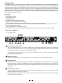
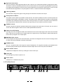
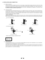
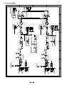
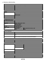
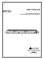
MP2D
User's Manual
TWO CHANNELS MICROPHONE /
INSTRUMENT PREAMPLIFIER WITH STEREO BUS
R
LTO
www.altoproaudio.com
Version 1.1 November 2005
English
Fuse
SAFETY RELATED SYMBOLS
To prevent fire and damage to the product, use only
the recommended fuse type as indicated in this
manual. Do not short-circuit the fuse holder. Before
replacing the fuse, make sure that the product is
OFF and disconnected from the AC outlet.
CAUTION
RISK OF ELECTRIC SHOCK
DO NOT OPEN
This symbol, wherever used, alerts you to the presence of un-insulated and dangerous voltages within the product enclosure. These are voltages that
may be sufficient to constitute the risk of electric
shock or death.
Protective Ground
Before turning the product ON, make sure that it is
connected to Ground. This is to prevent the risk of
electric shock.
This symbol, wherever used, alerts you to important operating and maintenance instructions.
Please read.
Never cut internal or external Ground wires. Likewise,
never remove Ground wiring from the Protective
Ground Terminal.
Protective Ground Terminal
Operating Conditions
AC mains (Alternating Current)
Always install in accordance with the manufacturer's
instructions.
Hazardous Live Terminal
ON:
To avoid the risk of electric shock and damage, do
not subject this product to any liquid/rain or moisture.
Do not use this product when in close proximity to
water.
Denotes the product is turned on.
OFF: Denotes the product is turned off.
WARNING
Do not install this product near any direct heat source.
Describes precautions that should be observed to
prevent the possibility of death or injury to the user.
Do not block areas of ventilation. Failure to do so
could result in fire.
CAUTION
Keep product away from naked flames.
Describes precautions that should be observed to
prevent damage to the product.
IMPORTANT SAFETY INSTRUCTIONS
Read these instructions
Disposing of this product should not be
placed in municipal waste and should be
Separate collection.
Follow all instructions
Keep these instructions. Do not discard.
Heed all warnings.
WARNING
Only use attachments/accessories specified by the
manufacturer.
Power Supply
Ensure that the mains source voltage (AC outlet)
matches the voltage rating of the product. Failure
to do so could result in damage to the product and
possibly the user.
Power Cord and Plug
Do not tamper with the power cord or plug. These are
designed for your safety.
Unplug the product before electrical storms occur
and when unused for long periods of time to reduce
the risk of electric shock or fire.
Do not remove Ground connections!
External Connection
Protect the power cord and plug from any physical
stress to avoid risk of electric shock.
If the plug does not fit your AC outlet seek advice from
a qualified electrician.
Always use proper ready-made insulated mains
cabling (power cord). Failure to do so could result
in shock/death or fire. If in doubt, seek advice from
a registered electrician.
Do not place heavy objects on the power cord. This
could cause electric shock or fire.
Cleaning
When required, either blow off dust from the product
or use a dry cloth.
Do Not Remove Any Covers
Within the product are areas where high voltages
may present. To reduce the risk of electric shock do
not remove any covers unless the AC mains power
cord is removed.
Do not use any solvents such as Benzol or Alcohol.
For safety, keep product clean and free from dust.
Servicing
Covers should be removed by qualified service
personnel only.
No user serviceable parts inside.
Refer all servicing to qualified service personnel only.
Do not perform any servicing other than those instructions contained within the User's Manual.
1
PREFACE
Thank you for choosing LTO MP2D Two Channels Microphone / Instrument Preamplifier with Stereo Bus and thanks
for choosing one of the results of LTO AUDIO TEAM job and research.
For our
LTO AUDIO TEAM, music and sound are more than a job ... is first of all passion and let us say our obsession!
We have been designing professional audio products for a long time in cooperation with some of the major brands in
the world in the audio field.
The LTO line presents unparalleled analogue and digital products made by Musicians for Musicians in our R&D centers
in Italy, Netherlands, United Kingdom and Taiwan. The core of our digital audio products is a sophisticated Software
Team for the last 7 years.
Following this idea we create our products and we will create the new ones! From our side, we guarantee you and we
will guarantee you also in future the best quality, the best fruits of our continuous researches and the best prices.
Nothing else to add, but that we would like to thank all the people that made the MP2D Two Channel Microphone /
Instrument Preamplifier with Stereo Bus, and thank our designers and all the LTO staff, people who make possible the
realization of products containing our idea of music and sound and are ready to support you, our customers, in the
best way, conscious that you are our best richness.
Thank you very much
LTO AUDIO TEAM
2
TABLE OF CONTENTS
1. INTRODUCTION..................................................................................................................................................4
2. FEATURES...................................................................................................................................... ...................4
3. CONTROL ELEMENTS......................................................................................................................................4
4. INSTALLATION AND CONNECTION....................................................................................................................7
5. BLOCK DIAGRAM..............................................................................................................................................8
6. TECHNICAL SPECIFICATION.............................................................................................................................9
7. WARRANTY.........................................................................................................................................................10
3
1. INTRODUCTION
Congratulation! Now you are the owner of the MP2D Two Channel Microphone / Instrument Preamplifier with
Stereo Bus, which is provided with 129dB of signal to noise ratio and 0.007% of THD. Each channel provides an
1/4 inch instrument socket , individual phantom power, phase reverse and high pass filter. It is equipped with a
"vintage" function to add warm, tube-like sounds to your mix. The MP2D includes a sophisticated 24 bit digital
output interface with external / internal clock and AES / EBU and S/ PDIF connectors. We believe MP2D is your
perfect choice for enhancing the performance of any console or digital audio workstation by providing two very
high-end microphone preamplifiers.
2. FEATURES
48V Phantom Power
80Hz High Pass Filter
Polarity Reverse
"Vintage" function for tube simulation
Highly accurate12 Segment Level Display
Low Impedance Stereo Mix Bus can be used for Full Control Over Stereo Imaging
Fully Loaded Back Panel Featuring XLR Balanced I/O Connectors as well as Separate Send and Return Jacks for
Inserting Dynamics Processors
Ultra high impedance 1/4" instrument input
Mix Output Connectors are XLR Balanced Providing Connectivity for Professional Recording Systems
3. CONTROL ELEMENTS
3.1 The Front Panel
4 7
9
-30 -24 -16 -8 -4 -2 0 2 4 8 16 24
CHANNEL 1
-30 -24 -16 -8 -4 -2 0 2 4 8 16 24
CHANNEL 2
OUTPUT LEVEL
ON
MASTER
OUTPUT LEVEL
0
LTO
R
INSTRUMENT
INSTRUMENT
48V
MP2D
48V
2 CHANNEL
MIC PRE-AMPLIFIER
ESOTAR
0
1
60dB
0%
L/R
100%
GAIN
VINTAGE
2
3
5
6
L
R
PAN
0
0%
60dB
GAIN
100%
VINTAGE
8
L/R
L
R
PAN
-
10dB
0
10dB
LEVEL
PHONES
POWER
10
12
11 13 14
1 1/4" Instrument Input Socket
The unit is equipped with two 1/4" instrument inputs, which have been designed to connect some instruments
such as electric guitars or basses. They are ultra high impedance amplifier designed to allow the audio potential
of an acoustic or electric instrument pickup to be fully realized.
Note: please do not use the pre-amp of the instrument on-board (if possible), in order to avoid distortion caused
by over-driving the input signal.
2 Input Gain Control
This pot can adjust the gain of the input signal. The gain range can be varied from 0dB to +60dB.
3 Vintage Control
This pot can be used to select the amount of boost (0%-100%) applied to the even harmonic series of the signal
Being amplified by a channel of the MP2D. The effect of manipulating the harmonic distortion is of increasing or
decreasing the apparent "warmth" of the signal. This capability is derived from the transformer and its dual servo
gain stage.
4
Phantom Power Switch
The unit provides +48V Phantom Power to every channel. Via this lighted switch, you can turn on /off the +48V
phantom Power for condenser microphone.
Note: please do not connect dynamic microphone when the phantom Power is on. Otherwise, It may damage
the device and the microphone.
4
5 High Pass Filter Switch
The unit provides an 80Hz high pass filter for each channel. You will activate the filter by pressing this switch.
This filter is useful for eliminating extraneous low-end information from the signal being amplified. Frequencies
from eighty hertz and below are cut from the incoming signal. But never press the switch when in music or bass
musical instrument application or the plump bass of music, or musical instrument will disappear.
6 L/R Assign Switch
This L/R button assigns the signal coming through the channel to the stereo bus output.
7 Polarity Reverse Switch
This phase reverse switch is provided for each channel. This switch enables the user to invert the phase of a
microphone when phase cancellation is noted. The phase reverse switch allows the operator to avoid phase
cancellation when identical microphones are used in close proximity to one another. The phase reverse switch also
can compensate for different XLR connector hook-ups where pin connections have been inverted.
8 PAN/BAL Control
This pot controls the channel's position between left and right in the stereo bus. Of course you can use it to
"move" the channel signal in stereo front to create spatial effects as well as.
9 Output Level LED Display
The highly accurate 12-segments LED meter indicates the level of the output signal. When these two red LEDs
flash, it will warn you that the level of output signal is too high and may cause distortion, please attenuate the
level of the input signal or the output signal.
10 MASTER LEVEL Control
This pot adjusts the output level of the Stereo Bus. Channels are assigned to the bus via the L/R assign switch
on each of the two preamplifier channels of the MP2D
11 PHONE Socket
This 1/4" socket will send out the signal to a pair of headphones. The signal monitored by the headphones is
the same signal provided by the stereo Bus to the Mix output XLR's on the rear panel of the MP2D.
12 Phone Volume Control
It adjusts the headphones volume by rotating the volume control pot.
13 Power LED
This LED lights up when the power is on.
14 Power switch.
It switches on / off MP2D main power.
AC INPUT
Use only with a 250V fuse
Apparaten skall anslutas till
jordat uttag nar den ansluts
till ett natverk
3.2 The Rear Panel
210-240V5 0Hz
Rated Power
Consumption 20W
FUSE:
250V: T315mAL
REPLACE FUSE
WITH CORRECT
TYPE ONLY
15
AES / EBU
SPDIF
16
LEFT
RIGHT
DIGITAL OUT
SAMPLING RATE
0. 44.1K
1. 48K
2
2. 88.2K
1
3
3. 96K
4. 176.4K
4
0
5. 192K
5
7
6. EXT
6
7. EXT
SEND
OUTPUT
INPUT
PUSH
SEND
OUTPUT
WCLK IN
RETURN
CH.2
MAIN OUT
17 18
19
5
RETURN
20 21
22
CH.1
23
INPUT
PUSH
15 AC Inlet
Standard IEC receptacle, connect your MP2D to mains with the supplied power cord. Before powering up your
MP2D for the first time, make certain the stated power requirement of the instrument matches the voltage supplied
in the country. Failure to do so could result in injury to the user and the probability of irreparable damage to the
unit is highly likely.
16 Digital output Connector
These connectors are professional interfaces for transmitting digital audio signal, which come configured for
AES output and SPDIF output.
17 Sample Rate Selector
The unit is provided with 6 different internal sample rates : 44.1k, 48k, 88.2 k, 96k, 176.4k, 192k, you can use this
knob to select the sample rate for the unit. Numbers 0-5 stand for internal sample rates. When you use EXT
CLOCK function, you should turn the knob to 6 or 7 position.
18 WCLK IN Connector
The WCLK IN is accessed through separate BNC connectors. The WCLK IN scans the incoming information and
automatically synchs to the necessary sample rate. If you need to use EXT CLOCK , please turn the sample rate
knob to 6 or 7 position.
19 MAIN OUTPUT
This stereo output is supplied with two XLR connectors for the RIGHT and LEFT output of the stereo main bus.
Signals are assigned to these outputs using the L / R assign switches on the individual channels.
20 SEND Connector
This 1/4 inch socket is used to sent out the signal from the MP2D to external devices such as effects or sound
processors.
21 RETURN Connector
This 1/4 inch socket is used to return the signal of external unit to the main mix. You can also use it as an extra
auxiliary input.
22 Output Connector
This XLR connector provides the analogue signal from the relevant channel to audio equipment.
23 Input Connector
This combo connector is used to input the signal.
6
4. INSTALLATION AND CONNECTION
4.1 Mains Connection
Please ensure that the MP2D is set to the correct supply voltage before plugging the power cord into the wall
outlet, use the same fuse as marked on the fuse holder at the AC power connection. The mains connection of
the MP2D is made by using the enclosed mains cord and a standard IEC receptacle. It meets all of the
international safety certification requirements.
4.2
Audio Connection
The MP2D presents with balanced XLR & 1/4" TRS and combo connectors, and it can be interfaced by
several ways to support a variety of applications without any signal loss. The MP2D can be used on a single
instrument by connecting to a mixing console's main inserts, or on an entire mix "in-line" between a mixing
console's outputs and a power amplifier.
- Wiring Configuration
Either the 1/4" TRS phone jack or the XLR connector can be wired in balanced and unbalanced modes, which
will be determined by the actual application status, please wire your system as the following wiring examples:
For 1/4" Phone jack
+
+
-
Tip
Ring
+
Tip
Tip
Ring
Sleeve
Sleeve
TS Type Unbalanced
Sleeve
TRS Type Balanced
TRS Type Unbalanced
For XLR connector
Pin2 (+)
Pin3 (-)
(Linked to Pin1 manually,
Pin2 (+)
Pin3 (-)
)
Pin1 ( )
Pin1 ( )
XLR Type Unbalanced
XLR Type Balanced
- XLR Connector Wiring For Phantom Power
PIN1 GND
PIN 2 +48v
PIN 3 +48v
4.3
Rack Mounting
The most secure mounting is on a universal rack shelf available from various rack manufactures or your music dealer.
The MP2D fits into one standard 19" rack unit of space.
Please allow at least an additional 4" depth for the connectors on the rear panel. Be sure that there is enough air
space around the unit for sufficient ventilation and please do not place the MP2D on high temperature devices such as
power amplifiers etc. to avoid overheating.
7
5. BLOCK DIAGRAM
8
6. TECHNICAL SPECIFICATION
INPUT
Connectors
XLR and 1/4" TRS (Pin 2 and Tip hot)
Type
Electronically balanced/unbalanced, RF filtered
Impedance
Balanced >50Kohm, Unbalanced>25Kohm
Max input level
CMRR
>+24dBu balanced and unbalanced
Typically>60dB at 1KHz
OUTPUT
Connectors
XLR and 1/4" TRS (Pin 2 and Tip hot)
Four balanced XLR
Type
AES/ EBU, SPDIF
Electronically balanced/unbalanced, RF filtered
Impedance
Balanced 120ohm, Unbalanced>60ohm
Max output level
>+21dBu,+20dBm balanced and unbalanced
SYSTEM SPECIFICATIONS
Bandwidth
20HZ to 20kHz, +0/-0.5dB
Frequency Response
10Hz to 200kHz,+0/-3dB
Signa/Noise
128dBu, weighted, 22Hz to 22kHz
THD
<0.007% (no vintage)
0.5% (vintage max)
Crosstalk
<-100dB, 22Hz to 22Khz
Stereo Coupling
True RMS detection
Digital
Sampling Rates
44.1k, 48k, 88.2k, 96k, 176.4k, 192k
Output
24-bit
FUNCTION SWITCHES
48 Volt Phantom Power
Each channel of the MP2D has 48V Phantom power available.
Polarity Reverse
A phase reverse switch is provided on each channel
Rumble Filter
A Rumble fiter is provided on each channel for eliminating low frequency
noise
Main L/R bus selection
The MP2D has a stereo summing bus for combining the input signals assigned
to the bus using the L/R function switch on the front panel of the MP2D
INDICATORS
INPUT LEVEL
12 element LED display: -30/-24/-16/-8/-4/-2/0/2/4/8/16/24 dB.
Function switch
LED indicator for each
POWER SUPPLY
Mains Voltages
USA/Canada
~120VAC, 60Hz
U.K./Australia
~240VAC, 50Hz
Europe
~230VAC, 50Hz
General Export Model
~100-120VAC,
~200-240VAC, 50-60Hz
Fuse
100-120VAC : 400mA (SLOW-BLOW)
200-240VAC : 200mA (SLOW-BLOW)
Power consumption
20 Watts
Mains Connection
Standard IEC receptacle
PHYSICAL
Dimension
W(483.0)*D(288.0)*H(44.2) mm
Net Weight
3.3Kg
9
7. WARRANTY
1. WARRANTY REGISTRATION CARD
To obtain Warranty Service, the buyer should first fill out and return the enclosed Warranty Registration Card within
10 days of the Purchase Date.
All the information presented in this Warranty Registration Card gives the manufacturer a better understanding of
the sales status, so as to purport a more effective and efficient after-sales warranty service.
Please fill out all the information carefully and genuinely, miswriting or absence of this card will void your warranty
service.
2. RETURN NOTICE
2.1 In case of return for any warranty service, please make sure that the product is well packed in its original shipping
carton, and it can protect your unit from any other extra damage.
2.2 Please provide a copy of your sales receipt or other proof of purchase with the returned machine , and give detail
information about your return address and contact telephone number.
2.3 A brief description of the defect will be appreciated.
2.4 Please prepay all the costs involved in the return shipping, handling and insurance.
3. TERMS AND CONDITIONS
3.1
LTO warrants that this product will be free from any defects in materials and/or workmanship for a period
of 1 year from the purchase date if you have completed the Warranty Registration Card in time.
3.2 The warranty service is only available to the original consumer, who purchased this product directly from the
retail dealer, and it can not be transferred.
3.3 During the warranty service, LTO may repair or replace this product at its own option at no charge to you for
parts or for labor in accordance with the right side of this limited warranty.
3.4 This warranty does not apply to the damages to this product that occurred as the following conditions:
Instead of operating in accordance with the user's manual thoroughly, any abuse or misuse of this product.
Normal tear and wear.
The product has been altered or modified in any way.
Damage which may have been caused either directly or indirectly by another product / force / etc.
Abnormal service or repairing by anyone other than the qualified personnel or technician.
And in such cases, all the expenses will be charged to the buyer.
3.5 In no event shall LTO be liable for any incidental or consequential damages. Some states do not allow the exclusion or limitation of incidental or consequential damages, so the above exclusion or limitation may not apply to you.
3.6 This warranty gives you the specific rights, and these rights are compatible with the state laws, you may also
have other statutory rights that may vary from state to state.
10
SEIKAKU TECHNICAL GROUP LIMITED
No. 1, Lane 17, Sec. 2, Han Shi West Road, Taichung 40151 Taiwan
http://www.altoproaudio.com Tel: 886-4-22313737
email: [email protected] Fax: 886-4-22346757
All rights reserved to ALTO. All features and content might be changed
without prior notice. Any photocopy, translation, or reproduction of part of this
manual without written permission is forbidden. Copyright c 2005 SEIKAKU GROUP
NF02205-1.1