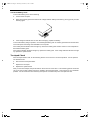
1
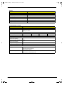
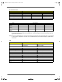
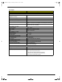
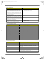
505-1.book Page I Thursday, November 4, 1999 4:36 PM
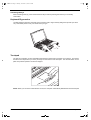
TravelMate 505
Service Guide
Service guide files and updates are available
on the AIPG/CSD web; for more information,
please refer to http://csd.acer.com.tw
PART NO.: 49.43F02.001
DOC. NO.: C4225-R01
PRINTED IN TAIWAN
505-1.book Page II Thursday, November 4, 1999 4:36 PM
Copyright
Copyright © 1999 by Acer Incorporated. All rights reserved. No part of this publication may be reproduced,
transmitted, transcribed, stored in a retrieval system, or translated into any language or computer language, in
any form or by any means, electronic, mechanical, magnetic, optical, chemical, manual or otherwise, without
the prior written permission of Acer Incorporated.
Disclaimer
The information in this guide is subject to change without notice.
Acer Incorporated makes no representations or warranties, either expressed or implied, with respect to the
contents hereof and specifically disclaims any warranties of merchantability or fitness for any particular
purpose. Any Acer Incorporated software described in this manual is sold or licensed "as is". Should the
programs prove defective following their purchase, the buyer (and not Acer Incorporated, its distributor, or its
dealer) assumes the entire cost of all necessary servicing, repair, and any incidental or consequential
damages resulting from any defect in the software.
Acer is a registered trademark of Acer Corporation.
Intel is a registered trademark of Intel Corporation.
Pentium and Pentium II/III are trademarks of Intel Corporation.
Other brand and product names are trademarks and/or registered trademarks of their respective holders.
II
505-1.book Page III Thursday, November 4, 1999 4:36 PM
Conventions
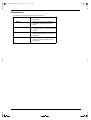
The following conventions are used in this manual:
Screen messages
Denotes actual messages that appear
on screen.
NOTE
Gives bits and pieces of additional
information related to the current
topic.
WARNING
Alerts you to any damage that might
result from doing or not doing specific
actions.
CAUTION
Gives precautionary measures to
avoid possible hardware or software
problems.
IMPORTANT
Reminds you to do specific actions
relevant to the accomplishment of
procedures.
III
505-1.book Page IV Thursday, November 4, 1999 4:36 PM
Preface
Before using this information and the product it supports, please read the following general information.
IV
1.
This Service Guide provides you with all technical information relating to the BASIC CONFIGURATION
decided for Acer's "global" product offering. To better fit local market requirements and enhance product
competitiveness, your regional office MAY have decided to extend the functionality of a machine (e.g.
add-on card, modem, or extra memory capability). These LOCALIZED FEATURES will NOT be covered
in this generic service guide. In such cases, please contact your regional offices or the responsible
personnel/channel to provide you with further technical details.
2.
Please note WHEN ORDERING FRU PARTS, that you should check the most up-to-date information
available on your regional web or channel. If, for whatever reason, a part number change is made, it will
not be noted in the printed Service Guide. For ACER-AUTHORIZED SERVICE PROVIDERS, your Acer
office may have a DIFFERENT part number code to those given in the FRU list of this printed Service
Guide. You MUST use the list provided by your regional Acer office to order FRU parts for repair and
service of customer machines.
505-1.book Page V Thursday, November 4, 1999 4:36 PM
Table of Contents
Chapter 1
System Specifications
1
Features . . . . . . . . . . . . . . . . . . . . . . . . . . . . . . . . . . . . . . . . . . . . . . . . . . . . . . . .1
Keyboard . . . . . . . . . . . . . . . . . . . . . . . . . . . . . . . . . . . . . . . . . . . . . . . . . . . .3
Keyboard Ergonomics . . . . . . . . . . . . . . . . . . . . . . . . . . . . . . . . . . . . . . . . . .6
Touchpad . . . . . . . . . . . . . . . . . . . . . . . . . . . . . . . . . . . . . . . . . . . . . . . . . . .6
System Block Diagram . . . . . . . . . . . . . . . . . . . . . . . . . . . . . . . . . . . . . . . . . . . . .8
Board Layout . . . . . . . . . . . . . . . . . . . . . . . . . . . . . . . . . . . . . . . . . . . . . . . . . . . .9
Top View . . . . . . . . . . . . . . . . . . . . . . . . . . . . . . . . . . . . . . . . . . . . . . . . . . . .9
Bottom View . . . . . . . . . . . . . . . . . . . . . . . . . . . . . . . . . . . . . . . . . . . . . . . .10
Panels . . . . . . . . . . . . . . . . . . . . . . . . . . . . . . . . . . . . . . . . . . . . . . . . . . . . . . . . .11
Front Panel . . . . . . . . . . . . . . . . . . . . . . . . . . . . . . . . . . . . . . . . . . . . . . . . .11
Rear Panel . . . . . . . . . . . . . . . . . . . . . . . . . . . . . . . . . . . . . . . . . . . . . . . . .12
Right Panel . . . . . . . . . . . . . . . . . . . . . . . . . . . . . . . . . . . . . . . . . . . . . . . . .13
Indicators . . . . . . . . . . . . . . . . . . . . . . . . . . . . . . . . . . . . . . . . . . . . . . . . . . . . . .14
Hardware Specifications and Configurations . . . . . . . . . . . . . . . . . . . . . . . . . . .15
Chapter 2
System Utilities
27
BIOS Setup Utility . . . . . . . . . . . . . . . . . . . . . . . . . . . . . . . . . . . . . . . . . . . . . . . 27
System Information . . . . . . . . . . . . . . . . . . . . . . . . . . . . . . . . . . . . . . . . . . .28
Basic System Configuration . . . . . . . . . . . . . . . . . . . . . . . . . . . . . . . . . . . .30
Startup Configuration . . . . . . . . . . . . . . . . . . . . . . . . . . . . . . . . . . . . . . . . .31
Onboard Device Configuration . . . . . . . . . . . . . . . . . . . . . . . . . . . . . . . . . .32
System Security . . . . . . . . . . . . . . . . . . . . . . . . . . . . . . . . . . . . . . . . . . . . .33
Load Default Settings . . . . . . . . . . . . . . . . . . . . . . . . . . . . . . . . . . . . . . . . .35
AFlash Utility . . . . . . . . . . . . . . . . . . . . . . . . . . . . . . . . . . . . . . . . . . . . . . . . . . . .36
Executing AFlash . . . . . . . . . . . . . . . . . . . . . . . . . . . . . . . . . . . . . . . . . . . .36
System Utility Diskette . . . . . . . . . . . . . . . . . . . . . . . . . . . . . . . . . . . . . . . . . . . .37
Panel ID Utility . . . . . . . . . . . . . . . . . . . . . . . . . . . . . . . . . . . . . . . . . . . . . .37
Thermal and Fan Utility . . . . . . . . . . . . . . . . . . . . . . . . . . . . . . . . . . . . . . . .37
Main Board Data Utility . . . . . . . . . . . . . . . . . . . . . . . . . . . . . . . . . . . . . . . .37
System Diagnostic Diskette . . . . . . . . . . . . . . . . . . . . . . . . . . . . . . . . . . . . . . . .38
Running PQA Diagnostics Program . . . . . . . . . . . . . . . . . . . . . . . . . . . . . .38
Chapter 3
Machine Disassembly and Replacement
41
General Information . . . . . . . . . . . . . . . . . . . . . . . . . . . . . . . . . . . . . . . . . . . . . .42
Before You Begin . . . . . . . . . . . . . . . . . . . . . . . . . . . . . . . . . . . . . . . . . . . .42
Connector Types . . . . . . . . . . . . . . . . . . . . . . . . . . . . . . . . . . . . . . . . . . . . .42
Disassembly Procedure Flowchart . . . . . . . . . . . . . . . . . . . . . . . . . . . . . . . . . . .43
Removing the Battery Pack . . . . . . . . . . . . . . . . . . . . . . . . . . . . . . . . . . . .45
Removing the DIMM . . . . . . . . . . . . . . . . . . . . . . . . . . . . . . . . . . . . . . . . . .45
Removing the Modem Board . . . . . . . . . . . . . . . . . . . . . . . . . . . . . . . . . . .45
Removing the Keyboard . . . . . . . . . . . . . . . . . . . . . . . . . . . . . . . . . . . . . . .46
Removing the LCD Module . . . . . . . . . . . . . . . . . . . . . . . . . . . . . . . . . . . . .47
Disassembling the LCD . . . . . . . . . . . . . . . . . . . . . . . . . . . . . . . . . . . . . . . . . . . .48
Disassembling the Main Unit . . . . . . . . . . . . . . . . . . . . . . . . . . . . . . . . . . . . . . .50
Removing the Heatsink and CPU EMI Shield . . . . . . . . . . . . . . . . . . . . . . .50
Removing the Hard Disk Drive . . . . . . . . . . . . . . . . . . . . . . . . . . . . . . . . . .50
Removing Upper Case . . . . . . . . . . . . . . . . . . . . . . . . . . . . . . . . . . . . . . . .51
Removing the Floppy Disk Drive/CD-ROM Drive Combo Module . . . . . . .51
Removing the Speakers . . . . . . . . . . . . . . . . . . . . . . . . . . . . . . . . . . . . . . .52
Removing the Audio I/O and Battery Connection Board . . . . . . . . . . . . . . .53
Removing the Fan . . . . . . . . . . . . . . . . . . . . . . . . . . . . . . . . . . . . . . . . . . . .53
Removing the Mainboard . . . . . . . . . . . . . . . . . . . . . . . . . . . . . . . . . . . . . .53
V
505-1.book Page VI Thursday, November 4, 1999 4:36 PM
Table of Contents
Removing the PCMCIA Card . . . . . . . . . . . . . . . . . . . . . . . . . . . . . . . . . . .54
Removing the Touchpad Module . . . . . . . . . . . . . . . . . . . . . . . . . . . . . . . .54
Disassembling the Hard Disk Drive Module . . . . . . . . . . . . . . . . . . . . . . . . . . . .55
Disassembling the Floppy Disk Drive and CD-ROM Combo Module . . . . . . . . .56
Chapter 4
Troubleshooting
57
System Check Procedures . . . . . . . . . . . . . . . . . . . . . . . . . . . . . . . . . . . . . . . . .58
Diskette Drive Check . . . . . . . . . . . . . . . . . . . . . . . . . . . . . . . . . . . . . . . . .58
CD-ROM Drive Check . . . . . . . . . . . . . . . . . . . . . . . . . . . . . . . . . . . . . . . . .58
Keyboard or Auxiliary Input Device Check . . . . . . . . . . . . . . . . . . . . . . . . .58
Memory Check . . . . . . . . . . . . . . . . . . . . . . . . . . . . . . . . . . . . . . . . . . . . . .59
Power System Check . . . . . . . . . . . . . . . . . . . . . . . . . . . . . . . . . . . . . . . . .59
Touchpad Check . . . . . . . . . . . . . . . . . . . . . . . . . . . . . . . . . . . . . . . . . . . . .60
Index of Error Message . . . . . . . . . . . . . . . . . . . . . . . . . . . . . . . . . . . . . . . . . . .61
Index of Symptom-to-FRU Error Message . . . . . . . . . . . . . . . . . . . . . . . . . . . . .64
Intermittent Problems . . . . . . . . . . . . . . . . . . . . . . . . . . . . . . . . . . . . . . . . . . . . .68
Undetermined Problems . . . . . . . . . . . . . . . . . . . . . . . . . . . . . . . . . . . . . . . . . . .69
Index of PQA Diagnostic Error Code, Message . . . . . . . . . . . . . . . . . . . . . . . . .70
Chapter 5
Jumper and Connector Locations
71
Top View . . . . . . . . . . . . . . . . . . . . . . . . . . . . . . . . . . . . . . . . . . . . . . . . . . . . . . .71
Bottom View . . . . . . . . . . . . . . . . . . . . . . . . . . . . . . . . . . . . . . . . . . . . . . . . . . . .72
Chapter 6
FRU (Field Replaceable Unit) List
73
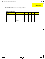
Appendix A
Model Definition and Configuration
87
Appendix B
Test Compatible Components
89
Microsoft Windows 98 ACPI Environment Test . . . . . . . . . . . . . . . . . . . . . . . . .90
Appendix C
Index
VI
Online Support Information
93
95
505-1.book Page 1 Thursday, November 4, 1999 4:36 PM
Chapter 1
System Specifications
Features
This computer was designed with the user in mind. Here are just a few of its many features:
Performance
Intel® Celeron™ processor with 128 KB level 2 cache
64-bit/128-bit main memory
Large LCD display and PCI video with 128-bit graphics acceleration
Internal CD-ROM drive
Built-in FDD module
High-capacity, Enhanced-IDE hard disk
NiMH battery pack
Power management system with hibernation power saving modes
Multimedia
16-bit high-fidelity stereo audio with 3D sound and wavetable synthesizer
Built-in dual speakers
Ultra-slim, high-speed CD-ROM drive
Connectivity
High-speed fax/data modem port
USB (Universal Serial Bus) port
Human-centric Design and Ergonomics
All-in-one design (CD-ROM, FDD, HDD)
Sleek, smooth and stylish design
Full-sized keyboard
Wide and curved palm rest
Ergonomically-centered touchpad pointing device
Expansion
Chapter 1
CardBus PC card (formerly PCMCIA) slots (two type II/I or one type III), with ZV (Zoomed Video)
port support
Upgradeable memory and hard disk
1
505-1.book Page 2 Thursday, November 4, 1999 4:36 PM
Display
The large graphics display offers excellent viewing, display quality and desktop performance graphics. The
computer supports two different display configurations — High Performance Addressing (HPA) or Thin-Film
Transistor (TFT).
Video Performance
PCI video with 128-bit graphics acceleration and 2 MB video memory boost video performance.
Simultaneous Display
The computer’s large display and multimedia capabilities are great for giving presentations. If you prefer, you
can also connect an external monitor when giving presentations. This computer supports simultaneous LCD
and CRT display. Simultaneous display allows you to control the presentation from your computer and at the
same time face your audience. You can also connect other output display devices such as LCD projection
panels for large-audience presentations.
Power Management
The power management system incorporates an “automatic LCD dim” feature that automatically dims the LCD
when the computer is powered by a battery pack to conserve battery power. See “Power Management” for
more information on power management features.
Opening and Closing the Display
To open the display, slide the display cover latch to the left and lift up the cover. Then tilt it to a comfortable
viewing position. The computer employs a microswitch that turns off the display (and enters standby mode) to
conserve power when you close the display cover and turns it back on when you open the display cover.
NOTE: If an external monitor is connected, the computer turns off the display (but does not enter standby
mode) when you close the display cover.
To close the display cover, fold it down gently until the display cover latch clicks into place.
CAUTION: To avoid damaging the display, do not slam it when you close it. Also, do not place any object on
top of the computer when the display is closed.
2
Chapter 1
505-1.book Page 3 Thursday, November 4, 1999 4:36 PM
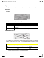
Keyboard
The keyboard has full-sized keys and an embedded keypad, separate cursor keys, two Windows keys and
twelve function keys.
Special Keys
Lock Keys
The keyboard has three lock keys which you can toggle on and off.
Lock Key
Description
Caps Lock
When Caps Lock is on, all alphabetic characters typed are in uppercase.
Num Lock (Fn-F11)
When Num Lock is on, the embedded keypad is in numeric mode. The keys function as
a calculator (complete with the arithmetic operators +, -, *, and /). Use this mode when
you need to do a lot of numeric data entry. A better solution would be to connect an
external keypad.
Scroll Lock (Fn-F12)
When Scroll Lock is on, the screen moves one line up or down when you press ↑ or ↓
respectively. Scroll Lock does not work with some applications.
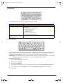
Embedded Numeric Keypad
The embedded numeric keypad functions like a desktop numeric keypad. It is indicated by small characters
located on the upper right corner of the keycaps. To simplify the keyboard legend, cursor-control key symbols
are not printed on the keys.
Desired Access
Num Lock On
Num Lock Off
Number keys on embedded keypad
Type numbers in a normal manner.
Cursor-control keys on embedded
keypad
Hold Shift while using cursor-control keys.
Hold Fn while using cursorcontrol keys.
Main keyboard keys
Hold Fn while typing letters on embedded
keypad.
Type the letters in a normal
manner.
NOTE: If an external keyboard or keypad is connected to the computer, the NumLock feature automatically
shifts from the internal keyboard to the external keyboard or keypad.
Chapter 1
3
505-1.book Page 4 Thursday, November 4, 1999 4:36 PM
Windows Keys
The keyboard has two keys that perform Windows-specific functions.
Key
Windows logo key
Description
Start button. Combinations with this key perform special functions. Below are a
few examples:
+ Tab (Activates next Taskbar button)
+ E (Explores My Computer)
+ F (Finds Document)
+ M (Minimizes All)
Shift + + M (Undo Minimize All)
+ R (Displays the Run dialog box)
Application key
Opens the application’s context menu (same as right-click).
(Fn-Application key)
The Euro Symbol
If your keyboard is in any of the following languages -- United States-International, United Kingdom, French,
German, Italian, Spanish, Portuguese, Danish, Swiss German, Swiss French, Czech, Belgian, Norwegian,
Hungarian, Turkish, Swedish or Finnish -- you can type the Euro symbol on your keyboard.
IMPORTANT:(for US keyboard users): The keyboard type is set when you first set up Windows. For the Euro
symbol to work, the keyboard type has to be set to United States-International.
To verify the keyboard type:
4
1.
Click on Start, Settings, Control Panel.
2.
Double-click on Keyboard.
3.
Click on the Language tab.
4.
Verify that the keyboard type used for "English (United States)" is set to United States-International.
5.
If not, select and click on Properties; then select United Stated-International and click on OK.
6.
Click on OK.
Chapter 1
505-1.book Page 5 Thursday, November 4, 1999 4:36 PM
To type the Euro symbol:
1.
Locate the Euro symbol on your keyboard.
2.
Open a text editor or word processor.
3. Hold Alt Gr and press the Euro symbol.
NOTE: The Alt Gr is only used together with the Euro symbol. Some fonts and software do not support the
Euro symbol. Please refer to http://www.microsoft.com/typography/faq/faq12.htm for more
information.
Hot Keys
The computer employs hot keys or key combinations to access most of the computer’s controls like screen
contrast and brightness, volume output and the BIOS setup utility
Hot Key
Icon
Function
Description
Fn-F1
Hotkey help
Displays a list of the hotkeys and their functions.
Fn-F2
Setup
Accesses the notebook configuration utility.
Fn-F3
Power Scheme Toggle
Switch between the different Power Management
schemes.
Fn-F4
Sleep
Puts the computer in Sleep mode, which can be defined
via the advanced section of the Power Management
Properties in the Windows Control Panel.
Fn-F5
Display toggle
Switches display output between the display screen,
external monitor (if connected) and both the display
screen and external monitor.
Fn-F6
Screen blank
Turns the display screen backlight off to save power.
Press any key to return.
Fn-F7
Touchpad on/off
Turns the internal touchpad on and off.
When you connect an external PS/2 mouse, the
computer automatically disables the touchpad.
Fn-F8
Speaker on/off
Turns the speakers on and off; mutes the sound.
Fn-↑
Contrast up
Increases the screen contrast (available only for models
with HPA displays).
Fn-↓
Contrast down
Decreases the screen contrast (available only for models
with HPA displays).
Fn-→
Brightness up
Increases the screen brightness.
Fn-←
Brightness down
Decreases the screen brightness.
Chapter 1
5
505-1.book Page 6 Thursday, November 4, 1999 4:36 PM
Activating Hotkeys
When activating hotkeys, press and hold the first key Fn before pressing the other key in the hotkey
combination.
Keyboard Ergonomics
Located below the keyboard, the wide and curved palm rest is ergonomically designed to provide you with a
very comfortable place to rest your hands while you type.
Touchpad
The built-in touchpad is a PS/2-compatible pointing device that senses movement on its surface. This means
that the cursor responds as you move your finger on the surface of the touchpad. The central location on the
palm rest provides optimum comfort and support.
NOTE: When you connect an external PS/2 mouse, the computer automatically disables the internal touchpad.
6
Chapter 1
505-1.book Page 7 Thursday, November 4, 1999 4:36 PM
Touchpad Basics
The following items teach you how to use the touchpad:
1.
Move your finger across the touchpad to move the cursor.
2.
Press the left and right buttons located on the edge of the touchpad to do selection and execution
functions. These two buttons are similar to the left and right buttons on a mouse. Tapping on the
touchpad produces similar results.
Function
Left Button
Right Button
Tap
Execute
Click twice quickly
Tap twice (at the same speed as double-clicking
the mouse button).
Select
Click once
Tap once
Drag
Click and hold, then
use finger to drag the
cursor on the
touchpad.
Tap twice (at the same speed as double-clicking
the mouse button) and hold finger to the touchpad
on the second tap to drag the cursor.
Access context
menu
Click once
NOTE: Keep your fingers dry and clean when using the touchpad. Also keep the touchpad dry and clean. The
touchpad is sensitive to finger movements. Hence, the lighter the touch, the better the response.
Tapping too hard will not increase the touchpad’s responsiveness.
Chapter 1
7
505-1.book Page 8 Thursday, November 4, 1999 4:36 PM
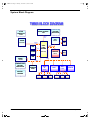
System Block Diagram
TM505 BLOCK DIAGRAM
MOBILE CELERON
CPU
CLOCK
GENERATOR
CPU CORE
REGULATOR
CY2272
HOST Bus
66 MHz
CRT
VGA
SDRAM
NM2160
32MB/ 64MB
LCD
SDRAMBus
66 MHz
HDD
IDE BUS
CDROM
CORE
LOGIC
82440MX
PCI BUS
33 MHz
CARDBUS
(BANISTER)
OZ6812
AUDIO/ BATTERY
BOARD
CS4299
POWER & DC-DC
VOLTAGE
REGULATORS
CARDBUS
SLOT
USB
X-BUS
AC-LINK
MODEM
DAUGHTER
CARD
S I/O
Ali
BIOS
5135B
KBC
M38867
PORT 80
BATTERY
CHARGER
PRINTER
8
FLOPPY
SERIAL
TOUCHPAD
INT. KB
EXT. KB
Chapter 1
505-1.book Page 9 Thursday, November 4, 1999 4:36 PM
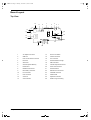
Board Layout
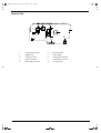
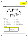
Top View
12
11
7
5
8
4
6
13
14
1
2
3
26
10 9
25
24
15
16
21
23
22
19
17
Chapter 1
20
18
1
AC Adapter Connector
14
Power Push Switch
2
USB Port
15
Celeron Processor
3
LCD Corner Switch Connector
16
Fan Connector
4
PS/2 Port
17
Onboard DC/DC Charger
5
Serial Port
18
HDD Connector
6
Onboard System Memory
19
Internal Keyboard Connector
7
Parallel Port
20
Touch Pad Connector
8
LED Board Connector
21
Onboard Switch
9
RTC Battery Connector
22
Diskette Drive Connector
10
Fan Connector
23
CD-ROM Connector
11
LCD Connector
24
PCMCIA Slot
12
VGA Port
25
Keyboard Controller
13
VGA Controller
26
Golden Finger for Debug
9
505-1.book Page 10 Thursday, November 4, 1999 4:36 PM
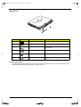
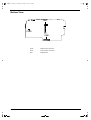
Bottom View
4
3
2
1
6
5
7
10
8
10
9
1
Intel FW 82443 Chipset
6
BIOS Flash ROM
2
DIMM Socket
7
Audio CODEC
3
CardBus Controller
8
Onboard System Memory
4
Super I/O Controller
9
Audio/Battery Connector
5
Modem Board Connector
10
Clock Generator
Chapter 1
505-1.book Page 11 Thursday, November 4, 1999 4:36 PM
Panels
Ports allow you to connect peripheral devices to your computer as you would with a desktop PC.
NOTE: See chapter 3 on how to connect external devices to the computer.
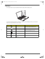
Front Panel
The front panel contains ports for external audio connections.
#
Icon
Port
Connects to...
1
Speaker-out jack
Speakers or headphones
2
Audio line-in jack
Audio line-in device with a 3.5mm minijack (e.g.,
audio CD player, stereo walkman)
3
Microphone-in jack
3.5mm minijack condenser microphone
Chapter 1
11
505-1.book Page 12 Thursday, November 4, 1999 4:36 PM
Rear Panel
#
Icon
Port
Connects to...
1
DC-in jack
AC adapter and power outlet
2
USB port
USB devices (e.g., USB mouse)
3
PS/2 port
PS/2-compatible devices (e.g., PS/2 keyboard/
mouse/keypad)
4
Serial port
Serial devices (e.g., serial mouse)
5
Parallel port
Parallel devices (e.g., parallel printer)
6
External monitor port
Display monitor (up to 1024x768 resolution, 64Kcolors)
Universal Serial Bus
The Universal Serial Bus (USB) port is a high-speed serial bus which allows you to connect and daisy-chain
USB peripherals without taking up precious system resources.
12
Chapter 1
505-1.book Page 13 Thursday, November 4, 1999 4:36 PM
Right Panel
#
Icon
Port
Connects to...
1
PC Card slot
16-bit PC Cards and 32-bit CardBus PC Cards (ZV
support)
2
Modem jack
Phone line (only for models with an internal fax
modem)
Chapter 1
13
505-1.book Page 14 Thursday, November 4, 1999 4:36 PM
Indicators
The computer has six easy-to-read status indicators (LEDs) under the display screen.
The Power and Standby indicators are visible even when you close the display cover so you can see the
status of the computer while the cover is closed.
#
1
Icon
Function
Power
Description
Lights when the computer is on.
Blinks when a battery-low condition occurs.
2
Standby
Lights when the computer enters Standby mode.
3
Media Activity
Lights when the floppy drive, hard disk or CDROM drive or DVD-ROM drive is active.
4
Battery Charge
Lights when the battery is being charged.
5
Caps Lock
Lights when Caps Lock is activated.
6
Num Lock
Lights when Numeric Lock is activated.
(Fn-F11)
14
Chapter 1
505-1.book Page 15 Thursday, November 4, 1999 4:36 PM
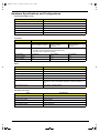
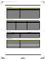
Hardware Specifications and Configurations
System Board Major Chips
Item
Controller
System Core Logic
Intel 82440 MX (Banister)
Super I/O Controller
ALI 5135B
Keyboard Controller
Mitsubishi M38867 V JG TQ FP
Audio Controller
Intel 82440 MX (Banister)
PCMCIA Controller
O2 OZ6812
VGA Controller
NeoMagic NM2160
Processor
Item
Specification
CPU Type
Intel Mobile
Celeron-400 MHz Processor
Intel Mobile
Celeron-433 MHz
Processor
CPU Specification
1. Integrated primary L1 instruction and data cache
Intel Mobile
Celeron-466 MHz
Processor
2. 128-Kbyte L2 cache integrated onto the processor die
3. Low power GTL+ system bus interface
CPU Package
BGA package
BGA package
BGA package
CPU Core Voltage
1.6 V
1.9 V
1.9 V
CPU I/O Voltage
2.5 V
2.5 V
2.5 V
BIOS
Item
Specification
BIOS vendor
Acer
BIOS Version
V3.0
BIOS ROM type
Flash ROM
BIOS ROM size
256KB
BIOS package
32-pin TSOP
Supports protocol
PCI 2.1, SMI & APM 1.2, DMI 2.00.1, E-IDE, ACPI, USB, ESCD 1.03,
ANSI ATA 3.0, PnP 1.0a, Bootable CD-ROM 1.0, ATAPI, ECP/EPP 1.7
& 1.9
BIOS password control
Set by switch, see SW4 settings
Second-Level Cache
Item
Cache controller
Specification
Intel 82440 MX (Banister)
Cache size
128 KB (Celeron CPU type)
1st level cache control
Always enabled
2nd level cache control
Always enabled
Cache scheme control
Fixed in write-back
Chapter 1
15
505-1.book Page 16 Thursday, November 4, 1999 4:36 PM
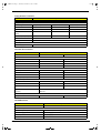
System Memory
Item
Specification
Memory controller
Intel Banister 82440 MX
Onboard memory size
32/64 MB
DIMM socket
1
Supported memory size per socket
32/64/128 MB
Supported maximum memory size
192 MB (64 MB + 128 MB)
Supported DIMM type
Synchronous DRAM
Supported DIMM speed
66 MHz
Supported DIMM voltage
3.3V
Supported DIMM package
144-pin so-DIMM
Memory Combinations
On Board
Slot 1
Total Memory
32 MB
0 MB
32 MB
32 MB
32 MB
64 MB
32 MB
64 MB
96 MB
32 MB
128 MB
160 MB
64 MB
0 MB
64 MB
64 MB
32 MB
96 MB
64 MB
64 MB
128 MB
64 MB
128 MB
192 MB
LAN Interface
Item
Specification
LAN Controller
None
LAN Controller Resident Bus
None
LAN Port
None
Function Control
None
MODEM Interface
Item
16
Specification
Chipset
Lucent 1646
Fax modem data baud rate (bps)
14.4 K
Data modem data baud rate (bps)
56 K
Supported modem protocol
V.90 data modem, V.17 fax modem, and digital line protection
operation
Modem connector type
RJ45 (Capable of RJ11)
Modem connector location
Right side
Chapter 1
505-1.book Page 17 Thursday, November 4, 1999 4:36 PM
Floppy Disk Drive Interface
Item
Specification
Vendor & model name
Mitsumi D353F3X
Floppy Disk Specifications
Media recognition
2DD (720KB)
2HD (1.2MB, 3-mode)
2HD (1.44MB)
Sectors/track
9
15
18
Tracks
80
80
80
Data transfer rate
(Kbit/s)
1 MB
1.6 MB
2 MB
Rotational speed (RPM)
300
360
300
Read/write heads
2
Encoding method
MFM/FM
Power Requirement
Input Voltage (V)
+5V ±10%
Hard Disk Drive Interface
Item
Vendor & Model Name
Specification
IBM DARA 206000
IBM DARA 209000
Capacity (MB)
6000
9000
Bytes Per Sector
512
512
Logical Heads
15
16
Logical Sectors
63
63
Logical Cylinders
12416
16383
Physical Read/Write Heads
2
3
Disks
1
2
Spindle Speed (RPM)
4200
4200
Drive Format
Drive Format
Performance Specifications
Buffer Size
418 KB
418 KB
Interface
IDE
IDE
Data Transfer Rate (Disk-Buffer, Mbits/
s)
161.6 - 85.5
161.6 - 85.5
Data Transfer Rate (Host-Buffer,
Mbytes/s)
66.6 max
16.6 max
DC Power Requirements
Voltage Tolerance
5V +/- 5%
5V +/- 5%
CD-ROM Interface
Item
Vendor & Model Name
Specification
TEAC CD-224E-A26 24X
Performance Specification
Transfer rate (KB/sec)
1545KB/sec ~ 3,600KB/sec (FULL - CAV)
Access time (typ.)
130 msec. (typ.)
Rotation speed
5136 rpm (typ.)
Memory Buffer
None
Chapter 1
17
505-1.book Page 18 Thursday, November 4, 1999 4:36 PM
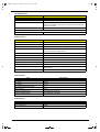
CD-ROM Interface
Item
Specification
Data Buffer
128 KB
Interface
ATAPI
Applicable disc format
CD-DA, CD-ROM (Mode-1, Mode-2), CD-ROM XA MODE-2 (FORM-1,
FORM-2), Multi-Session Photo CD, CD-I, Video CD, Enhanced CD &
CD PLUS Compatible
Loading mechanism
Drawer with soft eject and emergency eject hole
Power Requirement
Input Voltage
5V +/- 5%
Audio Interface
Item
Specification
Audio Controller
Intel 82440 MX (Banister)/Cirrus Logic CS4229
Audio onboard or optional
Built-in
Mono or Stereo
Stereo
Resolution
20 bit stereo Digital to Analog converter
18 bit stereo Analog to Digital converter
Compatibility
PC ‘98, PC ‘99, AC97 2.1
Mixed sound source
Line-in, CD, Video, AUX
Voice channel
8-/16-bit, mono/stereo
Sampling rate
44.1 KHz
Internal microphone
None
Internal speaker/quantity
Yes/2 pieces, on two sides of front panel
Supported PnP DMA channel
DMA channel 0
DMA channel 1
Supported PnP IRQ
IRQ11
Video Interface
Item
Specification
Chip vendor
NeoMagic
Chip name
NM2160
Chip voltage
3.3 volts
Supports ZV (Zoomed Video) port
Yes
Graph interface
PCI bus
Maximum resolution (LCD)
800 x 600 (True color/24 bit)
Maximum resolution (CRT)
1024 x 768 (High color/16bit)
Video Memory
Item
18
Specification
Fixed
Fixed, built-in NM2160 video controller
Video memory size
2.0 MB
Chapter 1
505-1.book Page 19 Thursday, November 4, 1999 4:36 PM
Video Resolution Modes
Resolution
Refresh Rate
CRT Only
LCD/CRT Simultaneous
640x480x256
75
60
640x480x64K
75
60
640x480x16M
75
60
800x600x256
75
60
800X600X64K
75
60
800X600X16M
75
60
1024x768x256
75
60
1024x768x64K
75
60
1024x768x16M
75
60
Parallel Port
Item
Specification
Parallel port controller
ALI 5135B
Number of parallel port
1
Location
Rear side
Connector type
25-pin D-type connector, in female type
Parallel port function control
Enable/Disable by BIOS Setup
Supports ECP
Yes (set by BIOS setup)
Optional ECP DMA channel
(in BIOS Setup)
DMA channel 1
DMA channel 3
Optional parallel port I/O address
(in BIOS Setup)
3BCh, 378h, 278h
Optional parallel port IRQ
(in BIOS Setup)
IRQ7
Serial Port
Item
Serial port controller
Specification
ALI 5135B
Number of serial port
1
Supports 16550 UART
Yes
Connector type
9-pin D-type connector, in male type
Location
Rear side
Serial port function control
Enable/disable by BIOS Setup
Optional serial port
(in BIOS Setup)
3F8h, 2F8h, 3E8h, 2E8h,
Optional serial port IRQ
(in BIOS Setup)
IRQ4, IRQ3
Chapter 1
19
505-1.book Page 20 Thursday, November 4, 1999 4:36 PM
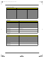
USB Port
Item
Specification
HCl
UHCl 1.0
Number of USB Port
1
Location
Rear Side
Serial Port Function Control
Enable / Disable by BIOS Stup
IrDA Port
Item
Specification
Vendor & Model Name
None
Input Power Supply Voltage
None
Transfer Data Rate
None
Transfer Distance
None
Compatible Standard
None
Output Radiant Intensity Half Angle
None
Number of IrDA Port
None
16550 UART Support
None
FIR Location
None
Selection Serial Port (by BIOS Setup)
None
PCMCIA Port
Item
Specification
PCMCIA controller
O2 OZ6912
Supported card type
Type-II/ Type-III
Number of slots
One type-II or one type-III
Access location
Right side
Supported ZV (Zoomed Video) port
Yes
Supported 32 bit CardBus
Yes (IRQ9)
Keyboard
Item
20
Specification
Keyboard controller
Mitsubishi M38867 VJG TQFP
Keyboard vendor & model name
API
Total number of keypads
84-/85-/88-key
Windows 95 keys
Yes
Internal & external keyboard work
simultaneously
Yes
Chapter 1
505-1.book Page 21 Thursday, November 4, 1999 4:36 PM
Battery
Item
Specification
Vendor & model name
Panasonic BTP-1831
Battery Type
NiMH
Pack capacity
3500 mAH
Cell voltage
1.2V
Number of battery cell
8
Package configuration
8S
Package voltage
9.6V
DC-DC/Charger Converter
Item
Vendor & Model Name
Input voltage
Specification
Acer
AC adapter: 19V-21V
Battery: 12V-16.8V
DC/DC converter output
Output Rating
5V
3.3V
12V
5V SB
Current (w/load, A)
0~2
0~3.5
0~0.25
0.02
Charger output
Normal charge (charge while
system is not operative)
2.2A
Background charge (charge even
system is still operative)
0.8A
Battery-low 2 level (V)
8.8V
Battery-low 3 level (V)
8V
Protection
Charger protection
Security timer control
Over temperature protection
Over voltage protection
DC/DC converter protection
OVP (Over Voltage Protection, V)
OCP (Over Current Protection, A)
Chapter 1
21
505-1.book Page 22 Thursday, November 4, 1999 4:36 PM
DC-AC LCD Inverter
Item
Specification
Vendor & Model Name
Ambit T62.121.C.00 (12.1”)
Input Voltage (V)
7.3 (min.)
None
22 (max.)
Input Current (mA)
None
None
1000 (max.)
Output Voltage (Vrms, no load)
1100 (min.)
None
1400 (max.)
Output Voltage Frequency (KHz)
40 (min.)
None
65 (max.)
Item
Specification
Output Current
(mArms)
Min.
Typ.
Max.
Remark
Output Current
(mArms)
6.3
7.0
7.7
Vadj : 3.2 V
Output Current
(mArms)
0.7
1.0
1.3
Vadj : 2.15 V
NOTE: DC-AC inverter is used to generate very high AC voltage, to support LCD CCFT backlight user, and it is
also responsible for the control of LCD brightness. Avoid touching the DC-AC inverter area while the
system unit is turned on.
NOTE: There is an EEPROM in the inverter, which stores its supported LCD type and ID code. If you replace
a new inverter or replace the LCD with one of a different brand, use Inverter ID utility to update the ID
information.
LCD
Item
Vendor & model name
Specification
12.1" Sharp
12.1” Hitachi
LM121SS1T53
TX31D27VCICBB
12.1
12.1
Mechanical Specifications
LCD display area (diagonal, inch)
Display technology
DSTN
TFT
Resolution
SVGA (800x600)
SVGA (800x600)
Supports colors
16 M
16 M
Brightness control
Keyboard hotkey
Keyboard hotkey
Contrast control
Keyboard hotkey
None
Optical Specifications
Electrical Specifications
22
Supply voltage for LCD display (V) 3.3 (typ.)
3.3 (typ.)
Supply voltage for LCD backlight
(Vrms)
650 (typ)
650 (typ)
Chapter 1
505-1.book Page 23 Thursday, November 4, 1999 4:36 PM
AC Adapter
Item
Vendor & Model Name
Specification
Delta ADP-60XBVD
Input Requirements
Maximum Input Current
(A, @90Vac, full load)
1A @ 90 Vac
Nominal Frequency (Hz)
47 - 63
Frequency Variation Range (Hz)
47 - 63
Nominal Voltages (Vrms)
90 - 270
Inrush Current
The maximum inrush current will be less than 50A and 100A when the
adapter is connected to 115Vac(60Hz) and 230Vac(50Hz) respectively.
Efficiency
It should provide an efficiency of 83% minimum, when measured at
maximum load under 115V(60Hz).
Output Ratings (CV mode)
DC Output Voltage
+19.0V - 20.5V
Noise + Ripple
300mvp-pmax (20MHz bandwidth)
Load
0A (min.) 2.4A (max.)
Output Ratings (CC mode)
DC Output Voltage
20V +/- 1.0V
Constant Output
3.6 +/- 0.3A
Dynamic Output Characteristics
Turn-on Delay Time
2 sec. (@115Vac)
Hold Up Time
8 ms min. (@115Vac input, full load)
Over Voltage Protection (OVP)
24 V
Short Circuit Protection
Output can be shorted without damage
Electrostatic Discharge (ESD)
15kV (at air discharge)
8kV (at contact discharge)
Dielectric Withstand Voltage
Primary to Secondary
1500Vac (or 2121 Vdc) for 1 second
Leakage Current
0.25 mA max. (@ 254 Vac, 60Hz)
Regulatory Requirements
Internal filter meets:
1. FCC class B requirements (USA)
2. VDE 243/1991 class B requirements (German)
3. CISPR 22 Class B requirements (Scandinavia)
4. VCCI class II requirements (Japan)
Chapter 1
23
505-1.book Page 24 Thursday, November 4, 1999 4:36 PM
Power Management
Power Saving Mode
Standby Mode
Waiting time specified by the System Standby value or the
operating system elapses without any system activity.
Phenomenon
The buzzer beeps
The Standby indicator lights up
Or
When the computer is about to enter Hibernation mode
(e.g., during a battery-low condition), but the Hibernation
file is invalid or not present.
Hibernation Mode
When customized functions for power management are
set to Hibernation and the corresponding action is taken.
Display Standby Mode
Keyboard, built-in touchpad, and an external PS/2 pointing
device are idle for a specified period.
Hard Disk Standby Mode
All power shuts off
The display shuts off
Hard disk is idle within a specified period of time.
Hard disk drive is in standby mode.
(spindle turned-off)
Environmental Requirements
Item
Specification
Temperature
Operating
+5 ~ +35 Degree C
Non-Operating
-20 ~ + 60 Degree C
Humidity
Operating
20% ~ 80% RH, Non-condensing
Non-Operating
20% ~ 90% RH, Non-condensing
Vibration
Operating (Unpacked)
5 ~ 25.6 Hz,
0.38 mm
5 ~ 27.1 Hz,
0.6G
27.1 ~ 50 Hz,
0.41 mm
50 ~ 500 Hz,
2G
Non-Operating
Unpacked
Packed
5 ~ 62.6 Hz,
62.6 ~ 500 Hz,
0.51 mm
4G
Mechanical Specifications
Item
24
Specification
Dimensions
308mm x 257mm x 44.7mm
Weight
7lbs (Battery included)
I/O Ports
Mouse, 1 Parallel, 1 Serial, 1 USB, 1 Modem Jack,
1 PCMCIA Slot, 1 VGA Port, 1 Microphone Jack, 1 Line-in Jack, 1
Line-out Jack
Drive Bays
One 3.5” FDD, One CD-ROM
Material
Plastic
Indications
Power Light, Sleep Mode Light, Media Activity Light, Battery Charge
Light, Caps Lock Light, Numbers Lock Light
Switch
Power
Chapter 1
505-1.book Page 25 Thursday, November 4, 1999 4:36 PM
Memory Address Map
Memory Address
Size
Function
00000000-0009FFFF
640 KB
Base memory
000A0000-000BFFFF
128 KB
Video memory
000C0000-000CBFFF
40 KB
Video BIOS
000E0000-000FFFFF
128 KB
System BIOS
00100000-top limited
--
Extended (DIMM) memory
04000000-04000FFF
4 KB
PCMCIA controller (slot 1)
04001000-04001FFF
4 KB
PCMCIA controller (slot 2)
80100000-801000FF
256 B
Lucent Win Modem
80500000-805FFFFF
1 MB
NetMagic VGA
80800000-80BFFFFF
3 MB
Neomagic VGA
81000000-81FFFFFF
16 MB
82100000-82100FFF
4 MB
FFFF0000-FFFFFFFF
64 KB
System board extension for PnP BIOS
I/O Address Map
I/O Address
Function
000-00F
DMA controller-1
020-021
Interrupt controller-1
040-043
Timer 1
060, 064
Keyboard controller 8742 chip select
061
System speaker out
040B
DMA controller-1
061
System speaker
070-071
Real-time clock and NMI mask
080-08F
DMA page register
0A0-0A1
Interrupt controller-2
0C0-0DF
DMA controller-2
0F0-0FF
Numeric data processor
120-13F, 180-18F
Power management controller
170-177
2nd EIDE device (CD-ROM) select
1F0-1F7
1st EIDE device (hard drive) select
220-22F
Audio
240-24F
Audio(optional)
278-27F
Parallel port 3
2E8-2EF
LT Win modem or COM4 (optional)
2F8-2FF
COM2 or LT Win modem(optional)
378, 37A
Parallel port 2
3BC-3BE
Parallel port 1
3B0-3BB, 3C0-3DF
Video Controller
3F0h-3F7
Standard Floppy Disk Controller
3E8-3EF
COM3 or LT Win modem (optional)
3F0-3F7
Floppy disk controller
3F8-3FF
COM1 or LT Win modem (optional)
480-48F, 4D6
DMA controller-1
4D0-4D1, CF8-CFF
PCI configuration register
Chapter 1
25
505-1.book Page 26 Thursday, November 4, 1999 4:36 PM
IRQ Assignment Map
Interrupt Channel
NMI
Function
System errors
IRQ0
System timer
IRQ1
Keyboard
IRQ2
Cascade
IRQ3
COM2
IRQ4
COM1
IRQ5
VGA
IRQ6
Floppy
IRQ7
LPT1
IRQ8
Real time clock
IRQ9
PCMCIA (Optional)
IRQ10
USB
IRQ11
Audio/Modem/CardBus
IRQ12
PS2 pointing device
IRQ13
Numeric data processor
IRQ14
1st IDE device (hard disk)
2nd EIDE device (CD-ROM drive)
IRQ15
Optional
DMA Channel Assignment
DMA Channel
26
Function
DRQ0
Audio (optional)
DRQ1
ECP or Audio (optional)
DRQ2
Floppy
DRQ3
ECP (optional)
DRQ4
DMA controller
DRQ5
Not used
DRQ6
Not used
DRQ7
Not used
Chapter 1
505-1.book Page 27 Thursday, November 4, 1999 4:36 PM
Chapter 2
System Utilities
BIOS Setup Utility
The BIOS Setup Utility is a hardware configuration program built into your computer’s BIOS (Basic Input/
Ouput System).
Your computer is already configured and optimized properly, and you do not need to run this utility. However,
if you encounter configuration problems, you may need to run it.
To activate the BIOS Setup Utility, press F2 during POST while the TravelMate logo is being displayed.
Navigating the BIOS Setup Utility
There are six menu options: System Information, Basic System Settings, Startup Configuration, Onboard
Device Configuration, System Security and Load Default Settings.
To enter a menu, highlight the item using the ↑ ↓ keys; then press Enter.
Within a menu, navigate through the BIOS Setup Utility by following these instructions:
Press the cursor up/down keys (↑↓) to move between parameters.
Press the cursor left/right keys (→ ←) to change the value of a parameter.
Press Esc while you are in any of the menu options to return to the main menu
NOTE: You can change the value of a parameter if it is enclosed in square brackets.
NOTE: Navigation keys for a particular menu are shown at the bottom of the screen.
Chapter 2
27
505-1.book Page 28 Thursday, November 4, 1999 4:36 PM
System Information
The System Information screen displays a summary of your computer hardware information.
The table below describes the parameters in this screen.
Parameter
Description
CPU Type & Speed
Describes the type of CPU installed in the system.
Floppy Disk Drive
Shows the floppy disk drive type (1.44MB 3.5-inch).
Hard Disk (MB)
Sets the hard disk type.
HDD Serial Number
Shows the hard disk drive serial number.
System with
Shows the high-capacity disc drive installed.
System BIOS Version
Shows the system BIOS version.
VGA BIOS Version
Shows the video graphics accelerator BIOS version.
Serial Number
Shows the serial number of the system.
Asset Tag Number
Shows the asset tag number.
Product Name
Shows the official name of the product.
Manufacturer Name
Shows the name of the manufacturer.
UUID
Shows the universally unique identifier number.
Serial Number
The Serial Number is the number identical to the system serial number labelled at the bottom of system unit.
The default Serial Number is scanned while manufacturing and stored to the LCD inverter. While service
engineers swapping invertors for customers, they should re-input the original Serial Number to the system. Or
this field in BIOS Setup will be in blank. To change the Serial Number field, please refer to “System Utility
Diskette” in chapter 2 for more information .
Asset Tag Number
The default setting is empty. Customers can input into the Notebook Manager (setting by themselve whatever
the number they need but only can input once). While service engineers swapping inverters for customers,
customers can re-input.
28
Chapter 1
505-1.book Page 29 Thursday, November 4, 1999 4:36 PM
Product Name
It is the default setting as the brand name + model name of Acer product; such as TravelMate 505. "Product
Name" will be automatically created by using 505Util.zip.
Manufacture Name
The default setting is Acer. "Manufacture Name" will be automatically generated by using 505Util.zip.
UUID
It stands for " Universally Unique IDentifiers", also known as GUID (Globally Unique IDentifier). The
requirement specification of SMBIOS 2.1 (System Management BIOS). UUID are fixed-size 128-bit value
and are unique across both space and time. The currently-used algorithm that was created by the OSF (Open
Software Foundation) from a combination of a timestamp, physical Ethernet address, and a sequence number
to generate the unique ID number until the year A.D. 3400. Without a network card machine, a different
method is used to generate that part of the GUID. It differs from Intel number which identifies a computer, but
UUID number can identify a person and even confidential documents user created.
To automatically generate a UUID , please refer to “System Utility Diskette” in chapter 2 for more
information .
NOTE: The "Serial Number", "Asset Tag Number", "Product Name", "Manufacture Name" and "UUID" are
located in the LCD inverter.
Chapter 1
29
505-1.book Page 30 Thursday, November 4, 1999 4:36 PM
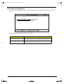
Basic System Configuration
The Basic System Configuration screen contains parameters involving basic computer settings like date and
time.
The table below describes the parameters in the screen.
Parameter
Date
Description
Sets the system date.
Format: DDD MMM DD YYYY (day-of-the-week month day year)
Time
Sets the system time.
Format: HH:MM:SS (hour:minute:second)
30
Chapter 1
505-1.book Page 31 Thursday, November 4, 1999 4:36 PM
Startup Configuration
The Startup Configuration screen contains parameters that are related to computer startup.
The table below describes the parameters in this screen. Settings in boldface are the default and suggested
parameter settings.
Parameter
Boot Display
Description
Sets the display on boot-up.
When set to Auto, the computer automatically determines the display device. If an
external display device (e.g., monitor) is connected, it becomes the boot display;
otherwise, the computer LCD is the boot display. When set to Both, the computer
outputs to both the computer LCD and an external display device if one is
connected.
Options: Auto or Both
Screen Expansion
When set to enabled, the screen will automatically adjust the display to fit the
screen when the resolution is set 640 X 480.
Options: Enabled or Disabled
Hotkey Beep
When enabled, the computer gives off a beep when a hotkey (key combination) is
pressed. See “Hot Keys” on page 5 for details on hotkeys.
Options: Enabled or Disabled
Fast Boot
Allows you to define your system’s booting process, whether to skip some POST
routines or proceed with the normal booting process.
Options: Enabled or Disabled
Boot Drive Sequence
Allows you to set the sequence wherein the computer will boot 1st, 2nd, and so on.
Below are possible boot devices.
Boot from CD-ROM
Enables boot-up from the CD-ROM drive, if selected as the first option. The
computer attempts to boot from the CD-ROM drive (looks for a bootable CD-ROM)
before following the boot sequence specified in the Boot Drive Sequence.
Floppy
Enables boot-up from the floppy disk drive, if selected as the first option. The
computer attempts to boot from the floppy disk drive (look for a bootable floppy)
before following the boot sequence specified in the Boot Drive Sequence.
Hard Disk
Enables boot-up from the hard disk drive.
Chapter 1
31
505-1.book Page 32 Thursday, November 4, 1999 4:36 PM
Onboard Device Configuration
The Onboard Device Configuration screen contains parameter settings for your hardware connection devices.
CAUTION: The parameters in this screen are for advanced users only. You do not need to change the values
in this screen because these values are already optimized.
The table below describes the parameters in this screen. Settings in boldface are the default and suggested
parameter settings.
Parameter
Serial Port
Description
Enables or disables the serial port.
Options: Enabled or Disabled
Base Address
Sets the I/O address of the serial port.
Options: 3F8h, 2F8h, 3E8h or 2E8h
IRQ
Sets the interrupt request of the serial port.
Parallel Port
Enables or disables the parallel port.
Options: 4 or 11
Options: Enabled or Disabled
Base Address
Sets the I/O address of the parallel port.
Options: 378h, 278h or 3BCh
IRQ
Sets the interrupt request of the parallel port.
Options: 7 or 5
Operation Mode
Sets the operation mode of the parallel port.
ECP DMA Channel
Sets a DMA channel for the printer to operate in ECP mode. This parameter
is enabled only if Operation Mode is set to ECP.
Options: ECP, EPP, Bidirectional or Standard
Options: 1 or 3
32
Chapter 1
505-1.book Page 33 Thursday, November 4, 1999 4:36 PM
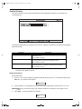
System Security
The System Security screen contains parameters that help safeguard and protect your computer from
unauthorized use.
The table below describes the parameters in this screen. Settings in boldface are the default and suggested
parameter settings.
Parameter
Setup Password
Description
When set, this password protects the BIOS Setup Utility from
unauthorized entry.
Options: None or Present
Power-on Password
When set, this password protects the computer from unauthorized
entry during boot-up or resume from Hibernation mode.
Hard Disk Password
When set, this password prevents the internal hard disk from
unauthorized access. It consists of 8 alphanumeric characters.
Options: None or Present
Options: None or Present
NOTE: Don’t forget your password, if you forget your password, you may have to return your notebook
computer to your dealer to reset it.
Setting a password
Follow these steps:
1.
Use the ↑ and ↓ keys to highlight a password parameter (Setup, Power-on, or Hard Disk) and press the
Enter key. The password box appears:
2.
Type a password. The password may consist of up to eight alphanumeric characters (A-Z, a-z, 0-9).
IMPORTANT:Be very careful when typing your password because the characters do not appear on the
screen.
3.
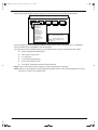
Press Enter. The retype password box appears.
Chapter 1
33
505-1.book Page 34 Thursday, November 4, 1999 4:36 PM
4.
Retype the password to verify your first entry and press Enter.
After setting the password, the computer automatically sets the chosen password parameter to Present.
5.
Press Esc to return to the main menu.
6.
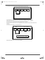
Press Esc. The following dialog box appears.
7.
Select Yes and press Enter to save the password and exit the BIOS Setup Utility.
Changing a password
To change a password, follow the same steps used to set a password.
Removing a password
To remove a password, use the ↑ and ↓ keys to highlight a password parameter and press the “Enter” key as
the first character.
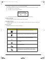
Password icons
Below are the password icons and their descriptions:
Parameters
34
Description
Power-on Password icon
When set to present, prompts the user to input the correct password for
the system to continue. It is shown after the TravelMate logo.
Hard Disk Password icon
When set to present, prompts the user to input the correct password for
the hard disk to operate. It is shown after the Power-on Password Icon.
Password character icon
When typing the characters of the password, the screen displays this icon
for each character instead of the actual password character.
Wrong password icon
If the wrong password is entered, this icon will be displayed beside the
wrong password.
Successful password entry icon
If the password is correctly entered, this icon will be displayed beside the
correctly entered password.
Password failure icon
The system allows the user 3 chances to type the correct password. After
the password has been incorrectly entered 3 times, this icon will be
displayed together with a short message stating “system shut-down”. The
user then has to reboot the system to try to type the correct password
again.
Chapter 1
505-1.book Page 35 Thursday, November 4, 1999 4:36 PM
Load Default Settings
When you select this menu item, the following dialog box displays:
To load factory-default settings for all the parameters, select Yes and press Enter. Otherwise, select No and
press Enter.
Chapter 1
35
505-1.book Page 36 Thursday, November 4, 1999 4:36 PM
AFlash Utility
The BIOS flash memory update is required for the following conditions:
New versions of system programs
New features or options
Use the AFlash utility to update the system BIOS flash ROM.
NOTE: Do not install memory-related drivers (XMS, EMS, DPMI) when you use AFlash.
NOTE: This program contains a readme.txt file. This readme.txt file will introduce how to use AFlash utility.
Executing AFlash
IMPORTANT:If this diskette is not bootable, do the following actions before you use it:
1.
Create a bootable disk.
2.
Copy all AFlash files into this bootable diskette.
3.
Put the bootable disk into TravelMate 505 series mobile, then re-boot.
IMPORTANT:Never turn off the system power while Flash BIOS is programming. This will damage your
system.
4.
After Flash BIOS is done, reboot the system.
NOTE: If any problems occured during BIOS updated, refer to “Index of PQA Diagnostic Error Code, Message”
on page 70 for troubleshooting.
36
Chapter 1
505-1.book Page 37 Thursday, November 4, 1999 4:36 PM
System Utility Diskette
This utility diskette is for the Acer TravelMate 505 notebook machine. It provides the following functions:
1.
Panel ID Utility
2.
Thermal and Fan Utility
3.
Mother Board Data Utility
To use this diskette, first boot from this diskette, then a “Microsoft Windows 98 Startup Menu” prompt you to
choose the testing item. Follow the instructions on screen to proceed.
NOTE: This program contains a readme.txt file. This readme.txt file will introduce each test utility and its
functions.
IMPORTANT: If t his diskette is not bootable, do the following actions before you use it:
1.
Do system transfers.
2.
Copy HIMEM.SYS to A:\.
3.
Copy EMM386.EXE to A:\
Panel ID Utility
There is an EEPROM in the inverter which stores its supported LCD type ID code. If you replace an LCD with
one of a different brand or use a new inverter, the ID information in the inverter EEPROM should be updated.
Follow the steps below to see the LCD Panel ID:
1. Follow the instructions on-screen to read current or to set new LCD Panel ID code.
NOTE: When you set a new LCD Panel ID and the new LCD is not yet enabled (to function), connect an
external CRT to see the program execution process.
NOTE: Make sure the new ID code you choose corresponds with the LCD brand and type. If you write a wrong
ID into the inverter, just reboot and re-execute the program and input the correct ID code.
2. Restart the computer - the new LCD should work normally.
NOTE: If LCD cannot display after changing the ID code, make sure you select the correct ID code, or try
reconnecting the LCD FPC cable connectors.
Thermal and Fan Utility
The system is equipped with sensors to protect against system overheating. By setting system and processor
thermal thresholds, the system can turn on the cooling fan or shut down automatically when temperatures
reach the defined threshold parameters. This utility will test fan, processor thermal and system thermal.
Mainboard Data Utility
This utility will display Mainboard Data (MBD) which includes header informaiton, product name, manufacture
name, UUID (Universally Unique IDentifiers) and serial number. This function can display and create MBD
data as well as store those information to LCD inverter EEPROM (not flash ROM). Following are specification
for this function.
1.
Read mother board data can display the MBD data.
2.
Create MBD header information, product name and manufacture name can create 3 informations and
write them to EEPROM automatically.
3.
Write MBD UUID can create and write a new UUID. This function is used when the original UUID is lost or
damaged. Use “Read Mother Board Data” first to keep the UUID.
4.
Write MBD serial number can keyin MBD serial number by user.
Chapter 1
37
505-1.book Page 38 Thursday, November 4, 1999 4:36 PM
System Diagnostic Diskette
IMPORTANT:The diagnostics program here that we used is called PQA (Product Quality Assurance) and is
provided by Acer Headquarters. You can utilize it as a basic diagnostic tool. To get this program,
either download it from http://csd.acer.com.tw or find it in the TravelMate 505 service CD kit.
To better fit local service requirements, your regional office MAY have other diagnostic program.
Please contact your regional offices or the responsible personnel/channel to provide you with further
technical details.
NOTE: This program contains a readme.txt file. This readme.txt file will introduce each test and its functions.
This diagnostic program divided into two diskettes is for the Acer TravelMate 505 notebook machine. It
provides the following functions:
1.
PQA System Diagnostics
2.
Audio Resource and Speaker Out Test
3. USB Register and Connect / Disconnect Test
NOTE: A USB device is required when executing the USB Connection / Disconnection Test, or this test fails.
4.
Exit
To use this diskette, first boot from this diskette, then a “Microsoft Windows 98 Startup Menu” prompts you to
choose the testing item. Follow the instructions on screen to proceed.
IMPORTANT: This diskette is not bootable, do the following actions before you use it:
1.
Do system transfers.
2.
Copy the following files to A:\
HIMEM.SYS
RAMDRIVE.SYS
LASTDRV.COM
MSCDEX.EXE
NOTE: When executing a parallel or serial port test in System Test item, a loopback tool is needed. This
loopback is Acer proprietary design. You may reach the [email protected] for ordering
information.
Running PQA Diagnostics Program.
PQA
Diag
Vx_x
Result
SysInfo
Option
xx-xx-xx
Exit
Press → ← to move around the main menu. Press Enter to enable the selected option. The main options are
Diag, Result, SysInfo, Option and Exit.
The Diag option lets you select testing items and times.
38
Chapter 1
505-1.book Page 39 Thursday, November 4, 1999 4:36 PM
The following screen appears when you select Diag from the main menu.
PQ A
Vx_ x
R esult
D iag
SysInfo
xx-xx-xx
Option
Exit
Diag
O NE
M ULT I
FU LL
Q UIC K
TE S T
TE S T
TE S T
TE S T
One Test Performs a single test and manual checks the selected test items in sequence.
Multi Test Performs multiple tests and manual checks the selected test items in sequence.
Full Test Performs all items and full check the all test items in sequence.
Quick Test Performs special tests of the highlighted items and quickly check the selected test items in
sequence.
The screen below appears if you select Multi Test.
P
PQ
QA
A
D
D ia
ia gg
V
V x_
x_ xx
R
R esu
esu ltlt
D
ia
g
D ia g
O NE
O UneLTI
M
M u lti
FU LL
Q U IC K
S
S ysInfo
ysInfo
xx x-x
x-x x-x
x-x xx
O
O ption
ption
E x it
E x it
TE S T
T ESST T
TE
TE S T
TEST
TE S T
TE S T C O U N T VA L U E (1...9 999 ) 1
Specify the desired number of tests and press Enter.
Chapter 1
39
505-1.book Page 40 Thursday, November 4, 1999 4:36 PM
After you specify the number of tests to perform, the screen shows a list of test items (see below):
PQ A
Result
D iag
Diag
M AN U ALTest
TESItem
T s
AU TO[ ] System
T EST B oard
[ ] M em ory
[ ] Keyboard
[ ] Video
[ ] Parallel P ort
[ ] Serial Port
[ ] Diskette D rive
[ ] Hard D isk
[ ] CD -RO M
[ ] Coprocessor
[ ] Pointing D ev.
[ ] Cache
V x_x
SysInfo
O ption
xx-xx-xx
E xit
SPA C E: m ark/unm ark selecting item
ES C : return to upper m enu
F2
: test the m arked item (s)
EN T ER : open subitem ’s m enu
Test Tim es = 1
Move the highlight bar from one item to another. Press a space to mark or unmark the item. Press Enter to
open the subitem menu. Press Esc to close the submenu.
The right corner screen information gives you the available function keys and the specified test number.
Space: mark/unmark selecting item
ESC: return to upper menu
F1: help menu
F2: tests the marked item(s)
Enter: Open subitem’s menu
Test Times: Indicates the number of tests to perform
NOTE: The F1 and F2 keys function only after you finish configuring the Test option.
NOTE: If there are any problems occured during BIOS updated, refer to “Index of PQA Diagnostic Error Code,
Message” on page 70 for troubleshooting.
40
Chapter 1
505-1.book Page 41 Thursday, November 4, 1999 4:36 PM
Chapter 3
Machine Disassembly and Replacement
This chapter contains step-by-step procedures on how to disassemble the notebook computer for
maintenance and troubleshooting.
To disassemble the computer, you need the following tools:
Wrist grounding strap and conductive mat for preventing electrostatic discharge
Flat-bladed screwdriver
Phillips screwdriver
Tweezers
Flat-bladed screwdriver or plastic stick
NOTE: The screws for the different components vary in size. During the disassembly process, group the
screws with the corresponding components to avoid mismatch when putting back the components.
Chapter 3
41
505-1.book Page 42 Thursday, November 4, 1999 4:36 PM
General Information
Before You Begin
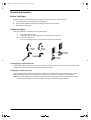
Before proceeding with the disassembly procedure, make sure that you do the following:
1.
Turn off the power to the system and all peripherals.
2.
Unplug the AC adapter and all power and signal cables from the system.
3.
Remove the battery pack.
Connector Types
There are two kinds of connectors on the system board:
Connectors with no locks
Unplug the cable by simply pulling out the cable from the connector.
Connectors with locks
You can use a plastic stick to lock and unlock connectors with locks.
Unplugging
the Cable
Plugging
the Cable
Unplugging
the Cable
Plugging
the Cable
Unplugging the cable with locks
To unplug the cable, first unlock the connector by pulling up the two clasps on both sides of the connector with
a plastic stick. Then carefully pull out the cable from the connector.
Plugging the cable with locks
To plug the cable back, first make sure that the connector is unlocked, then plug the cable into the connector.
With a plastic stick, press the two clasps on both sides of the connector to secure the cables in place.
NOTE: The cables used here are special FPC (flexible printed-circuit) cables and more delicate than normal
plastic-enclosed cables. Do not force cables out of the connectors to prevent damage.
42
Chapter 3
505-1.book Page 43 Thursday, November 4, 1999 4:36 PM
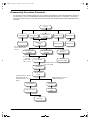
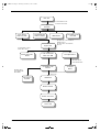
Disassembly Procedure Flowchart
The flowchart on the succeeding page gives you a graphic representation on the entire disassembly sequence
and instructs you on the components that need to be removed during servicing. For example, if you want to
remove the system board, you must first remove the keyboard, then disassemble the inside assembly frame in
that order.
START
DIMM Door
Middle Cover
(short)
Hinge caps
Middle Cover
(Long)
DIMM Module
86.1A522.140 *2
Screw MACH PAN
M2*14L
LCD FPC Cable
from M/B
Modem Cover
Battery Pack
Modem Board
Battery Door
LED Board Cable
from M/B
86.1A353.135
*2 Screw
MACH PAN
M2.5 *13.5L
Keyboard
Main Unit
(see next page)
LCD Module
86.9A523.6R0 *5 Screw
M2.5*6L B/ZN
LCD Bezel
LCD & Inverter
board
86.9A522.4R0 *2 Screw
MACH PAN M2*4L
86.5A524.4R0 *4 Screw
M3*4L
86.9A522.4R0 *2 Screw
MACH PAN M2*4L
Inverter Board
LED Board
LCD FPC Cable
LED Board
Cable
LCD Panel
Chapter 3
43
505-1.book Page 44 Thursday, November 4, 1999 4:36 PM
Main Unit
86.1A523.6R0*2 Screw
86.1A522.140*3 Screw
Heatsink
Cover Switch
Cable from M/B
Touchpad Board
Cable from M/B
RTC Battery Cable
from M/B
HDD Module
Upper case
86.1A353.135 *10 Screw MACH
PAN M2.5*13.5L
86.1A523.6R0 *1 Screw MACH
M2.5*6L
86.1A523.6R0 *2 Screw
MACH M2.5 *6L NI
Battery and Audio
Board
FDD & CD-ROM
Cable from M/B
Touchpad Module
86.9A522.3R0 *6
Screw MACH M2*3L
CD-ROM & FDD
Module
86.9A522.4R0 *4
Screw MACH PAN
M2*4L B/ZN
L/R Channel
Speaker
Touchpad
Board
86.1A523.6R0 *2 Screw MACH
M2.5*6L NI
Mainboard
Modem Bracket
Modem Connector
Lower case
44
Chapter 3
505-1.book Page 45 Thursday, November 4, 1999 4:36 PM
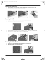
Removing the Battery Pack
1.
Press the battery cover release latch down and slide the battery pack out from the main unit.
2.
Remove the battery cover from the battery pack carefully.
Removing the DIMM
1.
To remove the DIMM module, remove the two screws from the DIMM cover.
2.
Then, remove the DIMM cover from the lower case.
3.
Use two flat-bladed screwdrivers to push the latches outward on both sides of the DIMM socket.
4.
Then, remove the extended DIMM module from the DIMM socket.
Removing the Modem Board
1.
To remove the modem board, first remove the screw from the modem cover.
2.
Remove the modem cover from the lower case.
Chapter 3
45
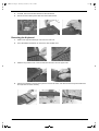
505-1.book Page 46 Thursday, November 4, 1999 4:36 PM
3.
At CN20, remove the modem board from the mainboard.
4.
Disconnect the modem power cable from the modem board.
Removing the Keyboard
46
1.
Slide out the right and left hinge cover from the main unit.
2.
Use a flat-bladed screwdriver to remove the short middle cover.
3.
Slide the long middle cover to the left side then remove it from the upper case.
4.
Pull out and upward to expose the keyboard connector at CN19, and disconnect the keyboard cable from
the keyboard connector carefully.
Chapter 3
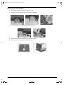
505-1.book Page 47 Thursday, November 4, 1999 4:36 PM
Removing the LCD Module
1.
Remove the two screws holding the LCD FPC cable
2.
At CN9, disconnect the LCD FPC cable from the mainboard.
3.
At CN7, disconnect the LED cable from the mainboard.
4.
Remove the two screws holding the LCD module as shown.
5.
Next, remove the LCD module from the main unit.
Chapter 3
47
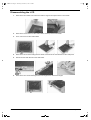
505-1.book Page 48 Thursday, November 4, 1999 4:36 PM
Disassembling the LCD
48
1.
Remove the two rubber LCD cushions and the 3 hinge screw caps from the LCD module.
2.
Remove the five screws from the LCD module, and snap out the LCD bezel.
3.
Then, remove it from the LCD module.
4.
Remove the two screws holding the LED board, and remove the LED board from the LCD panel.
5.
Disconnect the LED cable from the LED board.
6.
Remove the four screws holding the two LCD hinges, then remove the hinges.
Chapter 3
505-1.book Page 49 Thursday, November 4, 1999 4:36 PM
7.
Remove the two screws holding the inverter. Now, lift off the inverter gently.
8.
Disconnect the LCD power cable and LCD FPC cable from the inverter board.
9.
Remove the four screws holding the LCD, then gently remove the LCD from the LCD panel.
10. Tear off the adhesive tape.
11. Disconnect the LCD FPC cable from the LCD.
Chapter 3
49
505-1.book Page 50 Thursday, November 4, 1999 4:36 PM
Disassembling the Main Unit
Removing the Heatsink and CPU EMI Shield
1.
Remove the five screws holding the system heatsink.
2.
Slide the heatsink to the left side and take it out from the main unit.
3.
Remove the CPU EMI shield from the main unit.
4.
At CN8, disconnect the RTC battery cable from the mainboard and then lift it away from the upper case.
Removing the Hard Disk Drive
50
1.
At CN17, remove the hard disk drive from the mainboard.
2.
At CN18, disconnect the touchpad cable from the mainboard.
Chapter 3
505-1.book Page 51 Thursday, November 4, 1999 4:36 PM
Removing Upper Case
1.
To release the upper case, first remove the eleven screws from the main unit.
2.
Lift the upper case gently.
3.
At CN6, disconnect the cover switch cable from the mainboard, then remove the upper case.
Removing the Floppy Disk Drive/CD-ROM Drive Combo Module
1.
Disconnect the CD-ROM drive cable and floppy disk drive cable at CN16 and CN 15 respectively.
Chapter 3
51
505-1.book Page 52 Thursday, November 4, 1999 4:36 PM
2.
Remove the screw shown here.
3.
Remove the CD-ROM drive screw cap from the bottom of the main unit.
4.
Remove the screw shown here.
5.
Now, remove the floppy disk drive and CD-ROM drive combo module from the main unit.
Removing the Speakers
52
1.
Disconnect the left and right speaker cables from the audio I/O and battery connection board at CN1 and
CN2 respectively.
2.
Remove the four screws holding the two speakers, then remove the two speakers from the lower case.
Chapter 3
505-1.book Page 53 Thursday, November 4, 1999 4:36 PM
Removing the Audio I/O and Battery Connection Board
1.
Remove the two screws holding the audio I/O and battery connection board, then remove it from the
mainboard.
Removing the Fan
1.
Disconnect the fan cable from the mainboard.
2.
Remove the two screws holding the fan, then lift the fan from the lower case.
Removing the Mainboard
1.
Remove the two screws holding the mainboard, then remove the mainboard from the lower case.
2.
Remove the modem phone jack connector from the lower case.
Chapter 3
53
505-1.book Page 54 Thursday, November 4, 1999 4:36 PM
Removing the PCMCIA Card
1.
Remove the four screws holding the PCMCIA slot.
2.
At CN13, disconnect the PCMCIA slot from the mainboard.
Removing the Touchpad Module
54
1.
To remove the touchpad module, first release the touchpad cable from the position shown here.
2.
Remove the six screws holding the touchpad bracket.
3.
Now, lift the touchpad module away from the upper case.
4.
Disconnect the touchpad cable from the touchpad board, then remove the touchpad bracket.
Chapter 3
505-1.book Page 55 Thursday, November 4, 1999 4:36 PM
Disassembling the Hard Disk Drive Module
1.
To disassemble the hard disk drive module, first remove the six screws as shown here.
2.
Detach the left and right brackets from the hard disk drive.
3.
Remove the hard disk drive connection board from the hard disk drive.
Chapter 3
55
505-1.book Page 56 Thursday, November 4, 1999 4:36 PM
Disassembling the Floppy Disk Drive and CD-ROM Combo Module
56
1.
To disassemble the CD-ROM drive from the combo module, first remove the three screws as shown here..
2.
Disconnect the CD-ROM FPC cable, then slide out the CD-ROM drive from the chassis.
3.
Remove the CD-ROM FPC cable from the chassis.
4.
To remove the floppy disk drive from the combo module, first remove the three screws as shown here.
5.
Remove the floppy disk drive from the chassis.
6.
Disconnect the floppy disk drive FPC cable from the floppy disk drive.
Chapter 3
505-1.book Page 57 Thursday, November 4, 1999 4:36 PM
Chapter 4
Troubleshooting
Use the following procedure as a guide for computer problems.
NOTE: The diagnostic tests are intended to test only Acer products. Non-Acer products, prototype cards, or
modified options can give false errors and invalid system responses.
1.
Obtain the failing symptoms in as much detail as possible.
2.
Verify the symptoms by attempting to re-create the failure by running the diagnostic test or by repeating
the same operation.
3.
Use the following table with the verified symptom to determine which page to go to.
Symptoms (Verified)
Go To
Power failure. (The power indicator does not go on or
stay on.)
Power System check
POST does not complete. No beep or error codes are
indicated.
Symptom-to-FRU Index
POST detects an error and displayed messages on
screen.
Error Messages List
The diagnostic test detected an error and displayed a
FRU code.
Running PQA Diagnostic Program
Undetermined Problems
Other symptoms (i.e. LCD display problems or others). Error Symptom-to-FRU Index
Symptoms cannot be re-created (intermittent
problems).
Use the customer-reported symptoms and go to Error
Symptom-to-FRU Index.
Intermittent Problems
Undetermined Problems
Chapter 4
57
505-1.book Page 58 Thursday, November 4, 1999 4:36 PM
System Check Procedures
Diskette Drive Check
Do the following to isolate the problem to a controller, driver, cable or diskette. A write-enabled, diagnostic
diskette is required.
NOTE: Make sure that the diskette does not have more than one label attached to it. Multiple labels can cause
damage to the drive or cause the drive to fail.
Do the following to select the test device.
1.
Boot from the diagnostics diskette and start the PQA program.
2.
Go to the diagnostic Diskette Drive in the test items.
3.
Press F2 in the test items.
4.
Follow the instructions in the message window.
If an error occurs with the internal diskette drive, reconnect the diskette connector on the system board.
If the error still remains:
1.
Reconnect the diskette drive.
2.
Replace the diskette driver cable.
3.
Replace the diskette drive.
4.
Replace the system board.
CD-ROM Drive Check
Do the following to isolate the problem to a controller, drive, cable, or CD-ROM. Make sure that the CD-ROM
does not have any label attached to it. The label can cause damage to the drive or can cause the drive to fail.
Do the following to select the test device:
1.
Boot from the diagnostics diskette and start the PQA program.
2.
Go to the diagnostic CD-ROM in the test items.
3.
Press F2 in the test items.
4.
Follow the instructions in the message window.
If an error occurs, reconnect the connector on the System board. If the error still remains:
1.
Reconnect the CD-ROM drive.
2.
Replace the diskette driver cable.
3.
Replace the CD-ROM drive.
4.
Replace the system board.
Keyboard or Auxiliary Input Device Check
Remove the external keyboard if the internal keyboard is to be tested.
If the internal keyboard does not work or an unexpected character appears, make sure that the flexible cable
extending from the keyboard is correctly seated in the connector on the system board.
If the keyboard cable connection is correct, run the Keyboard Test. See “Running the Diagnostics” for details.
If the tests detect a keyboard problem, do the following one at a time to correct the problem. (Do not replace a
non-defective FRU):
58
1.
Reconnect the keyboard cables.
2.
Replace the keyboard.
3.
Replace the system board.
Chapter 4
505-1.book Page 59 Thursday, November 4, 1999 4:36 PM
The following auxiliary input devices are supported by this computer:
Numeric keypad
External keyboard
If any of these devices do not work, reconnect the cable connector and repeat the failing operation.
Memory Check
Memory errors might stop system operations, show error messages on the screen, or hang the system.
1.
Boot from the diagnostics diskette and start the PQA program (please refer to “Running PQA Diagnostics
Program”).
2.
Go to the diagnostic memory in the test items.
3.
Press F2 in the test items.
4. Follow the instructions in the message window.
NOTE: Make sure that the DIMM is fully installed into the connector. A loose connection can cause an error.
Power System Check
To verify the symptom of the problem, power on the computer using each of the following power sources:
1.
Remove the battery pack.
2.
Connect the power adapter and check that power is supplied.
3.
Disconnect the power adapter and install the charged battery pack; then check that power is supplied by
the battery pack.
If you suspect a power problem, see the appropriate power supply check in the following list:
“Check the Power Adapter”
“Check the Battery Pack”
Check the Power Adapter
Unplug the power adapter cable from the computer and measure the output voltage at the plug of the power
adapter cable. See the following figure
Pin 1: +19 to +20.5V
Pin 2: 0V, Ground
1.
If the voltage is not correct, replace the power adapter.
2.
If the voltage is within the range, do the following:
Replace the System board.
If the problem is not corrected, see “Undetermined Problems”.
If the voltage is not correct, go to the next step.
NOTE: An audible noise from the power adapter does not always indicate a defect.
3.
If the power problem occurs only when the port replicator is used, replace the port replicator.
4.
If the power-on indicator does not light up, check the power cord of the power adapter for correct
continuity and installation.
5.
If the operational charge does not work, see “Check the Battery Pack”.
Chapter 4
59
505-1.book Page 60 Thursday, November 4, 1999 4:36 PM
Check the Battery Pack
To check the battery pack, do the following:
1.
Power off the computer.
2.
Remove the battery pack and measure the voltage between battery terminals 2(+) and 7(ground). See the
following figure
3.
If the voltage is still less than 8.0 Vdc after recharging, replace the battery.
To check the battery charge operation, use a discharged battery pack or a battery pack that has less than 50%
of the total power remaining when installed in the computer.
If the battery status indicator does not light up, remove the battery pack and let it return to room temperature.
Re-install the battery pack.
If the charge indicator still does not light up, replace the battery pack. If the charge indicator still does not light
up, replace the system board.
Touchpad Check
If the touchpad doesn’t work, do the following actions one at a time to correct the problem. Do not replace a
non-defective FRU:
1.
Reconnect the touchpad cables.
2.
Replace the touchpad.
3.
Replace the system board.
After you use the touchpad, the pointer drifts on the screen for a short time. This self-acting pointer movement
can occur when a slight, steady pressure is applied to the touchpad pointer. This symptom is not a hardware
problem. No service actions are necessary if the pointer movement stops in a short period of time.
60
Chapter 4
505-1.book Page 61 Thursday, November 4, 1999 4:36 PM
Index of Error Message
The symptom-to-FRU index lists the symptoms and errors and their possible causes. The most likely cause is
listed first.
NOTE: Perform the FRU replacement or actions in the sequence shown in FRU/Action column, if the FRU
replacement does not solve the problem, put the original part back in the computer. Do not replace a
non-defective FRU.
This index can also help you determine the next possible FRU to be replaced when servicing a computer.
If the symptom is not listed, see “Undetermined Problems” on page 69.
The following lists the error messages that the BIOS displays on the screen and the error symptoms classified
by function.
NOTE: Most of the error messages occur during POST. Some of them display information about a hardware
device, e.g., the amount of memory installed. Others may indicate a problem with a device, such as the
way it has been configured.
NOTE: If the system fails after you make changes in the BIOS Setup Utility menus, reset the computer, enter
Setup and install Setup defaults or correct the error
Error Messages List
Error Messages
Failure Fixed Disk
Action in Sequence
Reconnect hard disk drive connector.
“Load Default Settings” in BIOS Setup Utility.
Hard disk drive
System board
Stuck Key
“Keyboard or Auxiliary Input Device Check” .
Keyboard error
“Keyboard or Auxiliary Input Device Check”.
Keyboard Controller Failed
“Keyboard or Auxiliary Input Device Check”.
Keyboard locked - Unlock key switch
Unlock external keyboard.
Monitor type does not match CMOS - Run Setup
Run “Load Default Settings” in BIOS Setup Utility.
Shadow RAM Failed at offset: nnnn
BIOS ROM
System board
System RAM Failed at offset: nnnn
DIMM
System board
Extended RAM Failed at offset: nnnn
DIMM
System board
System battery is dead - Replace and run Setup
Replace RTC battery and Run BIOS Setup Utility to
reconfigure system time, then reboot system.
System CMOS checksum bad - Default configuration
used
RTC battery
System timer error
RTC battery
Run BIOS Setup Utility to reconfigure system time,
then reboot system.
Run BIOS Setup Utility to reconfigure system time,
then reboot system.
System board
Real time clock error
RTC battery
Run BIOS Setup Utility to reconfigure system time,
then reboot system.
System board
Previous boot incomplete - Default configuration used
Run “Load Default Settings” in BIOS Setup Utility.
RTC battery
System board
Chapter 4
61
505-1.book Page 62 Thursday, November 4, 1999 4:36 PM
Error Messages List
Error Messages
Memory size found by POST differed from CMOS
Action in Sequence
Run “Load Default Settings” in BIOS Setup Utility.
DIMM
System board
Diskette drive A error
Check that the drive is defined with the proper diskette
type in BIOS Setup Utility.
Diskette Drive Check.
Incorrect Drive A type - run SETUP
Check that the drive is defined with the proper diskette
type in BIOS Setup Utility
Diskette Drive Check.
System cache error - Cache disabled
CPU board
System board
CPU ID
CPU board
System board
DMA Test Failed
DIMM
CPU board
System board
Software NMI Failed
DIMM
CPU board
System board
Fail-Safe Timer NMI Failed
DIMM
CPU board
System board
Device Address Conflict
Run “Load Default Settings” in BIOS Setup Utility.
RTC battery
System board
Allocation Error for device
Run “Load Default Settings” in BIOS Setup Utility.
RTC battery
System board
Failing Bits: nnnn
DIMM
BIOS ROM
System board
Fixed Disk n
Invalid System Configuration Data
None
BIOS ROM
System board
I/O device IRQ conflict
Run “Load Default Settings” in BIOS Setup Utility.
RTC battery
System board
Operating system not found
Enter Setup and see if fixed disk and drive A are
properly identified.
Diskette drive
Hard disk drive
System board
62
Chapter 4
505-1.book Page 63 Thursday, November 4, 1999 4:36 PM
No-Beep Symptoms
Symptom / Error
No beep, power-on indicator turns off and LCD is
blank.
Action in Sequence
Power source (battery pack and power adapter).
Power System Check.
Ensure every connector is connected tightly and
correctly.
Reconnect the DIMM.
CPU board
DC-DC/charger board
System board.
No beep, power-on indicator turns on and LCD is
blank.
Power source (battery pack and power adapter).
Power System Check.
Reconnect the LCD connectors
Hard disk drive
LCD inverter ID
LCD FPC cable
Inverter
LCD
System board
No beep, power-on indicator turns on and LCD is
blank. But you can see POST on an external CRT.
Reconnect the LCD connectors.
LCD inverter ID
LCD FPC cable
LCD inverter
LCD
System board
No beep, power-on indicator turns on and a blinking
cursor shown on LCD during POST.
Ensure every connector is connected tightly and
correctly.
System board
No beep during POST but system runs correctly.
Speaker
Audio/Battery connection board
System board
Chapter 4
63
505-1.book Page 64 Thursday, November 4, 1999 4:36 PM
Index of Symptom-to-FRU Error Message
LCD-Related Symptoms
Symptom / Error
LCD backlight doesn't work
Action in Sequence
LCD is too dark
Enter BIOS Utility to execute “Load Setup Default
Settings”, then reboot system.
LCD brightness cannot be adjusted
Reconnect the LCD connectors.
LCD contrast cannot be adjusted
Keyboard (if contrast and brightness function key
doesn't work).
LCD inverter ID
LCD FPC cable
LCD inverter
LCD
System board
Unreadable LCD screen
Reconnect the LCD connectors.
Missing pels in characters
LCD inverter ID
Abnormal screen
LCD FPC cable
Wrong color displayed
LCD inverter
LCD
System board
LCD has extra horizontal or vertical lines displayed.
LCD inverter ID
LCD inverter
LCD FPC cable
LCD
System board
Indicator-Related Symptoms
Symptom / Error
Indicator incorrectly remains off or on, but system runs
correctly.
Action in Sequence
Reconnect the LED board
LED board
System board
Power-Related Symptoms
Symptom / Error
Power shuts down during operation.
Action in Sequence
Power source (battery pack and power adapter).
Power System Check.
Battery pack
Power adapter
Audio-I/O & battery connection board
System board
The system doesn’t power-on.
Power source (battery pack and power adapter).
Power System Check.
Battery pack
Power adapter
Audio-I/O & battery connection board
System board
The system doesn’t power-off.
Power source (battery pack and power adapter).
Power System Check.
Hold and press the power switch for more than 4
seconds.
System board
64
Chapter 4
505-1.book Page 65 Thursday, November 4, 1999 4:36 PM
Power-Related Symptoms
Symptom / Error
Battery can’t be charged
Action in Sequence
Power System Check
Battery pack
System board
PCMCIA-Related Symptoms
Symptom / Error
System cannot detect the PC Card (PCMCIA)
Action in Sequence
PCMCIA slot assembly
System board
PCMCIA slot pin is damaged.
PCMCIA slot assembly
Memory-Related Symptoms
Symptom / Error
Action in Sequence
Memory count (size) appears different from actual size. Enter BIOS Setup Utility to execute “Load Default
Settings, then reboot system.
DIMM
System board
Speaker-Related Symptoms
Symptom / Error
In DOS or Windows, multimedia programs, no sound
comes from the computer.
Action in Sequence
Press Fn-F8, Speaker ON/OFF control.
Audio driver
Speaker
Audio/Battery connection board
System board
Internal speakers make noise or emit no sound.
Press Fn-F8, Speaker ON/OFF control.
Speaker
Audio/Battery connection board
System board
Power Management-Related Symptoms
Symptom / Error
The system will not enter hibernation
Action in Sequence
Keyboard (if control is from the keyboard)
Hard disk drive
System board
Check with Sleep Manager.
The system doesn't enter hibernation mode and four
short beeps every minute.
Hibernation Mode
Press Fn+F4 and see if the computer enters
hibernation mode.
Touchpad
Keyboard
Hard disk connection board
Hard disk drive
System board
The system doesn’t enter standby mode after closing
the LCD
Standby Mode
LCD cover switch
System board
The system doesn't resume from hibernation mode.
Hibernation Mode
Hard disk connection board
Hard disk drive
System board
Chapter 4
65
505-1.book Page 66 Thursday, November 4, 1999 4:36 PM
Power Management-Related Symptoms
Symptom / Error
The system doesn't resume from standby mode after
opening the LCD.
Action in Sequence
Standby Mode
LCD cover switch
System board
Battery fuel gauge in Windows doesn’t go higher than
90%.
Remove battery pack and let it cool for 2 hours.
Refresh battery (continue to use battery until power off,
then charge battery).
Battery pack
Charger board
System board
System hangs intermittently.
Set Thermal Sensor Threshold.
Reconnect hard disk/CD-ROM drives.
Hard disk connection board
System board
Peripheral-Related Symptoms
Symptom / Error
System configuration does not match the installed
devices.
Action in Sequence
Enter BIOS Setup Utility to execute “Load Default
Settings”, then reboot system.
Reconnect hard disk/CD-ROM/diskette drives.
External display does not work correctly.
Press Fn+F5, LCD/CRT/Both display switching
Running PQA Diagnostics Program.
System board
USB does not work correctly.
System Diagnostics Diskette
System board
Print problems.
Ensure that the “Parallel Port” in the “Onboard Devices
Configuration” of BIOS Setup Utility is set to Enabled.
Onboard Devices Configuration
Run printer self-test.
Printer driver
Printer cable
Printer
System Board
Serial or parallel port device problems.
Ensure that the “Serial Port” in the “Onboard Devices
Configuration” of BIOS Setup Utility is set to Enabled.
Device driver
Device cable
Device
System board
Keyboard/Touchpad-Related Symptoms
Symptom / Error
Keyboard (one or more keys) does not work.
Action in Sequence
Reconnect the keyboard cable.
Keyboard
System board
Touchpad does not work.
Reconnect touchpad cable.
Touchpad board
System board
66
Chapter 4
505-1.book Page 67 Thursday, November 4, 1999 4:36 PM
Modem-Related Symptoms
Symptom / Error
Internal modem does not work correctly.
Action in Sequence
System Diagnostics Diskette
Modem phone jack
Modem board
System board
NOTE: If you cannot find a symptom or an error in this list and the problem remains, see “Undetermined
Problems” on page 69.
Chapter 4
67
505-1.book Page 68 Thursday, November 4, 1999 4:36 PM
Intermittent Problems
Intermittent system hang problems can be caused by a variety of reasons that have nothing to do with a
hardware defect, such as: cosmic radiation, electrostatic discharge, or software errors. FRU replacement
should be considered only when a recurring problem exists.
When analyzing an intermittent problem, do the following:
68
1.
Run the advanced diagnostic test for the system board in loop mode at least 10 times.
2.
If no error is detected, do not replace any FRU.
3.
If any error is detected, replace the FRU. Rerun the test to verify that there are no more errors.
Chapter 4
505-1.book Page 69 Thursday, November 4, 1999 4:36 PM
Undetermined Problems
The diagnostic problems does not identify which adapter or device failed, which installed devices are incorrect,
whether a short circuit is suspected, or whether the system is inoperative.
Follow these procedures to isolate the failing FRU (do not isolate non-defective FRU).
NOTE: Verify that all attached devices are supported by the computer.
NOTE: Verify that the power supply being used at the time of the failure is operating correctly.
1.
Power-off the computer.
2.
Visually check them for damage. If any problems are found, replace the FRU.
3.
Remove or disconnect all of the following devices:
Non-Acer devices
Devices attached to the port replicator
Printer, mouse, and other external devices
Battery pack
Hard disk drive
DIMM
CD-ROM
Diskette drive
PC Cards
4.
Power-on the computer.
5.
Determine if the problem has changed.
6.
If the problem does not recur, reconnect the removed devices one at a time until you find the failing FRU.
7.
If the problem remains, replace the following FRU one at a time. Do not replace a non-defective FRU:
Chapter 4
System board
LCD assembly
69
505-1.book Page 70 Thursday, November 4, 1999 4:36 PM
Index of PQA Diagnostic Error Code, Message
Error Code
Message
16XXX
Backup battery error
01XXX
CPU or main board error
Action in Sequence
Backup battery
Reload BIOS default setting.
System board
02XXX
Memory error
03XXX
Keyboard error
DIMM
System board
Reset Keyboard
Keyboard
System board
04XXX
Video error
System board
05XXX
Parallel Port error
System board
06XXX
Serial port or main board error
System board
07XXX
Diskette drive error
Diskette drive
System board
08XXX
Hard disk error
Reload BIOS default setting
Hard disk
System board
09XXX
CD-ROM error
Reset CD-ROM cable
CD-ROM drive
System board
10XXX
Co-processor error
11XXX
Pointing device error
System board
Reset Keyboard
Keyboard
System board
12XXX
70
Cache test error
System board
Chapter 4
505-1.book Page 71 Thursday, November 4, 1999 4:36 PM
Chapter 5
Jumper and Connector Locations
Top View
CN2
CN7
CN3
CN4 CN1 CN5 JK1
CN6
CN11
CN9
CN12
CN10 CN8
CN13
SW2
CN14
CN16
CN15
CN17
CN19
CN18
PCB No. 99206
CN1
PS/2 Port
CN12
Golden Finger for Debug
CN2
VGA Port
CN13
PCMCIA Slot
CN3
Parallel Port
CN14
Fan Connector
CN4
Serial Port
CN15
Diskette Drive Connector
CN5
USB Port
CN16
CD-ROM Connector
CN6
LCD Cover Switch Connector
CN17
HDD Connector
CN7
LED Board Connector
CN18
Touch Pad Connector
CN8
RTC Battery Connector
CN19
Internal Keyboard Connector
CN9
LCD Connector
JK1
AC Adapter Connector
CN10
Fan Connector (Reserve)
SW2
Keyboard Type / OEM /Password Switch
CN11
Power Push Switch
SW2 Settings
Setting
Switch 1, Switch 2, Switch 6
Off, Off, Off : English Keyboard
On, Off, Off : Japanese Keyboard
Off, On, Off : European Keyboard
Off, Off, On : UK Keyboard
Switch 5
On : Bypass password
Off : Check password
Chapter 5
71
505-1.book Page 72 Thursday, November 4, 1999 4:36 PM
Bottom View
DM1
CN20
CN21
72
CN20
Modem Board Connector
CN21
Audio / Battery Connector
DM1
DIMM Socket
Chapter 5
505-1.book Page 73 Thursday, November 4, 1999 4:36 PM
Chapter 6
FRU (Field Replaceable Unit) List
This chapter gives you the FRU (Field Replaceable Unit) listing in global configurations of TravelMate 505P.
Refer to this chapter whenever ordering for parts to repair or for RMA (Return Merchandise Authorization).
IMPORTANT:Please note that WHEN ORDERING FRU PARTS, you should check the most up-to-date
information available on your regional web or channel. For whatever reasons a part number change
is made, it will not be noted in the printed Service Guide. For ACER-AUTHORIZED SERVICE
PROVIDERS, your Acer office may have a DIFFERENT part number code to those given in the FRU
list of this printed Service Guide. You MUST use the local FRU list provided by your regional Acer
office to order FRU parts for repair and service of customer machines.
NOTE: To scrap or to return the defective parts, you should follow the local government ordinance or
regulations on how best to dispose it, or follow the rules set by your regional Acer office on how to
return it.
NOTE: The number indicates the location shown on exploded diagram or “NS” indicates “Not shown” on it
Chapter 6
73
505-1.book Page 74 Thursday, November 4, 1999 4:36 PM
74
Chapter 6
505-1.book Page 75 Thursday, November 4, 1999 4:36 PM
Picture
No.
Partname
Description
Part No.
LCD
Chapter 6
33
LCD Module 12.1” DSTN
Sharp
ASSY LCD 12.1” DSTN
SHARP TM505
6M.43F01.001
NS
12.1” SVGA DSTN LCD,
Sharp
LCD 12.1” DSTN
LM121SS1T53 BLACK
56.0743B.001
NS
LCD Bezel
ASSY LCD BZL 12.1”
FALCON
60.43F01.001
NS
LCD Panel DSTN
ASSY PNL 12.1”
SHARP FALCON
60.43F07.001
NS
12.1” Inverter, Ambit
INVERTER
T62.121.C.00.510
19.21030.461
NS
LED Board
EXTENSA 700 LED
BOARD
55.47A03.001
NS
LCD FPC DSTN Cable
C.A FPC 12.1” DSTN
SHARP 510
50.45C07.001
75
505-1.book Page 76 Thursday, November 4, 1999 4:36 PM
Picture
76
No.
Partname
Description
Part No.
NS
LED Cable
W.A 10/10P 120MM
LED AN500
50.45B11.001
33
LCD Module 12.1” TFT
Hitachi
ASSY LCD 12.1” TFT
HITACHI TM505
6M.43F01.011
NS
12.1” SVGA TFT LCD,
Hitachi
LCD 12.1” TFT HIT/
TX31D27VCICBB
56.0746B.011
NS
LCD Bezel
ASSY LCD BZL 12.1”
FALCON
60.43F01.001
NS
LCD Panel TFT
ASSY PNL 12.1”
HITACHI FALCON
60.43F07.011
NS
12.1” Inverter, Ambit
INVERTER
T62.121.C.00.510
19.21030.461
NS
LED Board
EXTENSA 700 LED
BOARD
55.47A03.001
Chapter 6
505-1.book Page 77 Thursday, November 4, 1999 4:36 PM
Picture
Chapter 6
No.
Partname
Description
Part No.
NS
LCD FPC TFT
C.A FPC LCD 12.1”
TFT HIT 510
50.45C06.001
NS
LED Cable
W.A 10/10P 120MM
LED AN500
50.45B11.001
33
LCD Module 12.1” TFT IBM/
OEM
ASSY LCD 12.1” IBM
TM505
6M.43F01.021
NS
12.1” SVGA TFT LCD, IBM/
OEM
LCD 12.1” TFT IBM/
OEM53C1-01
56.0750A.001
NS
LCD Bezel
ASSY LCD BZL 12.1”
FALCON
60.43F01.001
NS
LCD Panel TFT
ASSY LCD PNL 12.1”
IBM FALCON
60.43F06.001
NS
12.1” Inverter, Ambit
INVERTER
T62.121.C.00.510
19.21030.461
77
505-1.book Page 78 Thursday, November 4, 1999 4:36 PM
Picture
No.
Partname
Description
Part No.
NS
LED Board
EXTENSA 700 LED
BOARD
55.47A03.001
NS
LCD FPC TFT Cable
C.A FPC 12.1” TFT HIT
FALCON
50.43F04.001
NS
LED Cable
W.A 10/10P 120MM
LED AN500
50.45B11.001
NS
HDD Module
ASSY HDD 4.8GB
6M.43F03.001
24
4.8GB HDD, IBM
HDD IBM/4.8
DARA204000
56.02A07.031
NS
HDD Module
ASSY HDD 6GB
6M.43F03.011
24
6.0GB HDD, IBM
HDD SM 9.5” 6G IBM/
DARA-206000
56.02A02.041
HDD
78
Chapter 6
505-1.book Page 79 Thursday, November 4, 1999 4:36 PM
Picture
No.
Partname
Description
Part No.
3
HDD Bracket
BRK HDD SECC
AN500
33.45B02.004
2
HDD Bracket
BRK HDD(R) SECC
AN500
33.45B02.003
22
HDD Connection Board
FALCON HDD
TRANSPORT BD
55.43F02.001
34
CD-ROM & FDD Module
CD-ROM & FDD
MODULE EXT5
6M.45C01.001
47
24X CD-ROM
CD-ROM TEAH/CD224E-A26 24X
56.10061.141
NS
3.5” FDD, Mitsumi
FDD W/500 BZL MITS/
D353F3X
56.01051.371
NS
FDD Cable
C.A FPC FDD FALCON
50.43F02.001
CD-ROM & FDD
Chapter 6
79
505-1.book Page 80 Thursday, November 4, 1999 4:36 PM
Picture
No.
Partname
Description
Part No.
NS
CD-ROM Cable
C.A FPC CD-ROM
AN510
50.45C02.001
20
56K SW Modem, Ambit
MODEM 56K AMBIT/
T62M145.00
54.09011.241
20
56K SW Modem, Aopen
MODEM MDC S/W
NET
54.09025.001
42
Speaker
SPEAKER PACK
TM505
6K.43F02.001
NS
Touchpad Module
ASSY TOUCHPAD
FALCON
6M.43F02.001
NS
Touchpad Bracket
ASSY TP HLD
FALCON
60.43F04.001
25
Touchpad, Synaptics
TOUCHPAD
SYNAPTIC ATP
TM41P-30
56.1743F.001
NS
Touchpad Cable
C.A FPC TP FALCON
50.43F01.001
Modem
Speaker
43
Touchpad
80
Chapter 6
505-1.book Page 81 Thursday, November 4, 1999 4:36 PM
Picture
No.
Partname
Description
Part No.
Power
NS
AC Adapter, Delta
ADT 90-270V ADP60JB V.A 720
25.10064.031
28
NiMH Battery, Panasonic
ASSY BTY PACK 99R0500-001 500
60.45B04.011
NS
Power cord U.S
CORD SPT-2 # 18*2C
7A125V1830MM
27.01618.001
21
Celeron-400 Main Board
FALCON MB(SMD) C400
55.43F01.001
22
HDD Connection Board
FALCON HDD BOARD
55.43F02.001
23
Audio I/O Battery
Connection Board
FALCON AUDIO
BOARD
55.43F03.001
NS
LED Board
EXTENSA 700 LED
BOARD
55.47A03.001
PCB
Chapter 6
81
505-1.book Page 82 Thursday, November 4, 1999 4:36 PM
Picture
No.
Partname
Description
Part No.
Memory
NS
DIMM 32MB, SDRAM,
Mitsubishi
SDIMM 32M
MH4S64BBKG-8
PC100(MI
72.00464.00N
NS
DIMM 32MB, SDRAM,
Siemens
SDIMM 32M
HYS64V4200GDL8(SIE
72.64420.A0N
36
DIMM 32MB, SDRAM,
Mosel
SO-DIMM 32M
V43644Y04VTG-10PC
72.43644.00N
NS
DIMM 64MB, SDRAM, NEC
SDIMM 64M
4564163G5-A10B9JFB
72.25359.B0N
NS
DIMM 64MB, SDRAM,
Mitsubishi
SDIMM 64M
MH8S64BBKG-8
PC100
72.00864.00N
NS
DIMM 64MB, SDRAM,
Siemens
SDRAM 64M
HYS64V8300GU8(SIE-I
72.64820.B0N
36
DIMM 64MB, SDRAM,
Mosel
SO-DIMM 64M
V43648Z04VTG-10PC
72.43648.00N
NS
DIMM 128MB, SDRAM,
Samsung
SDIMM 128M
KMM464S1723T2-GL
72.46172.A0N
36
DIMM 128MB, SDRAM,
Siemens
SODIMM 128M
HYS64V16220GCDL-8
72.64162.C0N
NS
DIMM 128MB, SDRAM,
Mitsubishi
SDIMM 128M
MH16S64KD-8 PC100
72.00664.00N
55
RJ-11 Cable
CABLE RJ-11 FALCON
50.43F03.001
NS
Touchpad FPC
C.A FPC TP FALCON
50.43F01.001
5
RJ-11 Shield
BKT RJII SECC AN500
33.45B09.001
Cable
Mechanical Parts
82
Chapter 6
505-1.book Page 83 Thursday, November 4, 1999 4:36 PM
Picture
Chapter 6
No.
Partname
Description
Part No.
27
Upper case module
ASSY UP CASE
FALCON
60.43F02.001
31
Lower case module
ASSY LOW CASE
FALCON
60.43F03.001
15
Battery door
DOOR BATTERY PC
AN500
42.45B04.001
7
DIMM cover
CVR DIMM AL 050
AN500
34.45B03.002
8
Modem cover
CVR MODEM AL
AN500
34.45B04.002
13
Middle cover(Long)
CVR MIDDLE (1) PC
050 AN500
42.45B01.001
14
Middle cover(Short)
CVR MIDDLE(2)
42.45B02.002
83
505-1.book Page 84 Thursday, November 4, 1999 4:36 PM
Picture
No.
17
Partname
Part No.
Hinge Cover Pack
ASSY HINGE COVER
PACK TM505
6M.45B08.001
32
CPU EMI Shield
BRKT CPU EMI CU
AN510
33.45C08.001
30
Upper Heat Sink
HSINK UP C/PII 300/
333/366 510
34.45C15.001
52
Fan Bracket
BRKT FAN SECC
AN510
33.45C06.001
NS
Cover Switch Cable/ Wire
W.A CVR SW/2P
45MM AN700
50.47A10.001
NS
Hinge Pack
Hinge Pack TM505
6K.43F01.001
18
84
Description
Chapter 6
505-1.book Page 85 Thursday, November 4, 1999 4:36 PM
Picture
No.
Partname
Description
Part No.
Others
NS
RTC Battery
BTY LI 3V ML2032T6
65MAH
23.20004.101
51
Fan
FAN 30*30*10
AD0305LB-G73
23.10033.071
41
Screw
SCREW MACH PAN
M2X4L
86.9A522.4R0
46
Screw
SCREW MACH PAN
M2.5*4L NY
86.1A523.4R0
39
Screw
SCRW MACH PAN
M2.5*6L NI
86.1A523.6R0
37
Screw
SCREW MACH PAN
M2.5X13.5L NY
86.1A353.135
38
Screw
SCREW MACH PAN
M2X14L
86.1A522.140
40
Screw
SCREW MACH FL
M3*4L NI
86.5A524.4R0
49
Screw
SCRW MACH VAFER
R2X4L
86.9A522.3R0
NS
Base Grip
FOOT PU BLACK 350P
47.45001.001
NS
LCD Latch
LATCH LCD 700
42.47A01.002
NS
LCD Latch Spring
SPRING EJ-KNOB
SWP 300
34.47604.001
Miscellaneous Parts
Chapter 6
NS
FDD Mylar
MYLAR 2 FDD AN500
40.45B16.002
NS
CD-FDD Insulator Mylar
MYLAR INSULATOR
SHT CD FDD VEGA
40.45B40.002
53
CD-ROM Mylar
MYLAR-1 CD-ROM
AN500
40.45B09.001
NS
Rubber LCD Cushion
RUBBER LCD
CUSHION SILICON
050
47.46930.011
NS
Hinge Screw Mylar
MYLAR FOR HINGE
PC390
40.43A01.081
NS
LCD Screw Cap
CSN SCREW SILICON
050 6*3H 800
47.49A02.001
85
505-1.book Page 86 Thursday, November 4, 1999 4:36 PM
Picture
No.
Partname
Description
Part No.
Keyboard
44
86
API Keyboard
NSK-84A6C
91.78S07.06C
NS
API Keyboard
SWISS/FRE/GER (85)
91.78S07.070
NS
API Keyboard
US (84)
91.78S07.071
NS
API Keyboard
US
INTERNATIONAL(84)
91.78S07.072
NS
API Keyboard
THAI (84)
91.78S07.073
NS
API Keyboard
ARABIC/US (84)
91.78S07.074
NS
API Keyboard
SOUTH AFRICA(84)
91.78S07.075
NS
API Keyboard
CZECH(84)
91.78S07.079
NS
API Keyboard
ARABIC/SAKHA (84)
91.78S07.07A
NS
API Keyboard
BELGIUM (85)
91.78S07.07B
NS
API Keyboard
CHINESE (84)
91.78S07.07C
NS
API Keyboard
DENMARK (85)
91.78S07.07D
NS
API Keyboard
ITALIAN (85)
91.78S07.07E
NS
API Keyboard
FRENCH (85)
91.78S07.07F
NS
API Keyboard
GERMAN (85)
91.78S07.07G
NS
API Keyboard
HEBREW (84)
91.78S07.07H
NS
API Keyboard
KOREAN (84)
91.78S07.07K
NS
API Keyboard
SLOVAKIA(84)
91.78S07.07L
NS
API Keyboard
NORWEGIAN (85)
91.78S07.07N
NS
API Keyboard
HOLLAND(85)
91.78S07.07O
NS
API Keyboard
PORTUGA (85)
91.78S07.07P
NS
API Keyboard
HUNGARIAN(85)
91.78S07.07Q
NS
API Keyboard
RUSSIAN (84)
91.78S07.07R
NS
API Keyboard
SPANISH (85)
91.78S07.07S
NS
API Keyboard
TURKEY (85)
91.78S07.07T
NS
API Keyboard
UK (85)
91.78S07.07U
NS
API Keyboard
SWEDEN (85)
91.78S07.07W
Chapter 6
AppA.fm Page 87 Monday, November 8, 1999 12:45 PM
Appendix A
Model Definition and Configuration
Model Number Definitions
Model
Number
505DX
LCD
12.1” HPA
CPU
Mobile -Celeron-400 MHz
Memory
HDD
CD
Battery
32MB
4.8GB
24x
NiMH
32MB
4.8GB
24x
NiMH
32 or 64MB
4.8GB
24x
NiMH
32 or 64MB
4.8GB
24x
NiMH
Processor
505T
12.1” TFT
Mobile -Celeron-400 MHz
Processor
506DX
12.1” HPA
Mobile -Celeron-433 MHz
Processor
506T
12.1” TFT
Mobile -Celeron-433 MHz
Processor
Appendix A
87
505-1.book Page 88 Thursday, November 4, 1999 4:36 PM
88
Appendix A
505-1.book Page 89 Thursday, November 4, 1999 4:36 PM
Appendix B
Test Compatible Components
This computer’s compatibility is tested and verified by Acer’s internal testing department. All of its system
functions are tested under Windows 98 environment.
Refer to the following lists for components, adapter cards, and peripherals which have passed these tests.
Regarding configuration, combination and test procedures, please refer to the TravelMate 505 Compatibility
Test Report released by the Acer Mobile System Testing Department.
Appendix B
89
505-1.book Page 90 Thursday, November 4, 1999 4:36 PM
Microsoft Windows 98 ACPI Environment Test
Items
Processor
Hard Disk Drive
Specifications
Intel Celeron 366/433/466
IBM 9.5mm 6.0 GB
IBM 9.5mm 9.0 GB
Floppy Disk Drive
Mitsumi D353F3
CD-ROM Drive
TEAC CD-224E-A26 24X
Memory
32 MB
64 MB
Power
Panasonic Ni-MH battery 8cell
Delta 60W
LCD
Hitachi 12.1” SVGA TFT
IBM 12.1” SVGA TFT
Sharp 12.1” SVGA DSTN
I/O Adapter
Display
IBM G42
9514-B04 TFT monitor
AcerView 76i
AcerView 98i
Color monitor V70
20” color monitor
Flex Scan E35F
PCMCIA - SCSI
Adaptec SlimSCSI APA-1460AB
PCMCIA - CDROM
IBM Portable 20x Speed CD-ROM Drive w/ SOUND (JP)
NewMedia BUS Toaster PCMCIA to SCSI
Panasonic 4x Portable CD-ROM Sound Player
Panasonic 20x Portable CD-ROM Player
PCMCIA - ATA
SunDisk ATA 15MB
EPSON Flash Packer 6MB
Network Adapter
LAN
3Com Etherlink III
Ethernet/10baseT/100baseT
3Com 10/100 16bits Fast EtherLink
Intel EtherExpress PRO/100 Mobile Adapter
Xircom CreditCard Ethernet adap.
Xircom CreditCard Ethernet Adapter IIps
Xircom CreditCard Ethernet Adapter 10/100
IBM EtherJet PC Card
LAN
IBM TokenRing 16/4 AdapterII
Token Ring
IBM Turbo 16/4 TokenRing PC card
Multi-Function Card
3Com 10/100 Fast EtherLink Lan + 56K
Dlink Winconnect 33.6 Lan/Fax modem Combo
Megahertz PC Card 33.6 Ethernet-Modem with XJACK
Xircom CreditCard Ethernet 10/100 + Modem 56
Xircom RealPort Ethernet 10/100 + Modem 56
CardBus
3Com Fast EtherLink XL cardbus
Intel EtherExpress PRO/100 Mobile Adapter
TDK CardBus Ethernet 10/100 Base TX
D-Link Fast Ethernet CardBus 10/100 mbps
IBM 10/100 EtherJet CardBus Adapter (32-bit)
90
Appendix B
505-1.book Page 91 Thursday, November 4, 1999 4:36 PM
Items
Specifications
Modem Adapter
Modem (up to 28.8K)
Xircom PCMCIA Fax/Modem 28.8m
Modem (up to 33.6K)
Dlink Winconnect 33.6 Fax modem
IBM PCMCIA Data/Fax Modem International 33.6/14.4
Modem (up to 56K)
Megahertz Datalink 56k fax/modem
ActionTec Datalink 56Kbps Fax/Modem
TDK K56K Modem V.90/K56flex
USR Megahertz 56K modem
IBM 56K Double Jack Modem
ISDN
Appendix B
IBM ISDN Internet PC card
91
505-1.book Page 92 Thursday, November 4, 1999 4:36 PM
92
Appendix B
505-1.book Page 93 Thursday, November 4, 1999 4:36 PM
Appendix C
Online Support Information
This appendix describes online technical support services available to help you repair your Acer systems.
If you are a distributor, dealer, ASP or TPM, please refer your technical queries to your local Acer branch
office. Acer Branch Offices, Regional Offices and Regional Groups may access our website. However, some
information sources will require a user I.D. and password. These can be obtained directly from Acer CSD
Taiwan.
Acer's website offers you convenient and valuable support resources whenever you need them.
You can find information on all of Acer's Notebook, Desktop and Server models including:
Service guides for all models
User's manuals
Training materials
BIOS updates
Software utilities
Also contained on this website is
Detailed information on Acer's International Traveler's Warranty (ITW)
An overview of all the support services we offer, accompanied by a list of
telephone, fax and e-mail contacts for all of your technical queries.
Here is the Acer headquarters' Customer Service Division Internet address for your support information:
http://csd.acer.com.tw
If you have any suggestions or comments, please do not hesitate to communicate these to
[email protected], or fax to (886) 2 86911799.
Appendix C
93
505-1.book Page 94 Thursday, November 4, 1999 4:36 PM
94
Appendix C
505-1.book Page 95 Thursday, November 4, 1999 4:36 PM
Index
A
setting in BIOS Utility 30
DC-AC LCD Inverter 22
AC Adapter 23
DC-DC/Charger Converter 21
AFlash Utility 36
Disassembly Procedure Flowchart 43
ASP 93
Display 2
Asset Tag Number 28
display
Audio Interface 18
hot keys 5
setting boot device in BIOS Utility 31
B
DMA Channel Assignment 26
Basic System Configuration 30
Battery 21
E
battery pack
Environmental Requirements 24
charging indicator 14
Euro Symbol 4
BIOS 15
BIOS Setup Utility 27
BIOS Utility 27–35
External CD-ROM Drive Check 58
F
Basic System Settings menu 30
entering 27
Load Default Settings menu 35
navigating 27
Onboard Devices Configuration menu 32
Startup Configuration menu 31
System Security menu 33
Features 1
Keyboard Ergonomics 6
Expansion 1
Keyboard 3
Touchpad 6
Floppy Disk Drive 90
Block Diagram 8
Floppy Disk Drive Interface 17
Board Layout 9
FRU 73
Cable 82
CD-ROM 79
FDD 79
HDD 78
Keyboard 86
LCD 75
Mechanical Parts 82
Memory 82
Miscellaneous Parts 85
Modem 80
PCB 81
Power 81
Speaker 80
Touchpad 80
Bottom View 10
Top View 9
brightness
hot keys 5
C
caps lock 3
on indicator 14
CD-ROM Drive 90
CD-ROM Interface 17
computer
on indicator 14
Connector Types 42
H
contrast
Hard Disk Drive 90
hot keys 5
Hard Disk Drive Interface 17
CPU 28
Hardware Specifications and Configurations 15
Hibernation mode
D
hot key 5
date
Index
I
95
505-1.book Page 96 Thursday, November 4, 1999 4:36 PM
CPU EMI Shield 50
Fan 53
Floppy Disk Drive 51
Hard Disk Drive 50
Heatsink 50
Mainboard 53
PCMCIA Card 54
Speakers 52
Touchpad Module 54
Upper Case 51
Modem Board 45
I/O Adapter 90
I/O Address Map 25
Index of Error Message 61
No-Beep Symptoms 63
Index of Symptom-to-FRU Error Message 64
Indicator 64
Keyboard 66
LCD 64
Memory 65
Modem 67
PCMCIA 65
Peripheral 66
Power 64
Power Management 65
Speaker 65
Touchpad 66
Mainboard Data Utility 37
Mechanical Specifications 24
media access
on indicator 14
Memory 90
Indicators 14
Memory Address Map 25
Intermittent Problems 68
Memory Check 59
IrDA Port 20
Memory Combinations 16
IRQ Assignment Map 26
Microsoft Windows 98 ACPI Environment Test 90
Model Number Definitions 87
J
Modem Adapter 91
MODEM Interface 16
Jumper and Connector Locations
Bottom View 72
SW2 Settings 71
Top View 71
N
Network Adapter 90
K
Notebook Manager
hot key 5
Keyboard 20
num lock 3
Hot Keys 5
Special Keys 3
Keyboard or Auxiliary Input Device Check 58
on indicator 14
O
L
Onboard Device Configuration 32
LAN Interface 16
P
LCD 22, 90
Load Default Settings 35
Front 11
Rear 12
Right 13
M
Machine Disassembly and Replacement 41
Battery Pack 45
CD-ROM Drive 56
DIMM 45
Floppy Disk Drive 56
General Information 42
Hard Disk Drive Module 55
Keyboard 46
LCD 48
LCD Module 47
Main Unit 50
Audio I/O Board 53
Battery Connection Board 53
CD-ROM Drive 51
96
Panel
Panel ID Utility 37
Panels 11
Parallel Port 19
parallel port
setting in BIOS Utility 32
password
changing in BIOS Utility 34
removing in BIOS Utility 34
setting in BIOS Utility 33
Password icons 34
PCMCIA Port 20
Power 90
Index
505-1.book Page 97 Thursday, November 4, 1999 4:36 PM
Power Management 2, 24
T
Power System Check 59
Thermal and Fan Utility 37
Battery Pack 60
Power Adapter 59
time
setting in BIOS Utility 30
Processor 15, 90
touchpad
S
hot key 5
Scroll Lock 3
Touchpad Check 60
Second-Level Cache 15
TPM 93
Serial Number 28
Troubleshooting 57
Serial Port 19
serial port
U
setting in BIOS Utility 32
Undetermined Problems 69
speakers
USB 12
USB Port 20
hot key 5
utility
Standby mode
BIOS Setup 27–35
hot key 5
status indicator 14
Startup Configuration 31
System Board Major Chips 15
UUID 29
V
System Check Procedures 58
Video Interface 18
System Diagnostic Diskette 38
Video Memory 18
System Information 28
Video Resolution Modes 19
System Memory 16
System Security 33
System Utility Diskette 37
Index
W
Windows Keys 4
97
505-1.book Page 98 Thursday, November 4, 1999 4:36 PM
98
Index