1
OPERATION
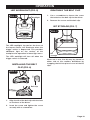
INSTALLING BITS (Fig. 8)
FIG. 8
REMOVING BITS (Fig. 8)
WARNING: Use protective gloves
when removing the bit from the tool, or first
allow the bit to cool down. The bit may be
hot after prolonged use.
1. Lock the trigger switch by placing the
direction-of rotation selector in the OFF
(center) position.
2. Pull the sleeve towards the front of the
tool and hold it in place.
3. Remove the bit from the hexagonal hole
in the bit retainer.
1. Lock the trigger switch by placing the
direction-of-rotation selector in the OFF
(center) position.
2. Pull the sleeve toward the front of the
tool and insert the 1/4-in. bit into the
chuck.
3. Release the sleeve and let it return to its
original position.
4. Pull the bit to check if it installed
securely.
WARNING: If the sleeve does not
return to its original position, the bit is not
correctly installed. Retry until the bit is
properly installed.
NOTICE: When the bit diameter is larger
than 1/4 in., use a suitable adapter (available
separately) to install the bit.
Page 11
4. Release the sleeve.
TIGHTENING AND LOOSENING
SCREWS AND NUTS
1. Install the correct bit.
2. Apply just enough pressure to keep the
bit engaged on the screw or nut.
3. Apply minimal pressure to the trigger
switch initially. Increase the speed only
when full control can be maintained.
NOTICE: This driver is equipped with
an electric brake. When the brake is
functioning properly, sparks may be visible
through the vent slots in the housing. This is
normal and is the action of the brake.