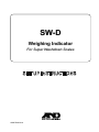
1
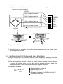
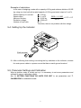
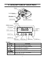
SW-D
Weighing Indicator
For Super Washdown Scales
1WMPD4002414
Warning Definition
The warning described in this manual has the following meaning:
DANGER
An imminently hazardous situation which, if not avoided, will result
in death or serious injury.
© 2011 A&D Company, Limited. All rights reserved.
No part of this publication may be reproduced, transmitted, transcribed, or translated into any
language in any form by any means without the written permission of A&D Company, Limited.
The contents of this manual and the specifications of the instrument covered by this manual are
subject to change for improvement without notice.
CONTENTS
1. COMPLIANCE ..................................................................................................... 2
2. INTRODUCTION .................................................................................................. 3
3. FEATURES........................................................................................................... 3
4. UNPACKING ........................................................................................................ 4
5. INSTALLATION and PRECAUTIONS.................................................................. 5
5.1. Precautions for Installing the Indicator....................................................... 5
5.2. Connecting to the load cell ........................................................................ 5
5-3. Verifying Load Cell Output and Input Sensitivity........................................ 6
5-4. Setting Up the Indicator............................................................................. 7
5-5. Parameter Settings and Calibration .......................................................... 7
6. DESCRIPTION OF EACH PART.......................................................................... 8
7. CALIBRATION ................................................................................................... 10
7.1. Items of the calibration mode .................................................................. 10
7.2. Setting of the weighing capacity / division / decimal point position.......... 12
7.3. Gravity acceleration correction ................................................................ 13
7.4. Calibration using a weight ....................................................................... 14
8. SETTING FUNCTIONS OR UNITS FOR USE ................................................... 16
8.1. Setting of the CF function ........................................................................ 16
8.2. Setting unit for use .................................................................................. 17
8.3. CF Function list ....................................................................................... 18
9. OPTIONS ........................................................................................................... 19
9.1. SW-11 Display stand / Wall-mount .......................................................... 19
10. MAINTENANCE ............................................................................................... 20
10.1. Notes on maintenance........................................................................... 20
10.2. Error codes............................................................................................ 20
11. SPECIFICATIONS ............................................................................................ 21
11.1. Specifications......................................................................................... 21
11.2. External dimensions .............................................................................. 22
GRAVITY ACCELERATION MAP .......................................................................... 23
1
1. COMPLIANCE
Compliance with FCC rules
Please note that this equipment generates, uses and can radiate radio frequency
energy. This equipment has been tested and has been found to comply with the
limits of a Class A computing device pursuant to Subpart J of Part 15 of FCC rules.
These rules are designed to provide reasonable protection against interference
when equipment is operated in a commercial environment. If this unit is operated in
a residential area it might cause some interference and under these circumstances
the user would be required to take, at his own expense, whatever measures are
necessary to eliminate the interference.
(FCC = Federal Communications Commission in the U.S.A.)
Classification of protection provided by enclosures
The equipment is designed to comply with the IP Code of IEC 60529.
The “IP69K” is explained as follows:
“IP”
International Protection.
“6”
Against ingress of solid foreign objects.
Dust-tight. No ingress of dust.
“9K”
Against ingress of water with harmful effects.
High pressure water jets directed against the enclosure from any direction
shall have no harmful effects. (DIN40050 Part 9)
2
2. INTRODUCTION
This manual describes how this product works and how to get the most out of it in terms
of performance.
The SW-D weighing indicator may be used to build a water-proof digital scale to
specification IP69K. It has similar specifications and functions as an indicator of the SW
series.
Please refer to the instruction manual for the SW supplied with the SW-D.
3. FEATURES
The SW-D weighing indicator is an electronic display instrument used to build a waterproof scale to specification IP69K by the combination of the SW-D and a weighing unit
(Load cell), with the following features:
Dust-tight and water-tight construction, complying with IP69K.
Employing touch-sensitive keys enabled the display to be covered with a plastic
sheet, resulting in better dust-tight and water-tight performance.
When a key is touched, the corresponding LED, above that key, turns on to
indicate that the key has been touched.
A bright LED display, with a broad viewing angle.
Operating up to four 350 Ω load cells is available.
Available range selection, for the display resolution, is 1/20 to 1/60,000.
Free setting of the weighing capacity, within the display resolution of 1/60,000, is
available.
Available weighing units are kg (kilogram), g (gram), Ib (pound), oz (ounce), and pcs
(pieces for the counting mode).
The counting mode easily counts the number of objects of the same weight.
The comparator mode compares the displayed value (weight value) with the
previously set comparator values and indicates the results by the large and bright
LED display. The optional comparator relay output (SW-03) can output the results
as a relay signal.
The auto-tare function, used with the comparator mode, automatically tares and
displays “OK” for a certain amount of sample and repeats this process for the next
weighing.
Using the optional RS-232C serial interface (SW-03) or optional RS-422/485 serial
interface (SW-04) provides serial data output of the weight value and relay output of
the comparison result.
The optional sealed lead acid (SLA) battery (HC-02i) can be installed, allowing the
scale to be used where an AC power source is not available.
SW-11 provides the function of a display stand or wall-mount bracket for the SW-D.
3
4. UNPACKING
Unpack the indicator carefully and keep the packing material if you are likely to
transport the indicator again in the future.
When unpacking, check whether all of the following items are included:
Model label
(1083013259-2)
Indicator
To be attached. SW-D
CAPACITY SECTION
Write the scale’s ratings, etc..
SW-D
Set up instructions
(this manual)
SW series
Instruction manual
Main power cord
Please confirm that the main
power type is correct for your
local voltage and receptacle.
4
SW-D
SW series
SET UP INSTRUCTIONS
INSTRUCTION MANUAL
5. INSTALLATION and PRECAUTIONS
5.1. Precautions for Installing the Indicator
DANGER
Ground the indicator so that the user will not be subjected an electric shock.
Do not handle the main power cord with wet hands.
The AC plug is not water-resistant. Install it in an area where it does not get
wet.
Even when the optional sealed lead acid (SLA) battery (HC-02i) is used, be
sure to prevent the AC plug from getting wet.
Do not install the indicator where there is flammable or corrosive gas present.
Do not pull, fold or arrange cables forcibly.
Use shielded cables for all connections.
Ground the platform to be connected to the indicator to avoid a risk of electric
shock.
Read the section “PRECAUTIONS” in the instruction manual of the SW to
understand the conditions and precautions for installation, operation and cleaning
the indicator.
5.2. Connecting to the load cell
1. Disconnect the main power cord of the scale from the power source.
2. On the bottom of the display, remove the screw protection caps on the load cell
panel. Loosen the four screws and open the load cell panel.
3. Loosen the cable clamp locking nut on the load cell panel and insert the load cell
cable through the cable clamp.
Accommodates load cell cable diameters of φ3.5 to 7.0 mm.
Load cell
cable
Locking
nut
Cable
clamp
Load cell
panel
5
4. Solder the wires to the pin contacts of the connector.
A 5 m or less load cell cable is recommended as the SW-D uses a 4 wire
system (no remote sensing).
SHIELD
(EXC-) Negative Excitation
(SIG-) Negative Signal In
(SIG+) Positive Signal In
(EXC+) Positive Excitation
Load cell
Load cell cable
5
SHIELD
4
EXC-
3
SIG-
2
SIG+
1
EXC+
Pin contacts
5. Tighten the cable clamp locking nut to secure the load cell cable.
6. Close the load cell panel by securing the four screws and cover the screws using
the screw protection caps.
5-3. Verifying Load Cell Output and Input Sensitivity
The input sensitivity is 0.2 µV/division or more. When designing a weighing scale, the
following calculation formula should be satisfied.
The input sensitivity requires a change in output voltage, from the weighing device,
to change the display value as a one digit step. In order to achieve a scale with
stable performance, select the input sensitivity as large as possible.
Calculating formula:
0.2 ≤
E× B×d
A×n
A:
B:
d :
E:
n:
Rated capacity of load cell
Rated output (mV/V)
Minimum division
Excitation voltage (mV) = 5000 mV for SW-D
Number of load cells
6
Example of calculation:
In the case of designing a scale with a capacity of 60 kg and minimum division of 0.005
kg, using one load cell with a rated capacity of 100 kg and rated output of 1 mV/V:
Rated capacity of Load cell:
Rated output:
Minimum division:
Excitation voltage:
Number of load cells:
A = 100 kg
B = 1 mV/V
5000 × 1 × 0.005
= 0.25 > 0.2
d = 0.005 kg
100
×
1
E = 5000 mV
n=1
Therefore, there is no problem with this design.
5-4. Setting Up the Indicator
Earth terminal
After confirming that nothing is touching the key switches on the indicator, connect
the main power cable to a power source that has an earth ground terminal.
5-5. Parameter Settings and Calibration
When a platform scale is initially set up, it is necessary to set some parameters and
calibrate it using a calibration weight.
See “8. SETTING FUNCTIONS OR UNITS FOR USE” to set parameters and “7.
CALIBRATION” to calibrate the scale.
7
6. DESCRIPTION OF EACH PART
Display
Load cell panel
Main power cord
Earth terminal
Load cell connector
LED display
STABLE indicator
NET indicator
LO
OK
HI
pcs
ZERO indicator
Weighing
units
g
STABLE
NET
kg
ZERO
oz
lb
ON/OFF key
ON/OFF
SAMPLE
PRINT
UNITS
ZERO
TARE
SAMPLE key
PRINT key
UNITS key
ZERO key
TARE key
Symbols
Symbol
Description
STABLE ○
Turns on when the weight value is stable.
NET ○
Turns on when the NET weight is displayed.
(The tare operation is in progress.)
ZERO ○
Turns on when zero is displayed.
Turns on when the comparator results are displayed.
Weighing units
“pcs”, “g”, “kg”, “oz” and “lb” are available.
A selected unit turns on.
8
Key
Description
ON/OFF key
Turns the power ON or OFF.
When turned ON, the scale will be automatically set to zero (power-on zero).
To turn the power OFF, press and hold the key.
Note: If pressing the key does not turn the power ON immediately, keep
pressing the key.
SAMPLE key
In the counting mode (“pcs”), goes to the unit weight storing mode.
Press and hold to go to the comparator value setting mode.
PRINT key
Outputs the weight value to the printer.
In the setting mode, this key is used to increase the value of the selected
blinking digit by one.
UNITS key
Switches the weighing unit.
In the setting mode, this key is used to shift the blinking digit to the right.
ZERO key
Zeroes the scale and sets the display to zero.
TARE key
Subtracts the tare (container) weight placed on the weighing pan.
In the setting mode, this key is used to store the setting value and proceed to
the next step.
9
7. CALIBRATION
When calibrating, refer to this set up instructions. (The contents of SW instruction manual
are not the same as this set up instructions.)
7.1. Items of the calibration mode
The calibration mode has the following three functions.
• Setting of the weighing capacity, minimum division, and decimal point position.
• Gravity acceleration correction
• Calibration using a weight
How to enter the calibration mode
1. Make sure that the scale is in the weighing mode (displaying “kg”, “g”, “lb”, “oz” or
“pcs”).
2. Remove the screw protection caps on the load cell panel on the bottom of the
display. Loosen the four screws and then open the load cell panel. The calibration
(CAL) switch is located inside.
3. Press the CAL switch. The indicator displays “Cal5et”. (And proceed to “7.2”, “7.3”,
or “7.4”.)
Calibration (CAL) switch
Load cell panel
10
The chart below shows the relation between each item and the key operation in the
calibration mode.
Weighing mode
Press the (CAL)
switch
Setting of the weighing
capacity, minimum division,
and decimal point
Gravity acceleration
correction
Calibration using a weight
Setting of the CF function
Press
or
Power OFF
Press the UNITS key to select an item and press the TARE key to execute it.
To exit from the calibration mode, press the ZERO1 key or the CAL switch. The
indicator turns the power off. (Or press the ON/OFF key to turn the power off.)
11
7.2. Setting of the weighing capacity / minimum division / decimal point position
Set the weighing capacity, minimum division, and decimal point position. Be sure to
perform these setting first when connecting to a load cell (base unit). The indicator does
not require setting each time, if nothing is to be changed.
1.Refer to “7.1. Items of the calibration mode”, to enter the
calibration mode. The indicator displays “Cal5et”.
2. Press the TARE key to enter the setting mode of
the weighing capacity, minimum division, and decimal
point position.
3. The indicator displays the currently set minimum
division and calibration unit. (Display example: “d-1
kg”) The blinking digit indicates the minimum
division. Press the PRINT key to select 1, 2, or 5.
The unit indicates the calibration unit. Press the
SAMPLE key to select either “kg” or “lb”.
Press the TARE key to store the currently set
minimum division and calibration unit, and proceed to
the next step.
Press
Press
Press
4. After displaying “Cap”, the indicator displays the
currently set weighing capacity and decimal point
position. (Display example: “0060.00 kg”) Set the
weighing capacity and decimal point position using
the following keys:
MODE
PRINT
Shift the blinking digit to the right.
Increases the number (+1) at the
blinking digit.
SAMPLE
Shift the decimal point position.
Press
Press the
TARE
key to store the currently
displayed weighing capacity and decimal point
position, and proceed to the next step.
Available setting range of the resolution is 60,000 or
less. The resolution is the value that divides the
weighing capacity by the minimum division.
(Decimal point position is ignored.)
5. After displaying “end”, the indicator displays “Cal5et”,
and the setting is complete.
After setting the weighing capacity, minimum division, and decimal point position, be
sure to perform “7.4. Calibration using a weight”.
12
7.3. Gravity acceleration correction
When the scale is first used or has been moved to another location, it should be
calibrated using a calibration weight.
But if a calibration weight is not available, the gravity acceleration correction will
compensate the scale. Change the gravity acceleration value stored in the scale to the
value of the area where the scale will be used. Refer to the gravity acceleration map at
the end of this manual.
Note: Gravity acceleration correction is not required when the scale will be
calibrated using a calibration weight at the place where it is to be used.
1. Refer to “7.1. Items of the calibration mode”, to enter the
calibration mode. The indicator displays “Cal5et”.
2. Press the UNITS key to display “g 9.7985” (gravity
acceleration value).
3. Press the TARE key to enter the gravity acceleration
value setting mode.
Press
Press
4. Change the displayed value using the following keys.
UNITS
To shift the blinking digit to the right.
PRINT
To increase the value of the blinking digit
by one.
5. Press the TARE key. The setting value is stored and
“end” is displayed. After displaying “g 9.7985” (gravity
acceleration value), the setting is complete.
6. When calibration using a calibration weight is to be
performed, go to step 3 of “7.4. Calibration using a
weight”.
To finish the setting procedure, press the ZERO1 key or
the CAL switch. The indicator turns the power off.
13
Press
Press
7.4. Calibration using a weight
This function adjusts the scale (indicator) for accurate weighing.
Calibration must be done when the SW-D is initially connected to a load cell (base unit)
or the combination is changed.
Calibration may also be required according the changes in the environment.
When the scale (indicator) has been moved.
When the ambient environment has significantly changed.
For regular calibration.
Note: Prepare a weight, preferably a weight with the same value as the weighing
capacity of the scale to be calibrated. Note that the calibration weight value
can be changed.
1. Turn the power ON and warm up the scale for at least half an hour.
Change the function setting “poff” or place something on the weighing pan to
disable the auto power-off function.
2. Refer to “7.1. Items of the calibration mode”, to enter
the calibration mode. The indicator displays “Cal5et”.
3. Press the
UNITS
key twice and display “Cal”.
4. Press the TARE key. “Cal 0” is displayed. Confirm
that nothing is placed on the weighing pan and wait for the
STABLE indicator to turn on.
5. Press the TARE key. The scale calibrates the zero
point and displays the value of the calibration weight
(SPAN calibration).
Press
twice
Press
The calibration weight value is equal to the weighing
capacity. (factory setting)
If you want to calibrate only the zero point without
calibrating SPAN, press the ZERO1 key. After
“end” is displayed, go to step 9.
6. To calibrate with a weight different from the
weighing capacity, change the displayed value
using the following keys.
UNITS
To shift the digit that is blinking
to the right.
PRINT
To increase the value of the
blinking digit by one.
Using a weight with the same value as the
weighing capacity is recommended. If other
weights are used, use one with a value greater
than two-thirds of the capacity.
14
Press
Press
Calibration
weight
Weighing pan
7. Place the calibration weight with the same value
as displayed on the weighing pan, and wait for
the STABLE indicator to turn on.
8. Press the TARE key. The scale calibrates SPAN and
“end” is displayed. After displaying “Cal”, the setting is
complete.
Press
9. To finish the setting procedure, press the ZERO1 key or
the CAL switch. The indicator turns the power off.
Note: If the scale will be moved to another location, set the gravity acceleration
value for the new location and calibrate the scale according to the procedure
above. Refer to the previous section to set the gravity acceleration value.
15
8. SETTING FUNCTIONS OR UNITS FOR USE
The indicator has CF function settings to specify the indicator performance.
After installing the indicator, the indicator does not require resetting or changing of this
CF function as far as it is used normally.
If you want to maintain only the needed units, set using this function.
The parameters set in the CF function settings and unit setting are maintained even if the
power is turned OFF.
Item
Parameter
8.1. Setting of the CF function
1. Refer to “7.1. Items of the calibration mode”, to enter the
calibration mode. The indicator displays “Cal5et”.
2. Press the MODE
3. Press the TARE
key three times to display “Cf”.
Press
three times
key to display the setting item.
4. Select the setting item and parameter using the following keys:
UNITS
Proceed to next setting item.
PRINT
Increases the number (+1) at the blinking digit.
(Change the parameter)
When the currently stored set is changed, the STABLE
indicator “●” turns off.
Changing the parameter using the PRINT key at CF1,
2, 8 or 12 is not available.
5. Press the TARE
key to store the setting. After displaying
“end”, the indicator displays “Unit” and proceeds to the unit
setting mode.
To proceed, without storing the CF function setting, press
the ZERO
6.
key. After displaying “Unit”, proceed to the
use unit setting mode. (Display example: “1110000 pcs”)
When the unit setting is to be performed, go to step 5 of
“8.2. Setting the unit for use”.
When the unit setting is not to be performed, press the
ZERO1 key. After displaying “Cf”, the setting is complete.
To adjust to the designed scale specification, set other
items by following the procedure described above.
16
Press
Press
Press
8.2. Setting unit for use
1.Refer to “7.1. Items of the calibration”, to enter the
calibration mode. The indicator displays “Cal5et”.
2. Press the MODE
3. Press the TARE
Press
three times
key three times to display “Cf”.
key to display the setting item.
Press
4. To proceed without storing this setting item, press the
ZERO key.
After displaying “Unit”, proceed to the unit setting mode.
(Display example: “1110000 pcs”)
Press
5. Select the unit to be used, using the following keys.
UNITS
Select the unit (Shift the blinking unit to the
right)
PRINT
Set whether the selected unit is available (0)
or not available (1). (Change the number of the
blinking digit to “0” or “1”.)
About the unit setting mode
Each of the display digits are assigned to a unit setting.
(The setting at the first and fourth digit is not available.)
Display
assignment
7
6
5
4
3
2
1
Unit
pcs
g
kg
Set
disabled
oz
lb
Set
disabled
Press
-The unit during selection is indicated.
-With each digit, if setting to “0”, its unit is not available, and
if setting to “1”, its unit is available.
(Only when set to “1”, is a unit available.)
Even if a unit is stored, availability for use depends on the
weighing capacity and resolution.
Example) When setting to “1010000 pcs”, only “pcs”
and ”kg” are available as units.
6. Press the
TARE
key to store the setting. After displaying
“end”, the indicator displays “Cf”, and the setting is complete.
If you want to proceed without storing the setting of the unit
setting mode, press the ZERO
the setting is complete.
key. After displaying “Cf”,
17
Press
8.3. CF Function list
Item
Used internally
Parameter
Cf 1
3
Not available for setting change
Used internally
Cf 2
0
Not available for setting change
Zero tracking
0
1
0
Not available for setting of function
“trc” (It is fixed to “trc 1”)
Available for setting of function “trc”
None
±10% of weighing capacity
±50% of weighing capacity
±100% of weighing capacity
Tare by displayed division
Tare by internal count
During tare, stable indicator has no
function
During tare, stable indicator turns on
Tare is not cleared by zero operation
Cf 7
1
Tare is cleared by zero operation
Used internally
Cf 8
3
Not available for setting change
Minus and
printing limit
0
Non-limit
Cf 9
1
Limit has function
Auto tare function
0
No auto tare function
1
Auto tare function
0
Cf 3
Power on zero
range
Cf 4
Calculation of tare
Cf 5
Stable indicator of
during tare
Cf 6
Tare clear by
zero operation
Cf10
Stable detection
range
1
0
1
2
3
0
1
0
Description
Cf11
1
Not available for setting of function
“5t-b” (It is fixed to “5t-b 0”)
Available for setting of function “5t-b”
Used internally
0
Not available for setting change
Cf12
When “Cf 3 0”, “trc”
has no function.
Calibration zero
reference
Refer to below note.
When “Cf10 0”, “at”
“at-t” “at-f” has no
function.
When “Cf11 0”, “5tb” has no function.
Factory setting
Note: About minus and printing limit setting (“Cf 9”)
When setting “Cf 9” to “1”, the indicator has the following limit.
When the total weight is -19d or less, the indicator displays “-e”.
(*d = minimum division)
When the total weight is minus, the indicator does not perform the printing.
18
9. OPTIONS
For details of HC-02i, SW-03, and SW-04, refer to the “OPTIONS” in the SW series
instruction manual.
9.1. SW-11 Display stand / Wall-mount
SW-11 provides the function as a display stand or a wall-mount for the SW-D.
Attaching to SW-11
1. Attach the SW-11 to the display using the four screws provided.
2. Adjust the display angle using the two clamps on the SW-11.
After loosening the two clamps on the SW-11, adjust the display angle, and retighten the two clamps.
Clamp
SW-11
3. If you want to use the SW-11 as wall-mount bracket, after fixing only the stand part of
the SW-11 on the flat wall by using the screws, attach the display to the SW-11.
(These screws are not provided.)
For details of the installing dimension, refer to “11.2. External dimensions”.
19
10. MAINTENANCE
10.1. Notes on maintenance
Do not disassemble the indicator. Contact your local A&D dealer if the indicator
needs service or repair.
Use the original packaging for transportation.
Do not use organic solvents to clean the indicator. Use a warm lint free cloth
dampened with a mild detergent.
Calibrate the indicator periodically to maintain the weighing accuracy.
10.2. Error codes
Overload error
Indicates that an object beyond the weighing capacity
has been placed on the weighing pan.
Remove the object from the weighing pan.
Over range error
When setting “Cf 9” to “1”, indicates that total weight is
–19d or less. (d = minimum division)
(In the case of turning on the stable indicator, setting the
display to zero by pressing the ZERO key is available.)
Unit weight error
Indicates that the sample weight is too light to set the unit
weight in the counting mode.
CAL error
Indicates that the calibration procedure is canceled
because the calibration weight is too light.
Check that the weighing pan is installed properly and the
mass of the calibration weight.
Low battery
Indicates that the HC-02i battery is depleted.
Charge the battery immediately.
Other
There may be an internal malfunction.
(∗ indicates an error number.)
Note: If the error persists or other errors occur, contact your local A&D dealer.
20
11. SPECIFICATIONS
11.1. Specifications
Input sensitivity
Input signal range
Load cell excitation
voltage
Load cell drive capacity
Temperature Zero
coefficient
Span
linearity
Maximum display
resolution
Display
Display update
Operating temp.
Power supply
Dimension
Weight
0.2 µV / d min. (d: minimum division)
-16 mV ~ 16 mV
5 V DC ±5% (no remote sensing)
Up to 4 x 350 ohm load cells
±(0.2 µV ±0.001% of zero adjustment voltage) / °C (typ.)
±0.001% / °C of reading (typ.)
±0.01 % of full scale
60,000
Weight display: 7 segment LED display (Character height 14.6 mm)
Comparison result: red / yellow / green / yellow / red LED
Approximately 10 times per second
-10°C ~ 40°C / 14°F ~ 104°F
AC main (100V +10%/-15%, 50/60 Hz 20VA)
or SLA Battery (option), available use time approximately 70
hours*
Main power cord length: Approximately 3 m
255 (W) x 119 (D) x 179 (H) mm
Approximately 2.1 kg
* In the case of one 350 ohm load cell, no other option, and turning on comparator LED
(The available use times depend on the condition of the battery, how the battery is used
and the environment.)
Options
HC-02i
SLA Sealed Lead Acid battery (YUASA NP4-6 recommended)
SW-03
RS-232C / Relay output
SW-04
RS-422 / 485
SW-11
Display stand / Wall-mount
Note: The options, SW-03 and SW-04, can not be used at the same time.
21
11.2. External dimensions
255
118.9
160
47.5
20.5
52.5
158
50
52.5
47.5
4-M4 depth 8mm
● When attaching to SW-11
315
135.9
65
50
152.5
197.5
90
283
6-φ5
160
4-M4 x 8 truss screw
110
70
250
Unit: mm
22
GRAVITY ACCELERATION MAP
Values of gravity at various locations
Amsterdam
Athens
Auckland NZ
Bangkok
Birmingham
Brussels
Buenos Aires
Calcutta
Cape Town
Chicago
Copenhagen
Cyprus
Djakarta
Frankfurt
Glasgow
Havana
Helsinki
Kuwait
Lisbon
London (Greenwich)
Los Angeles
Madrid
9.813 m/s2
9.807 m/s2
9.799 m/s2
9.783 m/s2
9.813 m/s2
9.811 m/s2
9.797 m/s2
9.788 m/s2
9.796 m/s2
9.803 m/s2
9.815 m/s2
9.797 m/s2
9.781 m/s2
9.810 m/s2
9.816 m/s2
9.788 m/s2
9.819 m/s2
9.793 m/s2
9.801 m/s2
9.812 m/s2
9.796 m/s2
9.800 m/s2
Manila
Melbourne
Mexico City
Milan
New York
Oslo
Ottawa
Paris
Rio de Janeiro
Rome
San Francisco
Singapore
Stockholm
Sydney
Taichung
Tainan
Taipei
Tokyo
Vancouver, BC
Washington DC
Wellington NZ
Zurich
23
9.784 m/s2
9.800 m/s2
9.779 m/s2
9.806 m/s2
9.802 m/s2
9.819 m/s2
9.806 m/s2
9.809 m/s2
9.788 m/s2
9.803 m/s2
9.800 m/s2
9.781 m/s2
9.818 m/s2
9.797 m/s2
9.789 m/s2
9.788 m/s2
9.790 m/s2
9.798 m/s2
9.809 m/s2
9.801 m/s2
9.803 m/s2
9.807 m/s2
World map
24