1
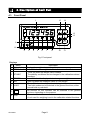
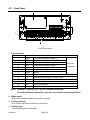
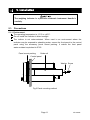
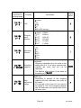
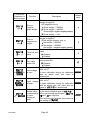
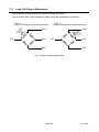
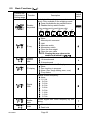
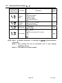
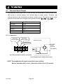
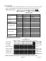
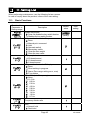
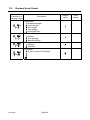
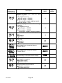
AD-4408A Weighing Indicator for Field Networks INSTRUCTION MANUAL 1WMPD4001973 WARNING DEFINITIONS The warnings described in this manual have the following meanings: A potentially hazardous situation which, if not avoided, could result in death or serious injury. A potentially hazardous situation which, if not avoided, may result in minor or moderate injury or damage to the instrument. This symbol indicates caution against electrical shock. Do not touch the part where the symbol is placed. This symbol indicates the ground terminal. This symbol indicates that an operation is prohibited. NOTE Information or cautions to use the device correctly. © 2009 A&D Company, Limited. All rights reserved. No part of this publication may be reproduced, transmitted, transcribed, or translated into any language in any form by any means without the written permission of A&D Company, Limited. The contents of this manual and the specifications of the instrument covered by this manual are subject to change for improvement without notice. Anybus-CompactCom is a registered trademark of HMS Industrial Networks. Contents 1. Safety Precautions .......................................................................................................3 2. Introduction...................................................................................................................4 3. Specifications ...............................................................................................................5 3.1. Analog Section ....................................................................................................5 3.2. Digital Section .....................................................................................................5 3.3. General ...............................................................................................................6 3.3.1. Interface...................................................................................................................................... 6 3.3.2. Measuring functions ................................................................................................................... 6 3.3.3. Other........................................................................................................................................... 7 3.3.4. Accessories ................................................................................................................................ 7 4. Description of Each Part ...............................................................................................8 4.1. Front Panel .........................................................................................................8 4.2. Rear Panel ........................................................................................................10 5. Installation ..................................................................................................................11 5.1. Precautions .......................................................................................................11 5.1.1. Environment.............................................................................................................................. 11 5.1.2. Power source............................................................................................................................ 12 5.2. Load Cell Connection........................................................................................13 5.3. Interface Module Installation .............................................................................14 6. Operation....................................................................................................................15 6.1. General Function...............................................................................................15 6.1.1. Zero adjustment........................................................................................................................ 15 6.1.2. Zero tracking............................................................................................................................. 15 6.1.3. Tare .......................................................................................................................................... 16 6.1.4. F key ......................................................................................................................................... 16 6.1.5. display .................................................................................................................................. 17 6.1.6. Memory backup ........................................................................................................................ 17 6.2. Mode Map .........................................................................................................18 7. Calibration ..................................................................................................................19 7.1. General Description ..........................................................................................19 7.2. Calibration With an Actual Load (Cal5et).........................................................20 7.3. Calibration-Related Functions (Calf)................................................................22 7.4. Calibration Errors ..............................................................................................28 7.5. Load Cell Output Adjustment ............................................................................29 8. General Functions ......................................................................................................30 8.1. Setting Procedure .............................................................................................30 Page 1 AD-4408A 8.2. Basic Functions (fncf) .....................................................................................32 8.3. Standard Serial Output (Cl f) ..........................................................................33 9. Interface......................................................................................................................34 9.1. Standard Serial Output......................................................................................34 9.1.1. Connection................................................................................................................................ 34 9.1.2. Output data ............................................................................................................................... 35 9.1.3. Data transfer mode................................................................................................................... 36 10. Maintenance ...............................................................................................................37 10.1. Error Messages...............................................................................................37 10.2. Check Mode ....................................................................................................37 10.2.1. Entering the check mode........................................................................................................ 37 10.2.2. Checking the key switches ..................................................................................................... 38 10.2.3. Checking the standard serial output....................................................................................... 38 10.2.4. Checking interfaces ................................................................................................................ 39 10.2.5. Checking the testing terminal ................................................................................................. 39 10.2.6. Checking the A/D (load cell) ................................................................................................... 39 10.2.7. Checking the internal count .................................................................................................... 39 10.2.8. Checking the program version................................................................................................ 39 10.2.9. Checking the serial number.................................................................................................... 39 10.2.10. Checking the program checksum......................................................................................... 39 10.2.11. Checking the FRAM checksum ............................................................................................ 40 10.2.12. Checking the calibration-related functions ........................................................................... 40 10.3. Initialization Mode ...........................................................................................41 10.3.1. RAM initialization / General functions initialization ................................................................. 41 10.3.2. All data initialization ................................................................................................................ 42 11. Setting List..................................................................................................................43 11.1. Basic Functions...............................................................................................43 11.2. Standard Serial Output....................................................................................44 11.3. Calibration-Related Functions .........................................................................45 12. External Dimensions...................................................................................................47 AD-4408A Page 2 1. Safety Precautions For safe and correct usage, read the following precautions carefully before using the indicator. Grounding located on the rear Earth ground the indicator by connecting the earth ground terminal panel to the earth, to prevent a fire, electrical shock or indicator malfunction. Do not share the ground line with other electrical power equipment. Appropriate power cable Use a power cable appropriate to the supply voltage and current used. Using an inappropriate cable may cause electrical leakage or a fire. Connect the power cable to the terminals firmly using compression lugs. Fuse replacement A fuse is provided to protect against a short circuit and possible fire hazard. The indicator is equipped with various protection circuits and the fuse should not burn out under normal operations. If the fuse burns out, the internal circuits may have been damaged by surges. Do not try to replace the fuse. Contact the nearest A&D dealer. Avoid water and moisture The indicator is not water-resistant. Securing the front panel to the control panel using the accessory panel mount packing will provide the indicator with IP-65 protection. Avoid an environment with flammable gases Do not use the indicator in places where flammable gases are present. Indicator overheat To prevent the indicator from overheating, allow appropriate clearance between the peripheral devices. If the ambient temperature exceeds the specified operating temperature, use a fan to cool the environment. Page 3 AD-4408A 2. Introduction The AD-4408A is a weighing indicator that amplifies signals from a load cell, converts it to digital data and displays it as a weight value. Connection to various field networks is possible by installing the interface module into the option slot. • For details on applicable field networks, visit our website. • Download the instruction manual for each interface from our website. (Memory map and check modes vary with the interface.) • The interface module used is the Anybus-CompactCom network interface module, manufactured by HMS Industrial Networks. • The interface module is available as an accessory for the AD-4408A. Purchase the interface module from A&D, or directly from an iterface module supplier. The accessory panel mount packing will provide the indicator with IP-65 protection. This indicator has the following performance: Input sensitivity: ......................... 0.15 μV /d Display resolution: ..................... 999,999 d max. (Less than 20,000 d recommended) Sampling rate:............................ 100 times/second Input voltage range: ................... -35 mV to +35 mV (-7 mV/V to +7 mV/V) Digital span mode: Keying in the load cell output voltage (mV/V) allows calibration to be performed without an actual load. NOTE: The unit, d indicates a minimum division. AD-4408A Page 4 3. Specifications 3.1. Analog Section Input sensitivity Input voltage range Zero adjustment range Load cell excitation voltage Load cell drive capacity Temperature Zero coefficient Span Non-linearity A/D conversion method A/D resolution count Display resolution Sampling rate 3.2. 0.15 μV/d or greater -35 mV to +35 mV (-7 mV/V to +7 mV/V) -35 mV to +35 mV (-7 mV/V to +7 mV/V) 5VDC 5%, 120 mA with remote sensing capability Maximum 8 x 350 Ω load cells 0.02 μV /°C typ., 0.1 μV /°C max. 3ppm /°C typ., 15ppm /°C max. 0.005 % of full scale Delta-sigma method Approximately 16,000,000 counts 999,999 d max. (Less than 20,000 d recommended) 100 times/second Digital Section Display element Measurement display Status indicators Key switches • Measurement display: 6-digit 7-segment green LED • Character height: 14.6 mm • Polarity display: 1 green LED • Status indicators: 6 red LEDs • Switches between NET and GROSS • Selectable decimal places (101, 102, 103, 104, 105) • Overflow display All the digits turn OFF. (When the polarity is negative, the minus sign appears at the highest-order digit.) ZERO, STABLE, GROSS, NET, HOLD, ZERO, TARE, NET/GROSS, F, ON/OFF, ENTER, CAL Page 5 AD-4408A 3.3. General 3.3.1. Interface Standard serial output Option slot Output for communication with A&D peripheral devices (20 mA current loop) Connection to various field networks is possible by installing the interface module into the option slot. For details on applicable field networks, visit our website. 3.3.2. Measuring functions Zero adjustment Zero tracking Tare Stability detection Digital filter AD-4408A • Sets the gross weight to zero by pressing the ZERO key. • Selection of disable or enable for the operation when unstable. • The zero value is stored in the non-volatile memory. • Zero adjustable range Can be set optionally in the range of 1 to 100% of the weighing capacity. • Tracks the weight drift around the zero point to maintain zero. • Zero tracking time 0.0 to 5.0 seconds (Can be set optionally within the range.) • Zero tracking band 0.0 to 9.9 d (Can be set optionally within the range.) • Sets the net weight to zero by pressing the TARE key. • Selection of disable or enable for the operation when unstable or negative. • The tare weight is stored in the non-volatile memory. • Tare range: Gross weight ≤ Weighing capacity • Turns ON the stabilization indicator when the variables of the weight values per sampling are within the set band in the set time. • Stability detection time 0.0 to 9.9 seconds (Can be set optionally within the range.) • Stability detection band 0 to 9 d (Can be set optionally within the range.) Cutoff frequency range (-3dB) : 0.7 to 11 Hz Page 6 3.3.3. Other Power source Power consumption Operating temperature Operating humidity Installation method Mass • Zero value, tare weight, calibration data and function data are written into the FRAM. • Data retention time is 10 years or more. 100 VAC to 240 VAC, +10%, -15%, (50/60 Hz) Approximately 10 VA -10°C to +40°C 85% R.H. or less (no condensation) Panel mount Approximately 800 g 3.3.4. Accessories Item Weighing capacity plate Unit label Panel mount packing Terminal block cover Quantity 1 1 1 1 Data backup against power failures Model name 108-4023454 108-4023456 106-4004213 107-4005384 Page 7 AD-4408A 4. Description of Each Part 4.1. Front Panel 1 15 14 ZERO TARE 13 12 Net/B/G NET GROSS ZERO STABLE GROSS NET HOLD 9 ON/OFF ESC ENTER 10 11 CAL 16 2 3 4 5 6 7 8 Fig.1 Front panel Displays No. Name 1 Main display 2 ZERO 3 STABLE 4 5 GROSS NET 6 HOLD 7 8 UNIT AD-4408A Description Displays the weight value, setting values, error messages, etc. Turns ON when the weight value is in the center of zero. • Turns ON when the weight value is stable. • The stability conditions can be changed in the calibration-related functions. Turns ON when the displayed value is a gross weight. Turns ON when the displayed value is a net weight. • Turns ON when the weight value is being held. • Two hold modes can be selected in the general functions, either normal hold or peak hold. The function for this indicator can be selected in the general functions, depending on the purpose. • Place a unit label. • A unit used for weighing is set in the calibration-related functions. Page 8 Key switches No. Name 9 10 11 CAL ON/OFF ESC ENTER Net/B/G NET GROSS 14 TARE 15 ZERO 16 • The key to proceed to the selected mode. • Confirms the setting value and stores the data when pressed after a setting is changed. • The function for this key can be selected in the general functions, from the list below: No function Manual print command Hold Alternate switch Momentary switch Clear the tare weight Clear the zero value • The key decreases the value of the blinking digit by one when the numerical values are being entered. 12 13 Description • The key to enter the calibration mode. • The key is concealed by a sealable cover. To avoid unintentional operations, keep the cover attached except when entering the calibration mode. • The key to turn the indicator ON (Weighing mode) and OFF (OFF mode). • When OFF, all of the displays and external output/input devices are turned OFF, but a decimal point located at the right side of the main display remains ON. • The key functions as an ESC key when the numerical values are being entered. Seal • The key to switch between the gross weight and the net weight. • The key increases the value of the blinking digit by one when the numerical values are being entered. • The key to perform tare. • The tare conditions are set in the calibration-related functions. • The key shifts the position of the blinking digit to the right when the numerical values are being entered. • In the OFF mode, pressing the ON/OFF key while holding the TARE key will clear the zero value and the tare weight. • The key to zero the current display. • The zero conditions are set in the calibration-related functions. • The key shifts the position of the blinking digit to the left when the numerical values are being entered. • Can be sealed using a wire seal. Page 9 AD-4408A 4.2. Rear Panel 2 3 4 4 1 Fig.2 Rear panel 1 Terminal block Terminal No. 1 2 3 4 5 6 7 8 9 10 11 12 13 EXC+ SEN+ SENEXCSIG+ SIGSHLD C.L. C.L. F.G. E AC AC Function Load cell excitation voltage (+) Sensing input (+) Sensing input (-) Load cell excitation voltage (-) Load cell input (+) Load cell input (-) Shield Standard serial output (Current loop) Standard serial output (Current loop) Frame ground Earth ground AC power source AC power source Load cell connection NOTE: Terminals 7 (SHLD) and 11 (E) are internally connected. To avoid unintentional operations, keep the cover attached on the terminal block. 2 Blank panel Option slot inside to install the interface module. 3 Testing terminal Do not use, leave this terminal unconnected. 4 Sealing bolts Can be sealed with a wire seal. AD-4408A Page 10 5. Installation The weighing indicator is a precision electronic instrument. Handle it carefully. 5.1. Precautions 5.1.1. Environment The operating temperature is -10°C to +40°C . Do not install the indicator in direct sunlight. The indictor is not water-resistant. When used in an environment where the indicator may be exposed to splashing water, secure the front panel to the control panel using the accessory panel mount packing. It makes the front panel water-resistant equivalent to IP-65. Panel mount packing Guide rail Control panel Washer Screw Fig.3 Panel mounting method Page 11 AD-4408A 5.1.2. Power source Earth ground the indicator to prevent electrical shock or indicator malfunction. Before connecting the indicator to the power source, read the instruction manual thoroughly. Do not connect the indicator to the power source before the installation is complete. To avoid electrical shock, do not handle the power cable with a wet hand. Earth ground the indicator. Do not share the ground line with other electrical power equipment. The power requirement is 100 VAC to 240 VAC and the frequency is 50 Hz or 60 Hz. Use a stable power source free from instantaneous power failure or noise. To avoid a malfunction, do not share the power line with other devices. The output voltage of a load cell is a very sensitive signal. Keep all electrical noise sources away from the load cell and load cell cable. Use shielded I/O cables. Connect the cable shield to the F.G. terminal or the indicator housing. AD-4408A Page 12 5.2. Load Cell Connection Connect the load cell cable to the terminals as shown below. Use a 6-wire shielded cable to connect a load cell, especially when the cable is long or when summing multiple load cells, to avoid drift caused by changes in temperature. If the cable is short, a 4-wire shielded cable with terminals 1 and 2 (EXC+ and SEN+) and terminals 3 and 4 (SEN- and EXC-) connected may be used, but the error increases when summing multiple load cells and the cable is long. Load cell Load cell cable EXC+ SIG+ SIG- EXC- Shield Fig.4 Load cell connection Page 13 AD-4408A 5.3. Interface Module Installation Be sure to disconnect the AD-4408A from the power source before installing the interface module. Install the interface module as follows: Blank panel Step 1 Using a Phillips screwdriver, loosen the screws that secure the blank panel to the AD-4408A rear panel, and remove the blank panel. Step 2 Insert the interface module into the option slot as shown to the right. Step 3 Insert the interface module until it mates with the terminals of the PC board connector located in the option slot. Step 1 Step 2 Option slot Retaining screw Interface module PC board in the option slot Step 4 Using a TORX® driver (size T9), fasten the retaining screws with a tightening torque of 0.25 Nm in the clockwise direction to secure the interface module. Step 3 Tightening torque 0.25 Nm Step 4 Fig.5 Interface module installation NOTE: A TORX® driver is not provided with the AD-4408A. TORX is a registered trademark of Textron Inc. AD-4408A Page 14 6. Operation 6.1. General Function 6.1.1. Zero adjustment Zero adjustment is a function to set the gross weight to zero. It is performed by pressing the ZERO key. The zero adjustment range is set in Calf05 (zero adjustment range) and is expressed in percent of the weighing capacity with the calibration zero point as the center. Zero adjustment is disabled, even within the zero adjustment range, when the A/D converter overflow occurs. A ZERO error is output if zero adjustment is not performed. The zero value is stored in the non-volatile memory and is maintained, even if the power is disconnected. Clearing the zero value is performed using the F key assigned to clear the zero value. Alternately, apply power to the indicator while holding the TARE key, or with the indicator in the OFF mode, press and hold the TARE key and press the ON/OFF key, to clear the zero value. Functions related to zero adjustment z Calf05: Changes the zero adjustment range. (0 to 100%) z Calf10: Enables or disables zero adjustment when unstable. z Calf16: Enables or disables power-ON zero (function to zero upon power-ON). 6.1.2. Zero tracking Zero tracking is a function to track the weight drift around the zero point to maintain zero. The zero tracking time is set in Calf06 (zero tracking time) and the zero tracking band is set in Calf07 (zero tracking band). When the weight drift is within the specified ranges, zero adjustment is performed automatically. A ZERO error is not output even if zero tracking is not performed. Functions related to zero tracking z Calf06: Changes the zero tracking time. (0.0 to 5.0 seconds) z Calf07: Changes the zero tracking band. (0.0 to 9.9 d) Page 15 AD-4408A 6.1.3. Tare Tare is a function to store the gross weight as the tare value and set the net weight to zero. The tare weight is stored in the non-volatile memory and is maintained, even if the power is disconnected. Clearing the tare weight is performed using the F key assigned to clear the tare weight. Alternately, apply power to the indicator while holding the TARE key, or with the indicator in the OFF mode, press and hold the TARE key and press the ON/OFF key, to clear the tare weight. Functions related to tare z Calf10: Enables or disables tare when unstable. z Calf11: Enables or disables tare when the gross weight is negative. 6.1.4. F key Assign a function to the F key in the general functions. Functions related to the F key zfncf02: Assigns a function to the F key from the functions below: 0: None 1: Manual print command 2: Hold 3: Alternate switch (Read the description below.) 4: Momentary switch (Read the description below.) 5: Clear the tare weight 6: Clear the zero value zCalf15: Enables or disables clearing the zero value. zCalf20: Enables or disables the print command when the gross weight is negative. Alternate switch and momentary switch zBy assigning these switches to the F key, the ON/OFF status of the F key can be transmitted to the master station. This is useful when building a network or performing maintenance. zBy selecting “3: F key status” for fncf04 ( display), the ON/OFF status of the F key can be confirmed by the memory in sync with the display. zThese switches perform as below: Alternate switch Press the switch once and release the switch to turn ON or OFF. Press the switch again to turn OFF or ON. Momentary switch Only when the switch is being pressed, the F key is ON. When released, OFF. AD-4408A Page 16 6.1.5. display Assign a function to the display in the general functions. Functions related to the display zfncf04: Assigns a function to the display from the functions below: 0: None 1: Zero tracking in progress 2: Alarm (Zero range setting error, over) 3: F key status (Read the description below.) F key status zEnables when alternate switch or momentary switch is selected for fncf02 (F key). The display turns ON when the F key is ON and turns OFF when the F key is OFF. 6.1.6. Memory backup Zero value, tare weight, calibration data and function data are written into the FRAM. FRAM is a non-volatile memory and does not require batteries. Data retention time is 10 years. Page 17 AD-4408A 6.2. Mode Map The indicator has several modes to perform various operations. Perform mode switching by key operation as shown below, only in the direction of the solid arrow. After setting a mode, the indicator resets automatically. Alternately, the indicator resets, when the power is disconnected. Automatic reset after setting Power ON Weighing mode Switch using the ON/OFF key See the note below. OFF mode NOTE: When the power is disconnected while in the OFF mode, the indicator will start in the OFF mode when power is re-connected. General function mode Enter using the key combination ENTER + F Maintenance mode Enter using the key combinations ENTER + F and then ZERO + ENTER Calibration mode Initialization mode Calibration using an actual load Calibration-related function mode Enter using the CAL key All data initialization mode Fig.6 Mode map AD-4408A Check mode Page 18 7. Calibration 7.1. General Description In the calibration mode, the operation to relate the output voltage from a load cell to the weight value and other operations directly related to weighing are performed. Calibration with an actual load Calibration-related function Digital span All data initialization Calibration is performed using a calibration weight. • Zero calibration: Adjusts the indicator so that the measured value will be zero when no load is applied to the load cell. • Span calibration: Enter the calibration weight value and place the calibration weight on the load cell. When the indicator enters the mode of calibration with an actual load, the tare weight and the zero value will be automatically cleared. Setting basic constant values of the indicator such as the minimum division and weighing capacity and other data directly related to weighing is performed. Setting the parameters for digital span calibration is also performed. Calibration is performed without an actual load, by keying in the load cell output voltage (mV/V). • Input voltage at zero: Key in the load cell output at zero. • Input voltage at span: Key in the load cell output at span. (Load cell output at full capacity – load cell output at zero) • Calibration weight value at span: Key in the calibration weight value corresponding to the input voltage at span. (The input voltage at span is related to the weight value.) Clears all the data such as zero value, tare weight, calibration data and function data. NOTE: All the data set in the calibration mode is stored in the FRAM. Page 19 AD-4408A 7.2. Calibration With an Actual Load (Cal5et) Calibration is performed using a calibration weight Before performing calibration for the first time, set the unit, decimal point position, minimum division and weighing capacity in the calibration-related function mode. NOTE: To avoid drift caused by changes in temperature, warm up the indicator for ten minutes or more before performing calibration with an actual load. Step 1 Press the ON/OFF key to turn the indicator ON (weighing mode) if it is in the OFF mode. Remove the CAL key cover and press the CAL key. CalL is displayed to indicate that the indicator enters the calibration mode. Step 2 Press the ENTER key to display Cal5et . The indicator enters the mode of calibration with an actual load. To go back to the weighing mode, press the ESC key. Zero calibration Step 3 Press the ENTER key to display Cal 0 . If zero calibration is not to be performed, press the F key and go to step 5. To monitor the current weight value, press the CAL key. Press the CAL key again to display CalL 0 . Step 4 With nothing placed on the load cell, wait for the stabilization indicator to turn ON and press the ENTER key. - - - - - - is displayed for approximately two seconds. If span calibration is not to be performed, press the ESC key twice to return to the weighing mode. Span calibration Step 5 Press the ENTER key when Cal5pn is displayed. The calibration weight value (the weighing capacity currently set) is displayed and the least digit of the value blinks. < > ∧ ∨ keys: Press to correct the value to the value of the calibration weight used. CAL key : Press to monitor the current value (the gross weight) and press again to display the calibration weight value. ESC key : Press three times to go back to the weighing mode without performing span calibration. Step 6 Place a calibration weight on the load cell. Wait for the stabilization indicator to turn ON and press the ENTER key. - - - - - - is displayed for approximately two seconds. AD-4408A Page 20 Step 7 Calend is displayed. To re-adjust the span, press the F key. Step 8 Press the ESC key. into the FRAM. Cal5et is displayed and the calibration data is written Step 9 The current state is the same as that of step 2. To go back to the weighing mode, press the ESC key again. NOTE: The blinking decimal point indicates that the current value is not the weight value. If C errX is displayed, an error has occurred. Refer to “7.4. Calibration Errors” to take some measures. Page 21 AD-4408A 7.3. Calibration-Related Functions (Calf) Step 1 Press the ON/OFF key to turn the indicator ON (weighing mode) if it is in the OFF mode. Remove the CAL key cover and press the CAL key. Cal is displayed to indicate that the indicator enters the calibration mode. Step 2 Press the ENTER key to display Cal5et . The indicator enters the mode of calibration with an actual load. To go back to the weighing mode, press the ESC key. Step 3 Press the ∧ or ∨ key to select CalfF and press the ENTER key. Step 4 Press the ∧ or ∨ key to select a function number to be used and press the ENTER key. The current setting value is displayed. Step 5 Change the value as necessary. Two methods to change are available, depending on the function number as below Method Selecting a parameter Inputting the value Description Only the available parameter is displayed and blinks. Press the ∧ or ∨ key to select a parameter. All the digits are displayed and a digit to be changed blinks. Press the < or > key to select a digit and press the ∧ or ∨ key to change the value. After setting, press the ENTER key. The next function number is displayed. When the value is not to be changed, press the ESC key to return to the function number display. Step 6 Press the ESC key. Cal5et is displayed and the data of the calibration-related functions is written into the FRAM. Press the ESC key again to go back to the weighing mode. NOTE: The blinking decimal point indicates that the current value is not the weight value. If a value exceeding the settable range is entered, err dt is displayed and the input is canceled. AD-4408A Page 22 Function No. Parameter or Setting range Calf01 0 to 4 Calf02 0 to 5 Calf03 1 to 6 Calf04 1 to 999999 Calf05 0 to 100 Function Default value Description Unit of the weight value 0: None 1: g Unit 2: kg 3: t 4: lb (USA version) Decimal point position of the weight value 0: None 123456 12345.6 1: 101 Decimal 2 2: 10 1234.56 point 3 position 3: 10 123.456 4 4: 10 12.3456 5 5: 10 1.23456 Minimum division (d) of the weight value 1: 1 2: 2 Minimum 3: 5 division 4: 10 5: 20 6: 50 Weighing capacity of the weighing instrument Weighing is possible up to the value of this Weighing setting plus 8 d. If the value exceeds this, capacity overflow will occur and will not be displayed. The decimal point position is the same as the setting of Calf02. Range to enable zero adjustment by the ZERO key Expressed in percent of the weighing Zero capacity with the calibration zero point as adjustment the center. range For example, if this is set to 2, the value in the range of ±2% of the weighing capacity with the calibration zero point at the center will set to zero. Page 23 2 0 1 20000 2 AD-4408A Function No. Parameter or Setting range Function Calf06 0.0 to 5.0 Zero tracking time Calf07 0.0 to 9.9 Zero tracking band Default value Description Performs zero tracking using this setting in combination with the setting of the zero tracking band. When 0.0, zero tracking will not be performed. Unit: second in 0.1 increments Performs zero tracking using this setting in combination with the setting of the zero tracking time. When 0.0, zero tracking will not be performed. Unit: d (minimum division) in 0.1 increments Displayed weight 0.0 0.0 Zero tracking follows the weight value drifting around the zero point and adjusts to display as zero. 4.5 d 0d 1 second 5.0 d When CALF06 = 1.0 CALF07 = 9.0 When CALF06 = 1.0 CALF07 = 9.0 4.5 d 4.0 d Zero tracking functions when the weight value is drifting within the range shown in the graph. 3.0 d 2.0 d 1.0 d 0.5 d 0d 0 second AD-4408A 1 second Page 24 When CALF06 = 2.0 CALF07 = 1.0 2 seconds Function No. Parameter or Setting range Function Calf08 0.0 to 9.9 Stability detection time Calf09 0 to 9 Stability detection band Default value Description Performs stability detection using this setting in combination with the setting of the stability detection band. When 0.0, stability detection will not be performed. (Stable all the time) Unit: second in 0.1 increments Performs stability detection using this setting in combination with the setting of the stability detection time. When 0, stability detection will not be performed. (Stable all the time) Unit: d (minimum division) 1.0 2 Stability detection outputs the STABLE signal when changes in the weight value are within a certain range during a certain time. Weight value CALF09 CALF08 CALF09 CALF08 STABLE signal Calf10 0 to 1 Calf11 0 to 1 Calf12 0 to 1 Tare and zero adjustment when unstable Tare when the gross weight is negative Output when overflow and unstable Tare and zero adjustment when the weight value is unstable. 0: Disables both functions. 1: Enables both functions. 1 Tare when the gross weight is negative. 0: Disables tare. 1: Enables tare. 1 Standard serial output when the weight value overflows and is unstable. 0: Disables output. 1: Enables output. 1 Page 25 AD-4408A Function No. Parameter or Setting range Calf13 1 to 3 Calf14 1 to 2 Calf15 0 to 1 Calf16 0 to 1 Calf17 -7.00000 to 7.00000 Calf18 0.00001 to 9.99999 Calf19 1 to 999999 AD-4408A Function Description Default value Condition to judge over when the gross weight is negative. A/D negative over or Over at 1: Gross weight < -999999 1 negative gross weight 2: Gross weight < -999999, Gross weight < negative weighing capacity 3: Gross weight < -19 d Condition to judge over when the net weight is negative. Over at Gross weight negative over or 1 negative net 1: Net weight < -999999 weight 2: Net weight < -999999, Net weight < negative weighing capacity Select whether or not to clear the zero Clear the zero value. 1 0: Disables. value 1: Enables. Select whether or not to perform zero upon power-ON. Zero upon 0 0: Disables. power-ON 1: Enables. Input voltage from a load cell at zero. Unit: mV/V Input voltage In zero calibration during the calibration 0.00000 at zero with an actual load, this value is determined. Input voltage from a load cell at span Unit: mV/V Input voltage In span calibration during the calibration 2.00000 at span with an actual load, this value and the value of Calf19 are determined. The calibration weight value corresponding Calibration to the Input voltage at span of Calf18. weight value corresponding When performing digital span, Calf17, 20000 to Input 18 and 19 are required. voltage at The decimal point position is the same as span the setting of Calf02. Page 26 Input voltage CALF18 CALF17 CALF19 0 Displayed weight 0 NOTE: Record the setting values of Calf17, 18 and 19 in the “Setting List” at the end of the manual to prepare against a failure. By changing the parameters of Calf17, 18 and 19, “zero calibration” and “span calibration” can be adjusted optionally. (Digital span accuracy approx. 1/5000: The accuracy varies depending on the load cell output accuracy and the conditions of calibration.) Except for an emergency, perform calibration with an actual load. Output by the manual print command when Output when the gross weight is negative. Calf20 the gross weight 0: Enables output. 0 to 1 is negative 1: Disables output. Restriction on network-related communication such as changing station Calf21 Communication numbers or ID numbers and outputting by auto printing restriction 0 to 1 0: Disables restriction. 1: Enables restriction. 0 0 NOTE: To receive a Measuring instruments directive (MID) approval, networkrelated communication must be restricted. Confirm that “1: Enables restriction” is selected for Calf21 (Communication restriction). Page 27 AD-4408A 7.4. Calibration Errors When an error occurs during calibration, the error number is displayed. If calibration is finished without releasing the error, the setting values will be restored to the state before calibration. Calibration errors and remedies Error No. Description C err1 The display resolution (weighing capacity / minimum division) exceeds the specified value. C err2 Voltage at zero calibration exceeds in the positive direction. C err3 Voltage at zero calibration exceeds in the negative direction. C err4 The value of the calibration weight Use an appropriate exceeds the weighing capacity. calibration weight and The value of the calibration weight is calibrate again. less than the minimum division. Use a load cell with higher The load cell sensitivity is not sufficient. sensitivity or make the minimum division greater. The load cell output voltage is too high Use a load cell with a when the load of the weighing capacity greater rating or make the is placed. weighing capacity smaller. Voltage at span calibration is less than Check the load cell voltage at the zero point. connection. C err5 C err6 C err8 C err7 AD-4408A Page 28 Remedy Make the minimum division greater or make the weighing capacity smaller. The specified value depends on the instrument or specifications. Check the load cell rating and connection. When nothing is wrong with the rating and connection, adjust the load cell output as described in the next section. When the load cell or A/D converter may be the cause of error, confirm it by using the check mode. 7.5. Load Cell Output Adjustment Add a resistor as shown below to adjust the load cell output. Use a resistor with a high resistance value and a low temperature coefficient. SIG- "C Err 3" When exceeding in the negative direction) EXC+ EXC+ r to is es d R dd e a R e ad sis d e t or d "C Err 2" (When exceeding in the positive direction) SIG+ SIG- EXC- SIG+ EXC- Fig.7 Load cell output adjustment Page 29 AD-4408A 8. General Functions General functions are divided into groups per function and are indicated by the group name with the function number. NOTE: General functions determine the AD-4408A performance and all of the settings are stored in the FRAM. 8.1. Setting Procedure Step 1 While pressing and holding the ENTER key, press the F key. fnc is displayed to indicate that the indicator will enter the general function mode. Step 2 Press the ENTER key. The indicator enters the general function mode. To go back to the weighing mode without entering the general function mode, press the ESC key. Step 3 Press the ∧ or ∨ key to select the function group to be set. Display Group name Basic function fncf Cl f ∗∗∗f ∗∗∗f ∗∗∗f Standard serial output Interfaces Refer to the instruction manual for each interface, available on our website. Press the ENTER key. The function number will be displayed. Step 4 Press the ∧ or ∨ key to select the function number to be set. Press the ENTER key. The current setting value will be displayed. Step 5 Change the setting value using either one of the methods below. Method Selecting a parameter Inputting the value Description Only the parameter number to be selected is displayed and blinks. Press the ∧ or ∨ key to select a parameter. All the digits are displayed and a digit to be changed blinks. Press the < or > key to select a digit and press the ∧ or ∨ key to change the value. After setting, press the ENTER key. The next function number is displayed. When the parameter is not to be changed, press the ESC key to return to the function number display. AD-4408A Page 30 Step 6 Press the ESC key. The function number disappears and the indicator returns to the state of step 3. Press the ESC key to store the setting values in the FRAM and go back to the weighing mode. NOTE: The blinking decimal point indicates that the current value is not the weight value. If a value exceeding the settable range is entered, err dt is displayed and the input is canceled. Page 31 AD-4408A 8.2. Basic Functions (fncf) Function No. Parameter or Setting range Ffncf01 000000 to 111111 Function Disable key switch Each digit of the setting corresponds to a key switch. Only available in the weighing mode. 0: Does not disable the key switch function. 1: Disables the key switch function. 000000 (binary) Key assignment to each binary digit 6th 5th 4th 3rd 2nd 1st ZERO AD-4408A Default value Description TARE Net/B/G NET GROSS ON/OFF ESC ENTER Assigns a function to the F key. 0: None 1: Manual print command 2: Hold 3: Alternate switch 4: Momentary switch 5: Clear the tare weight 6: Clear the zero value NOTE: Clearing the zero value can be enabled or disabled by Calf15 1: 20 times/second 2: 10 times/second 3: 5 times/second Assigns a function to the display. 0: None 1: Zero tracking in progress 2: Alarm (Zero range setting error, over) 3: F key status Selects a cutoff frequency. 0: None 1: 11.0 Hz 2: 8.0 Hz 3: 5.6 Hz 4: 4.0 Hz 5: 2.8 Hz 6: 2.0 Hz 7: 1.4 Hz 8: 1.0 Hz 9: 0.7 Hz fncf02 0 to 6 F key fncf03 1 to 3 Display update rate fncf04 0 to 3 display fncf05 0 to 9 Digital filter fncf06 1 to 10 Frequency Divides digital filter cutoff frequency by the divider setting. ratio fncf07 1 to 2 Hold 1: Normal hold 2: Peak hold Page 32 0 1 0 8 1 1 8.3. Standard Serial Output (Cl f) Function No. Parameter or Setting range Function Cl f01 1 to 5 Output data Cl f02 1 to 3 Data transfer mode Cl f03 1 to 2 Baud rate Cl f04 0 to 99 ID number Default value Description 1: Displayed weight 2: Gross weight 3: Net weight 4: Tare weight 5: Gross/Net/Tare 1: Stream 2: Auto printing (Note 1) 3: Manual printing 1: 600 bps 2: 2400 bps Adds an ID number to the standard serial output. (Note 2) 0: Does not add an ID number. 1: ⏐ 99: 1 1 2 0 NOTE: When “1: Enables restriction” is selected for Calf21 (Communication restriction): (Note 1) Auto printing will not be performed even if auto printing conditions are met. (Note 2) ID numbers can not be changed. Page 33 AD-4408A 9. Interface 9.1. Standard Serial Output The standard serial output with 0 to 20 mA can be connected to a device such as an A&D printer or remote display. The interface has no power source. Therefore, the external devices to be connected must have a power source. The setting values of the standard serial output are changed in the general functions Cl f01 to Cl f04. Type Data bits Start bit Parity Stop bit Baud rate Code 0 to 20 mA current loop 7 bits 1 bit 1 bit, even 1 bit 600, 2400 bps ASCII 9.1.1. Connection Standard serial output Standard serial output Internal circuit Frame ground 8 9 C.LOOP output terminal 10 No polarity C.L. F.G. Fig.8 Standard serial output pin connection Fig.9 Standard serial output internal circuit NOTE: The standard serial output connection has no polarity. When a shielded cable is used, connect the shield to the F.G. terminal. AD-4408A Page 34 9.1.2. Output data The data format used is A&D standard format. This is a format to be used with an A&D printer or remote display and consists of two headers, data, unit and a terminator. A&D standard format S T , G S , + 0 Header 1 Header 2 ASCII code ST US OL GS NT TR , 0 to 9 + SP (space) . SP SP SP g kg SP t lb CR LF Header 1 Header 2 Separator Data (ASCII code) Unit (five types) Terminator 1 2 3 . 4 5 Data (8-digit with a polarity and a decimal point) Hexadecimal [53 54] [55 53] [4F 4C] [47 53] [4E 54] [54 52] [2C] [30 to 39] [2B] [2D] [20] [2E] [20 20] [20 67] [6B 67] [20 74] [6C 62] [0D] [0A] A&D standard format examples k g CR LF Unit Terminator Description Stable Unstable Overload Gross weight Net weight Tare weight No unit g kg t lb (USA version) Data (8-digit with a polarity and a decimal point) Header 1 Header 2 Unit Terminator 0 1 2 3 4 5 k g CR LF Header 2 [GS] 0 1 0 0 0 0 k g CR LF Header 2 [NT] 0 2 3 4 5 k g CR LF Header 2 [TR] Gross weight S T , G S Net weight S T , N T , Tare weight S T , T R , + Data with a decimal point S T , G S Positive overflow O L , G S , + SP SP SP SP . SP SP k Negative overflow O L , G S , Unstable data U , + 0 + 0 0 0 , + 0 1 2 3 . 4 5 k g CR LF g CR LF - SP SP SP SP . SP SP k g CR LF S , G S , + 0 “Output OFF” data O L , G S , + 1 2 3 . 4 5 k g CR LF SP SP SP SP . SP SP k g CR LF Data [ . ] Header 1 [OL] Header 1 [OL] Polarity [ - ] Header 1 [US] Same as positive overflow NOTE: The decimal point position is the same even when overflow occurs. Page 35 AD-4408A 9.1.3. Data transfer mode Three data transfer modes are available; stream, auto printing and manual printing. Stream mode Auto printing mode Manual printing mode Transmits data in sync with the display update rate. If the indicator can not catch up with the update rate because of the baud rate, the transmission is paused until the next updating. The transmitted data is the same as what is being displayed. Data that is not displayed is never transmitted. Transmits data once only when the weight value with 5 d or greater is stable. For another transmission, the weight value must fall below 5 d once. Transmits data when the F key, assigned as the manual print command, is pressed. Functions related to the data transfer mode z Cl f04: Adds an ID number to the standard serial output. The example below is when an ID number is added. @ 0 9 S T , G S , + 0 1 2 3 . 4 5 k g CR LF ID number z Calf20: Enables or disables the print command when the gross weight is negative. AD-4408A Page 36 10. Maintenance 10.1. Error Messages If an error message is displayed, refer to the chart below to take proper measures. Error message C5 err ad err ra err fraerr Calerr C errX err dt 10.2. Cause Remedy Program checksum error Repair is required. Data can not be acquired Repair is required. from the A/D converter. Data can not be written into Repair is required. the backup memory. Perform initialization. Correct data can not be If initialization does not clear the read from the FRAM. error, repair is required. Calibration data is not Perform calibration. correct. Calibration error Refer to “7.4. Calibration Errors”. The setting value is out of Check the setting value and set the settable range. again. Check Mode The check mode checks the performance of the display, key switches and external I/O. 10.2.1. Entering the check mode Step 1 While pressing and holding the ENTER key, press the F key. fnc is displayed to indicate that the indicator will enter the general function mode. To go back to the weighing mode, press the ESC key. Step 2 While pressing and holding the ZERO key, press the ENTER key. 1Chc is displayed to indicate that the indicator will enter the check mode. Press the ENTER key again to display an item to be checked. Step 3 Press the ∧ or ∨ key to select the item to be checked and press the ENTER key to enter the check mode of the selected item. To exit from the current mode, press the ESC key. Page 37 AD-4408A Display Checking item Chckey Chc Cl Chc∗∗∗ Chc∗∗∗ Chc∗∗∗ Chc r5 Chc ad Chc in Chcpr9 Chc 5n C5 pr9 C5 fra Calfdt Key switches Standard serial output Interfaces Refer to the instruction manual for each interface, available on our website. Testing terminal A/D (Load cell) Internal count Program version Serial number Program checksum Memory (FRAM) checksum Calibration-related functions 10.2.2. Checking the key switches With Chckey displayed, press the ENTER key to enter the key switch check mode. In the key switch check mode, six squares ( ) are displayed. Each square corresponds to a key switch as shown below. When a key switch is pressed, the corresponding square moves up ( ). When the CAL key is pressed, the minus LED turns ON. To exit from the key switch check mode, press the ESC key twice. CAL ZERO TARE Net/B/G NET GROSS ON/OFF ESC ENTER 10.2.3. Checking the standard serial output With Chc ClL displayed, each time the ENTER key is pressed, the test data is transmitted with the baud rate set in the general functions and the decimal point blinks. Test data S T , G S , + 0 0 0 0 0 . 0 k g AD-4408A Page 38 CR LF 0.0 10.2.4. Checking interfaces Refer to the instruction manual for each interface, available on our website. 10.2.5. Checking the testing terminal The Chc r5 display is for checking the testing terminal. Do not use it. 10.2.6. Checking the A/D (load cell) With Chc ad displayed, press the ENTER key to enter the A/D check mode. The load cell output value is displayed in mV/V. The example below is when the internal count is 1.23456 mV/V. 1.23456 10.2.7. Checking the internal count With Chc in displayed, press the ENTER key to enter the internal count check mode. The internal count value (display value times 10) is displayed. The example below is when the internal count is 123. 123. 10.2.8. Checking the program version With Chcpr9 displayed, press the ENTER key to display the version of the current program. The example below is when the program version is 1.00. p001.00 10.2.9. Checking the serial number With Chc 5n displayed, press the ENTER key to display the last five digits of the serial number. The example below is when the last five digits of the serial number are 12345. 12345. 10.2.10. Checking the program checksum With C5 pr9 displayed, press the ENTER key to display the program checksum. The example below is when the checksum is EF. C500ef Page 39 AD-4408A 10.2.11. Checking the FRAM checksum With C5 fraP displayed, press the ENTER key to display the FRAM checksum. The memory set in the general functions is not counted. The example below is when the checksum is EF. C500ef 10.2.12. Checking the calibration-related functions With CalfdtP displayed, press the ENTER key to display the settings of the calibration-related functions. NOTE: For contents and operations of the calibration-related functions, refer to “7.3. Calibration-Related Functions”. The settings can not be changed here. AD-4408A Page 40 10.3. Initialization Mode Initialization restores the contents of the FRAM to the default values. Three types of initialization are available as shown below. Initialization mode Display RAM initialization ini ra General functions initialization inifnc All data initialization iniall Description Initializes the contents of the RAM only. The zero and tare values will be restored to 0. Initializes the contents of the general functions stored in the FRAM. Initializes all the contents in the FRAM. The calibration-related data is also initialized. So, calibration is required before using the indicator again. 10.3.1. RAM initialization / General functions initialization Step 1 While pressing and holding the ENTER key, press the F key. fnc is displayed to indicate that the indicator will enter the general function mode. To go back to the weighing mode, press the ESC key. Step 2 While pressing and holding the ZERO key, press the ENTER key. 1Chc is displayed to indicate that the indicator will enter the check mode. Step 3 Press the ∧ or ∨ key to select the initialization mode ( ini ) and press the ENTER key. Step 4 Press the ∧ or ∨ key to select the item to be initialized and press the ENTER key. Step 5 All the status LEDs blink to prompt a confirmation. To initialize, press and hold the ENTER key for three seconds or more. After initialization, the indicator is reset and all the display segments are ON. And the indicator enters the weighing mode. To exit from this mode without performing initialization, press the ESC key. Page 41 AD-4408A 10.3.2. All data initialization Step 1 Remove the CAL key cover and press the CAL key. Cal is displayed to indicate that the indicator enters the calibration mode. Step 2 Press the ENTER key to display Cal5et . The indicator enters the mode of calibration with an actual load. To go back to the weighing mode, press the ESC key. Step 3 Press the ∧ or ∨ key to select the all data initialization mode ( iniallLL ) and press the ENTER key. Step 4 All the status LEDs blink to prompt a confirmation. To initialize, press and hold the ENTER key for three seconds or more. After initialization, the indicator is reset and all the display segments are ON. And the indicator enters the weighing mode. To exit from this mode without performing initialization, press the ESC key. AD-4408A Page 42 11. Setting List When performing maintenance, use the following list as a memo. In case of inquiry about the product, inform of the user setting. 11.1. Basic Functions Function No. Parameter or Setting range Ffncf01 000000 to 111111 fncf02 0 to 6 fncf03 1 to 3 fncf04 0 to 3 fncf05 0 to 9 Description Disable key switch 0: Does not disable the key switch function. 1: Disables the key switch function. Assigns a function to the F key. 0: None 1: Manual print command 2: Hold 3: Alternate switch 4: Momentary switch 5: Clear the tare weight 6: Clear the zero value Display update rate 1: 20 times/second 2: 10 times/second 3: 5 times/second Assigns a function to the display. 0: None 1: Zero tracking in progress 2: Alarm (Zero range setting error, over) 3: F key status Digital filter (cutoff frequency) 0: None 1: 11.0 Hz 2: 8.0 Hz 3: 5.6 Hz 4: 4.0 Hz 5: 2.8 Hz 6: 2.0 Hz 7: 1.4 Hz 8: 1.0 Hz 9: 0.7 Hz Default value 000000 (binary) 0 1 0 8 fncf06 1 to 10 Frequency divider ratio 1 fncf07 1 to 2 Hold 1: Normal hold 2: Peak hold 1 Page 43 User setting AD-4408A 11.2. Standard Serial Output Function No. Parameter or Setting range Cl f01 1 to 5 Cl f02 1 to 3 Cl f03 1 to 2 Cl f04 0 to 99 AD-4408A Description Output data 1: Displayed weight 2: Gross weight 3: Net weight 4: Tare weight 5: Gross/Net/Tare Data transfer mode 1: Stream 2: Auto printing 3: Manual printing Baud rate 1: 600 bps 2: 2400 bps ID number 0: Does not add an ID number. 1: ⏐ 99: Page 44 Default value 1 1 2 0 User setting 11.3. Calibration-Related Functions Function No. Parameter or Setting range Description Default value Calf01 0 to 4 Unit of the weight value 0: None 1: g 2: kg 3: t 4: lb (USA version) 2 Calf02 0 to 5 Decimal point position of the weight value: 10n 0 Minimum division (d) of the weight value 1: 1 2: 2 Calf03 3: 5 1 to 6 4: 10 5: 20 6: 50 Weighing capacity of the weighing instrument Calf04 The decimal point position is the same as 1 to 999999 the setting of Calf02. Range to enable zero adjustment by the ZERO key Calf05 Expressed in percent of the weighing 0 to 100 capacity with the calibration zero point as the center Calf06 Zero tracking time (Unit: second) When 0.0, zero tracking will not be performed. 0.0 to 5.0 Calf07 0.0 to 9.9 Calf08 0.0 to 9.9 Calf09 0 to 9 Calf10 0 to 1 Calf11 0 to 1 Calf12 0 to 1 Zero tracking band (Unit: 0.1 d) When 0.0, zero tracking will not be performed. Stability detection time (Unit: second) When 0.0, stability detection will not be performed. Stability detection band (Unit: d) When 0, stability detection will not be performed. Tare and zero adjustment when the weight value is unstable. 0: Disables both functions. 1: Enables both functions. Tare when the gross weight is negative. 0: Disables tare. 1: Enables tare. Standard serial output if the weight value overflows and is unstable. 0: Disables output. 1: Enables output. Page 45 User setting 1 20000 2 0.0 0.0 1.0 2 1 1 1 AD-4408A Function No. Parameter or Setting range Calf13 1 to 3 Calf14 1 to 2 Calf15 0 to 1 Calf16 0 to 1 Calf17 -7.00000 to 7.00000 Calf18 0.00001 to 9.99999 Calf19 1 to 999999 Calf20 0 to 1 Calf21 0 to 1 AD-4408A Description Condition to judge over when the gross weight is negative. A/D negative over or 1: Gross weight < -999999 2: Gross weight < -999999, Gross weight < negative weighing capacity 3: Gross weight < -19 d Condition to judge over when the net weight is negative. A/D negative over or 1: Net weight < -999999 2: Net weight < -999999, Net weight < negative weighing capacity Select whether or not to clear the zero value. 0: Disables. 1: Enables. Select whether or not to perform zero upon power-ON. 0: Disables. 1: Enables. Default value 1 1 1 0 Input voltage from a load cell at zero. X.XXXXX mV/V 0.00000 Input voltage from a load cell at span X.XXXXX mV/V 2.00000 The value of the calibration weight corresponding to the span input voltage Select whether or not to output when the gross weight is negative. 0: Enables output. 1: Disables output. Select whether or not to restrict network-related communication. 0: Disables restriction. 1: Enables restriction. Page 46 20000 0 0 User setting 12. External Dimensions (134.7) Net/B/G (6) 10 99.5 16 (3.2) 138+10 68 +0.70 72 144 Panel cutout dimensions Unit: mm Fig.10 External dimensions Page 47 AD-4408A MEMO AD-4408A Page 48