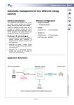
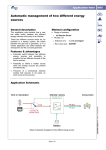
1
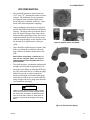
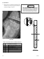
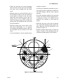
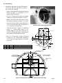
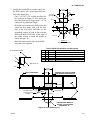
Cleaver-Brooks
.
$25.00 U.S
CLEAVER-BROOKS
IFGR Retro-Fit
250 - 800hp.
Installation Instructions
Induced Flue Gas Recirculation
Manual Part No. 750-181
2/98
i
Cleaver-Brooks
SAFETY PRECAUTIONS AND
ABBREVIATIONS
Abbreviations
Following is an explanation of the abbreviations,
acronyms, and symbols used in this manual.
Safety Precautions
It is essential to read and understand the following
safety precautions before attempting to operate the
equipment. Failure to follow these precautions may
result in damage to equipment, serious personal injury,
or death. A complete understanding of this manual and
the respective boiler Operation and Maintenance
manual is required before attempting to start-up,
operate or maintain the equipment. The equipment
should be operated only by personnel who have a
working knowledge and understanding of the
equipment. When setting up or operating the burner, be
sure to reference the applicable flame safeguard control
manual.
The following symbols are used throughout this manual:
! WARNING
DANGER
This symbol indicates a potentially
hazardous situation which, if not avoided,
could result in serious personal injury, or
death.
! CAUTION
DANGER
This symbol indicates a potentially hazardous situation which, if not avoided, could result in damage to the equipment.
NOTICE
This symbol indicates information that is vital
to the operation of this equipment.
ii
AC
Alternating Current
AR
Automatic Reset
ASME
American Society of Mechanical Engineers
ASTM
American Society of Testing and Materials
BHP
Boiler Horsepower
BTU
British Thermal Unit
°C
Degrees Celsius
CFH
Cubic Feet per Hour
Cu Ft
Cubic Feet
DC
Direct Current
°F
Degrees Fahrenheit
FM
Factory Mutual
FS
Flame Safeguard
ft
Feet
GPM
Gallons per Minute
Hd
Head
HT
Height
HTB
High Turndown Burner
HZ
Hertz
In H2O
Inches of Water
IRI
Industrial Risk Insurance
Lb
Pound
LE
Low Emission
LWCO
Low-Water Cut-Off
MM
Million
MFD
Micro-Farad
MR
Manual Reset
NEC
National Electric Code
No.
Number
pH
Measure of the degree of acid or base of a solution
P/N
Part Number
PPM
Parts Per Million
PR
Program Relay
psi
Pounds Per Square Inch
SAE
Society of Automotive Engineers
scfh
Standard Cubic Feet per Hour
T
Temperature
TC
Temperature Control
TI
Temperature Gauge
UL
Underwriter’s Laboratories
V
Volt
WC
Water Column
WSI
Watts Per Square Inch
Cleaver-Brooks
CLEAVER-BROOKS
IFGR Retro-Fit
250 - 800 hp Installation
Instructions
Induced Flue Gas Recirculation
© Cleaver-Brooks 1997, 1998
Please direct purchase orders for replacement manuals to your local
Cleaver-Brooks authorized representative.
Manual Part No. 750-181
2/98
Printed in U.S.A.
iii
Cleaver-Brooks
! WARNING
DANGER
DO NOT OPERATE, SERVICE, OR REPAIR THIS EQUIPMENT UNLESS YOU FULLY UNDERSTAND ALL
APPLICABLE SECTIONS OF THE APPROPRIATE OPERATION AND MAINTENANCE MANUAL.
DO NOT ALLOW OTHERS TO OPERATE, SERVICE, OR REPAIR THIS EQUIPMENT UNLESS THEY FULLY
UNDERSTAND ALL APPLICABLE SECTIONS OF the appropriate Operation and Maintenance MANUAL.
FAILURE TO FOLLOW ALL APPLICABLE WARNINGS AND INSTRUCTIONS MAY RESULT IN SEVERE
PERONAL INJURY OR DEATH.
TO: Owners, Operators and/or Maintenance Personnel
This installation manual presents information that will help to properly setup and care for the equipment. Study its contents
carefully. The unit will provide good service and continued operation if proper operating and maintenance instructions are followed. No attempt should be made to operate the unit until the principles of operation and all of the components are thoroughly
understood. Failure to follow all applicable instructions and warnings may result in severe personal injury or death.
It is the responsibility of the owner to train and advise not only his or her personnel, but the contractors' personnel who are servicing, repairing or operating the equipment, in all safety aspects.
Cleaver-Brooks equipment is designed and engineered to give long life and excellent service on the job. The electrical and mechanical devices supplied as part of the unit were chosen because of their known ability to perform; however, proper operating
techniques and maintenance procedures must be followed at all times. Although these components afford a high degree of protection and safety, operation of equipment is not to be considered free from all dangers and hazards inherent in handling and
firing of fuel.
Any "automatic" features included in the design do not relieve the attendant of any responsibility. Such features merely free him
of certain repetitive chores and give him more time to devote to the proper upkeep of equipment.
Because of state, local, or other applicable codes, there are a variety of electric controls and safety devices which vary considerably from one boiler to another.
Operating controls will normally function for long periods of time and we have found that some operators become lax in their
daily or monthly testing, assuming that normal operation will continue indefinitely. Malfunctions of controls lead to uneconomical operation and damage and, in most cases, these conditions can be traced directly to carelessness and deficiencies in testing
and maintenance.
The operation of this equipment by the owner and his operating personnel must comply with all requirements or regulations of
his insurance company and/or other authority having jurisdiction. In the event of any conflict or inconsistency between such
requirements and the warnings or instructions contained herein, please contact Cleaver-Brooks before proceeding.
iv
i
Cleaver-Brooks
Table Of Contents 78” IFGR
General Information ................................................................................................................................ 1-1
78" Model CB ........................................................................................................................................ 1-2
Boiler applications: .................................................................................................................................. 1-2
Utilities..................................................................................................................................................... 1-3
Components Supplied. ............................................................................................................................. 1-3
Other Items included in the IFGR Kit...................................................................................................... 1-4
Options ..................................................................................................................................................... 1-4
Major Installation Field Tasks. ................................................................................................................ 1-5
Required Order Information. ................................................................................................................... 1-5
List of Figures
78” CB Boiler with IFGR Retrofit.......................................................................................................... 1-1
Spudded Burnet Housing......................................................................................................................... 1-2
High Turndown Oil Gun and 3/4” Jackshaft With Dual Fuel Change Over and Proximity Switch. ..... 1-2
Additional Electrical Components May Be Required ............................................................................. 1-2
Impeller, Motor and Starter ...................................................................................................................... 1-3
Flue Gas Duct Piping ............................................................................................................................... 1-3
Asperator Piping ...................................................................................................................................... 1-4
Combustion Air Intake Hood................................................................................................. .................. 1-4
Insulation, insulation Retainers and Gasket Kit........................................................................................ 1-4
Spud Kit and High Turndown Oil Gun for Combination Firing .............................................................. 1-4
Optional Items; Burnet Housing,High Turndown Burner and Diffuser and Fan Motor ......................... 1-4
Retrofit-Induced FGR-78" Dia. ............................................................................................................... 1-6
Retrofit-Induced FGR-78" Dia. ............................................................................................................... 1-7
Insulation, Front Head 78" LE................................................................................................................. 1-8
Insulation, Front Head 78" LE ................................................................................................................. 1-9
Impeller 78” ........................................................................................................................................... 1-10
Rework, Air Inlet Assy. ......................................................................................................................... 1-11
Spud Kit & Pattern 78" LE, 30 ppm ...................................................................................................... 1-12
v
Cleaver-Brooks
Table Of Contents 96” IFGR
General Information .........................................2-1
Boiler Preparations: .........................................2-2
Site Preparations: .............................................2-3
Components Supplied ......................................2-4
Major Installation Field Tasks. ........................2-6
List of Figures
Fan Motor Mounted on the Front Head........... 2-1
IFGR Linkage Requires Manual Change for Dual
Fuel Units 3/4” Jackshaft..................................2-2
Linkage and Proximity Switch for Manual Change
Over Linkage. .................................................. 2-2
Spudded Burner Housing................................. 2-2
High Turndown Oil Gun and 3/4” Jackshaft ....2-2
High Turndown Nozzle Parts........................... 2-3
Larger Motors May Be Required .....................2-3
Additional Electrical Components Required ...2-3
Locations of Components. ............................... 2-4
Motor Starter and Insulation Kit.......................2-4
Impeller Assembly .......................................... 2-5
Optional Items ..................................................2-6
Required Modifications To the Front Head When
Using a Motor With a Larger Frame Size. .......2-7
Insulation and Wire Mesh Installed Inside Front Head.
2-8
View Inside the Front Head..............................2-9
Cut a Hole in the Inner Door.............................2-9
Rework of the Inner Door.............................. 2-10
Inner Baffle Layout. .......................................2-11
IFGR Valve in Wind Box. .............................2-12
Hole Location Wind Box................................2-12
SlotIFGRActuatingRodParallelwiththeValveDamper.
2-12
Install Insulation and Retainer ........................2-12
Rework Required to the Existing Wind Box for the
IFGR Valve Installation. ................................2-13
Dual Position Linkage.....................................2-14
Manual Linkage Change-Over........................2-14
Linkage Inside Front Head..............................2-14
Linkage Assembly IFGR SINGLE FUEL. ....2-15
Linkage Assembly IFGR DUAL FUEL .........2-16
Linkage Assembly IFGR DUAL FUEL .........2-17
Spuds, Burner Housing and Gaskets in Place. 2-18
Spud Pattern CB 500 hp (#090 1623)............ 2-19
Spud Pattern CB 600 hp (# 090 1624). ..........2-19
Spud Pattern CB 700 & 800 hp (# 090 1626). 2-20
Spud Pattern CB 400 hp (# 090 1627). ..........2-20
Damper Control Stop Screw Setting. .............2-21
Damper Control Shaft Settings...................... 2-22
Damper Settings. ............................................2-22
Jackshaft Arm Settings. .................................2-22
Adjusting Linkage and Setting Combustion. .2-23
Combustion Tester......................................... 2-23
List of Tables
ImpellerRetainerPartNumbersandSizeRequirements.
2-5
Front Head Insulation and Retainer Hardware. 2-8
Baffle Part Numbers and Description........... 2-11
Parts List for IFGR Valve Installation. .........2-13
Linkage Assembly Part Numbers
SINGLE FUEL. ............................................2-15
vi
Linkage Assembly Part Numbers
DUAL FUEL. ...............................................2-17
Gas Spud Part Numbers.................................2-18
Initial Settings for Setup of the IFGR System of
Standard CB Boilers 400-800 hp. .................2-21
Installation Instructions
IFGR RETROFIT
General Information
This manual identifies the installation of the
Induced Flue Gas Recirculation (IFGR) systems
for retrofit applications. These systems are used on
78" Model CB firetube dryback boilers (250 350hp). They are designed to provide a NOx
performance of under 30 ppm (3% O2, dry basis)
when firing natural gas.
blanket insulation firmly held in place with
wire mesh, retainers and rigidizer. Loose
insulation could cause blockage of the
burner air flow. Failure to follow these
instructions could cause serious personal
injury or death.
The equipment is designed to be installed in the
field on existing boilers. In addition to the items
and procedures listed, good judgment should be
used to identify and address any conditions that
may prevent the unit from working properly or
meeting the application requirements. All
operating parameters such as combustion air
r e q u i r e m e n t s , fuel p r o p e r t i e s , a l t i t u d e
compensation, operating controls should be
reviewed for their related application and
performance requirements.
For customer convenience, it is recommended that
the installation of the IFGR retrofit kit be scheduled
to coincide with annual maintenance. Be prepared
with the appropriate service tools, replacement
gaskets and maintenance items to perform any and
all service and maintenance required.
! WARNING
DANGER
IFGR Retro fit is only to be installed when
Cleaver-Brooks manufactured inner doors
and rear heads are used. Any rebuilt or
modified inner door or rear head installed
by a third party should be replaced or rebuilt
by an a u t h o r i z e d C l e a v e r B r o o k s
Representative. The inner door and rear
head must have either rigid insulation or
750-181
Figure 1: 78” CB Boiler with IFGR Retrofit
1-1
78” IFGR RETROFIT
BOILER PREPARATIONS:
Note: the boiler should be in good
condition,
with
no
ma jo r
modifications to the original design.
Components that are worn or in poor
condition should be replaced or
repaired.
•
This conversion is designed for burners firing
natural gas, light oil (ASTM #1 or #2 oil) or a
combination burner firing light oil or gas.
Application of other gaseous fuels must be
approved by Cleaver-Brooks.
Figure 3: High Turndown Oil Gun.
Note: This conversion must not be capable
of burning heavy oils.
•
A gas fired burner must be equipped with
spuds. If the existing housing will be modified
to add spuds, it must be in good mechanical
condition with no corrosion or cracking.
•
If spuds are being added to the gas burner, the
required gas pressure will probably increase.
The gas pressure regulator should be capable
of providing the increased pressure, or steps
should be taken to obtain higher spring rates or
a different regulator. Also, the gas pressure
switches may require a higher setting or a different switch range.
•
Figure 4: Additional Electrical Components May Be
Required
Oil fired units must use the High Turndown oil
gun (standard equipment for light oil from
about 1989).
Figure 2: Spudded Burner Housing
1-2
750-181
78” IFGR RETROFIT
SITE PREPARATION:
•
The stack draft (pressure) must be between
-0.25” and +.25” (measured in inches of water
column). The draft must also be consistent,
providing the same amount of draft at any
given firing rate, repeatable within 0.1" (measured at the stack temperature coupling).
•
Larger combustion air motors are required to
provide the IFGR and maintain the rated boiler
capacity. The larger motor provided in this kit
may also require changes to the fuses, motor
starter and interconnecting wiring. The service
connection should also be reviewed to insure
sufficient current supply. A new impeller, sized
for the total flow requirements, is also provided.
•
Figure 5: Impeller, Motor and Starter
There should be sufficient space in front of the
boiler to perform the work and to allow the
larger motor to fit without obstruction of the
aisle.
Note: Before scheduling a retrofit job, be
sure all the required parts and correct
components have been supplied and are in
good condition.
•
The stack must have a minimum unobstructed
straight vertical length of approximately 30"
above the boiler flange to attach the IFGR piping. The stack must also be of sufficient gauge
material to provide a welded connection.
Stacks with multiple walls and/or thin gauge
material may need to have a section replaced,
using a single wall heavy gauge steel material
(see installation drawings).
! CAUTION
DANGER
Chains or other devices used to attach a lifting
device to the fan/motor must be arranged so the
fan motor does not rotate or tilt when removed
from the front head. Failure to follow these instructions could result in damage to the equipment.
Figure 6: Flue Gas Duct Piping
750-181
1-3
78” IFGR RETROFIT
Components Supplied.
Figure 7: Aspirator Piping
•
New combustion air fan (impeller) and mounting hardware (see Figure 5).
•
New combustion air motor, and motor starter
(see Figure 5).
•
IFGR piping for flue gas duct assembly (see
Figure 6).
•
Aspirate line components (see Figure 7).
•
Modified air inlet assembly, to accept the
IFGR duct (see Figure 8).
•
Front head insulation and mounting components (see Figure 9).
A.Front door insulation, glue, wire mesh and
retaining clips.
B.Gaskets for the front door.
Figure 8: Combustion Air Intake Hood
•
Gas burner spuds for fuel series 200 and 700
(see Figure 10).
•
Oil burner nozzle for fuel series 100 and 200
(see Figure 10).
Other Items included in the IFGR Kit
•
Diffuser.
•
Nameplate
•
Wiring Diagram.
•
Operating and Maintenance Manual.
Figure 9: Insulation, insulation Retainers and
Gasket Kit.
Figure 10: Spud Kit and High Turndown Oil Gun for
Combination Firing
1-4
750-181
78” IFGR RETROFIT
Figure 11: Optional Items;
Burner Housing, High
Turndown Burner and
Diffuser and Fan Motor
Options
•
Replacement gas burner housing.
•
High turndown burner.
•
The normal variations in motor options (high
efficiency, TEFC, etc.) are available.
Major Installation Field
Tasks.
! WARNING
DANGER
Disconnect and lock out the main power to
the boiler and the fuel supply to the burner
before the front head is opened. Electrical
power and fuel supply must remain shut off
at all times when the front head is open.
Failure to follow this warning could result in
serious personal Injury or death.
! WARNING
DANGER
Be certain that the davit arm is under
tension before opening. Failure to follow
these instructions can result in serious
personal injury or death.
750-181
1. Remove the old fan and motor (see Figure 5).
The motors can weigh several hundred pounds,
and may require special rigging.
2. If the unit has oil firing, the air compressor will
need to be installed on the new motor as it was
with the original motor. In some cases, the tubing or piping may need to be altered to compensate for a different motor length.
3. The next step is to insulate the front door. The
insulation covers the lower portion of the door,
as shown in Figures 14 and 15.
a). Check the front door for unused
openings. These must be closed off to
prevent flue gas from escaping into the
boiler room.
b).Retainer strips are used to hold the edge
of the insulation in place at the fan outlet,
due to the high air velocities. Mark the
strip locations on the door for proper fitup (item 5 & 6 on Figure 14). The
retainers strips will be welded in place
after the insulation and wire mesh have
been installed.
c).Weld the retainer pins to the door,
maintaining 4” to 6” spacing. The retainer
pins should be placed wherever the
insulation will be.
d).Cut the insulation to fit the required
spaces, and glue it in place.
e).Cut away the insulation for the air
proving switch, rear door cooling line and
any other required opening.
f).Cover the insulation with the wire
mesh, and cut to fit the required spaces.
The mesh should have a minimum of 6” of
overlap.
g).Install the pin clips on the pins, and
bend the pins flat against the wire mesh.
h).Weld the retainer strips in place as
shown on Figures 14 and 15. The
insulation and wire mesh must be held
firmly by the retainers
1-5
78” IFGR RETROFIT
! WARNING
DANGER
The insulation must be firmly attached to
the door using high temperature glue, wire
mesh, retainer studs and clips, to insure
that the high air velocities will not allow the
insulation to come loose and plug the
burner air flow. Failure to properly attach the
insulation can result in serious personal
injury or death
4. Install the new fan and motor assembly. The
fan and motor will be larger than the existing
fan and motor to accommodate the IFGR flow.
If the boiler is oil fired, install the air compressor to the base and pipe and wire accordingly.
Refer to the Firetube Manual 750-91 for installation information. The motors can weigh several hundred pounds, and may require special
rigging. Adjust the gap between the impeller
and the housing for clearance of 0.045” to
0.060”. Check this clearance at several locations.
5. Remove the existing air inlet assembly (item 1,
Figure 13) and install the new air inlet assembly provided with the kit. If this is an oil fired
boiler, there will be an oil cooling coil that
must be installed in the new air inlet.
6. Install the IFGR piping (item 2, Figure 13).
Cut a hole in the stack at the position shown,
and install and weld the components as shown
in Figure 13. The piping is designed to provide
a fair amount of flexibility for positioning both
vertically and horizontally by use of the slip
collars in the piping assemblies.
7. Install the aspirator line as shown in Figures 12
and 13. Cut a hole in the top of the front door
and weld the coupling as shown.
Burner Setup
The burner setup and adjustments are described in
the boiler Operation and Maintenance Manual 75091
The NOx level should be adjusted to approximately
25 ppm throughout the firing range. There are two
adjustments that can be used to obtain the desired
NOx levels. First, at high fire, the IFGR rate can be
reduced (to increase the NOx level) by installing an
orifice plate between the flange in the IFGR piping.
The orifice plate has a smaller opening than the
IFGR piping assembly therefore reducing the
IFGR flow. After the required NOx levels are
obtained at high fire, the low fire NOx levels can be
adjusted with the manually operated valve on the
aspirator line. Opening the valve will increase the
IFGR flow and decrease the NOx level.
Notes
1-6
750-181
78” IFGR RETROFIT
BILL OF MATERIAL
ITEM REQ'D PART NO.
1
1
530-C-472
2
1
507-C-7527
3
1
880-A-617
4
1
880-A-615
5
1
858-56
6
1
465-C-1680
(SEE NOTE 5)
DESCRIPTION
AIR INLET ASS'Y, MODIFIED FOR INDUCED FGR
PIPING ASSEMBLIES, INDUCED FGR (3 SECTIONS)
HARDWARE KIT-INDUCED FGR PIPING W/ ORIFICE PLATES
PIPING KIT- ASPIRATION PIPING W/ GATE VALVE
COUPLING, FULL, 2" FORGED STEEL
INSULATION, FRONT HEAD INTERIOR, 78" DIA.
EXISTING STACK
3-1/16" DIA. HOLE
FOR ITEM #5
6-3/4" DIA. HOLE THRU
EXISTING STACK. LOCATE
AND CUTOUT TO SUIT
AT ASSEMBLY.
4"
1/8" SEAL
4
10-1/2"
2
REF. GATE
VALVE
3
17-1/2"
REF.
1
EXISTING CB. 78"
DIA. BOILER
5
12" REF.
1"
1
FRONT VIEW
Figure 12: Retrofit-Induced FGR-78” Dia.
750-181
1-7
78” IFGR RETROFIT
3-1/16" DIA. HOLE
FOR ITEM #5
5
4"
SEAL
1/8"
10-1/2"
4
8-1/2"
1
SEAL
1/4"
2
SEAL2 PLACES
1/8"
TYP.
3
REF. ORIFICE
SEAL 1/8"
1
6
SIDE VIEW
Figure 13: Retrofit-Induced FGR-78” Dia.
1-8
750-181
78” IFGR RETROFIT
3/4"-4"
1/8"
5
Figure 14: Insulation, Front Head 78" LE
SECTION VIEW OF FIGURE 15
750-181
1-9
78” IFGR RETROFIT
30 PPM
465-1680
ITEM
REQ.
1
57 SQ FT
2
150
3
150
128 OZ
4
5
2
6
2
57 SQ FT
7
78" GENERAL BILL OF MATERIAL
PART NO.
872-688
903-297
828-39
872-512
971-355
971-355
930-57
DESCRIPTION
BULK INSULATION, INSULWOOL, 1/4" THK,
PIN, WELDING, #10 GA. X 2-1/2" LG. ST. STL.
CLIP, WELDING ST. STL
ADHESIVE, SCOTCHGRIP #42NF
STRIP, 14 GA. x 1-1/2" x 32-1/2" LG.
STRIP, 14 GA. x 1-1/2" x 9-1/2" LG.
SCREEN 1/2" 19 GA. GALV.
"A"
5
TYP
45°
TYP.
2
3/4"-4
3
1/8"
1
4
7
6
VIEW OF INSIDE HEAD
Figure 15: Insulation, Front Head 78" LE
"A"
(SEE FIGURE 14)
1-10
750-181
78” IFGR RETROFIT
14
13
12
11
6
7
1
2
4
8
3
9
10
5
18 19
BLOWER MOTOR
SEE NOTE 1
1/32"
15
16 17
TABLE ITEMS 2 3 4 & 5
50-60 HZ.
ITEM
QTY
PART NO.
DESCRIPTION
CB 300
CB 250
CB 350
1
1
IMPELLER
GAS
OIL/COMB.
2
1
SPACER, IMPELLER
77-A-101
77-A-101
77-A-102
77-A-102
3
4
1
1
WASHER
NUT, SELF LOCKING, JAM
952-289
869-119
952-289
869-119
952-225
869-177
952-225
869-177
5
-
WASHER, SPACER
91-60
91-60
91-79
91-79
6
1
85-D-263
SUPPORT, MOTOR
7
1
22-B-237
PLATE, DIFFUSER
8
1
19-A-375
COVER, SHAFT
9
2
860-201
SCREW, MACH., RD. HD.
#10-24 X 3/8" LG.
10
2
952-117
LOCKWASHER, #10
11
1
32-A-919
GASKET, AIR HOOD
12
8
868-175
CAPSCREW, HEX. HD.
12"-12 X 1-3/4" LG.
13
10
952-94
LOCKWASHER, 1/2"
14
15
9
8
869-15
77-A-103
NUT, HEX. 1/2"-13
SPACER
16
15
952-93
LOCKWASHER, 3/8"
17
11
869-30
NUT, HEX. 3/8"-16
18
-
WASHER, SPACER .005
91-59
91-59
91-78
91-78
19
-
WASHER, SPACER 1/16"
91-61
91-61
91-80
91-80
TABLE ITEMS 18 & 19
50-60 HZ.
CB 300
CB 250
GAS
CB 350
OIL/COMB.
NOTE: 1. USE ITEMS 5 , 18 , & 19 AS REQUIRED
TO OBTAIN CLEARANCE OF 1/32".
Figure 16: Impeller 78”
750-181
1-11
78” IFGR RETROFIT
180
168
152
144
136
128
120
160
192
176 184
200
208
216
224
232
240
248
112
104
256
3
96
90
FIGURE 17: SPUD ARRANGEMENT
FOR 300 AND 350 HP
4
264
2
272
280
270
88
80
72
288
64
296
56
48
40
304
312
320
32
24
336
16
16
328
NO HOLE ON BOTTOM
0
CENTERLINE
NOTES!
1. SPUD PATTERN SHOWN IS AS VIEWED FROM
FRONT OF BOILER, THROUGH THE HOUSING.
2. APPLY NEVER SEEZ COMPOUND, ITEM 1 ,
TO SPUDS AND PLUGS BEFORE INSTALLING.
180
168
160
192
176
184
152
144
136
128
120
112
200
208
216
224
232
240
248
104
96
90
256
264
4
3
270
88
80
272
2
280
72
288
64
296
304
312
320
56
48
FIGURE 18: SPUD ARRANGEMENT
FOR 250 HP
40
32
336 328
24
16
16
0
1-12
NO HOLE ON BOTTOM
CENTERLINE
750-181
INSTALLATION INSTRUCTIONS
IFGR Retrofit
GENERAL INFORMATION:
This manual identifies the installation instructions
for the Induced Flue Gas Recirculation (IFGR)
systems used on retrofit applications. These
systems are used on Model CB firetube dryback
boilers (400-800 hp) produced after approximately
1970. They are designed to provide a NOx
performance of under 30 ppm (3% O2, dry basis)
when firing natural gas.
The equipment is designed to be installed in the
field on existing boilers. In addition to the items
and procedures listed, good judgment should be
used to identify and address any conditions that
may prevent the unit from working properly or
meeting the application requirements. All
operating parameters such as combustion air and
stack draft requirements, fuel properties, altitude
compensation, operating controls should be
reviewed for their related application and
performance requirements.
understanding of the boiler to be retrofitted, and the
appropriate Operation Service and Parts manual.
! WARNING
DANGER
IFGR Retro fit is only to be installed when
Cleaver-Brooks manufactured inner doors
and rear heads are used. Any rebuilt or
modified inner door or rear head installed
by a third party should be replaced or rebuilt
by an a u t h o r i z e d C l e a v e r B r o o k s
Representative. The inner door and rear
head must have either rigid insulation or
blanket insulation firmly held in place with
wire mesh, retainers and rigidizer. Loose
insulation could cause blockage of the
burner air flow. Failure to follow these
instructions could cause serious personal
injury or death.
For customer convenience, it is recommended that
the installation of the IFGR retrofit kit be scheduled
to coincide with annual maintenance. Be prepared
with the appropriate service tools, replacement
gaskets and maintenance items to perform all
service and maintenance required during the IFGR
installation.
The installation of this equipment and boiler
startup must be performed by a qualified service
person who has a complete understanding of the
installation procedures contained in this manual,
access to calibrated emission test equipment, an
750-181
Figure 1: Impeller Motor Mounted on the Front Head
with Internal Impeller.
2-1
96” IFGR Retrofit
BOILER PREPARATIONS:
Note: The boiler should be in good
condition, with no major modifications to
the original design. Components that are
worn or in poor condition should be
replaced or repaired.
• The IFGR conversion is designed for burners
firing natural gas, light oil (ASTM #1 or #2
oil) or a combination burner firing light oil
or gas. Application of other gaseous fuels
must be approved by Cleaver-Brooks. The
IFGR conversion should not be made to a
burner that will burn heavy oils.
• If spuds are being added to the gas burner,
the required gas pressure will probably
increase. The gas pressure regulator should
be capable of providing the increased pressure, or steps should be taken to obtain
higher spring rates or a different regulator.
Also, the gas pressure switches may require
a higher setting or a different switch range.
• Oil fired units must use the High Turndown
oil gun (standard equipment for light oil
from about 1989).
Figure 4: Spudded Burner Housing
Figure 2: IFGR Linkage Requires Manual ChangeOver for Dual Fuel Units and a 3/4” Jackshaft.
• The burner must have a 3/4” jack shaft. A
conversion is available if required.
Figure 5: High Turndown Oil Gun and 3/4” Jackshaft
Figure 3: Linkage and Proximity Switch for Manual
Change-Over Linkage
• A gas fired burner must be equipped with
spuds. If the existing housing will be modified to add spuds, it must be in good
mechanical condition with no corrosion or
cracking.
2-2
750-181
96” IFGR Retrofit
Figure 6: High Turndown Nozzle Parts.
Figure 7: Larger Motors May Be Required
SITE PREPARATIONS:
• The stack draft at the boiler outlet must be
between -0.25” and +0.25” water column.
The draft must also be consistent, providing
the same draft at any given firing rate,
repeatable within 0.1" water column.
• Larger combustion air motors are required to
provide for both IFGR and combustion air
delivery in order to maintain the rated boiler
capacity. The larger motor provided in the
IFGR kit may also require changes to the
fuses, motor starter and interconnecting wiring. The service connection should also be
reviewed to insure sufficient current supply.
A new impeller, sized for the total flow
requirements, is also provided.
• There should be sufficient space in front of
the boiler to perform the work and to allow
the larger motor to fit without obstruction of
the aisle.
Note: Before scheduling a retrofit job, be
sure all the required parts and correct
components have been supplied and are in
good condition.
750-181
Figure 8: Additional Electrical Components May be
Required
! CAUTION
DANGER
Chains or other devices used to attach a lifting
device to the fan/motor must be arranged so the
fan motor does not rotate or tilt when removed
from the front head. Failure to follow these instructions could result in damage to the equipment.
2-3
96” IFGR Retrofit
COMPONENTS SUPPLIED:
• New combustion air fan (impeller) and
mounting hardware.
• New combustion air motor and mounting
hardware (if required).
• IFGR duct and related hardware.
Front Head
Insulation
Combustion
Air Fan
IFGR
Duct
• Linkage to connect the jackshaft to the IFGR
duct.
Front
Baffle
• 3/4” jackshaft with extended length for the
IFGR linkage connection.
• Components to rework the front baffle.
• Gas burner spuds (for fuel series 200 and
700) if not on the existing burner.
• Combustion air motor starter.
• Front head insulation, glue, wire mesh and
retaining clips.
Combustion
Air Fan
Motor
IFGR
Control
Linkage
IFGR
Control
Linkage
Gas
Burner
Spuds
• Gaskets for the front head.
• Nameplate.
• Wiring Diagram.
• Installation instructions.
OPTIONS
Figure 9: Location of
Components
• Boiler derating, where larger motors may not
be required, and some burner components
are changed to allow the boiler to operate at
a lower capacity.
• The IFGR conversion may be combined with
the High Turndown Burner conversion,
which will add the capability for increased
turndown of both the gas and oil firing capabilities of the boiler.
• Several other conversion options (Flame
Safeguard, adding a fuel, updating fuel
trains to meet current insurance regulations,
etc.) could be included with the IFGR conversion, reducing overall cost of installation
and down tome.
Figure 10: Motor Starter, Insulation, Insulation
Retainers, and Gasket Kit.
2-4
750-181
96” IFGR Retrofit
1.641" (APPROX)
ADJUST TO ACQUIRE
THE SPECIFIED IMPELLER
TO IMPELLER HOUSING
GAP, DIM "C"
SPACER "A"
3-5/8"
REF.
NUT
WASHER
SPACER "B"
+0.010
0.050 -0.005
MOTOR
MOTOR SPACER
FAN LAYOUT 96" "CB"
USING NEW DESIGN
THREADED SHAFT
Figure 11: Impeller Assembly
Table 1: Impeller Retainer Part Numbers and Size Requirements.
MOTOR
SHAFT
IMPELLER
IMPELLER
HP
SIZE
SPACER "A"
SPACER "B"
NUT
WASHER
MOTOR
SPACER
1-3/8"
77-478 (1/4")
77-478 (1/4")
869-177
952-225
NOT REQ.
15 ODP
1-3/8"
77-478 (1/4")
77-478 (1/4")
869-177
952-225
NOT REQ.
15 TEFC
1-3/8"
77-432 (3/8")
77-436 (1/8")
869-177
952-225
77-465
20
1-3/8"
77-432 (3/8")
77-436 (1/8")
869-177
952-225
77-465
25
1-3/8"
77-463 (7/16")
77-476 (1/16")
869-177
952-225
77-465
30
1-3/8"
77-463 (7/16")
77-476 (1/16")
869-177
952-225
77-465
40 ODP
1-5/8"
77-462 (7/16")
77-477 (1/16")
869-180
952-338
77-465
40 TEFC
1-5/8"
77-462 (7/16")
77-477 (1/16")
869-180
952-338
77-466
50
1-5/8"
77-446 (5/8")
77-477 (1/16")
869-180
952-338
77-466
60
1-5/8"
77-462 (7/16")
77-477 (1/16")
869-180
952-338
77-466
75
1-5/8"
77-462 (7/16")
77-477 (1/16")
869-180
952-338
77-466
10
750-181
2-5
96” IFGR Retrofit
MAJOR FIELD
INSTALLATION TASKS.
The following outline covers the installation of
major IFGR components. This work must be
performed by qualified individuals who are trained
in the installation and setup of low emission
Cleaver-Brooks burners. In addition, other skills
are required to perform welding, wiring and other
tasks. It is the installers responsibility to insure that
properly trained individuals are performing the
work.
! WARNING
DANGER
Disconnect and lock out the main power to
the boiler and the fuel supply to the burner
before the front head is opened. Electrical
power and fuel supply must remain shut off
at all times when the front head is open.
Failure to follow this warning could result in
serious personal Injury or death.
! WARNING
DANGER
The inner door must be in good operational
and mechanical condition. If excessive
cracking or deterioration is evident,
replacement of the rear door is required to
prevent plugging of burner air flow. Failure
to follow this warning could result in serious
personal injury or death.
! WARNING
DANGER
Be certain that the davit arm is under
tension before opening. Failure to follow
these instructions can result in serious
personal injury or death.
1. Remove the old fan and motor, and install the
new fan and motor. Refer to the Firetube Manual 750-94 for information on fan and motor
removal. The motors can weigh several hundred pounds, and may require special rigging.
• Some specific motor size increases will
require a modification to the front door
opening and motor mounting stud location.
Specifically, this will happen when the
motor changes from a 286TD (or smaller
frame) to a 324TD or larger frame. The
details for this change are shown on Figure
13.
Note: The 286TD motor frame will be 40 hp
or smaller in an Open Drip Proof design, or
30 hp or smaller in a TEFC design for current
motor production. Older motor styles and
other motor requirements will have different
frame and hp relationships.
• See Figure 11 and Table 1 for the assembly
details showing the spacers, fan and nut
assembly to the motor shaft.
• The fan housing should be positioned to provide a gap of 0.045” to 0.06” between the
housing and the impeller. The clearance
should be checked at several locations
around the diameter and at the inside and
outside of the impeller diameter.
• If the new motor is 30 hp or larger, it will
require a motor support. The motor support
must be bolted to the motor base and
adjusted for proper alignment prior to welding the support to the front head.
Figure 12: Optional Items; Burner Housing, High
Turndown Burner and Diffuser.
2-6
2. Drill the three holes in the front head for
mounting the IFGR linkage over travel mechanism (see Figures 2 and 13). Cut 6” from the
end of the brace on the inside of the front head,
as shown on Figure 13 to provide space for the
IFGR linkage.
750-181
96” IFGR Retrofit
NOTE: THIS MODIFICATION IS REQUIRED ONLY
WHEN THE MOTOR FRAME SIZE INCREASES FROM
286TD OR SMALLER, TO 324TD OR LARGER.
#7 (.201) DRILL
TAP 1/4"-20UNC
(2) HOLES
20"
1-1/4"
1-1/4"
21/32" DRILL, TAP 3/4"-10 UNC
(4) HOLES, EQUALLY SPACED ON A
16" DIA. B.C. FOR STUDS.
45°
"A"
14" (REF.)
5"
14-1/16" ±1/32"
DIA. HOLE
"A"
6"
STUDS TO BE
FLUSH WITH
INSIDE FACE
OF FRONT HD.
SECTION "A-A"
FRONT HEAD
CL
1-1/8" DIA. HOLE
CUT 6" OFF END OF
SUPPORT LOCATED INSIDE
OF FRONT HEAD TO CLEAR
OVERTRAVEL MECHANISM.
MOTOR SUPPORT REQUIRED
ONLY WHEN MOTOR SIZE
INCREASES TO 30HP OR LARGER
Figure 13: Required Modifications to the Front Head When Using a Motor With a Larger Frame Size
750-181
2-7
96” IFGR Retrofit
3. The next step is to insulate the front head. The
insulation covers the lower portion of the head,
as shown in Figures 14 and 15.
! WARNING
DANGER
The insulation must be completely and
firmly attached to the door, so that the high
air velocities will not allow it to come loose.
Failure to properly attach the insulation can
result in serious personal injury or death
3/4"-4"
1/8"
5
Figure 14: Insulation and Wire Mesh Installed Inside
Front Head.
Table 2: Front Head Insulation and Retainer Hardware.
96" GENERAL BILL OF MATERIAL
ITEM
1
2
3
4
5
6
7
8
9
2-8
PART NO.
872-688
903-297
828-39
872-512
971-355
971-355
N/A
N/A
930-57
DESCRIPTION
BULK INSULATION, INSULWOOL, 1/4" THK,
PIN, WELDING, #10 GA. X 2-1/2" LG. ST. STL.
CLIP, WELDING ST. STL.
ADHESIVE, 3M #42NF
STRIP, 14 GA. x 1-1/2" x 33" LG.
STRIP, 14 GA. x 1-1/2" x 9-1/2" LG.
N/A
N/A
SCREEN 1/2" 19 GA. GALV
SECTION "A-A"
750-181
96” IFGR Retrofit
• Check the front door for unused openings.
These must be closed to prevent recirculated
flue gases from escaping into the boiler
room.
and glue it in place.
• Cut away the insulation around the air proving switch, rear door sight glass cooling line,
the IFGR linkage, and any other required
opening.
• Retainer strips are used to hold the edge of
the insulation in place at the fan outlet, due
to the high air velocities at the fan outlet.
Mark the strip locations on the door for
proper fit-up of the insulation and wire
mesh. The retainer strips will be welded into
position after the insulation and wire mesh
has been installed.
• Cover the insulation with the wire mesh and
cut the wire mesh to fit the required spaces.
A minimum overlap of 6” should be used
whenever two sections of wire mesh are
joined.
• Install the pin clips on the pins to hold the
wire mesh and insulation tight against the
door. Bend the pins flat against the wire
mesh (see Figure 14).
• Weld the retainer pins to the inside of the
front head, maintaining 4” to 6” spacing.
The retainer pins should be placed wherever
the insulation will be secured to the front
head.
• Weld the retainer strips in place as shown on
Figures 14 and 15. The insulation and wire
mesh must be held firmly by the retainers.
• Cut the insulation to fit the required places
"A"
5
45°
45°
2, 3
3/4"-4
1/8"
1,4
6
9
"A"
Figure 15: View Inside the Front Head.
750-181
2-9
96” IFGR Retrofit
4.
Modify the inner door for the IFGR control
valve fit-up and allow the baffle to go below
the control valve opening.
• Remove the insulation from the inner door as
shown on Figure 17, to provide a 14 1/4”
opening below the baffle.
• Cut an 11” diameter hole in the steel portion
of the door, as shown in Figures 16 and 17.
• Remove the flat bar from the inner door baffle location as shown on Figure 17 to make
room for the new baffle location. Remove a
6 3/8” section from the upper bar. Remove a
14” section from the lower bar.
Figure 16: Cut a Hole in the Inner Door.
• The flat bar (item 1, Figure 17) should be
bent to a 7” inside radius, with a 2 1/8”
straight length on each end. Weld the 14”
semi circle on the inner door completing the
lower portion of the baffle fit-up area.
14"
INSIDE
7"
5-1/2" I.R.
69
°
34-1/2
• The 6 11/16” bar (item 2, Figure 17) should
be bent to a 5 1/2” inside radius. Weld the 6
11/16” bar to the upper portion of the baffle
fit-up area.
2-1/8"
2
1
ITEM REQ. PART NO.
1
2
1
1
973-6
973-6
DESCRIPTION
SHEET, #10 GA. (.1345) X 2" X 26-7/16" LG. HRS
TYP.
1"
8
TYP.
7" I.R.
1"
8
SHEET, #10 GA. (.1345) X 2" X 6-11/16" LG. HRS
1-4
DETAIL "A"
CUTOUT IN LOWER
INSULATION
14-1/4"
7-1/8"
6-3/8"
11" DIA. HOLE
(IN STEEL PORTION
OF INNER DOOR)
CUTOUT IN UPPER
INSUL. RETAINER
3-3/16"
SEE DETAIL
2
"A"
BAFFLE FIT-UP
AREA
SEE DETAIL
1
"A"
14"
C
L
C
L
FRONT VIEW
2-10
Figure 17: Rework of the Inner Door. (Viewed from vessel side)
750-181
96” IFGR Retrofit
12-1/2"
INSIDE
5. Modify the front baffle to provide a space for
the IFGR control valve to pull gases from the
end of the fourth pass.
• Cut a 7 1/8” by 12 3/4” section out of the baffle, as shown on Figure 18. Also insure that
the center bolts are no longer than 1 1/4” by
cutting off any additional length.
1
6-1/4"
9/32" DIA.
(11) HOLES
1"
8
2
9/16"
• Weld the steel section to the baffle where the
cutout has been made. Seal weld the back
plate to the semi-circle and either cut the
protruding corners or bend in line with the
fabricated baffle. Drill holes in the edge of
the added section to retain the gasket as
shown in Figure 18.
7"
INSIDE
1
1"
1
3-1/2"
22-1/2
TYP.
6-1/4" I.R.
2
2
DETAIL "A"
• Install the gasket on the edge of the baffle,
using the rivets supplied.
IFGR DUCT ASSEMBLY
Table 3: Baffle Part Numbers and Description.
EXISTING BAFFLE (REF.)
ITEM REQ. PART NO.
1
2
3
4
5
5
3
1
1
1
1
33
973-6
973-6
853-394
971-291
841-551
DESCRIPTION
SHEET, #10 GA. (.1345) X 9-3/4" X 12-1/2" LG. HRS
SHEET, #10 GA. (.1345) X 7" X 26-7/8" LG. HRS
GASKET, 9/16" BULB X 2" X 111" LG.
STRIP, PERF. #16 GA. X 7/8" X 111" LG.
RIVET, SPLIT .225 DIA. X 3/4" LG.
SEE DETAIL "A"
5/8"
4
12-3/4"
CUTOUT
FRONT TUBE SHEET
6-3/8"
REMOVE THIS SECTION FROM
THE EXISTING FRONT BAFFLE
7-1/8" CUTOUT
CUT-OFF THESE
2 STUDS TO DIM.
SHOWN.
+0"
-1/16"
1-1/4"
SEE DETAIL "A"
1"
8
CL BAFFLE
NEW SECTION ADDED TO
BAFFLE CUTOUT AREA
SEE DETAIL "A"
Figure 18: Inner Baffle Layout.
750-181
2-11
96” IFGR Retrofit
6. Windbox modification for the IFGR control
valve and linkage
• Remove and discard the cover of the back of
the windbox.
• Drill three holes in the bottom of the windbox for the linkage and bearing block
mounting, as shown on Figure 20. Install the
bearing block, item 2 on Table 4 and figure
25.
• Install the IFGR control valve and cover
plate, as shown on Figures 19 and 23. The
valve shaft must pass through the bottom of
the windbox (bearing block). The valve shaft
Figure 21: Slot IFGR Actuating Rod Parallel with
the Valve Damper.
Figure 22: Install Insulation and Retainer.
Figure 19: IFGR Valve in Wind Box.
15/16"
3/4" DIA.
INSIDE
HOLE
7/8"
BOTTOM
CL
AIR DUCT
1-3/4"
1/2" DIA.
(2) HOLES
VIEW "A"-"A"
should be lubricated with high temperature
anti-seize compound at the bearing. It may
be helpful to cut a notch in the bottom of
the valve shaft to indicate valve location,
as shown on Figure 21. Install and adjust
the threaded rods to hold the valve in position against the impeller housing (see Figure 23). These rods will help to retain the
position of the components when the head
is closed.
• Install the insulation and retainer on the end
of the IFGR control valve, as shown on figures 22. These items will seal against the
Figure 20: Hole Location in the Bottom of the
Wind Box.
2-12
750-181
96” IFGR Retrofit
Table 4: Parts List for IFGR Valve Installation.
ITEM REQ.
PART NO.
1
2
3
4
1
1
1
1
SEE TABLE
306-C-79
19-C-1328
872-278
5
6
1
1
797-2374
32A2556
7
8
9
2
2
2
868-405
869-21
952-294
10
11
2
952-92
869-36
8
8
8
12
13
14
15
1
1
16
17
18
1
1
4
19
20
4
21
BEARING PLATE ASSEMBLY
COVER PLATE, AIR DUCT
INSULATION, BLANKET 1" X 18" O.D. (SEE NOTE)
ADHESIVE
GASKET, DAMPER IFGR
CAPSCREW, HEX. HD. 1/4"-20 X 7/8" LG.
NUT, HEX. 1/4"-20
WASHER, FLAT 1/4"
LOCKWASHER, 1/4"
NUT, HEX. 5/16"-18
WASHER, FLAT 5/16"
952-297
952-114
32A2327
32A2328
853-899
SEE TABLE
841-338
LOCKWASHER, 5/16"
GASKET, COVER PLATE
GASKET, SEAL 88-1/2" LG.
GASKET, AIR DUCT TO FRONT HD. 97" LG. (NOT SHOWN)
RETAINER, INSULATION
THREAD STOCK, 3/8"-16 X 4-3/8" LG. (SEE DETAIL)
NUT, HEX. 3/8"-16
LOCKWASHER, 3/8"
GASKET, BEARING PLATE
869-30
952-93
4
1
DESCRIPTION
DAMPER ASSEMBLY, IFGR
32A2555
1/16" WIDE X 3/32" DEEP
SLOT, THIS END ONLY
4-3/8"
1
4 5
14
17
+0"
-1/16"
DETAIL ITEM 18
INSTALL BEFORE CLOSING FRONT HEAD,
RETAINER IS TO FIT LOOSE OVER DAMPER
HOUSING WITH 1/4" DIA. BAR SIDE
TOWARD INSULATION, ITEM 4.
USE EXISTING COVER PLATE
MOUNTING SCREWS
3-5/8" TYP.
18
15
3
19
6 11 12 13
181920
20
AFTER INSTALLING AIR DUCT INTO FRONT HEAD,
ADJUST SCREWS, ITEM 18, EQUALLY AGAINST
IMPELLER HOUSING, AND LOCK IN PLACE WITH
NUT, ITEM 19.
15
3
27-1/2 °
REF.
14
6 11 12 13
4 5
1
2
3
1
21 2
750-181
17
7 8 9 10
"A"
"A"
Figure 23: Rework Required to the Existing Wind Box for the IFGR Valve Installation.
2-13
96” IFGR Retrofit
inner door, and insure that no insulation
breaks free and plugs the valve or burner
opening.
Figure 24: Dual Position Linkage
7. There are two linkage styles used for IFGR
systems, a single position drive used for single fuels (see Figure 27) and a dual position
drive used for dual fuels (see Figure 28).The
dual position drive allows for two different
FGR flow rates, matching the combustion
requirements for each fuel. (see Figure 24).
The linkages are the same except for the connections to the jackshaft.
• Install the over-travel mechanism on the
front head (item 1, Figure 27 and 28). Connect the linkage (items 3, 6 and 10) from
the over-travel mechanism on the door to
the IFGR damper rod, as shown on Figures
25, 26, 27 and Table 6.
• Install the 3/4” jackshaft assembly on the
front head, as shown on Figure 24 and 25.
• Install the linkage between the shaft assembly and the jackshaft.
• For a single fuel system, this is a link (item
2) and drive arm (item 7) as shown on figure 27.
Figure 25: Manual Linkage Change-Over
• For dual fuel systems, there are two drive
arms (items 5 and 16) on the jackshaft and
one link (item 2). A proximity sensor (item
18) is located of the jackshaft. Adjust the
position of the components as shown on
Figures 34, 36 and Table 6. Install the
“GAS OIL” nameplate on the front head as
shown on Figure 28.
• Set the linkage to the initial settings
described on Table 8 and Figures 34, 35,
and 36.
Note: Check the movement of the IFGR
l i n k a g e by r o t a t i n g the j a c k s h a f t
throughout its normal travel. The linkage
and valve should move smoothly without
jerky actions and without interference or
strained movement.
Figure 26: Linkage Inside Front Head
2-14
750-181
96” IFGR Retrofit
IFGR DAMPER ASS'Y.
(REF.)
SEE NOTE #1
3
FRONT HEAD
(REF.)
6
SEE NOTE #1
SEE NOTE #1
10
NOTE:
4
1
5
7
1.) REFER TO INITIAL IFGR SETTINGS
Table 8, page 21
PLAN VIEW
2
FRONT HEAD
(REF.)
9
1
8
1
IFGR DAMPER ASS'Y.
(REF.)
3
SEE NOTE #1
2
6
SEE NOTE #1
5
3
2
7
10
6 10
4
SEE NOTE #1
SIDE VIEW
8"
FRONT VIEW
9-3/8"
7
5
Figure 27: Linkage Assembly for IFGR Retrofit SINGLE FUEL
Table 5: Linkage Assembly Part Numbers and Description SINGLE FUEL
ITEM REQ.
750-181
PART NO.
1
2
3
4
5
1
1
1
1
1
427-C-251
67-A-796
476-C-223
974-42
2-A-331
6
1
287-A-50
7
8
9
2
2
2
860-39
868-136
952-92
10
2
860-101
DESCRIPTION
DAMPER CONTROL, SHAFT ASSEMBLY
LINKAGE ASSEMBLY, JACKSHAFT
LINKAGE ASSEMBLY, DAMPER
JACKSHAFT, 3/4" DIA. X 47-1/2" LG. (CHAM. BOTH ENDS)
DRIVE ARM, JACKSHAFT
DRIVE ARM, DAMPER
SETSCREW, SOCKET HD. 1/4"-20 X 3/8" LG.
CAPSCREW, HEX. HD. 1/4"-20 X 3/4" LG.
LOCKWASHER, 1/4"
SETSCREW, SOCKET HD. 1/4"-20 X 1/2" LG.
2-15
96” IFGR Retrofit
NOTES:
1. REFER TO TABLE 8, PAGE 21 FOR INITIAL IFGR SETTINGS.
2. ATTACH CONDUIT ADAPTER, ITEM 19, TO PROXIMITY
SWITCH, ITEM 18, AND RUN PROXIMITY SWITCH WIRES
THROUGH NON-METALLIC CONDUIT, ITEM 30.
IFGR DAMPER ASS'Y.
(REF.)
SEE NOTE #1
3
FRONT HEAD
6
(REF.)
SEE NOTE #1
10
SEE NOTE #1
PLAN VIEW
4
2
1
18
5
7
7
7
16
11
12 13
19
17
15
9
1
8
SEE NOTE #1
2
SEE NOTE 2
17
21
7
20
SEE NOTE #1
19
3/4"
NAMEPLATE
5
GAS
3
6
10
4
OIL
2"
7
18
3-1/2"
8-1/4"
7
16
11
12
13
15
FRONT VIEW
Figure 28: Linkage Assembly for IFGR Retrofit DUAL FUEL (1 of 2)
2-16
750-181
96” IFGR Retrofit
Table 6: Linkage Assembly Part Numbers and Description DUAL FUEL
ITEM REQ.
PART NO.
1
2
3
4
5
6
7
8
9
1
1
1
1
2
1
4
2
2
427-C-251
67-A-798
476-C-223
974-42
2-A-332
287-A-50
860-39
868-136
952-92
10
11
12
13
14
15
16
17
18
19
2
1
1
1
2
1
1
1
1
860-101
883-70
869-22
952-93
NOT USED
952-106
2-A-333
2-A-334
836-1032
848-1158
20
21
2
1
848-1159
848-1160
DESCRIPTION
DAMPER CONTROL, SHAFT ASSEMBLY
LINKAGE ASSEMBLY, JACKSHAFT
LINKAGE ASSEMBLY, DAMPER
JACKSHAFT, 3/4" DIA. X 47-1/2"" LG. (CHAM. BOTH ENDS)
DRIVE ARM, JACKSHAFT
DRIVE ARM, DAMPER
SETSCREW, SOCKET HD. 1/4"-20 X 3/8" LG.
CAPSCREW, HEX. HD. 1/4"-20 X 3/4" LG.
LOCKWASHER, 1/4"
SETSCREW, SOCKET HD. 1/4"-20 X 1/2" LG.
BALL SCREW, FOR TUTHILL NO. S-109 QUICK DISCONNECT
NUT, HEX. 3/8"-24 UNF
LOCKWASHER. 3/8"
NOT USED
WASHER, FLAT 3/8" SAE TYPE
DRIVE ARM, JACKSHAFT (OIL)
ARM, JACKSHAFT PROXIMITY SWITCH MOUNTING
PROXIMITY SWITCH
CONDUIT ADAPTER, 1/2" NPT X 30 MM
CONDUIT FITTING, 1/2" NPT STRAIGHT, NON-METALLIC
CONDUIT,1/2" FLEXIBLE, NON-METALLIC (CUT TO SUIT)
FRONT HEAD
(REF.)
1
2
3
IFGR DAMPER ASS'Y.
(REF.)
GAS ARM
10
6
SEE NOTE #1
5
7
OIL & SENSOR ARM
SIDE VIEW
SEE NOTE #1
16
7
17
7
Figure 28: Linkage Assembly for IFGR Retrofit DUAL FUEL (2 of 2)
750-181
2-17
96” IFGR Retrofit
Table 7: Gas Spud Description and Part Numbers
400 HP.
ASS'Y 090 1627
500 HP.
600 HP.
ASS'Y 090 1623 ASS'Y 090 1624
700 & 800 HP.
ASS'Y 090 1626
ITEM REQ. PART NO. REQ. PART NO. REQ. PART NO. REQ. PART NO.
1
1
1
887-27
887-27
887-27
887-27
1
1
57-1025
6
11
57-1025
2
57-1025
9
5
57-1025
57-1024
13
4
57-1024
3
57-1024
12
8
57-1024
16 57A1023
4
0
57A1023
24
57A1023
20
57A1023
8
5
9
858-1084
858-1084
858-1084
858-1084
5
8
0
0
57-1197
57-1197
57-1197
57-1197
6
14
3
NOTE: APPLY NEVER SEEZ COMPOUND, ITEM 1 , TO
SPUDS AND PLUGS BEFORE INSTALLING.
BASIC BILL OF MATERIAL
DESCRIPTION
ANTI SEIZE COMPOUND
GAS SPUD, 1/4 NPS 4-1/4 LG.
GAS SPUD, 1/4 NPS 2-1/4 LG.
GAS SPUD, 1/4 NPS 1-1/4 LG.
PLUG, PIPE 1/4 NPT BRASS
GAS SPUD, 1/4 NPS X 3-1/4" LG.
NOTE! SPUD PATTERN SHOWN IS AS VIEWED FROM
FRONT OF BOILER THROUGH THE HOUSING.
2 3 4 6
FROM TABLE 6
SECTION "A-A"
(SEE FIGURES , 29, 30, 31 & 32)
Figure 29: Spuds, Burner Housing and Gaskets in Place.
8. The burner requires certain components and
configurations to function as a low NOx
burner. For a gas burner, the diffuser and gas
spud arrangement is required. The diffuser is
provided with the IFGR kit. The gas spuds are
also included in the kit, and are to be installed
as shown on Table 7 and Figures 29-33. Antiseize compound is required on the gas spuds to
prevent the threads from seizing. A combination gas/oil burner will require a High Turndown style oil gun in addition to the above
items. If the boiler uses a straight oil burner,
the diffuser and oil gun must be installed to
allow the burner to function properly.
9. The motor size change will require changes to
the motor starter and fuses, which are included
in the kit. In addition, the wiring and supply
capacity should be reviewed to insure that they
2-18
meet the requirements for the new motor,
National Electric Code and any other codes
may apply to the installation.
! CAUTION
DANGER
The conduit connection to the proximity sensor
must be positioned to allow free movement of
the sensors during modulation. If the unit is
equipped with a proximity sensor, insure that
the cables are allowed free movement. Failure
to follow this caution could result in equipment
damage.
750-181
96” IFGR Retrofit
180
152160
144
136
128
Figure 30: Spud Pattern CB 500 h.p.
(#090 1623).
168 176184 192
120
200208
216
224
232
240
112
248
104
256
96
90
88
80
6
2
3
5
264
272
280
72
288
64
Note:
Spud patterns shown as
viewed from the front of
the boiler
296
56
304
312
320
328
336
48
40
32
24
NO HOLE ON BOTTOM
CENTERLINE
180
152
176 184 192
160 168
200
208
144
216
224
136
128
232
120
Figure 31: Spud Pattern CB
600 h.p. (# 090 1624).
240
112
248
104
256
96
90
270
4
88
3
2
264
272
270
5
80
280
288
72
64
296
56
304
48
312
40
320
328
32
24
336
NO HOLE ON BOTTOM
CENTERLINE
750-181
2-19
96” IFGR Retrofit
180
152
160 168
176184192
200
144
136
128
Figure 32: Spud Pattern CB
700 & 800 h.p. (# 090 1626).
208
216
224
232
120
240
112
248
104
256
96
90
4
88
6
80
72
Note:
Spud patterns shown as
viewed from the front of
the boiler
2
264
272
3
280
5
64
56
40
336
24
180
152
144
136
128
160 168
176184 192
200
120
NO HOLE ON BOTTOM
CENTERLINE
208
216
224
232
240
112
248
104
256
96
90
288
296
304
312
320
328
48
32
270
4
2
264
88
272
3
80
5
270
280
288
72
64
56
Figure 33: Spud Pattern CB
400 h.p. (# 090 1627).
296
304
48
312
320
328
40
32
24
336
NO HOLE ON BOTTOM
CENTERLINE
NOTE: HOLE @ 256 TO BE LEFT OPEN.
(NO PLUGS OR SPUDS)
2-20
750-181
96” IFGR Retrofit
Table 8: Initial Settings for Setup of the IFGR System of Standard CB Boilers 400-800 hp.
BOILER HP PPM NOX “A”
“B”
“C”
“D”
“E”
“F”
“G”
“H”
“I”
“J”
400
30
15°
1"
2-3/4"
#1
#4
20°
70°
#8
40°
20°
500
30
15°
1"
2-3/4"
#1
#4
20°
70°
#8
40°
20°
600
30
15°
1"
2-3/4"
#1
#4
20°
70°
#8
40°
20°
700
30
15°
1"
2-3/4"
#1
#4
20°
70°
#8
40°
20°
800
30
15°
1"
2-3/4"
#1
#4
20°
70°
#8
40°
20°
NOTE !
SETTINGS SHOWN ARE APPROXIMATE INITIAL SETTINGS ONLY,
ACTUAL FIELD SETTINGS WILL VARY FROM BOILER TO BOILER.
IMPORTANT !
AFTER CONNECTING THE DAMPER
LINKAGE, BUT BEFORE CONNECTING THE JACKSHAFT LINKAGE,
MANUALLY ROTATE THE DAMPER
CONTROL SHAFT UNTIL THE DAMPER
IS IN THE FULL OPEN POSITION. THEN
ADJUST THE SCREW TO TOUCH THE STOP
ARM AND LOCK IN PLACE WITH THE LOCK NUT.
AFTER SETTING THE CONTROL SHAFT
DRIVE ARMS AS SHOWN IN THE FRONT
VIEW, ADJUST THE SCREW TO TOUCH THE
STOP ARM AND LOCK IN PLACE
WITH THE LOCK NUT.
PLAN VIEW
Figure 34: Damper Control Stop Screw Setting.
750-181
2-21
96” IFGR Retrofit
"E" (LINKAGE
CONNECTION POINT)
5
"F"
4
3
2 1
1
2
3
4
5
6
7
8
"G"
"H" (LINKAGE
CONNECTION POINT)
FRONT VIEW
Figure 35: Damper Control Shaft
Settings.
"C"
1
2
"B"
"D" (LINKAGE
CONNECTION POINT)
COLLAR ASSEMBLY
"A"
PLAN VIEW
Figure 36: Damper Settings.
GAS ARM
"J"
OIL & SENSOR ARMS
"K"
SIDE VIEW
Figure 37: Jackshaft Arm Settings.
2-22
750-181
96” IFGR Retrofit
BURNER SETUP
The burner setup and adjustments are defined in the
CB-LE Firetube Operation and Maintenance
manual (750-94). Burner setup and adjustments
should only be performed by a combustion
technician trained in low emission Firetube burner
setup and adjustment
• NOx levels on natural gas will be less than 30
ppm (corrected to 3% Oxygen, dry basis)
throughout the operating range. There are no
NOx emission guarantees for oil firing.
• CO levels on gas firing will be less than 200
ppm (air free basis) throughout the operating
range.
Figure 38: Adjusting Linkage and Setting
Combustion.
• Smoke spots levels on oil firing will be less
than a #2 (Bacharach or ASTM).
• Turndown will be 4-to-1 on the standard
burner (both gas and oil). The optional high
turndown burner will provide 8-to-1 turndown on gas and 6-to-1 turndown on oil.
! WARNING
DANGER
Improper adjustment of air, fuel, or flue gas
r e c i r c u l a t i o n c o n t r o l s can p r o d u c e
dangerously low excess air levels in the
boiler furnace, which under extreme
c o n d i t i o n s may r e s u l t in u n s t a b l e
combustion. All adjustments must be made
by a qualified Cleaver-Brooks combustion
technician. Failure to follow this warning
could cause serious personal injury or
death.
750-181
Figure 39: Combustion Tester.
2-23
96” IFGR Retrofit
Notes
2-24
750-181
NOTES
Performance Proven Worldwide
e-mail: [email protected]
Web Address: http://www.cleaver-brooks.com