1
Worth Data
WDP Keyboard
Wedge Reader
Users Manual
For Model P11/12
For Models purchased prior to 8/00
Introduction
Worth Data' WDP Readers are versatile bar code readers that attach to the IBM
PC, XT and AT; all IBM PS/2 Models; any PC keyboard-compatible or buscompatible unit; and all Macintosh ADB models. The WDP provides bar code
input data to any host computer program exactly as if the data had been typed at
the keyboard, including function and control key support. WDP Reader features
include:
•
Bar codes
The WDP Reader automatically reads and discriminates between Code 39,
Full ASCII Code 39, Interleaved 2 of 5, Codabar, Code 128, EAN-13, EAN8, UPC-E, UPC-A (with or without supplements), MSI, LabelCode4,
LabelCode5, Code 93, and Plessey.
•
PC or Macintosh Interface
The WDP Reader is presently the only reader capable of internal or external
installation on PCs (External-only on Microchannel PS/2's and the
Macintosh.) For external mounting, its lightweight, unobtrusive case can be
attached to the side of the computer, monitor or desk with Velcro. For internal
mounting, the board is easily removed from the case and inserted into a PC's
ISA slot. If your MAC or PC has only a USB port for keyboard attachment,
the USB Wedge Saver bridges the WDP to a USB port.
•
Scanner options
The WDP Reader comes with a high quality USA-made stainless steel wand
scanner. Additional scanner options include moving-beam laser scanners,
CCD scanners, MagStripe scanners for reading credit card magnetic strips,
and bar code slot scanners for badges and other thin, flat surfaces.
•
Integrated Laser & Integrated CCD Wedge Reader
The Integrated Laser Readers and the Integrated CCD Readers are complete
WDP Readers with the decoder built into the scanner handle. Just plug the
unit in between your computer and keyboard and you're ready to go. They
work with any PC keyboard-compatible computer, all Macintosh ADB
models and USB computers (using the Wedge Saver).
•
Configuration is easy
The WDP Reader is easily configured for your system by scanning a bar coded
Setup Menu. There are no dip switches to set. On the separate decoder
models, opening of the reader's case is required only for internal bus
installation, Track 1&2 Magstripe, and for setting the decode light on a laser
or CCD Scanner. The PC/PS2 Y cable can be switched from 5 pin to 6 pin
and vice versa.
i
Chapter 1
Installation
Components of WDP Reader
In the event the shipping box shows damage on arrival, please note the damage on
the carrier's receipt log. Open the box and inspect the contents for damage. If
there is visible damage, or if the unit fails to work, contact us with the details of the
trouble; we will be happy to send you a replacement.
The contents of your WDP Reader shipment should include the following:
1. A WDP Reader in a lightweight box, or an Integrated Laser Reader or an
Integrated CCD Wedge Reader.
2. Velcro strips which can be used to conveniently attach the reader to the
side of your computer, monitor or desk.
3. A "Y" cable for attaching the WDP Reader between your computer and
keyboard to a 5 pin din or 6 pin minidin keyboard connector; or if you
have a USB only computer, a straight cable with the USB Wedge Saver
for attachment to the USB port of your computer.
4. A rugged stainless-steel bar code wand (unless you have an Integrated
Laser or Integrated CCD Wedge Reader, or ordered a different input
device such as a laser scanner or slot scanner).
5. A plastic wand or laser-scanner holder.
6. A laminated Reader Setup Menu sheet (or slot-scanner card deck).
You probably didn't receive a power supply with your WDP - even though
your external WDP decoder box has a Power jack. Power supplies are rarely
needed. Using a power suppply other than a Worthington Data Power Supply,
(i.e. our part number F10 for 110v), will probably burn out the WDP circuit
board. Damage caused by non-Worthington power supply which is not
covered by warranty. DON'T PLUG OTHER POWER SUPPLIES INTO
THE WDP -- even if the connector does fit, you will fry the WDP board.
1-1
Installation
The several methods of WDP attachment are:
• External Wedge
The Reader is placed near the computer, and is connected between the
computer and keyboard. Velcro is included for convenient attachment to
your computer, monitor, desk, etc. Bar code data is received via the
computer's keyboard port.
• Internal Installation on PC (P11/12)
The WDP Reader Models P11/12/P01 have a printed circuit board
which can be removed from the case and mounted in any unused PC's
ISA slot.
Internal Wedge mounting uses the slot for physical mounting only -- it
doesn't communicate with the bus. Cables connect the board level reader
between the computer and keyboard; bar code data is received by the
keyboard port. DOS users can also install the WDP P11/12 so that it
communicates with the bus instead of the keyboard interface. If you
prefer Internal Installation, see Appendix B for details.
The Lasers and CCD are available in the decoder built into the scanner
housing, thereby eliminating the separate decoder. These models of the
WDP are:
• Integrated Laser WDP Readers
These readers have to be attached externally. The LZ100-WDP and
LZ200-WDP Readers are laser scanners with the decoder built into the
scanner housing. They are connected between the computer and
keyboard using a Y cable or the USB Wedge Saver. Decoded bar code data
is transmitted as though it has been keyed. These readers do not require
a separate decoder box; however there is no power supply option for low
powered PCs, and there is no second scanner attachment possible.
99.99% of PCs have sufficient power.
• Integrated CCD Wedge Reader
This reader has to be attached externally. The Integrated CCD Reader has
the decoder built into the scanner case. Connected between your
computer and keyboard, or to the USB Wedge Saver, it transmits decoded
bar code data to the computer's keyboard port. These readers do not
require a separate decoder box; however there is no power supply option
for low powered PCs, and there is no second scanner attachment possible.
99.99% of PCs have sufficient power.
1-2
External Wedge Installation on PC or Mac
1. Unplug the keyboard cable from where it plugs into the back of the
computer, and note its location. (Note: the PC's F30/1 Y cable is
convertible from a 5 pin cable to a 6 pin minidin by simply switching
the adapter from one side of the Y cable to another, so match your
keyboard requirement. Be sure not to plug into the mouse port by
mistake.
2. Plug the keyboard cable into the "Y" cable's round female DIN
connector.
3. With the power OFF on the computer, Plug the "Y" cable's male
DIN connector into the back of the PC where the keyboard
previously plugged into. For the Mac, plug into any ADB port; but,
preferably on the host.
4. Plug the modular telephone style jack at the Y end of the "Y" cable
into the WDP Reader's "Y" cable port. If you have an Integrated
Laser or Integrated CCD, the RJ45 telephone connector end of the
"Y" cable will plug into the Integrated Laser or Integrated CCD's
small black "coupling connector" instead.
5. If you have a decoder box, plug the wand, laser scanner, CCD touch
scanner or bar code slot scanner into the WDP Reader's Wand port.
(If you have a MagStripe slot scanner, see page 21 for its installation
instructions.)
6 Your computer, keyboard and reader
should now be cabled as shown here:
Notice how the WDP
Reader and wand
holder are shown
mounted on the side
of the monitor for
convenient
access
without clutter.
Laser and CCD scanners can also be mounted on the side of your
monitor, computer or other surface using the laser scanner holder. Slot
scanners can be permanently mounted to a desk, wall or other surface by
using the threaded holes on the bottom. If have a Laser or CCD Scanner
attached to a decoder box, you may want to change the decode light
jumper. See page 37.
1-3
USB Installation on a PC or Mac
If you are attaching a WDP to a computer which doesn't have a traditional
keyboard port, (5 or 6 pin din on PC or ADB on Mac), and only has a USB port
for attaching a keyboard, you must use the Wedge Saver to bridge the WDP to the
USB port.
When you plug the Wedge Saver into the USB port, Windows-98 or the Mac will
sense the new device and proceed to install the necessary software. You don't need
any additional drivers other than what is already on Windows or Mac OS. After the
software installation completes, follow these instructions:
1. Plug the Wedge Saver into a USB port on the host computer, keyboard,
or a USB hub.
2. You can then plug the C20 cable, (a cable with an RJ45 telephone connector
on one side and a 6 pin minidin connector on the other), between the WDP
and the Wedge Saver.
• If you have a WDP with an external decoder box, plug the RJ45 end into
the WDP's "Y" Cable Port.
• If you have an Integrated CCD (WDP-P16) or Integrated Laser Reader
(LZ100-WDP or LZ200-WDP), plug the RJ45 end of the "Y" cable into
the black RJ45 Connector Block on the end of the Integrated Reader's
cable.
3. If you have an Integrated CCD or Integrated Laser Reader, you can begin
scanning immediately.
• If you have a WDP with an external decoder box, you may now plug your
scanner into the Wand Port of the WDP. If you also have a MagStripe
Scanner, plug it into the MagStripe Port, (if you have a dual track or triple
track scanner, you will need to change a jumper -- see page 21). If you are
using a "Y" Cable, you can plug you legacy keyboard into the other end of
the Y Cable, but to get the lights properly working on the legacy keyboard,
plug in the keyboard first and then plug in the USB Wedge Saver.
C21 Cable
WDP
Wedge Saver
1-4
Chapter 2
WDP Reader Setup
Configuring the WDP Reader for your computer
and application...
WDP Reader Setup Menu
Turn on your computer: You should hear three beeps -- an
indication the WDP Reader is functioning correctly.
Find the laminated Reader Setup Menu sheet and look it
over. (For bar code slot scanners, the Reader Setup Menu
is a deck of bar coded cards.) This simple menu lets you
easily configure the WDP Reader to work with almost any
computer system, and tailor its bar code reading and data
format characteristics precisely to your needs. To scan
Reader Setup Menu bar codes and configure your reader,
you must know the right way to scan bar codes. If you are new to scanning, be sure
to read Appendix K - Scanning Instruction.
These are the WDP Reader's default settings. The WDP Reader is shipped
configured to these settings, and can be reset to them at any time by reading the
Start Setup and Reset bar codes on the Reader Setup Menu. If you need to change
any settings, or want to learn more about the WDP Reader options, the next pages
explain, step by step, how to set them and what they do.
Parameter
Default Setting
Code 39
Code 39 enabled
MSI/Plessey
MSI/Plessey disabled
Check Digit disabled
Check Digits not transmitted
Start/Stop characters not transmitted
Label Code 4/5 disabled
Accumulate Mode enabled
Caps Lock OFF
I 2of 5 disabled
Code 128
Code 128 disabled
6 digit code length
UCC-128/EAN disabled
Check digit disabled
UPC/EAN enabled
Code 93
Code 93 disabled
UPC Supplements disabled
Full ASCII estension disabled
UPC-E compressed, NSC of 0
Transmit UPC-A in UPC-A format
ISBN conversion disabled
UPC-A NSC and EAN-13 first two characters and check digits transmitted
UPC-E NSC and EAN-8 first two characters and check digits not transmitted
2 of 5
UPC/EAN
General
Configuration
Settings
Parameter
AT with USA keyboard
Data Transmission timing NONE
NO preamble or postamble set
CR as Terminator Character
Medium pitch beep tone
No MagStripe slot scanner attached
2-1
Default Setting
Using the WDP Reader Setup Menu
1
If you have never scanned before, refer to Appendix K for Scanning
Instructions. To configure your reader using the Reader Setup Menu, you
must first scan the Start Setup code at the top left corner. Do this now.
You'll hear two beeps. During Setup, nothing will be transmitted to your
omputer; the Reader Setup Menu codes are strictly for configuring the reader.
If you did not hear two beeps, try scanning the code again, until you hear the
two beeps.
2
3
Next, choose the topic you want to change an option for, and scan its
code. Let's use Beep Tone, at the lower left corner of the menu, as an
example. Scan the Beep Tone code now. You'll hear two beeps.
Then, choose the option you want to change, from the list next to the
topic bar code you just scanned. For Beep Tone, the options range from
0 for the lowest pitch to 4 for the highest pitch. Using the "Barpad
Table" on the right side of the Reader Setup Menu, scan the number or letter
associated with the option you have selected. Let's change the beep pitch to
Highest. Now scan the 4 on the "Barpad Table". You will again hear two
beeps.
4
Now scan End Setup (at the top-right corner of the Reader Setup Menu
to complete the setup exercise. You'll hear three beeps. If you followed
the instructions correctly and successfully changed beep tone to
"highest", the three beeps will be higher in pitch than the other beeps had
been. If they aren't higher in pitch, repeat the steps on this page until you are
successful at changing the beep tone.
Now that your beep tone is at the "highest" pitch, you may want to change it
back to "medium" or a different setting. Repeat the steps above, selecting the
option you prefer to "highest" in step 3.
When you've successfully changed the beep pitch, and are ready to configure
the reader for your specific application, scan Start Setup again. Continue
scanning topics and options until you've made all the changes you desire, and
then scan End Setup to complete setup.
The next chapter will take you step by step through configuring each WDP
Reader option. Default settings are shown in bold in this manual and marked
with an * on the Reader Setup Menu.
2-2
WDP Setup Parameters
Beep Tone
Lowest
Low
Medium
High
Highest
Turn Beeper OFF
0
1
2
3
4
5
The WDP Reader gives you a choice of five different beep pitches. (Beep volume
is also adjustable -- see page 32 for the details.)
Code 39
Enable Code 39
Disable Code 39
Enable Full ASCII Code 39
Disable Full ASCII Code 39
Enable Code 39 Accumulate Mode
Disable Code 39 Accumulate Mode
Enable Start/stop character transmission
Disable Start/Stop character transmission
Enable Mod 43 Check Digit
Disable Mod 43 Check Digit
Enable Check Digit Transmission
Disable Check Digit Transmission
Caps Lock ON
Caps Lock OFF
0
1
2
3
4
5
6
7
8
9
A
B
C
D
For information about Code 39, Full ASCII Code 39 and Accumulate Mode, see
Appendix D.
Enabling Start/Stop character transmission means that the WDP Reader will
transmit the * Start/Stop characters to your computer along with the data. For
example, data of 1234 would be transmitted as *1234*. Most people don't need
this option, but it is useful if you want your software to be able to differentiate
between keyboard and bar code data.
Enabling the Mod 43 Check Digit requires the units position of your data to
match the calculation for the check digit explained in Appendix D. If you've
enabled the check digit, enabling Check Digit transmission causes the reader to
transmit the check digit to your computer along with the bar code data.
"Caps Lock ON" means that lower case letters read as data will be transmitted as
upper case, and upper case as lower. Numbers, punctuation and control characters
are not affected. "Caps Lock OFF" means that letters will be transmitted exactly as
read.
2-3
UPC/EAN
Enable UPC/EAN
0
Disable UPC/EAN
1
Enable UPC/EAN Supplements
2
Disable UPC/EAN Supplements
3
Enable transmission of UPC-A NSC and EAN-13 first two digits
4
Disable transmission of UPC-A NSC and EAN-13 first two digits
5
Enable transmission of UPC-A/EAN-13 Check Digit
6
Disable transmission of UPC-A/EAN-13 Check Digit
7
Enable transmission of UPC-E NSC and EAN-8 first digit
8
Disable transmission of UPC-E NSC and EAN-8 first digit
9
Enable transmission of UPC-E/EAN-8 Check Digit
A
Disable transmission of UPC-E/EAN-8 Check Digit
B
UPC-E Compressed
C
UPC-E Expanded
D
EAN-8 observes 9 and A above
E
EAN-8 if forced to transmit 8 digits
F
UPC-A transmitted in UPC-A format
(see below)
UPC-A transmitted in EAN-13 format
(see below)
ISBN conversion disabled
(see below)
ISBN conversion enabled
(see below)
For general information about UPC and EAN, see Appendix G.
Enabling supplements allows you to read 2 and 5-digit supplemental codes used
with magazines and books. This disallows right-to-left reading of UPC/EAN
codes, to assure that the supplement doesn't get skipped.
Enabling transmission of UPC or EAN NSC's (leading digits, 1 for UPC;2 for
EAN-13) or Check Digits means that these digits will be transmitted to your
computer along with the rest of the UPC or EAN data.
UPC-E Compressed Format transmits UPC-E codes as is; Expanded Format adds
zeros to make them the same length as UPC-A.
UPC-E can be used in either normal UPC-E format (implicit NSC of 0) or UPCE1 format (NSC of 1). UPC-E1 is enabled by wanding 2 of 5 Code and 8 (9
disables UPC-E1). It is very easy to read an EAN-13 bar code partially as UPC-E1,
so don't enable UPC-E1 when reading EAN-13.
If you wish the UPC-A data to be transmitted in EAN-13 format, (with an
additional leading 0 for the USA's country code), you should scan Terminator
Character and F. Scanning E, the default, sets UPC back to no country code
transmitted.
ISBN bar codes are EAN-13 bar codes where the first three digits are the
"Bookland" country code of 978 for books and 977 for periodicals, and the
following nine are the first nine digits of the ISBN. To enable transmission of ISBN
2-4
bar codes in ISBN format (the nine ISBN digits plus a new calculated mod-11
check digit), scan Terminator Character and 11D. Scanning C, the default,
disables conversion to ISBN format.
Code 93
Enable
Disable
Enable Full ASCII
Disable Full ASCII
0
1
2
3
For more information about Code 93, See Appendix J
2 of 5 Code
Enable Interleaved 2 of 5
Disable Interleaved 2 of 5
Enable Interleaved 2 of 5 check digit
Disable Interleaved 2 of 5 check digit
Enable check digit transmission
Disable check digit transmission
Enable Standard 2 of 5
Disable Standard 2 of 5
0
1
2
3
4
5
6
7
For information about Interleaved 2 of 5, see Appendix F.
Enabling the check digit requires that the data’s units position (last character) match the
calculation for the check digit explained in Appendix F. If you have enabled the check digit
and want to transmit the check digit to the computer along with the rest of the bar code
data, choose “Enable check digit transmission”.
2 of 5 Data Length
Default Length
06
2 of 5 Code is so susceptible to interpreting partial scans as valid reads that the
WDP Reader uses fixed-length data as a safeguard. To choose a data length, scan
it as a two-digit number using the Barpad Table. For example, to select 8-digit data
length, you would scan a 0 and then a 8. Because Interleaved 2 of 5 is required to
be an even number of digits in length, you must use an even number. If you're
unsure of your bar code length, temporarily set length to 00, read a bar code, and
count its digits. Variable-length 2 of 5 codes are not recommended.
2-5
Codabar
Enable Codabar
Disable Codabar
Enable CLSI Codabar
Disable CLSI Codabar
Disable Start/Stop character transmission
Enable Start/Stop character transmission
0
1
2
3
4
5
For information about Codabar, see Appendix E.
CLSI format is a form of Codabar often used by libraries
Enabling Start/Stop character transmission means that the WDP will transmit the Start
and Stop characters to your computer along with the bar code data. Enable transmission if
you are varying the Start and Stop characters according to label type in order to differentiate
between bar code data and data from the keyboard. Most people do not need to transmit
the Start/Stop characters.
Code 128
Disable Code 128
Enable Code 128
Disable UCC-128/EAN-128
Enable UCC-128/EAN-128
Enable Storage Tek Tape Label Code
Disable Storage Tek Tape Label Code
Bar Code ID’s transmitted
Bar Code ID’s not transmitted
0
1
2
3
C
D
E
F
Bar Code ID’s are characters assigned to each bar code type to identify that
particular type of code. These Bar Code ID’s can be used to identify what type of
bar code you are using when you are not sure or you want your application to
differentiate between the different types. The Bar Code ID’s are assigned as follows:
Bar Code
ID
Bar Code
ID
Codabar
UPC-A
I 2 of 5
Code 128
MSI
UPC-E(0)
EAN-8
Plessey
LabelCode 5
a
c
e
g
j
n
p
x
z
Code 39
EAN-13
2 of 5 (standard)
Code 93
magstripe data
UPC-E1 (1)
Storage Tek
LabelCode 4
b
d
f
i
m
o
s
y
2-6
MSI and Plessey
Disable MSI and Plessey
Enable MSI with 1 Mod 10 check digit
Enable MSI with 2 Mod 10 check digits
Enable MSI with 1 Mod 11 and 1 Mod 10 check digit
Transmit no check digits
Transmit 1 Check digit
Transmit 2 Check digits
Enable Plessey Code
Enable LabelCode5
Enable LabelCode4
0
1
2
3
4
5
6
7
8
9
Plessey has two check digits which are not transmitted. MSI, Plessey, LabelCode4,
and LabelCode5 are mutually exclusive. For information about MSI codes, see
Appendix H.
If you've enabled the Mod 10 or Mod 11 check digit(s), enabling transmission of
one or two check digits causes the WDP Reader to transmit it/them to your
computer along with the bar code data.
Enabling check digit transmission (if check digit(s) are enabled) causes the WDP
to transmit it/them to your computer along with bar code data.
Computer Interface
XT
AT and IBM Compatibles
PS/2 Models
AT "learned timing"
PS/2 "learned timing"
Macintosh SE,II and Portable
Same as 1 But for Non-Dedicated Servers & Certain Clones
0
1
2
3
4
5
7
The WDP automatically senses if you have an AT. It cannot sense a PS/2 or a
Macintosh; if you have either, you will have to change the setting. Scan the number
on the Barpad Table corresponding to the type of system you're using. If you are
connecting to the USB Wedge Saver, you must use the AT Setting 1 even if you are
attaching to a Mac's USB port. Learned timing does not apply to a USB
connection of any kind.
If you have any doubt as to which category to use, and you get "garbage" reads, try
switching types. Test the keyboard first -- if it gets messed up by the wrong
keycodes, you'll need to reboot your PC before continuing.
The AT and PS/2 "learned timing" can learn your keyboard timing and save it.
Scan Start Setup, Computer Interface, 3 for AT or 4 for PS/2 and then press a
key on the computer keyboard (the WDP beeps once). Now scan End Setup and
the timing is captured by the WDP. Learning does not apply to USB attachment.
2-7
Preamble
A "Preamble" is a user-specified data string transmitted at the beginning of each bar
code. For example, if you specify the preamble @@ and read data of 123456,
"@@123456" would be transmitted to your computer.
The default is no preamble. To select a preamble, scan up to 15 characters from
the "FULL ASCII MENU" on the back of the Reader Setup Menu, and then scan
SET when you're done. To return to the no preamble setting, scan CLEAR here
instead of scanning SET or any characters from the FULL ASCII MENU.
You can trim 1-15 leading characters from bar code codes by scanning a ~ (tilde -ASCII 126) followed by a single digit, 1 through F (A through F are for 10 to 15),
as part of the Preamble. (Bar codes which are shorter than the amount-to-trim are
transmitted with no trimming.) Consider the examples in the following table to
understand how trimming works:
Bar Code Data
Preamble
Data Transmitted
123
12345678
12345678
12345
123456
XYZ
~3XYZ
~9
~A
~5
XYZ123
XYZ45678
12345678
~A12345
6
You can also trim selectively by bar code type. For example, you can trim 2
characters from Code 39 and a different amount from other bar code outputs. This
is done by using the bar code ID character in conjunction with the tilde. A
preamble of ~b2~c1 says trim 2 characters from the front of Code 39 output and
trim 1 character from the front of UPC-A. Refer to the Code 128 parameter's
previous discussion for a list of the ID character associated with each bar code type.
For advanced PC users: Emulating special keys in the preamble:
Programmers and other advanced PC users can also embed keyboard hex scan codes
in the preamble, for emulation of key presses specific to their computers, such as the
left shift key or F12 key. This is done by specifying the make and break hex scan
codes for one or more keys enclosed in "left" and "right" apostrophes (` and ').
Make and break codes are hardware-specific -- see the keyboard section of your
computer's manual or tech references for descriptions of its make and break codes.
Break codes follow one of two conventions depending on which "keycode set" a
keyboard uses. Keycode set 1 (usually on XT-style systems) uses a two-digit break
code formed by adding hex 80 to the make code. Keycode set 2 (usually on ATstyle systems) uses two digit break codes: the first is F0 and the second is identical
to the make code.
For example, let's say you want to emulate the left shift key. First, using the FULL
ASCII MENU, you'd scan a left apostrophe, to identify subsequent characters as
keyboard scan codes. Next, the two-digit hex make code -- let's say it's 12. First
2-8
you'd scan a 1 and then a 2. Next, the break code. Let's say your computer uses
keycode 2 break codes of F0 followed by the make code. Finally, a right apostrophe
to mark the end of the scan codes. ` 1 2 F 0 1 2 ' (scanned from the Full ASCII
Menu) The preamble is limited to 15 characters. As the single scan code example
above uses eight characters, you can see that you can't put very many keyboard
scan codes in the preamble.
A final use of the Preamble/Postamble is to enter a minimum/maximum length
check for bar code data read. Use the Preamble or Postamble by entering |nnmm
where "|" is ASCII 124, "nn" is the two digit minimum to be read and "mm" is
the two digit maximum to be read.
Postamble
"Postamble" refers to a user-specified data string transmitted at the end of each bar
code. For instance, if you specify the postamble @@ and read data of 123456,
"123456@@" would be transmitted to your computer.
To select a postamble, scan up to 15 characters from the "FULL ASCII MENU" on
the back of the Reader Setup Menu, scanning SET when done. To return to no
postamble (the default setting), scan CLEAR here instead of scanning SET or any
characters from the FULL ASCII MENU.
You can trim 1-15 trailing characters from bar code codes by scanning a ~ (tilde - ASCII 126) followed by a single digit, 1 through F (A through F are for 10 to
15). (Bar codes which are shorter than the amount-to-trim are transmitted without
trimming.) Consider the examples in the following table to understand the
options of the Postamble:
Bar Code Data
Postamble
Data Transmitted
123
12345678
12345678
12345
123456
XYZ
~3XYZ
~9
~A
~5
123XYZ
12345XYZ
12345678
12345~A
1
Bar codes which are shorter than the sum of the Postamble trimming and Preamble
trimming will be transmitted without trimming.
You can also trim selectively by bar code type. For example, you can trim 2
characters from Code 39 and a different amount from other bar code outputs. This
is done by using the bar code ID character in conjunction with the tilde. A
postamble of ~b2~c1 says trim 2 rightmost characters from Code 39 output and
trim 1 rightmost character from the UPC-A. (Use m for trimming Magstripe).
Refer to the Code 128 parameter's previous discussion for a list of the ID character
associated with each bar code type.
For advanced PC users: Emulating special keys in the postamble
2-9
See the previous page's "emulating special keys in the preamble" section.
A final use of the Preamble/Postamble is to enter a minimum/maximum length
check for bar code data read. Use the Preamble or Postamble by entering |nnmm
where "|" is ASCII 124, "nn" is the two digit minimum to be read and "mm" is
the two digit maximum to be read.
Data Transmission Timing
None
Short
Short Medium
Medium
Long
0
1
2
3
4
Timing does not apply to Mac ADB or any USB attachment.
Before trying this, try the "learned timing" discussed on page 12.
For Computer Interfaces 0,1,and 2, the WDP Reader can transmit bar code data at
five different rates. Most computers work at the fastest speed ("None"), but some
systems require slower rates. Try the "None" setting, and (when you're done
configuring it) try reading some codes. If you get partial or garbled reads, try other
timing settings to solve the problem. (The Mac needs no timing adjustments.) Try
each timing rate (fast to slow); don't assume that if the slowest and fastest don't
work, the intermediate settings won't either. After each failing attempt at timing
setting, type "12" in the upper keyboard row to be sure the keyboard has not been
locked or confused; if the "12" doesn't type correctly, reboot before trying a new
timing setting.
Reset
Don't scan Reset unless you're sure you want to restore the WDP Reader to its
default settings (as described on page 7), erasing all changes you've made, because
that's exactly what Reset will do.
MagStripe
None (or triggered Integrated CCD)
Track 1 (or triggerless Integrated CCD)
Track 2
Track 3
Dual Track Scanner,Output both only
Dual Track Scanner,Output both or 2 only
Track 1 or 3 Only on Dual Track Scanner
Track 2 only output on Dual Track Scanner
Track 1&2&3 Scanner, all 3 or 1&2 only
Track 1&2&3 Scanner, all 3 or 1 only
Caps Lock Off (just for MagStripe)
Caps Lock On (upper case alpha for mag)
2-10
0
1
2
3
4
5
6
7
8
9
E
F
Use None (the default), if you don't have a MagStripe scanner. If you have a singletrack scanner, use 1, 2 or 3 to match its track. If you have a dual-track scanner and
want to read both tracks, use 4 for tracks 1 and 2, or 5 for 2 and 3.
Use 6, 7 or 8 if you have a dual-track scanner but want to read only track 1, 2 or
3 respectively.
For all Driver's licenses,(including California) use 8 or 9. See page 21 for more
information on the MagStripe scanner.
Characters
This setup option allows you to output ASCII characters different from the ones
scanned. (Don't use this option to configure the WDP Reader for your non-US
keyboard -- instead, use the Keyboard Country option described below.)
For example: Suppose you want the WDP Reader to output a hex 92 character
every time you scan a 1 (hex 31); you want to remap hex 31 to hex 92, (If you're
using 8 data bits, output of 80-F8 codes is possible.) Your Full ASCII Menu has
ASCII and hex values for the 128 characters.
1) Scan the Start Setup Bar Code
2) Scan the Characters Bar Code on the Setup Sheet.
3) Scan 3 1 and 9 2 to output hex 92 when reading a "1".
4) Scan up to 7 other pairs of character reassignments.
5) Scan Set when complete.
6) Scan End Setup to exit setup mode.
You can also eliminate characters by reassigning hex codes to FF. For example, to
strip all $ (dollar sign) characters from transmission, you would follow the above
instructions and scan 2 4 F F in step 3.
Magstripe output is frequently required to be changed to conform to some specific
software package's requirement. For example, you might want to change the = and
^ separator characters to spaces or CRs. Between trimming and replacement, you
should be able to reformat the Magstripe output to conform to most requirements.
Keyboard Country
This option configures the WDP Reader for your choice of 15 keyboard country
settings, such as USA (the default), UK, French, German, etc.
Scan the keyboard country bar code and then the two-digit code for your keyboard
country (listed on the Reader Setup Menu), such as 14 for UK.
USA
Fr. Canadian
Latin America
Swedish
00
04
08
12
French
Danish
Norwegian
Swiss
02
05
09
13
German
Dutch
Portuguese
U.K.
2-11
02
06
10
14
Belgian
Italian
Spanish
03
07
11
Terminator Characters
Enter (carriage return)
None
Tab
0
1
2
Depending on your application, you may wish the WDP Reader to transmit bar
code data to your computer with an Enter (carriage return), a Tab at the end, or
with no extra terminating character at all.
If you need a terminator character other than CR or HT (such as LF for UNIX),
you can get it by specifying None here and then selecting your desired terminator
character(s) through the Postamble specification.
2-12
Testing the WDP reader with your computer
Windows and Mac users should use the Notepad or a text editor so that the scanned test
data will be "typed" on the screen where you can see it. Similarly, DOS users should scan
at the DOS prompt or while in a text editor.
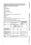
Bar-code wands, laser scanners and CCD touch scanners:
If you are new to scanning, read Appendix K -- Scanning instructions, and then
scan the Test Label at the bottom of the page.
L*
*TEST¯LABE
Credit
Card
Bar Code and MagStripe Slot Scanners:
For a bar-code slot scanner, take the Reader Setup Menu
"A" card and turn it so the A bar code is pointing down
and facing the lighted side of the scanner. Make a
continuous swipe motion through the slot in either
direction.
For a MagStripe slot scanner, take a magnetic-strip card of
the type you will be using, and turn it upside down so the
stripe is pointing down. Move the card through the
scanner in a continuous swipe in the direction of the arrow.
You should hear a beep, and see Test Label displayed on your
screen. (Or an A, if you're using a bar-code slot scanner, or your magneticstrip-card data, if you're using a MagStripe slot scanner.)You should also be able to
type on your keyboard and have the computer respond normally.
If you are unable to read the "TEST LABEL":
• Re-check all your connections.
• Unless you ordered a high-resolution, infrared-light wand, you should see a red
light coming out of the tip of the wand. If you don't see a red light, make sure
the wand's cable is firmly plugged into the WDP Reader.
• Try scanning at several different speeds. The most common mistake is scanning
too slowly; be sure you are "drawing a line" quickly through the code.
• Work through the troubleshooting section beginning on page 30.
TEST LABEL
2-13
Chapter 4
Scanners and Scanning Technique
Wands
Matching your wand to your bar code type
The WDP Reader comes with a low, medium or high-resolution bar code wand, or
a medium-resolution wand specially designed to read through plastic or glass,
depending on your application. The number and letters on your wand's cable
identify its resolution and the type of light it uses -- visible red or infrared (invisible):
•
•
•
•
10 MILRED Low-resolution visible-light
8 MILRED Medium-resolution visible-light
6 MILRED High-resolution visible-light
6 MILIR
High-resolution infrared-light
These are the five types of wands and their associated characteristics:
Low-resolution visible-light wand
This is a low-resolution visible-red LED wand designed specifically for dot-matrix
printed bar codes. It reads any low or medium-resolution bar code printed by any
technology, but can't easily read high density codes.
Medium-resolution visible-light wand
A versatile, general-purpose medium-resolution visible-red LED wand which reads
well-printed dot-matrix bar codes and high-density codes up to 10 cpi for Code 39.
It reads well-printed dot-matrix codes with the same high read rate as the lowresolution wand. With poorly-printed codes, however, the low-resolution wand
significantly outperforms it.
Refocused medium-resolution infrared-light wand
This is a medium-resolution infrared (invisible) light wand designed to read through
plastic or glass 1/100" (.025 mm) to 1/4" (6.35 mm) thick. This is especially useful
for applications such as reading compact disks with the bar codes under the cases. Bar
codes must be printed with infrared-quality ink. Bar codes printed on thermal
printers (not thermal-transfer printers) are often unreadable to infrared light wands.
There is an additional charge of $60 for this wand.
High-resolution visible-light wand
This is a high-resolution visible red light wand designed to read high-density bar
codes up to 13 cpi for Code 39. It can also read any well-printed dot-matrix or other
lower-density codes, providing there are no voids (white spots in the bars) in the
codes.
High-resolution infrared-light wand
This high-resolution infrared-light wand is designed to read high-density bar codes up to
13 cpi for Code 39. It also reads well-printed dot-matrix or other lower-density codes,
providing they're printed with infrared-quality ink (bar codes printed on thermal printers
are often unreadable to infrared scanners) and don't have any voids (white spots in the bars).
3-1
Wand Scanning Technique
Using the illustration as a guide, follow these tips for proper scanning with a wand:
1
Hold the "wand" as you would a pencil,
lightly placing your fingers around the wand.
If you do not see a red light at the tip of the
wand, check to make sure that you are using a
VISIBLE light wand, not an INFRARED light
wand. Infrared wands show no light at the tip of
the wand.
30
2
Your scanning should start in the white
space about ¼" to the left or right of the bar
code. This area is called the "quiet zone". If
you are reading a UPC code with a supplement,
you MUST scan from left to right; otherwise, you
can scan from either direction.
3
You should be holding the wand as if it were
a pencil, approximately 30 degrees from perpendicular. Some bar codes,
especially those that are high density, may require that you adjust the angle of
the wand to be almost perpendicular to the bar code. Starting in the "quiet zone",
quickly and lightly draw an imaginary line through the entire bar code, ending within
the ¼" "quiet zone" at the other end of the bar code. DO NOT scan slowly or press
down hard with the wand - neither one will make it easier to read your bar code.
4
5
Never stop in the middle of the bar code. Pass the wand smoothly across
the bar code, stopping only when you have reached the "quiet zone" at the
other end.
Do not move the wand tip above or below the lines of the bar code. Keep the
wand tip within the confines of the bar code during the entire scan; the whole
point is to draw as straight a line as possible through the middle of the bar code.
To practice scanning, go to the DOS prompt or open up Notepad or a similar
program in Windows or on the Macintosh. Use the Test Label on the next page and
the technique illustration above to practice scanning with your wand. You should
hear an audible beep and see TEST LABEL displayed on computer screen after
every scan. If you do not see TEST LABEL, check your technique, especially the
angle and speed of the scan.
3-2
Using the Bar Code Slot Scanner
Depending on your application, you may wish to use a slot scanner as your bar
code input device instead of or in addition to a wand. Worth Data makes a bar
code slot scanner that plugs into the WDP Reader's Wand port, and is designed for
reading bar codes printed on badges or ID cards. It can also be used for reading
bar codes on file folders, envelopes and any other thin, flat surfaces with bar codes
printed along an edge. There are two types of bar code slot scanners:
• The standard bar code slot scanner is a medium-resolution scanner using
visible-red light. It also reads high-density bar codes.
• Optionally, you can specify a medium-resolution infrared-light scanner.
To read a card or other object with the
bar code slot scanner, orient the card so
that its bar code faces the lighted side of
the scanner. Now make a continuous
wipe motion through the slot.
*TEST¯LABEL*
WDP
.5"
For optimum use with the slot scanner,
bar codes should be printed or applied so
that the center of the bar code is .5"
from the edge of the card.
L*
*TEST¯LABE
The Slot Scanner can be permanently
mounted to a desk or wall through the
threaded mounting holes. If you have ordered only a slot scanner (you don't have
a wand), you will need the WDP Card Setup Deck in addition to the Reader
Setup Menu.
Providing you have Jumper 9 set to wand (the factory shipped default), you can
plug a wand or a slot badge scanner into the Magstripe connector. If you wish to
check the setting of the jumper, refer to page 37 for Jumper Settings.
3-3
Using the MagStripe Slot Scanner
The MagStripe Slot Scanner options (track 1, track 2, track 3, or track 1 and 2 or
2 and 3 or Track 1/2/3) enable the WDP Reader to read credit and other magneticstrip cards without disconnecting or disabling the bar code wand. It's a stationary
scanner which reads tracks 1 and 2 of magnetically-encoded cards meeting the
standards defined by ANSI x 4.13, ANSI x 4.16 1983, ISO 3554 and ISO 2894.
There are three requirements for using a MagStripe Slot Scanner:
• The MagStripe Slot Scanner must be plugged into your WDP Reader's
MagStripe port (next to the Wand port).
• If using a dual or tipple track reader, Jumper 9 must be set to M (for
MagStripe) for dual or triple track scanner instead of W (for Wand or bar code
slot scanner). Single Track Magstripe reading is will work with either the W
or M setting. See Appendix A, Opening the WDP Reader's Case, and
Appendix B, Jumper Settings, for instructions on how to do this. You must
enable the proper track using the WDP Setup Menu as described on page 15.
• The MagStripe scanner can be permanently mounted to a surface using the
threaded holes on the bottom. To use the MagStripe Slot Scanner, turn the
card upside-down so the stripe can be read. Move the card through the
scanner in a continuous swipe in the direction of the arrow.
When the reader makes a good read, it
will beep once and transmit the data
to the computer. Plug the MagStripe
Slot Scanner into the WDP Reader
as shown below, and use the
MagStripe section of the Reader
Pwr
Setup Menu to configure your
reader for your MagStripe
scanner track setting, as described on page 15.
WDP
P11/12
Y-Cable
Wand Magstripe
Credit
3-4
C a rd
Laser and CCD Scanners
Wand scanners can satisfy most bar code reading needs. However, we also offer
Integrated Laser Wedge Readers and the Integrated CCD Wedge Reader (complete
WDP Readers built into a laser scanner and CCD scanner) as well as laser and
CCD scanners that plug directly into WDP Reader wand ports. Laser scanners add
these abilities to the WDP Reader:
• Fast reading of difficult bar codes.
• Reading bar codes from a distance: 1 to 21 inches with Worth Data' model
LZ200, up to 35 feet with the Symbol 3200ER, and typically 3 to 14 inches
with other laser scanners.
• Reading moving objects, such as on an assembly line.
• No-hands operation. Some scanners can be mounted to turn on automatically
when an object passes under them.
• Reading through thick (up to five inches) glass or plastic laminates.
• Reading curved surfaces, such as plastic bags of items.
Warning: These laser scanners use low-power, visible-light laser diodes. Although
momentary exposure to the beam is not known to be harmful, the user should avoid
staring directly into the beam, or shining the beam into people's eyes.
These laser scanners are triggered, 5-volt, visible-light, moving-beam scanners
which attempt to read 36 times per second. If the code misreads ten times, you
don't even know it. Non-triggered hand laser scanners are awkward at best. These
laser scanners are the world's best:
Worth Data LZx00 series
These scanners are manufactured by Worthington using the Symbol 1200 Scan
Engine family. They are very lightweight, easy to handle, rugged, and aggressive
scanners on all types of codes and densities. The scan element has a lifetime
warranty. They are tested with repeated drops at 10 ft. to concrete. The cord has a
1,000,000 bend lifetime.
The LZ200 reads at twice the distance most other lasers read -- 1 to 21" with a 4.2
cpi Code 39 bar code or about 15 inches on a 100% UPC Code. The decode is
very quick. The price is $695. The LZ200-WDP is the same laser with the
decoder built into the scanner, thus eliminating the decoder box. The lower cost
LZ100 reads from 1-14" on the same Code 39 code as above and about 10" from
a UPC code. It has a less powerful laser but it is just as reliable and decodes very
quickly like the more powerful LZ200.
These laser scanners use a low-power, visible laser diode. Although momentary
exposure to a CDRH II laser scanner is not known to be harmful, avoid staring
directly into the beam or shining the beam into other people's eyes. The required
safety label to advise the user of the laser cautions appears on these lasers as shown:
3-5
Remember, even though momentary exposure to these low-power, visible-light
lasers is not known to be harmful, youmust never stare into the beam or aim it into
anyone's eyes. See the following pages for tips on solving problems with laser and
CCD scanners and difficult codes.
AVOID EXPOSURE
LASER LIGHT
IS EMITTED FROM THIS APERTURE
CAUTION
ACHTUNG LASERSTRAHL, LASERCLASSE 2,
NICHT IN DEN STRAHL BLICKEN.
LUMIERE LASER – NE PAS REGARDER
DANS LE FAISCEAU APPAREIL A LASER DE CLASSE 2.
CAUTION – LASER LIGHT WHEN OPEN,
DO NOT STARE INTO BEAM.
IEC CLASS 2 LASER PRODUCT.
680 nM, 1 mW LASER. IEC 825-1:1933/EN60825-1:1994
LASER LIGHT - DO NOT STARE INTO BEAM
680 nm LASER • 1.0 MILLIWATT MAX OUTPUT
CLASS II LASER PRODUCT
product complies with 21 cfr chapter 1, subchapter j.
no user servicable parts.opening voids warranty
DANGER Ð LASER LIGHT WHEN OPEN. AVOID DIRECT EYE EXPOSURE
SEE MANUAL FOR ADDITIONAL PATENT LISTINGS
Worthington Data Solutions ¥ Santa Cruz, CA 95060
The LZ100,LZ200,LZ100-WDP, and LZ200-WDP are covered by one or more of the following U.S. patents:
Patent#:4,360,798; 4,387,297; 4,460,120; 4,496,831; 4,593,186; 4,603,262; 4,607,156; 4,652,750; 4,673,805; 4,736,095;
4,845,350; 4,896,026; 4,897,532; 4,923,281; 4,933,538; 4,992,717; 5,015,833; 5,017,765; 5,021,641; 5,029,183;
5,103,461; 5,113,445; 5,140,144; 5,142,550; 5,149,950; 5,157,687; 5,168,148; 5,168,149; 5,180,904; 5,229,591;
5,235,167; 5,243,655; 5,247,162; 5,250,791; 5,250,792; 5,262,627; 5,280,163; 5,280,164; 5,280,498; 5,304,786;
5,321,246; 5,377,361; 5,367,151; 5,373,148; 5,378,882; 5,396,053; 5,396,055; 5,399,846; 5,404,081; 5,410,139;
5,142,198; 5,418,812; 5,420,411; 5,436,440; 5,444,231; 5,449,891; 5,449,893; 5,468,949; 5,479,000; 5,479,002;
5,504,322; 5,528,621; 5,532,469; 5,543,610; 5,545,889; 5,552,592; 5,578,810; 5,589,680; 5,612,531
4,816,660;
5,047,617;
5,230,088;
5,304,788;
5,410,140;
5,479,441;
A stand is available for all of the Worthington lasers which allows hands free
reading of bar codes. Just before placing the scanner in the stand, scan the bar code
on the stand to set the laser into a automatic reading mode. When a bar code is
presented the narrow searching beam is turned on fully to read the bar code
presented. The stand is available in a mountable goose neck (S10) or in a free
standing version (S20). The stand can also be used with the F86 CCD Scanner
and WDP-P16 Integrated CCD Reader. Below is a drawing showing how the Lx00
Laser Scanner or the Lx00 WDP mounts into the stand with the weighted base.
(The WDP P11/12 must have JP8 set to L for the stand mode to work correctly.
See Appendix B.)
3-6
ND
STA
F
/OF
ON
CCD Scanners
The F86 CCD Scanner or the WDP P16 Integrated CCD Reader can also mount
in the stand, but the bar code must be presented within 0-4" of the scanner. These
quick, durable units(F86 CCD Scanner) work like a laser, but with more limited
range. Just aim the scanner at the bar code and by aligning the top of the rather
wide beam so that it is within the bar code, pull the trigger and a read occurs
instantly. There are 50 scan attempts per second made. This CCD scanner can also
be programmed for triggerless scanning on the WDP by scanning the bar code
below:
STAND ON/OFF
3-7
The Integrated CCD Wedge Reader is a complete WDP Reader built into the F86
CCD Scanner. Just plug it in between your computer and keyboard and you're
ready to go. It works with any PC keyboard-compatible computer and all
Macintosh models.
Tips for using CCD’s and Lasers:
The CCD scanner works best when positioned about 3" from the bar code. The
operating range is about 0-4" for most codes. It can read curved and uneven
surfaces well. Both the CCD and laser scanners are simply aimed straight at the
bar code so that the scanner's beam must cross every bar and space on the bar code,
Right
Wrong
Wrong
without touching any other bar codes, as shown in the first example below.
To read large bar codes with laser scanners, you'll need to hold the scanner further
away to produce a wider beam, and for bar codes with bars very close together,
you'll need to hold the laser scanner closer.
3-8
Laser scanner options:
"Double-scan checking": To minimize the possibility of misreads with very
poorly printed bar codes or when reading through windshields, you have the
option of forcing the WDP to keep reading until it gets two results that are exactly
the same. This "double scan checking" takes a little longer, but it will eliminate
misreads. To activate double scan checking:
Scan Start Setup
Scan Code 39
Scan E to enable double scan checking.
Scan End Setup
To disable double scan checking, scan F instead of E.
4-second beam: Another option with problem reading conditions is to increase
the length of the time the scanner attempts to read, from the default 2-second beam
to a 4-second beam. This would be very helpful using long range scanners which
needs additional aiming or scanning time. To select the 4-second beam:
Scan
Scan
Scan
Scan
Start Setup
2 of 5
F to select the 4-second beam
End Setup
To return to the default 2-second beam, scan E instead of F.
Continuous Scanning Option for the CCD scanner: Sometimes it is desirable to
read sheets or lists of bar codes without having to activate the trigger before each
read. To activate the CCD continuous scanning:
Scan
Scan
Scan
Scan
Start Setup
Computer Interface
B to select continuous scanning
End Setup
To disable continuous scanning, repeat the above, substituting C for B.
To use continuous scanning with a laser scanner, scan D; however, you will have to
hold down the trigger while scanning. In either case, if you want to read the same
bar code twice in succession, you will need to release the trigger and pull it again.
Small quiet zones: Although we recommend quiet zones (white space on either
side of a bar code) of at least 0.25", this option lets the laser and CCD scanners
read bar codes with less than 0.2" quiet zones, the only drawback being an
extremely small increase in the possibility of substitution errors.
Scan
Scan
Scan
Scan
Start Setup
Computer Interface
F to select small quiet zones
End Setup
To return to normal quiet zones, repeat the above, substituting E for F.
3-9
Chapter 4
Special Features
Function and Control Key Support
The WDP Reader can also transmit key sequences for function, control, alt
(command and option keys on Macs), cursor and shift keys, for ease of use with the
many software packages using these keys for menus or commands.
FA or
C128
Code
39
IBM
Key
Mac
Key
FA or
C128
Code
39
IBM
Key
Mac
Key
SOH
STX
ETX
EOT
ENQ
ACK
BEL
SO
LF
CR
SI
DLE
DC1
DC2
$A
$B
$C
$D
$E
$F
$G
$N
$J
$M
$O
$P
$Q
$R
F1
F2
F3
F4
F5
F6
F7
F8
Numpad 5
Enter
F9
F10
Del
Insert
F1
F2
F3
F4
F5
F6
F7
F8
Enter
Return
F9
Cmnd On
Del
Cmnd Off
DC3
DC4
NAK
SYN
VT
FF
ETB
CAN
EM
SUB
FS
GS
RS
US
$S
$T
$U
$V
$K
$L
$W
$X
$Y
$Z
%B
%C
%D
%E
Lft Arrow
Rt Arrow
Dn Arrow
Up Arrow
Pg Up
Pg Down
Home
End
Shift ON
Shift OFF
Control On
Control Off
Alt On
Alt Off
Lft Arrow
Rt Arrow
Dn Arrow
Up Arrow
Pg Up
Pg Down
Home
End
Shift ON
Shift OFF
Control On
Control Off
Option On
Option Off
When the WDP reader reads a Code 128 or Full-ASCII Code 39 (or the equivalent
two-character Code 39 sequences) bar code containing one of the control
characters in the table above, it transmits the appropriate key code(s) for the IBM
or Mac computer interface.
Function keys F1 through F10, and numeric-pad keys
Function keys F1 through F10, and numeric-pad keys (such as Left Arrow and
Del), are encoded by a single control character (or the equivalent two-character
Code 39 sequences) as shown in the table above.
For example, if the WDP Reader reads bar code data of SOH (ASCII 001 -- a
control-A), it will transmit an F1 key sequence to your computer.
Function keys F11 and F12
Function keys F11 and F12 require two characters to be paired to make these
functions keys. The F11 key is created by combining the Null Character (%U in
Code 39) and SOH ($A in Code 39). The F12 key is created by combining the
Null Character (%U in Code 39) and the STX ($B in Code 39).
4-1
Shift, Ctrl and Alt keys
Shift, Ctrl and Alt keys require three sequences
1) The ON code generated when the Shift, Ctrl or Alt key is pressed.
2) The other key to be used in conjunction with the Shift, Ctrl or Alt key.
3) The OFF code generated when the Shift, Ctrl or Alt key is released.
For example, to properly encode a bar code sequence for Ctrl-C, you would create
a bar code of Ctrl ON, C, and Ctrl OFF (control character FS, C and control
character GS).
Windows Key
The Windows key on a Windows keyboard is transmitted by scanning bar codes
%UC for Windows On (pressing down) and %UD for Windows Off (releasing the
key).
Macintosh Command and Option Keys on USB
When you have a WDP Reader attached to a Macintosh Computer's USB port, to
emulate the Command key, you use the Windows key On/Off bar codes (%UC Command On and %UD - for Command Off ) the Alt Key On/Off (%D for
Option On and %E for Option Off ).
If you have an older WDS Reader (before 6/99), you can also imitate the
Command Key by keycodes in the Preamble/Postable. To transmit
Command N would be:`E01F'N`E0F01F'
Transmitting any ASCII character using its 3-digit ASCII code
You can also transmit any ASCII character from 000 to 255 by emulating the IBM
technique of typing a character's ASCII number on the numeric pad while holding
down the Alt key.
For example, to transmit ASCII 250, you would create a bar code of Alt On, Down
Arrow (2 on the numeric pad), Numpad 5, Insert (0 on the numeric pad) and Alt
OFF (control character RS, control character NAK, control character LF, control
character DC2 and control character US).
4-2
Accumulate Mode
Accumulate Mode is an option (which can be enabled or disabled using the Reader
Setup Menu's Code 39 section) allowing the reader to accumulate multiple bar
codes in its buffer, then transmit them to the computer as if they had been a single
bar code. This is useful for entering quantities and other variable data.
It works with Code 39 only, and can't be used with a check digit. When the reader
reads a bar code with a leading space, it beeps and buffers the data without
transmission. It continues to read and buffer bar codes (up to 40 characters) until
it reads a bar code without a leading space. Then the entire buffer (including that
last code) is transmitted as one long bar code. A bar code of a double minus (--)
sign clears the buffer. Scanning a backspace code ($H) backspaces in Full ASCII
mode. A handy code for Enter (as seen on the "Barpad" below) is a Start/Stop only.
(No data.)
This numeric "Barpad" illustrates Accumulate Mode. Scan 5, 3, 8, and Enter.
The reader transmits a single message of 538.
0
1
2
3
4
5
6
7
8
9
Clear
Backspace
CR
Enter
4-3
Chapter 5
Troubleshooting
A reader installed in Wedge mode (external or internal) doesn't beep three
times when you power up your system, or the keyboard locks up, or you
get a "keyboard error" or "301" message.
• Check the cable connections to make sure everything is plugged in securely.
With a PC, make sure the keyboard cable is plugged into the keyboard port
rather than the mouse port. If on a Mac ADB, be sure the tagged end of the
Y cable goes to the ADB port.
• If, after checking the connections, you still have a problem, your computer
and keyboard combination probably doesn't have enough left-over power to
drive the bar code reader also. Disconnect the scanner from the WDP Reader
and reboot your system. If the system boots correctly when the scanner is not
attached, you solve the problem by ordering a 5-volt external power supply
(feature code F10).
• If the system still doesn't boot correctly with the scanner disconnected, a
Worth Data regulated power supply (don't use someone else's power supply or
you will damage the reader)- will probably still correct the problem. If you are
using a USB reader and there many devices, you may need either a power
supply on the WDP, or you may need a powered USB hub device.
The reader won't beep when reading bar codes
Recheck all the connections using the installation section as a guide. Try
• reading a known good bar code - the test label on page 18, following the steps
for scanning in Appendix K. If you're trying to read Code 39 bar codes with
leading spaces (such as the Barpad on page 27) and have enabled Accumulate
Mode, those bar codes will not be transmitted to your computer until you read
a bar code without a leading space. Try reading the Test Label on page 18 as
an example of a known good label.
Reread the configuration section and make your bar code type is enabled.
If it works in the
Magstripe port, the wand port is probably jumpered for laser.
• Switch a wand to the Magstripe Port and try again.
If the read failure is on Interleaved 2 of 5 codes, make sure the data length is
• the same that you selected on the Reader Setup Menu. Be sure you don't have
the check digit enabled for Code 39 or Interleaved 2 of 5 if you're trying to
read data without check digits.
5-1
Extra characters at the beginning or end of your bar code data
• Clear the Preamble and Postamble.
• Make sure you haven't enabled transmission of any start/stop characters,
checksums, leading digits or terminator characters that you don't want
transmitted. For UPC-E, select Compressed transmission if you don't want it
padded with extra zeros.
The reader transmits incorrect data to the screen
• Reread page 12 and make sure you chose the proper Computer Interface.
• If part of the data is correct and part missing, you need to tell the WDP Reader
to transmit data at a different rate. First try Learned Timing on page 12, and
if that doesn't work, resort to changing Data Transmission Timing on page 15.
• If the reader is transmitting punctuation characters (!@#$%^&*) when
reading numeric bar codes, or transmitting letters in the wrong (upper/lower)
case, you may have a Num Lock, Caps Lock, shift or timing problem. Check
your keyboard to see if the Num Lock or Caps Lock keys have been activated.
Finally, try "learned timing" (See Page 12) or changing your Data
Transmission Timing (See page 15).
• If you're using Code 39, read page 16 to see if you've set Caps Lock properly
for your application. If your Code 39 bar codes include punctuation
characters %, $, / or +, the reader is seeing them as part of Full-ASCII Code
39 sequences. Using the Reader Setup Menu, disable Full ASCII Code 39.
Poor read rate
• Try reading the test label on page 18 (following the scanning instructions in
Appendix K) as an example of a known good bar code. Examine your bar
codes to make sure they have dark bars, clearly defined bars and white spaces,
and a "quiet zone" of at least 1/4 inch to the left and right. If the bars are grey,
or so dark that they "bleed" into the white spaces, the person or organization
printing them will need to adjust the printer or get a new ribbon or toner
cartridge for it.
• Carefully follow the scanning instructions Appendix K when reading any and
all bar codes. As straightforward as scanning may seem, many people who call
Worth Data with a complaint about poor read rate are simply not doing it
correctly.
• If you're using an infrared bar code wand, be sure the bar codes you're trying
to read were printed with infrared-quality ink. Make sure you're using the
right type of wand (see page 19) for the type of bar codes you're trying to read.
• Pry the wand tip off; clean the inside with a soft, lint-free cloth. Carefully blow
off any debris from the red plastic lens.
5-2
• Erratic or low read rates can also result with systems that supply unusually low
current or voltage to the keyboard. To test for this, turn your system off,
disconnect the keyboard from the "Y" cable, and turn it back on. Then try
reading the same bar codes. The system will probably be in a keyboard error
state and not display the bar code data on the screen, but all you're interested
in is listening for the beeps that signify good reads. If the WDP Reader has a
much higher read rate without the keyboard attached, you can probably solve
the problem by using a Worth Data regulated 5-volt external power supply
(F10).
Changing the volume of the WDP Reader's beeper:
• First, you need to get to the WDP Reader's circuitboard. If you're using the
Reader in External Wedge mode, you'll need to remove the case, using the
illustration on the next page as a guide. If it's mounted internally, you'll need
to remove the cover to your computer's slot cabinet. Locate the volumecontrol potentiometer using the illustration below. Insert a small screwdriver
into the slot and gently turn it clockwise, to decrease the volume, or
counterclockwise, to increase it. A tiny fraction of a turn makes a big
difference in volume.
5-volt power adapters for external wedge installation:
• The 5-volt adapter (F10 for 110V, F11 for 220V, F14 for UK 220V, and F13
for Australia 240V) is used to power the WDPs with separate decoder box
configurations where the computer supplies unusually-low voltage or current
to the keyboard. Do not plug in this adapter to a WDP Readers installed in
bus mode. Connect the power adapter to the reader as shown below.
• Don't use anything but a Worthington Data Solution's power supply or you
will probably damage the reader. The Worthington Data Solution's power
supply is regulated and has a specific polarity. Almost all other power supplies
are unregulated and will damage the WDP is used. Just because the connector
fits, don't use it.
5-3
open outward l
Appendix A
Opening the WDP Case
Use the illustrations below as a guide while removing the WDP Reader's
circuitboard from its case.
Turn your WDP Reader upside-down, and unscrew its single phillips screw. Insert
unscrew
tilt screw and pull up to open lid
a fingernail, credit card edge or small screwdriver blade into the gap between the
base and side of the case, and gently use it as a lever to lift up the edge of the base.
Then grasp the edge of the base and open it outward like a door.
Grasp the circuitboard by the edge pointed to below, and gently pull up to lift it
out of its case.
If you will be returning the reader to its case (as opposed to plugging it into an
expansion slot), after beeper-volume adjustment or jumper change, do so by
reversing the steps described and pictured on this page.
A-1
Appendix B
ISA Internal Board Installation
Slot Installation with Keyboard Cabling
The WDP Reader can be kept out of the way by removing it from its case and
mounting it in a PC's ISA slot. It can use the slot for physical mounting only, and
doesn't communicate with the bus. Cables connect it between the computer and
keyboard, and bar code data is received via the computer's keyboard port.
Carefully follow these steps to convert the WDP Reader to Internal Wedge
mounting:
1 CAUTION: Your computer's power must be off and its power cord
unplugged before you install the WDP Reader. Attempting to install it with
the power on may give you a severe shock or damage your computer.
2 Remove the reader's case according to the instructions in Appendix A.
3 Using the illustration on the following page for a guide, place the special order
silver mounting bracket onto the end of the board, and use the included screws
to securely attach it to the board.
4 Remove the cover to your computer's slot cabinet according to the procedures
in the owner's manuals.
5 Insert the reader into any unused ISA slot. Be sure it is firmly seated in the
slot. Anchor the board to the computer's case with a screw at the top of the
metal bracket on the card.
6 Replace your computer's slot-cabinet cover according to the procedures in the
owner's manuals.
7 Using the illustration on the following page for a guide, plug the wand, laser
scanner, touch scanner or bar code slot scanner into the WDP Reader's Wand
port. (If you have a MagStripe slot scanner, see page 21.)
8 Using the illustration on the following page for a guide, connect the "Y"
cable's telephone-style jack to the WDP Reader's "Y" Cable port.
9 Unplug the keyboard cable from the back of the computer. Note its location
so you don't accidentally plug into the mouse or cassette port when installing
the "Y" cable.
10 Using the illustration on the following page for a guide, plug the end of the
keyboard cable into the "Y" cable's round female DIN connector.
11 Using the illustration on the following page for a guide, plug the "Y" cable's
male DIN connector into the back of the computer where the keyboard
previously plugged into.
B-1
The connections for Internal Wedge installation on a PC should be as shown
below.
If you have a laser scanner, CCD scanner or bar code slot scanner, it will plug into
the wand port instead of the wand. (If you have a MagStripe slot scanner, see page
21 for its installation instructions.) Be sure to store the WDP Reader's case in a safe
place: If you need the slot in the future, or upgrade to a system without PC-style
expansion slots, you can easily replace the reader in its case for external mounting.
Now turn to page 7 to configure the WDP Reader.
B-2
Slot Installation with Bus Communication
For computers running DOS, the internal WDP Reader can be mounted in any
unused ISA slot and jumpered to communicate with the bus directly. Internal Bus
installation is normally a factory-special order (WDP Model P31/32) which
includes BusKey software but no reader case or Velcro for mounting the case.
Because the WDP Reader is not physically connected to the keyboard, it requires
the program BusKey to read bar code data from the bus and place it into the
keyboard buffer.
See Appendix C for the jumper settings (JP4,JP5, and JP7) necessary to convert the
WDP reader board to communicate directly with the bus.
The DOS program BusKey is used only when the WDP Reader is installed in
Internal Bus mode. BusKey is a memory-resident program (TSR) that works in the
background to read bar code data from the bus and place it into the keyboard
buffer, making it look to your computer and software as if the data had been typed
at the keyboard. Most people will want to put BusKey in their AUTOEXEC.BAT
file for automatic loading at boot time.
Installing BusKey
To copy BusKey onto your system, simply use the DOS COPY command. For
instance, to copy BusKey onto hard disk C:, place the BusKey distribution diskette
into drive A, log into the hard disk directory you want to install BusKey in, and at
the C> prompt type:
Copy A:BusKey.Com /v
BusKey Parameters
When you run BusKey, you need to give it parameters specifying the interrupt and
port address you've set the WDP Reader to. If you're not sure of these, go to
Appendix C and read about setting the interrupt number and port address. The
syntax is:
BusKey P=ppp I=i
where ppp equals the port address in hex, and i equals the interrupt number. For
example, if you've set the WDP Reader to port 240 and interrupt 5, you'd start
BusKey like this:
BusKey P=240 I=5
If you run BusKey with no parameters, it will use the default settings of p o r t
220 and interrupt 3, the equivalent of BusKey P=220 I=3 typed at the DOS
prompt.
See Appendix C for the jumper settings (JP4,JP5, and JP7) necessary to convert the
WDP reader board to communicate directly with the bus.
B-3
Appendix C
Jumper Settings
Your WDP Reader is shipped with its jumpers set to match the configuration
(scanner type, interface method, etc.) you ordered. Why might you need/want to
check or change jumper settings?
If you change your scanner type, or install a second scanning device, you may
• need to change some jumper settings.
• If you're going to install the WDP Reader in Bus Interface mode, you may
need to change the Interrupt Number and Port Address jumpers.
If your WDP Reader or scanner doesn't power up correctly, you should make
• sure the WDP has the correct jumper settings for your configuration.
Open the WDP Reader's case using the instructions in Appendix A.
Interrupt Number jumper JP4, the Interrupt Number jumper:
The WDP Reader in Bus Interface mode can use any one of interrupts 2 though 6.
The default is interrupt 3. Go through the list below to determine which interrupts
are not already in use in your system, and choose one of those. If all interrupts are
already in use, you'll either have to free one up (by disabling COM2 or LPT2 on
your computer, for example) or use the WDP Reader in wedge mode rather than
bus mode.
If your system has any real-time clocks, network boards, bus mice, tape controllers
or other add-on devices installed, they may be using some of these interrupts. If
you have any of these in your system, compare their switch settings to your manuals
to see what interrupts they're using.
Interrupt 2: Don't use this interrupt if you have an AT, 386 or 486 system,
an EGA, or an IBM network adapter.
Interrupt 3: This interrupt is usually used by COM2, the second serial port.
If you don't have a COM2, or an internal modem or other
device set to COM2, you should be able to use it.
Interrupt 4: This interrupt is usually used by COM1, the first serial port. If
you don't have a COM1, or an internal modem or other device
set to COM1, you should be able to use it.
Interrupt 5: This interrupt is used by the hard disk on a PC or XT system, and
LPT2, the second parallel port, on an AT system. You can use it if
you have a floppy-only PC or XT system, or an AT system with only
one parallel port.
Interrupt 6: This interrupt is used by the floppy diskette drive controller.
C-1
JP4 - Interrupt
IRQ 2
IRQ 3
IRQ 4
IRQ 6
IRQ 5
JP5, the Port Address jumper:
The WDP Reader in Bus Interface mode can use any of four different port
addresses: hex 220, 240, 2C0 and 2E0. The default setting is 220, which most
people will be able to use with no problem.
Occasionally a tape controller, bus mouse, network board, real-time clock or other
add-on may be using address 220 (compare add-on board switch settings with the
manuals) and you'll need to choose another.
JP5 - Port Address
220
240
2C0
2 E0
JP7, the Interface Method jumper:
JP7 is the jumper used to select wedge or bus installation. Use the Wedge Interface
setting if you are installing the WDP Reader in external or internal wedge mode.
Use the Bus Interface setting if you're installing it as an internal bus reader.
JP7 - Interface
JP7
W
/
B
Bus Interface
JP7
W
/
B
C-2
Wedge Interface
JP8, the Laser (Decode Light)/Wand jumper:
W Use the W jumper setting if you have a wand, touch scanner or bar-code slot
scanner connected to the Wand port, or if you'll be using a wand and laser
scanner interchangeably with the Wand port. This is the default setting
shipped on the WDP P11/12.
Using a laser scanner with the W setting causes the scanner's decode light to
be on all the time. This means that your laser scanner won't give a visual
indication (flashing decode light) of successfully-read bar codes, but as most
people just listen for the WDP's beep anyway instead of staring at the scanner,
this is unlikely to affect anyone.
L
Use the L jumper setting if you'll be using only a laser scanner with the Wand
port. (As shipped, the decode light is always on. If you change the setting to
L, a wand will no longer work but the laser scanner's decode light will flash as
a bar code is successfully read.
L / W
Wand
Scanner
JP8
L / W
JP8
Laser
Scanner
Decode
Light
JP9, the Wand/Magstripe jumper:
The WDP Reader has a port labeled "MagStripe", for adding a bar-code slot
scanner, MagStripe reader or wand scanner as a second scanning device. However,
the MagStripe port can not be used with laser scanners. If you want to have both a
laser scanner and another scanner (such as a wand) hooked up at the same time,
you must plug the laser scanner into the Wand post and the other scanner into the
MagStripe port.
Set JP9 to M to use a 2 or 3 track Magstripe reader with the MagStripe port, or W
to use a single track magstripe scanner, wand, touch scanner or slot-badge reader
with the MagStripe port.
W
/
M
JP9
W
/
M
JP9
C-3
Appendix D
Specifications for Code 39
Code 39 (or Code 3 of 9) is the de facto standard of
non-retail American industry. It is widely used in the
automotive industry (AIAG specifications) as well as in
government and military applications (LOGMARS
123ABC
specifications). Code 39 is flexible, features a large
character set, variable data length and density, and bi-directional readability. Code
39 is extremely accurate; substitution errors are almost nonexistent. Its character
set consists of numbers 0 through 9, upper case A-Z, and characters Space, $, %. /
+ and -.
The name "Code 39" comes from both the fact that its character set originally
contained 39 characters (it now has 43) and from its structure. Each character is
formed of three wide and six narrow elements, made up of five bars and four spaces.
Code 39's density can vary from a low of .75 characters per inch (cpi) to a high of
9.4 cpi. There should be a ¼" "quiet zone" (white space) to the left and right of
the bar code. Code 39 uses an asterisk (*) as a start and stop character. This
character must precede and follow the data in the bar code. The WDP gives you
the option of transmitting or not transmitting these characters when the bar code
is read.
Exact specifications for Code 39 and other bar code symbologies can be obtained
from ANSI at the address below:
American National Standards Institute
Customer Service
11 West 42nd St.
New York, NY 10036
http://web.ansi.org
document ANSI/AIM BC1-1995
The cost is $36.
D-1
Mod 43 Check Character
Standard Code 39 can be printed with a "Mod 43 Check Character". This Mod 43
check character cannot be used with Full Ascii Code 39. The check character is
derived by assigning a value to each character in the data to be bar coded from the
table as follows:
Char
Value
Char
Value
0
1
2
3
4
5
6
7
8
9
A
0
1
2
3
4
5
6
7
8
9
10
B
C
D
E
F
G
H
I
J
K
L
11
12
13
14
15
16
17
18
19
20
21
Char
Value
M
N
O
P
Q
R
S
T
U
V
W
22
23
24
25
26
27
28
29
30
31
32
Char
X
Y
Z
.
Space
$
/
+
%
Value
33
34
35
36
37
38
39
40
41
42
Here is an example to illustrate how the check character is calculated for bar code
data of 123XYZ:
1. Take the sum of the values assigned to each character:
1 + 2 + 3 + 33 + 34 + 35 = 108
1
2
3
X
Y
Z
2 Divide the sum by 43: (thus the name modulus 43)
108/43 = 2 with a Remainder of 22
3. Find the character corresponding with the remainder.
M (value 22) is the CHECK CHARACTER
The data becomes 123XYZM, with M added as the Mod-43 check character.
D-2
Full ASCII Extension to Code 39
"Full-ASCII Code 39" expands the Code 39 character set to include all 128 ASCII
characters. Symbols 0-9, A-Z and punctuation characters . and - are identical to
their Code 39 representations. Lower-case letters, additional punctuation
characters and control characters are represented by sequences of two Code 39
characters.
This table depicts the Full ASCII character set as a function of Code 39 characters:
ASCII
C39
ASCII
C39
ASCII
C39
ASCII
C39
NUL
SOH
STX
ETX
EOT
ENQ
ACK
BEL
BS
HT
LF
VT
FF
CR
SO
SI
DLE
DC1
DC2
DC3
DC4
NAK
SYN
ETB
CAN
EM
SUB
ESC
FS
GS
RS
US
%U
$A
$B
$C
$D
$E
$F
$G
$H
$I
$J
$K
$L
$M
$N
$O
$P
$Q
$R
$S
$T
$U
$V
$W
$X
$Y
$Z
%A
%B
%C
%D
%E
SP
!
“
#
$
%
&
‘
(
)
*
+
,
.
/
0
1
2
3
4
5
6
7
8
9
:
;
<
=
>
?
Space
/A
/B
/C
/D
/E
/F
/G
/H
/I
/J
/K
/L
/M
/N
/O
0
1
2
3
4
5
6
7
8
9
/Z
%F
%G
%H
%I
%J
@
A
B
C
D
E
F
G
H
I
J
K
L
M
N
O
P
Q
R
S
T
U
V
W
X
Y
Z
[
\
]
^
_
%V
A
B
C
D
E
F
G
H
I
J
K
L
M
N
O
P
Q
R
S
T
U
V
W
X
Y
Z
%K
%L
%M
%N
%O
‘
a
b
c
d
e
f
g
h
i
j
k
l
m
n
o
p
q
r
s
t
u
v
w
x
y
z
}
|
{
~
DEL
%W
+A
+B
+C
+D
+E
+F
+G
+H
+I
+J
+K
+L
+M
+N
+O
+P
+Q
+R
+S
+T
+U
+V
+W
+X
+Y
+Z
%P
$M
%R
%S
%T,%X
See page 28 for instructions on encoding Function, Control, Alt and Shift
keys with Full-ASCII Code 39 bar code characters.
D-3
Appendix E
Codabar
a29934567a
Codabar is widely used in libraries, blood banks, the
cotton industry and transportation industries. Its'
character set consists of numbers 0 through 9, and
punctuation characters + . - / : and $. Symbols a, b, c,
d, t, n, * and e are used as start and stop characters.
Characters are constructed of four bars and three spaces.
Codabar is a numeric-only code, but different combinations of start and stop
characters can be used to identify different types of labels. Codabar's variable data
length and extremely low error rate make for a versatile bar code.
Codabar start/stop transmission
The Codabar section on the WDP Setup Menu lets you determine whether
Codabar start/stop characters are transmitted or not. If you are varying start/stop
characters with different types of labels, you'll want to "Enable Stop/Start character
Transmission". Start/stop character transmission can also be helpful if you want
your program to differentiate between data coming from the WDP reader and data
coming from the keyboard. If neither of these situations apply, you'll probably
want to disable it.
E-1
Appendix F
Code 128 Specifications
Code 128 is a very powerful bar code, combining an
extensive character set and variable length with
compactness and error checking. The character set contains
all 128 ASCII characters with each character made up of
three bars and three spaces. Each element (bar or space)
AB123456
varies from one to four units in width, totaling 11 units of
width per character. Code 128 contains two levels of error checking:
Each character is checked for internal parity, and
The last character is a checksum.
Code 128 has three subsets, A, B and C. Subset A contains alphanumeric characters
and unprintable control characters, subset B contains alphanumeric characters plus
printable control characters and subset C contains only numeric characters and uses
a 2-character encoding scheme to create a more compact bar code. Code 128 uses
an internal Mod 103 check character that is not displayed by the bar code reader.
Code 128 bar codes can be made up of only one subset or may be a combination
of several.
The Code 39 features of Accumulate Mode, Caps Lock ON and Caps lock OFF also
apply to Code 128.
UCC-128/ EAN-128
UCC-128/EAN-128 Code is a subset of Code 128 adopted by the UCC and EAN
council's for use as a shipping label symbology. UCC/EAN-128 bar codes always
start with a Function Code 1 character. In addition, all variable length fields are
terminated by a Function Code 1 character unless they are the last field in the bar
code.
The WDP outputs the following for the special function codes and start sequences:
]C1
Start C/Function Code 1
^]
(GS) Function Code 1 as a variable string terminator
If MOD 10 UCC 128 is enabled, theWDP expects only 20 digit, numeric-only
128 codes starting with a Function 1 character and terminating with a MOD 10
Check Digit. This is to comply with the Uniform Code Council's Serial Shipping
Container Code specification. The Mod 10 Check digit is calculated the same as
the Interleaved 2 of 5 example in Appendix D. It is the MOD 10 check digit that
distinguishes the Serial Shipping Container Code from other UCC /EAN 128 bar
codes.
F-1
MOD 10 UCC 128 is enabled by scanning the appropriate bar codes on the
TriCoder Setup Menu or by keypad in the PROGRAMMING MODE "Change
Setup" option. If MOD 10 UCC 128 is enabled, you will NOT be able to read a
standard Code 128 bar code that does not have the Function 1 character and the
Mod 10 check character.
UCC/EAN Code 128 Serial Shipping Container Code
The UCC 128 specification is used extensively by the retail industry. If you have a
requirement for a UCC 128 Serial Shipping Container bar code, be sure to follow
the specification as closely as possible as many vendors will impose fines for nonconformance. For more information on UCC 128, contact the Uniform Code
Council at:
Uniform Product Code Council, Inc.
8163 Old Yankee Road, Suite J
Dayton, Ohio 45458
(513) 435-3870
Many of the specifications are available online at:
http://www.uc-council.org
F-2
Appendix G
Interleaved 2 of 5 Code
Interleaved 2 of 5 Code is a numeric-only, even-number-ofdigits bar code. It is widely used in warehouse and industrial
applications. A combination of five elements, two wide and
three narrow represent each character. Odd-number
123456
position digits are encoded in the bars, even-number
positions in the spaces.
Interleaved 2 of 5 Code is so susceptible to partial scans being interpreted as valid
reads that we recommend at least one of the following safeguards:
Use one length of I 2 of 5 code. Using one length of data allows you to tell the
TriCoder to look for one length of I 2 of 5 code only. By default, the TriCoder
is set to look for a 6 digit I 2 of 5 code but you can set the length to something
different using the TriCoder Setup Menu. Setting the length to 00 digits
allows variable length bar codes scanning. If you must use the 00 setting, we
recommend that you then use the "Minimum/Maximum" data length field
when creating a program in the TriCoder to check each field for the proper
length.
Use a check digit. Worth Data's LabelRIGHT printing program automatically
calculates and prints a check digit upon request using the method below:
Interleaved 2 of 5 Mod 10 check digit calculation
1. Assume that the bar code data is 1987.
2. Starting with the least significant digit (in this case, a 7), label the digits
alternatively even and odd.
7
8
9
1
3.
-
even
odd
even
odd
Take the sum of the odd digits:
8+1=9
4. Multiply the sum of the even digits by 3:
(7 + 9) x 3 = 48
G-1
5.
Add the results of steps 3 and 4:
9 + 48 = 57
6. Subtract the result of step 5 from the next highest multiple of 10:
60 - 57 = 3
7. The checksum becomes the low-order digit:
19873
8. Because the data now has an odd length, a leading zero is added, for the final
result of:
019873
G-2
Appendix H
UPC Specifications
t56789rDEFG>W
+67L9NOrFG?@A?u
UPC symbols are found on almost all grocery products
and many other retail items. The UPC code most people
are familiar with (UPC-A) is a fixed-length (12 digits)
numeric only code, with the first digit controlled by UPC
coding assignments and the last digit a checksum. UPCE and UPC-E1 are variations of the standard UPC-A
code. Each digit is constructed of two bars and two spaces. UPC has very precise
standards of code size, structure, and numbers to be used.
EAN is an international superset of UPC. EAN-13
has 13 digits, with the first two digits representing a
country code. The final digit is, as with UPC, a check
digit. EAN-8 is a shorter version on the EAN-13 code
containing seven data digits and ending again with a
checksum.
The exact UPC/EAN symbol specifications are
available from:
Uniform Product Code Council, Inc.
8163 Old Yankee Road, Suite J
Dayton, Ohio 45458
(513) 435-3870
Specifications are also available via the internet at:
http://www.uc-council.org
Keep the following guidelines in mind when printing UPC bar codes:
If you plan to use a "supermarket-type" in-counter scanner to read the codes,
specify a bar code height of at least .9" for an optimal first read rate.
Make it an early practice to observe the numbering conventions of the UPC
Council. Do not label unmarked merchandise with a bar code whose numbers
may conflict with those already assigned. If products with these numbers are
not in your store now, they are likely to be in the future, causing conflicts in
your inventory system.
H-1
The leading Number System Character, (the first number of the 11 digits to be
entered) should conform to these UPC assignments:
0,6,7
Regular UPC 12 digit codes with numbers assigned by the UPC
Council. (Do not use 0 as the leading number for in-store marking).
2
Store-marked random weight items of meat and produce.
3
Reserved for National Drug Code and Health Related Items.
4
Use this leading digit for in-store marking of non-food items.
5
Reserved for coupons. Do not use this today, or you will not be able
to process coupons through your system tomorrow.
UPC 2 and 5-character supplemental codes
The UPC standards include the addition of a 2 or
5-character supplemental code used with
magazines and paperback books. To read the
supplements, you must first enable them using the
TriCoder Setup Menu.
NOTE: Enabling the supplements disallows the reading of UPC codes from right to
left to assure that the supplement does not get missed.
ISBN Specifications
ISBN (International Standard Book Numbering) bar codes are essentially EAN-13
with a 5 digit supplement, where the first 3 digits are the Bookland country codes
of 978 for books and 977 for periodicals. Although the bar code contains 18
characters, the ISBN format uses only 9 of them, along with a newly calculated
Mod-11 check digit. For example, a bar code containing the numbers
978055337062153495 would transmit as 0553370626 in the ISBN format. The
TriCoder has the option of transmitting in the ISBN format.
ISBN 0-553-37062
H-2
ISBN specifications are available from:
American National Standards Institute
Customer Service
11 West 42nd St.
New York, NY 10036
http://web.ansi.org
document ISO 2108:1992 $26.00
The UPC/EAN checksum character
The last character in a UPC-A, UPC-E, UPC-E1, EAN-13 or EAN-8 bar code is
the checksum. For reference, these are the methods of calculation:
Checksum calculation for UPC-A, EAN-13 and EAN-8
Use Worth Data’s phone number (it's not a real UPC-A code) as sample data:
18314589938
Assign even and odd positions, starting at the right and moving left:
8
3
9
9
8
5
4
1
3
8
1
odd
even
odd
even
odd
even
odd
even
odd
even
odd
1. Starting with the leading digit, 8, take the sum of all the characters in the
odd positions.
8 + 9 +8 + 4 + 3 + 1 = 33
2. Multiply the result of step 1 by 3.
33 x 3 = 99
3. Now take the sum of all the even-position characters.
3 + 9 + 5 + 1 + 8 = 26
4. Add the result in Step 2 to the result in Step 3.
99 + 26 = 125
5. Subtract the result from the next higher multiple of 10.
Next higher multiple of 10 over 125 = 130
130 - 125 = 5
5 is the Modulo-10 check character. The data to be printed becomes:
183145899385
This same formula is used for EAN-13 (using the 1-12 digits) and EAN-8 (using
the 1-7 digits).
H-3
UPC-E Checksum Calculation
Use the sample data of 123456 to demonstrate the UPC-E checksum calculation:
1. The 6 digit UPC-E code is converted to a 10-digit code, using an expansion
scheme based on the sixth digit:
If the code
ends in:
0
1
2
3
4
5
6
7
8
9
UPC-E data
Insertion digits
abcde0
abcde1
abcde2
abcde3
abcde4
abcde5
abcde6
abcde7
abcde8
abcde9
00000
10000
20000
00000
00000
0000
0000
0000
0000
0000
Insertion
Position
3
3
3
4
5
6
6
6
6
6
10 digit
code
ab 0 0 0 0 0 cde
ab1 0 0 0 0 cde
ab2 0 0 0 0 cde
abc0 0 0 0 0 de
abcd 0 0 0 0 0 e
abcde 0 0 0 0 5
abcde 0 0 0 0 6
abcde 0 0 0 0 7
abcde 0 0 0 0 8
abcde 0 0 0 0 9
Because the sample UPC-E code ends in a 6, the insertion digits 0000 are inserted
at the sixth digit (insertion position 6):
1234500006
2. Add the Number System Character of 0 to the sample data:
01234500006
3. Use the UPC-A check digit calculation described in the previous section to
produce a check digit as if it were a UPC-A code. The check digit for the
sample data is:
5
4. The complete 8 digit code consists of the Number System Character, the
original 6 digit code and the check digit:
01234565
H-4
Appendix I
MSI/Plessey Specifications
Plessey is a variable length numeric only bar code. MSI Bar Code is a variable
length, numeric-only code with an automatically appended Modulus 10 check
digit. MSI is sometimes called Modified Plessey Code. If the user specifies an
additional check digit, the MSI code can be 14 digits long, otherwise it has a
maximum length of 13 characters. This is how the MSI check digit(s) are
calculated:
The MSI Mod 10 check digit is calculated as follows:
The example bar code data is:
82345
1. Form a number from the odd positions, starting in the units position.
835
2. Multiply the new number by 2
(835) x 2 = 1670
3. Add the digits of product
1 + 6 + 7 + 0 = 14
4. Add the even digits of the original number to the result in 3
2 + 4 + 14 = 20
5. Subtract the result from the next highest multiple of 10
20 - 20 = 0
6. New Check Digit
0
7. Data with check digit is:
823450
I-1
The MSI Mod 11 check digit is calculated as follows:
The example bar code data is:
943457842
1. Assign a checking factor to each number, starting with the units position of
the number (in this example, the 2) up to the highest order position (the 9).
Use checking factors of:
2,3,4,5,6,7,2,3,4,5,6,7...
2. Multiply the checking factor with its assigned number and add the products:
4 + 12 + 32 + 35 + 30 + 28 + 6 + 12 + 36 = 195
3. Divide the sum by 11
195/11 = 17 remainder 8
4. Subtract remainder from 11
11 - 8 = 3
5. New Check Digit
3
(If the remainder is 10, no check digit is added.)
6. Data with check digit is:
943457823
I-2
Appendix J
Code 93 Specifications
Code 93 is variable length, continuous, bi-directional, compact code. Code 93 is
an alphanumeric bar code which consists of 43 data characters (0-9,A-Z,$/+%.and Space), 4 control characters, and a unique start/stop character. The entire set
of 128 ASCII characters is represented in Code 93 using combinations of control
characters and data characters.
%
/ a n d + . Full ASCII 93 is created
The control characters are $
by pairing these control characters with normal data characters. It is almost
identical to the pairings for Code 39; Code 39 uses
$M to produce a
Carriage Return (ASCII 13) character -- Code 93 uses $ M to produce the
Carriage Return.
Code 93's two built-in check digits greatly minimize the possibility of reader
substitution errors. These check digits are never transmitted by the bar code reader.
Code 93's Start and Stop characters are also never transmitted.
If you have not decided which bar code type to use for your application and are
considering using Code 93, while we agree that Code 93 is an excellent code, we
believe that Code 128 is generally preferable because:
1. Code 93 does not have the numeric compression capability that 128 does,
and
2. Code 93 requires pairings to make all Full ASCII characters while 128 does not.
J-1
Appendix K
ASCII Code Equivalent Table
The 128 ASCII codes and their 3 digit decimal equivalents are detailed in the
table below.
Char hex ASCII
NUL
SOH
STX
ETX
EOT
ENQ
ACK
BEL
BS
HT
LF
VT
FF
CR
SO
SI
DLE
DC1
DC2
DC3
DC4
NAK
SYN
ETB
CAN
EM
SUB
ESC
FS
GS
RS
US
00
01
02
03
04
05
06
07
08
09
0A
0B
0C
0D
0E
OF
10
11
12
13
14
15
16
17
18
19
1A
1B
1C
1D
1E
1F
000
001
002
003
004
005
006
007
008
009
010
011
012
013
014
015
016
017
018
019
020
021
022
023
024
025
026
027
028
029
030
031
Char
SP
!
“
#
$
%
&
‘
(
)
*
+
,
.
/
0
1
2
3
4
5
6
7
8
9
:
;
<
=
>
?
hex ASCII
20
21
22
23
24
25
26
27
28
29
2A
2B
2C
2D
2E
2F
30
31
32
33
34
35
36
37
38
39
3A
3B
3C
3D
3E
3F
032
033
034
035
036
037
038
039
040
041
042
043
044
045
046
047
048
049
050
051
052
053
054
055
056
057
058
059
060
061
062
063
Char
@
A
B
C
D
E
F
G
H
I
J
K
L
M
N
O
P
Q
R
S
T
U
V
W
X
Y
Z
[
\
]
^
_
K-1
hex ASCII
40
41
42
43
44
45
46
47
48
49
4A
4B
4C
4D
4E
4F
50
51
52
53
54
55
56
57
58
59
5A
5B
5C
5D
5E
5F
064
065
066
067
068
069
070
071
072
073
074
075
076
077
078
079
080
081
082
083
084
085
086
087
088
089
090
091
092
093
094
095
Char
‘
a
b
c
d
e
f
g
h
i
j
k
l
m
n
o
p
q
r
s
t
u
v
w
x
y
z
}
|
}
~
DEL
hex
60
61
62
63
64
65
66
67
68
69
6A
6B
6C
6D
6E
6F
70
71
72
73
74
75
76
77
78
79
7A
7B
7C
7D
7E
7F
ASCII
096
097
098
099
100
101
102
103
104
105
106
107
108
109
110
111
112
113
114
115
116
117
118
119
120
121
122
123
124
125
126
127
Appendix L
Firmware Upgrades
open outward li
This section applies only to the WDP P11/12 and the WDP P01, the separate external
box decoder models. It does not apply to the Integrated WDP Models.
Occasionally it will be necessary to get firmware fixes for problems discovered with
the external WDP Reader, especially in the early stages of each advance in
development. This is accomplished replacing the EPROM, a chip which is to
replace the similar chip on the board of the WDP's decoder box. The EPROM
chip on the board is labeled with a white paper label to indicate the firmware
version and to communicate the "Copyright Notice".
To replace the EPROM, remove the cover to the WDP decoder box according to
instructions in Appendix A (see the diagram below).
unscrew
tilt screw and pull up to open lid
If you have a Integrated models of the WDP, you will have to send the unit back
for a firmware change at the factory.
Remove the EPROM by gently prying with a small flat head screw driver -alternate ends to keep from bending the metal legs.
Eprom
Worthington Data Solutions
79 WDP 5207
L-1
Before inserting the new EPROM, notice that the EPROM has a small groove in
one end; the end with the groove in it must match the groove in the socket which
it is to be inserted into. Don't insert the chip backwards -- line up the groove in
the chip to be on the same side as the socket's groove.
You may need to slightly bend into the center the legs of the EPROM so that they
can be inserted into the socket. Place the chip into the socket and begin to lightly
push the chip into the socket. Unless you check, you may bend one of the leads
not in a hole underneath the chip -- making your Reader disfunctional. Once you
are sure all legs are positioned into the holes correctly, you can push hard until the
chip is firmly positioned into the socket.
After turning the re-powering the WDP by plugging back in the "Y-Cable", you
should hear 3 beeps. This indicates that the EPROM has been successfully
installed. If it doesn't beep three times, immediately unplug the "Y-Cable" and
remove the EPROM and check for bent legs. Also be certain you have not placed
it in upside down, (not matching the notches). If you have placed it upside down
and were a little slow in removing power, you probably have burnt out the EPROM
and will have to replace it before proceeding.
L-2