1
Worth Data Inc.
Wireless Reader Manual
01/05
The radio equipment described within this manual has been tested and found
to comply with the limits for a Class B digital device, pursuant to Part 15 of
the FCC Rules. These limits are designed to provide reasonable protection
against harmful interference in a residential installation. This equipment
generates, uses and can radiate radio frequency energy and, if not installed and
used in accordance with the instructions, may cause harmful interference to
radio communications. However, there is no guarantee that interference will
not occur in a particular installation. If this equipment does cause harmful
interference to radio or television reception, which can be determined by
turning the equipment off and on, the user is encouraged to try to correct the
interference by one or more of the following measures:
•
Reorient or relocate the receiving antenna.
•
Increase the separation between the equipment and receiver.
•
•
Connect the equipment into an outlet on a circuit different from that to
which the receiver is connected.
Consult the dealer or an experienced radio/TV technician for help.
Shielded cables and I/O cords must be used with this equipment to comply
with the relevant FCC regulations.
Changes or modifications not expressly approved in writing by Worth Data
Inc. may void the user's authority to operate this equipment.
This device complies with Part 15 of the FCC Rules. Operation is subject to
the following two conditions: (1) this device may not cause harmful
interference, and (2) this device must accept any interference received,
including interference that may cause undesired operation.
If you remove the circuit card from the Base Station to place it in other
enclosures, it is your responsibility to obtain the necessary approval, (i.e.,
FCC, CE,BZT,ART,RA), for use of the card in the new enclosure.
This manual contains confidential and proprietary information and is
copyrighted. All rights are reserved. No part of this manual may be
photocopied or reproduced in any form without the prior written consent of
Worth Data Inc., Inc.
Table Of Contents
Introduction ..................................................................................................... 1
Installation........................................................................................................ 2
Configuring the Wireless Scanner ................................................................. 9
for your computer and application ................................................................ 9
Test the Reader with your computer ........................................................... 24
Radio Considerations .................................................................................... 26
One-Way Operating Considerations ........................................................... 26
2-Way Laser Operating Instructions ........................................................... 27
Accumulate Mode .......................................................................................... 29
Function/Control Key Support .................................................................... 30
Troubleshooting ............................................................................................. 33
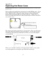
Opening the Base Case.................................................................................. 37
Jumper Settings ............................................................................................. 38
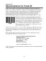
Specifications for Code 39............................................................................. 39
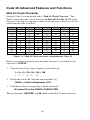
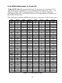
Code 39 Advanced Features and Functions ................................................ 40
Code 93 Specifications................................................................................... 42
Codabar Specifications ................................................................................. 43
Codabar start/stop transmission ................................................................... 43
Code 128 Specifications................................................................................. 44
Interleaved 2 of 5 Code ................................................................................. 46
UPC Specifications ........................................................................................ 48
ISBN Specifications..................................................................................... 49
The UPC/EAN checksum character ............................................................ 50
Checksum calculation for UPC-A, EAN-13 and EAN-8 ............................ 50
UPC-E Checksum Calculation..................................................................... 51
MSI/Plessey Specifications............................................................................ 52
Changing Batteries ........................................................................................ 54
Firmware Upgrades....................................................................................... 55
Index ............................................................................................................... 57
01/05
Introduction
The Worth Data Wireless Readers include the following products:
1)
The LZ202-RF Laser Scanner and the LI102-RF Linear Imager CCD
Scanner both have a range of 100 ft. and are 2-way products that provide
a confirmation beep in the scanner to indicate the Base Station has
received the data. For the US and Canada, the LZ202-RF and the LI102RF operate on four frequencies at 49MHz. For all of Europe, the LZ212RF and the LI112-RF operate on three frequencies at 40MHz. A 2-way
Base Station (B58/B68 for US and B59/B69 for Europe) can support
from 1-8 of the 2-way RF Lasers or RF Linear Imager CCD Scanners.
2)
The LZ200-RF Laser Scanner and the LI101-RF Linear Imager CCD
Scanner are 1-way scanners with 100 ft. range. The LI101-RF and
LZ200-RF are approved for license-free operation in the US and Canada
with the B52/B62 Base Station on four frequencies (49MHz). The L60L
and the LI111-RF are approved for license-free operation on three
frequencies with the B54/B64 Base Station at 40.66MHz in continental
Europe.
•
The LZ200-RF Laser (L60L in Europe) and the LI101-RF Linear Imager
CCD (LI111-RF in Europe), transmit to a base station that attaches to the
keyboard port of a PC or Mac, or any computer's serial port. These 1way products require the user to listen for a beep at the Base Station to
know that the Base has received the transmitted data. The 2-way RF
products (LZ202-RF Laser, LZ212-RF Laser, LI102-RF Linear Imager
CCD, and LI112-RF Linear Imager CCD) have a built-in transceiver and
can thus receive an acknowledgement from the base of received data.
•
The R/F Readers can read and discriminate between Code 39, Full ASCII
Code 39, Interleaved 2 of 5, Codabar, Code 128, EAN-13, EAN-8, UPCE, UPC-E1, UPC-A, MSI, LabelCode4, LabelCode5, Code 93 and
Plessey.
•
All scanners have user replaceable batteries. The battery life for the
LZ200-RF 1-Way RF Laser and the LI101-RF 1-Way RF Linear Imager
CCD is approximately 70,000 scans per set (4) of AA alkaline batteries.
The battery life for the LZ202-RF 2-Way Laser and LI102-RF 2-Way RF
Linear Imager CCD is approximately 50,000 scans per set (4) of AA
alkaline batteries.
1
Installation
Components of Wireless Readers
In the event the shipping box shows damage on arrival, please note the
damage on the carrier's receipt log.
The supposed contents of your Reader shipment is the following:
1.
An R/F Base Station.
2.
An antenna that attaches to the back BNC connector of the R/F Base
Station/Decoder box. The 2-way RF Scanner Base Station uses a second
antenna that mounts in the center of the Base Station.
3.
The Velcro strips can be used to conveniently attach the reader to the side
of your computer, monitor or desk.
4.
A "Y" cable for attaching the Base Station between your computer and
keyboard, OR a serial cable for serial attachment. If you ordered a F30/1
cable, it is convertible to PC or PS/2. If you have a USB only Mac or PC,
you should have a Wedge Saver and C20 cable instead of a "Y" cable.
5.
A wireless scanner, (Laser or Linear Imager CCD). Included is a rubber
boot housing to place over the Laser or Linear Imager for durability.
6.
A Laser/Linear Imager CCD holder.
7.
A laminated Wireless Reader Setup Menu sheet.
8.
If a serial interface model was ordered, a Worth Data 5v regulated power
supply. DON'T USE ANY OTHER POWER SUPPLIES OR YOU
WILL BURN UP THE BASE STATION.
9.
A plastic barpad for entering variable quantity information and
performing the Link Test without data transmission.
Make sure you have a base and scanner with matching frequencies. First, the
color of the antenna tip of the Laser or Linear Imager CCD scanner should
match the color of the label on the underside of the base station. Also, the color
of the label on the underside of the Laser or Linear Imager should match the
color of the label on the underside of the base station, (black/black,
yellow/yellow, red/red, orange/orange, purple/purple, grey/grey, or brown/brown
matched).
2
•
If you are installing on a PC or Mac with traditional keyboard
connectors, proceed to the next section describing keyboard wedge
installation.
•
If you have a USB only PC or Mac, proceed to page 5.
•
If you have an R/F Serial Reader and wish to install to a dedicated
serial port, turn to page 6.
•
If you have an R/F Serial Reader and wish to install between a
terminal and a host computer in a multi-user system (such as UNIX)
to turn to page 7.
Keyboard Wedge Installation:
This section applies for attachment to PCs that have a 5-pin din or 6 pin minidin keyboard port or to a Mac with an ADB port. If your computer only has a
USB port for keyboard attachment, proceed to page 5.
99% of computer keyboard ports have enough power to support the Base
Station without needing the Worth Data external power supply. Therefore, the
power supply is an optional extra charge feature.
DO NOT PLUG ANY OTHER POWER SUPPLY into the Base Station,
or it will be “fried” (burned up).
1.
Power down the computer. Turn OFF the power on the computer.
Failure to power down risks blowing (shorting) a trace on the computer.
2.
Unplug the keyboard cable from where it plugs into the computer.
3.
Plug the keyboard cable into the "Y" cables’ round female DIN connector.
The F30/1 "Y" cable is convertible from 5 pin to 6 pin by simply
removing the connector from one end of the "Y and attaching it to the
other end. The F42 for the Mac is not convertible.
4.
With the power OFF on the computer, Plug the "Y" cable’s male DIN
connector into the back of the PC where the keyboard previously plugged.
DON'T PLUG INTO THE MOUSE PORT by mistake!
5.
Plug the telephone-style jack at the bottom end of the "Y" cable into the
Computer Port of the RF Base Station.
6.
For RF Base Stations, attach the telescoping antenna to the BNC
connector on the back of the case. For a 2-Way Base Station, you must
also screw in the fixed length black transmitter antenna to the center of the
Base Station.
3
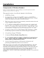
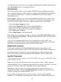
Your computer, keyboard and reader should now be cabled as shown below:
Turn on your computer:
You will hear three beeps on the 1-way Base Stations, and the LED on the
front will change from red to green, indicating that the Base Station is
functioning correctly. The 2-way base will simply flash to green. If you have a
PS/2 or a Mac, you will have to change the Computer Interface using the
Wireless Setup Menu. Turn to page 9 to configure your RF Reader using the
Wireless Setup Menu.
4
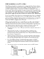
USB Installation on a PC or Mac:
The USB port should have enough power to support the Base Station without
needing the Worth Data external power supply. Therefore, the power supply is
an optional charge feature. If you are connecting your Base Station to a
portable computer (laptop or notebook), it is likely you will need to order our
power supply. Most newer portables (all Macs and most PC-compatibles) may
see the power draw by the USB device as too high and drop power to the USB
port altogether. Use ONLY the Worth Data power supply. Don't plug any
other power supply into the Base Station, or it will be “fried” (burned up).
If you are attaching a Base Station to a computer that doesn't have a traditional
keyboard port (a 5 or 6 pin din on a PC, or an ADB on Mac), but only a USB
port for attaching a keyboard, then you must use the Wedge Saver to attach the
Base Station to the USB port. The Wedge Saver is ordered in lieu of a "Y"
Cable; the USBW is shipped with a C20 cable.
When you plug the Wedge Saver to the USB port on a Mac or PC, Windows
98, ME, XP, and 2000, the device will be sensed will sensed and installed.
Windows finds the necessary driver, usually on the hard drive; you don't need
any additional drivers other than what is already on Windows or Mac OS.
After the software installation completes, follow these instructions:
1.
Plug the Wedge Saver into a USB port on the host computer, keyboard, or
a USB hub.
2.
Then plug the C20 cable, (a cable with an RJ45 “telephone style”
connector on one side and a 6 pin mini-din connector on the other),
between the Base Station and the Wedge Saver. Plug the RJ45 end into the
Base Station's Computer Port.
3.
The Base Station should power up. 1-Way Base Stations will beep three
times and the light on the front will turn green. The 2-Way Base Station
does not beep; the light simply turns to green on successful power up.
4.
For 1-Way RF Base Stations, attach the telescoping antenna to the BNC
connector on the back of the case. For a 2-Way Base Station, you must also
screw in the fixed length black transmitter antenna to the center of the Base
Station.
5.
You are now ready to scan into the computer using your RF Scanner.
5
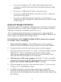
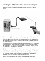
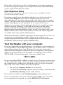
Installing the R/F Reader with a dedicated serial port
The Base Station can be directly attached to a spare serial port as shown
below.
Your software will need to read the serial port as a separate device, unless
you're using an IBM-compatible computer and Worth Data’s PortKey
software, which makes serial-port data appear as though it had been typed at
the keyboard. See page 28 for a simple BASIC program to read the serial port
for testing purposes.
If you specified a 25-pin null-modem cable (part number F34) or a 9-pin cable
(part number F36) when you placed your order, you can cable directly from
the RF/Reader's Y-Cable port to your computer's serial port. Refer to page 8
for the details of the pin-outs of the cables.
Serial extension cables longer than 80 feet can cause system lockups in
Windows unless you make sure that pins 4,6,7 and 8 are cut on the 9-pin end
of the F36 cable, and pins 4,5,6,8, and 20 are cut on the 25-pin end of the F34
cable. All F36 and F34 cables shipped after 9/15/01 already have these pins
cut. If you are building your own cables or have questions on which pins
should be active, see page 8 for details on cable pin-outs.
Turn to page 9 to configure the Wireless Reader using the Setup Menu.
6
Installing the R/F Reader between a computer and
terminal
If you attach the Wireless Base between your computer and a terminal, as
shown below, using Cable Selection F45-1, bar code data will be sent to the
computer as if it had been typed on that terminal. Refer to page 8 for the
details of the pin-outs for each connector on the cable. You will also need to
change jumpers (JP2 on the RF Base) on the board inside the case from the
“S” position to the “Y” position.
Cables may require modification, depending on the genders and pin-outs of
your serial ports and cables. You may require "gender changers" (available at
most computer stores) for the two 25-pin connectors. Refer to page 8 for the
details of the pin-outs of the dual port serial cable.
Turn to page 9 to configure the your reader using the Wireless Setup Menu.
7
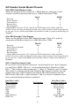
R/F Reader Serial Model Pinouts
F34, DB25 Null Modem Cable
These are the pinouts for Cable F34, a DB25 Female, with pins 2 and 3
crossed, used for connection directly to a DB25 male host COM.
Mod 8
DB25F
Function
Pin
Pin
Frame Ground
1
1
Transmit Data
2
3
Receive Data
3
2
Signal Ground
4
7
*On the DB25 end, pins 4,5,6,8, and 20 are NOT connected in cables sold after
9/15/01. If you are using an older F34 cable and a serial extension cable longer than 80
ft, cut pins 4,5,6,8, and 20 at the DB25 end of the F34 cable to avoid system lockups in
Windows.
F36, DB9 Straight Cable Pinouts
These are the pinouts for the DB9 Female Straight Cable, F36, used for
connection of the Base directly to a DB9 Male host COM.
Mod 8
DB9F
Function
Pin
Pin
Shell (Chassis Ground)
1
Shell
Transmit Data
2
2
Receive Data
3
3
Signal Ground
4
5
* On the DB9 pin end, pins 4,6,7, and 8 are NOT connected in cables sold after
9/15/01. If you are using an older F36 cable and a serial extension cable longer than 80
ft, cut pins 4,6,7, and 8 at the DB9F end of the F36 cable to avoid system lockups in
Windows.
F45-1, Dual Port Serial Cable
If you want to install the Base between a serial terminal and a host computer,
(as with Unix, PICK, VM, etc.), you need the Dual Port Serial Port Cable,
F45-1. This cable has three connectors: 1) Host, 2) Terminal, and 3) Scanner.
This cable is configured so that the Terminal End connects directly into the
female main port of the Terminal; the female Host End connects into the
DB25 male cable end (a cable with pins 2 and 3 crossed is assumed to have
been connected between the host terminal).
Dual Port Cable’s
Host Connector
Frame Ground
Transmit Data
Receive Data
RTS
CTS
DSR
Signal Ground
DTR, CD
Pin Number
1
2
3
4
5
6
7
8,20
8
Dual Port Cable’s
Terminal Connector
Frame Ground
Receive Data
Transmit Data
RTS
CTS
DSR
Signal Ground
CD, DTR
Configuring the Wireless Scanner
for your computer and application
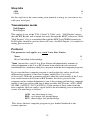
Find the 8 1/2 x 11" laminated Wireless Reader Setup
Menu sheet and look it over. This simple menu lets you
easily configure the Radio/Freedom Reader to work with
almost any computer system, and to tailor its bar code
reading and data format characteristics.
Be sure to read the scanning instructions on the next
page. To read Reader Setup Menu bar codes and
configure your reader, you must know the right way to
scan bar codes.
These are the Wireless Reader's default settings and are shipped configured to
these settings; they can be reset to them at any time by scanning the Start
Setup and Reset codes on the Reader Setup Menu.
Code 39
• Enabled
• Check digit disabled
• Accumulate Mode enabled
• Caps Lock Off
• Start/stop characters not transmitted
2 of 5 Code
• Disabled
• I 2 of 5 Code Disabled
• 6-digit code length
• Check digit disabled
Code 128
• Disabled
• UCC/EAN-128 options disabled
Codabar
• Disabled
• CLSI Format disabled
• Start/stop characters not transmitted
MSI/Plessey
• Disabled
• Check digit(s) not transmitted
Code 93
• Disabled
• Full ASCII disabled
UPC\EAN
• Enabled
• UPC supplements disabled
• UPC-E Compressed / NSC of 0
• UPC-A NSC and EAN-13 1st 2
characters
and check digits transmitted
• UPC-E NSC and EAN-8 1st 2 characters
& check digits not transmitted
General configuration settings
• PC or RS-232 Computer Interface
• Autosense
• CR for Terminator Character
• Data Transmission Timing of None
• Medium Beep pitch
• No preamble or postamble
• No MagStripe Slot Scanner
• USA keyboard
• 9600 Baud Rate, None Parity
• 8 Data Bits, 1 Stop Bit
• Full Duplex Transmission
• For the 2-Way Laser Scanner and Base
Station, ID Character = none
Be certain to turn off any bases with common frequencies before setting
up. If you need to change any of the default settings, or would like to learn
more about the Wireless scanner options, the next several pages will explain,
step by step, how to set them and
9
Laser And Linear Imager CCD Scanning Instructions
Using a laser scanner is basically as simple and intuitive as "point and shoot"
at a distance of 0-24", depending on the density of the bar code. Our Linear
Imager CCD scanners are also "point-and-shoot" and offer “laser-like” scan
distances of 0 – 11 inches from the bar code. The LI101-RF Linear Imager
CCD and the 1-way LZ200 RF Laser both beep only at the Base Station, so if
the Base Station beeps, it got the data. The LZ202 RF 2-way Laser and the
LI102-RF 2-Way Linear Imager CCD both beep at the scanner as well as
the base.
Basically, the Linear Imager CCD and laser scanner's beams must cross every
bar and space on the bar code, without touching any other bar codes, as shown
in the first example below. For both the laser scanners and the Linear Imager
CCD's, you'll need to hold the scanner further away to produce a wider beam
for large bar codes, and closer for bar codes with bars very close together.
Even though momentary exposure to a laser's low-power, visible-light is not
known to be harmful, you should not aim the beam into anyone's eyes.
The important thing to remember about using a laser with the Wireless Reader
Setup Menu is that you need to make sure the scanner's beam covers only one
bar code at a time. The laser scanner's beam is wide enough, and the
configuration bar codes close together enough, that you will need to use your
fingers, or the supplied Laser Setup Assist window, to "block off" bar codes
adjacent to whatever configuration bar code you need to read.
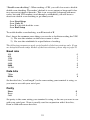
For example, to read
this "5" bar code on the
Setup Menu, you would
need to cover any
adjacent bar codes with
paper or a finger first,
as shown.
10
Don't forget to take the R/F Laser Scanner and the R/F Linear Imager CCD out
of Setup Mode by scanning End Setup, otherwise the batteries will run down
totally because the radio transmitter remains on.
Using The Wireless Setup Menu
1.
To configure your reader using the Reader Setup Menu, you must first
scan the Start Setup code at the top left corner. Do this now. You'll hear
two beeps. During Setup, nothing will be transmitted to your computer;
the Reader Setup Menu codes are strictly for configuring the reader. If you
did not hear two beeps, try scanning the code again, until you hear the two
beeps. If you've never scanned bar codes before, read the scanning
instructions on page 10 before continuing.
2.
Next, choose the topic you want to change an option for, and scan its
code. Let's use Beep Tone, at the lower left corner of the menu, as an
example. Scan the Beep Tone code now. You'll hear two beeps.
3.
Then, choose the option you want to change, from the list next to the topic
bar code you just scanned. For Beep Tone, the options range from 0 for
the lowest pitch to 4 for the highest pitch. Using the "Barpad Table" on
the right side of the Reader Setup Menu, scan the number or letter
associated with the option you have selected. Let's change the beep pitch
to Highest. Now scan the 4 on the "Barpad Table". You will again hear
two beeps. On the 2-Way RF products (Laser and Linear Imager CCD),
the beeps will be in the scanner; on the 1-Way RF products (Laser and
Linear Imager CCD), the beep will be at the Base Station ONLY.
4.
Now scan End Setup (at the top-right corner of the Reader Setup Menu to
complete the setup exercise. You'll hear three beeps, (on the Base Stations
or 2-Way RF products). If you followed the instructions correctly and
successfully changed beep tone to "highest", the three beeps will be higher
in pitch than the other beeps had been. If they aren't higher in pitch, repeat
the steps on this page until you are successful at changing the beep tone.
Now that your beep tone is at the "highest" pitch, you may want to change it
back to "medium" or a different setting. Repeat the steps above, selecting the
option you prefer to "highest" in step 3.
When you've successfully changed the beep pitch, and are ready to configure
the reader for your specific application, scan Start Setup again. Continue
scanning topics and options until you've made all the changes you desire, and
then scan End Setup to complete setup. For keyboard models, pay attention to
Keyboard Country, Computer Interface, and Data Transmission Timing. For
serial models, pay attention to Baud Rate, Parity, and Data Bits. If you are
planning to use several 2-way RF Laser scanners or LI102-RF Linear Imager
CCD scanners with one base station, pay attention to the Set ID parameter.
11
The next several pages will show you all of the various Wireless Reader
options. Default settings are shown in bold in this manual and marked with an
* on the Reader Setup Menu.
Beep Tone
Lowest
Low
Medium
High
Highest
None
0
1
2
3
4
5
Code 3 of 9 (Code 39)
Enable Code 39
Disable Code 39
Enable Full ASCII Code 39
Disable Full ASCII Code 39
Enable Code 39 Accumulate Mode
Disable Code 39 Accumulate Mode
Enable Start/stop character transmission
Disable Start/Stop character transmission
Enable Mod 43 Check Digit
Disable Mod 43 Check Digit
Enable Check Digit Transmission
Disable Check Digit Transmission
Caps Lock ON
Caps Lock OFF
0
1
2
3
4
5
6
7
8
9
A
B
C
D
For information about Code 39 and Full ASCII Code 39, see Appendix C.
See page 28 for information about Accumulate Mode.
Enabling Start/Stop character transmission means that the Radio/Freedom
Reader will transmit the * Start/Stop characters to your computer along with
the data. For example, data of 1234 would be transmitted as *1234*.
Enabling the Mod 43 Check Digit requires the units position of your data to
match the calculation for the check digit explained in Appendix C.
If you've enabled the check digit, enabling Check Digit transmission causes
the reader to transmit it to your computer along with the bar code data.
"Caps Lock ON" means that for all codes lower case letters read as data will
be transmitted as upper case, and upper case as lower. Numbers, punctuation
& control characters are not affected.
"Caps Lock OFF" means that letters will be transmitted exactly as read.
12
Code 128
Disable Code 128
Enable Code 128
Disable UCC/EAN-128
Enable UCC/EAN-128
Enable Storage Tek Tape Label Code
Disable Storage Tek Tape Label Code
Bar Code IDs transmitted
Bar Code IDs not transmitted
0
1
2
3
C
D
E
F
To enable a Bar Code ID character to be transmitted at the beginning of
each bar code read, scan E. The ID’s are as follows:
Codabar
Code 39
UPC-A
EAN-13
a
b
c
d
I2of5
2of5
128
MSI
e
f
g
j
93
UPC-E0
UPC-E1
EAN-8
i
n
o
p
Plessey
LabelCode4
LabelCode5
STK
x
y
z
s
To disable bar code ID characters, scan F. For information about Code 128,
see Appendix F.
UPC/EAN
Enable UPC/EAN
Disable UPC/EAN
Enable UPC/EAN Supplements
Disable UPC/EAN Supplements
st
Enable transmission of UPC-A NSC and EAN-13 1 2
st
Disable transmission of UPC-A NSC and EAN-13 1 1 digits
Enable transmission of UPC-A and EAN–13 Check Digit
Disable transmission of UPC-A and EAN-13 Check Digit
st
Enable transmission of UPC-E NSC and EAN-8 1 Digit
st
Disable transmission of UPC-E NSC and EAN-8 1 Digit
Enable transmission of UPC-E and EAN-8 Check Digit
Disable transmission of UPC-E and EAN-8 check Digit
UPC-E Compressed
UPC=E Expanded
EAN-8 observes 9 & A above
EAN-8 is forced to transmit 8 digits
0
1
2
3
4
5
6
7
8
9
A
B
C
D
E
F
For more information on UPC and EAN, see following page and Appendix H.
Enabling supplements allows you to read 2 and 5-digit supplemental codes
used with magazines and paperbacks. This disallows right-to-left reading of
UPC codes, to assure that the supplement doesn't get skipped.
Use setting 2 to enable reading of the 2 and 5 digit UPC/EAN supplements
commonly found on magazines and paperback books. Use this setting to force
13
left to right reading of UPC codes, assuring that the supplement code is not
missed. This setting also allows for reading of the UCC/EAN 128 Extended
Coupon Code. The Extended Coupon Code consists of a UPC code with a
NSC of 5 or and EAN code with a country code of 99 along with a C0de 128
supplemental code to the right. This setting allows you to read the Code 128
supplement with the UPC/EAN, providing the UPC has a NSC of 5 or the
EAN code has a country code of 99. Without the correct NSC or country code,
the Code 128 portion will be ignored; UPC code with an NSC of 5 or EAN
codes with country code of 99 will not be read unless there is a readable Code
128 supplemental code read also.
UPC-E Compressed Format transmits UPC-E codes as is; Expanded
Format adds zeros to make them the same length as UPC-A.
UPC-E can be used in either normal UPC-E format (implicit NSC of 0) or
UPC-E1 format (NSC of 1). UPC-E1 is enabled by scanning 2 of 5 Code and
8 (9 disables UPC-E1). It is very easy to partially read EAN-13 as UPC-E1, so
don't enable UPC-E1 if reading EAN-13.
If you wish to transmit UPC-A data in EAN-13 format, (an added leading 0
for the USA's country code), scan Terminator Character and F. Scanning E,
the default, sets UPC back to no country code transmitted.
ISBN, International Standard Book Numbering, bar codes are EAN-13 codes
with a 5 digit supplement. If the first three digits are the "Bookland" country
codes of 978 for books or 977 for periodicals, then you can enable
transmission of EAN-13 bar codes in the ISBN format. Suppose you scan an
EAN-13 with 5-digit supplement which is a bar code of
978055337062153495. It would be transmitted in ISBN format as
0553370626. 055337062 are the first nine digits of the ISBN format, and 6 is
the newly calculated Mod-11 check digit.
To enable the transmission of the ISBN format, scan Terminator
Character and D. Scanning C, the default, disables conversion to ISBN
format back to regular EAN-13 format.
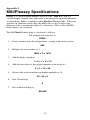
MSI and Plessey
Disable MSI
Enable MSI with 1 Mod 10 check digit
Enable MSI with 2 Mod 10 check digits
Enable MSI with 1 Mod 11 and 1 Mod 10 check digit
Transmit No Check Digits
Transmit 1 Check digit
Transmit 2 Check digits
Enable Plessey (mutually exclusive with MSI)
Enable LabelCode5
Enable LabelCode4
For more information about MSI code, see Appendix I.
14
0
1
2
3
4
5
6
7
8
9
Codabar
Enable Codabar
Disable Codabar
Enable CLSI Codabar
Disable CLSI Codaber
Enable Start/Stop Character Transmission
Disable Start/Stop Character Transmission
0
1
2
3
4
5
For information about Codabar, see Appendix E.
CLSI format is a form of Codabar often used by libraries.
Enabling Start/Stop character transmission means that the R/F Reader will
transmit start/stop characters to your computer along with data. If you're varying
start/stop characters with different label types, you'll want to enable
transmission.
2 of 5 Code
Enable Interleaved 2 of 5
Disable Interleaved 2 of 5
Enable Interleaved 2 of 5 Check Digit
Disable Interleaved 2 of 5 Check Digit
Enable Check Digit Transmission
Disable Check Digit Transmission
Enable Standard 2 of 5
Disable Standard 2 of 5
0
1
2
3
4
5
6
7
For information about Interleaved and Standard 2 of 5, see Appendix G.
Enabling the Check Digit requires the data's units position to match the
calculation for the check digit explained in Appendix F. If you've enabled the
check digit, enabling Check Digit transmission causes the reader to transmit it
to your computer along with the bar code data.
2 of 5 Data Length
2 of 5 Code is so susceptible to interpreting partial scans as valid reads
that the Radio/Freedom Reader uses fixed-length data as a safeguard. To
choose a data length, scan it as a two-digit number using the Barpad Table.
For example, to select 8-digit data length, you would scan a 0 and then an 8.
Because Interleaved 2 of 5 is required to be an even number of digits in
length, you must use an even number. If you're unsure of your bar code
length, temporarily set the length to 00, read a bar code, and count its digits
and then set it to the actual length. DO NOT PERMANENTLY SET THE 2
of 5 LENGTH TO 00 or you will get misreads!
15
Code 93
Enable Code 93
Disable Code 93
Enable Full ASCII Code 93
Disable Full ASCII Code 93
0
1
2
3
For more information on Code 93 see Appendix D.
Data Transmission Timing
None
Short
Short Medium
Medium
Long
0
1
2
3
4
This setting does not apply to the Mac or to any USB attachment. Try the
Learned Timing before trying these timing settings. There are five different data
transmission rates. Most computers work perfectly at the fastest speed ("None"),
but some systems require slower rates. Set your Radio/Freedom Reader to the
"None" setting, and (when you're done configuring it) try reading some codes.
In the unlikely event that you get partial or garbled reads, See the Learned
Timing under Computer Interface, or you can use trial and error with the
timings.
Don't assume that if you try the slowest settings that one of the other ones
won't work. It is not unusual to find only one setting that will work. Before
trying each timing setting, be sure you have not sent the BIOS off into space
with incorrectly timed data, resulting in a keyboard lock-up; if you get a
keyboard lock-up, you will have to reboot the computer before trying another
delay setting. (Once the keyboard is locked up, even correctly timed data will
not transmit until you have rebooted.)
Terminator characters
Enter (carriage return)
None
HT
CR/LF
0
1
2
3
Depending on your application, you may wish your Wireless Reader to
transmit bar code data to your computer with an Enter (carriage return), a Tab
at the end, or with no extra terminating character at all.
If you need a terminator character other than CR or HT or CR/LF, you can
get it by specifying None here and then selecting your desired terminator
character(s) specified in the Postamble (See Page 18).
16
Computer Interface
PC Keyboards and USB Attachment
PC Keyboard Learned Timing
Macintosh ADB Keyboards
1
8
A
Scan the number on the Barpad Table corresponding to the type of system you
are using. All PC compatibles and computers using a USB (Wedge Saver)
attachment use setting 1.
PC Keyboard Learned timing does not apply to the Mac or to USB only
computers. The Learned Timing can learn your keyboard timing and save it.
Scan Start Setup, Computer Interface, 8, and then press a key on the computer
keyboard (the reader beeps once – if it doesn’t beep, it didn’t capture the timing
and you will have to use “Data Transmission Timing”). Now scan End Setup
and the timing should be captured by the Base Station into the EEPROM.
If you experience trouble, try the “PC Keyboard Learned Timing" setting of 8;
as a last resort, try the Data Transmission Timing settings, (not applicable to
Mac or USB).
Serial Reader mode settings:
RS-232 ASCII Data Format
RS-232 “PC-Terminal Mode” Data Format
RS-422 ASCII Data Format
3
4
5
RS-232 ASCII is used for almost all serial ports and terminals.
"PC-Terminal Mode" refers to the very rare Concurrent DOS.
RS-422 applies to the RF Bases and is used with RS-422 boards only.
Preamble
A "Preamble" is a user-specified data string transmitted at the beginning of
each bar code. For example, if you specify the preamble @@ and read data of
123456, "@@123456" would be transmitted to your computer. With the 2Way LZ2x2-RF Laser, the Preamble applies to the scanner, not the base
station because there may be multiple scanners per base.
The default is no preamble. To select a preamble, scan up to 15 characters from
the "FULL ASCII MENU" on the back of the Reader Setup Menu, and then scan
SET when you're done. To return to the no preamble setting, scan Clear here
instead of scanning SET or any characters from the FULL ASCII MENU.
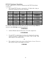
You can trim 1-15 leading characters from bar code codes by scanning a ~
(tilde -- ASCII 126) followed by a single digit, 1 through F, as part of the
Preamble. (Bar codes that are shorter than the amount-to-trim are transmitted
17
with no trimming.) Consider the examples in the following table to
understand how trimming works:
Bar Code Data
123
12345678
12345678
12345
123456
Preamble
XYZ
~3XYZ
~9
~A
~5
Data Transmitted
XYZ123
XYZ45678
12345678
12345
6
You can also trim selectively by bar code type. For example, you can trim 2
characters from Code 39 and a different amount from other bar code outputs. This
is done by using the bar code ID character in conjunction with the tilde (~). A
preamble of ~b2~c1 says trim 2 characters from the front of Code 39 output and
trim 1 character from the front of UPC-A. Refer to the Code 128 parameter on
page 13 for a list of the ID character associated with each bar code type.
A final use of the Preamble/Postamble is to enter a minimum/maximum length
check for bar code data read. Use the Preamble or Postamble by entering
|nnmm where "|" is ASCII 124, "nn" is the two digit minimum to be read and
"mm" is the two digit maximum to be read.
Postamble
"Postamble" refers to a user-specified data string transmitted at the end of each
bar code. For instance, if you specify the postamble @@ and read data of
123456, "123456@@" would be transmitted to your computer.
The default is no postamble. To select a postamble, scan up to 15 characters
from the "FULL ASCII MENU" on the back of the Reader Setup Menu, and
then scan SET when you're done. To return to the no postamble setting, scan
CLEAR here instead of scanning SET or any characters from the FULL
ASCII MENU.
You can trim 1-15 trailing characters from bar code codes by scanning a ~ (tilde
-- ASCII 126) followed by a single hex digit, 1 through F. (Bar codes which are
shorter than the amount-to-trim are transmitted without trimming.) Consider the
examples in the following table to understand the options of the Postamble:
Bar Code Data
123
12345678
12345678
12345
123456
Postamble
XYZ
~3XYZ
~9
~A
~5
Data Transmitted
123XYZ
12345XYZ
12345678
12345
1
Bar codes that are shorter than the sum of the Postamble trimming and
Preamble trimming will be transmitted without trimming. Selective trimming
18
and min/max bar code data is also supported through Postamble specifications,
(See Preamble above for complete details).
Characters
This setup option allows you to output ASCII characters different from the
ones scanned. (Don't use this option to configure the Radio/Freedom Reader
for your non-US keyboard -- instead, use the Keyboard Country option
described below.)
For example: Suppose you want the Radio/Freedom Reader to output a hex
92 character every time you scan a 1 (hex 31); you want to remap hex 31 to
hex 92, (If you're using 8 data bits, output of 80-F8 codes is possible.)
1) Scan the Start Setup Bar Code
2) Scan the Characters Bar Code on the Setup Sheet.
3) Scan 3 1 and 9 2 to output hex 92 when reading a "1".
4) Scan up to 7 other pairs of character reassignments.
5) Scan Set when complete.
6) Scan End Setup to exit setup mode.
Hex values for each character code are shown on the Full ASCII Menu, (the
back of Wireless Setup Menu). The equivalent decimal values are also shown
for each character.
You can also eliminate characters by reassigning hex codes to FF. For
example, to strip all $ (dollar sign) characters from transmission, you would
follow the above instructions and scan 2 4 F F in step 3.
Keyboard country
This option configures the Radio/Freedom Reader for your choice of 15
keyboard country settings, such as USA (the default), UK, French, German, etc.
Scan the keyboard country bar code and then the two-digit code for your
keyboard country (listed on the Reader Setup Menu), such as 14 for UK.
Set ID Character
(This parameter only applies to the 2-Way RF Laser and the LI102-RF 2-Way
Linear Imager CCD.)
There are actually two IDs that can be set on each scanner. 1-8 to identify
which multiple laser is communicating with a base station, and a-z to associate
groups of scanners with bases operating on the same frequency.
Multiple scanners on one base station require each scanner to be set to a
unique ID of 1,2,3.....8. Scan Set ID Character and then scan 1-8 for each
scanner, giving each a different ID of 1-8.
It is possible to have more than 4 base stations, one for each available
frequency (3 in Europe) operating in the same room; common ID characters
19
between a scanner and a base station make it possible for a group of associated
scanners/base to ignore other groups of units with different IDs on the same
frequency. This is not recommended, but where separation is the rule and
overlap is the occasional exception, this grouping ID becomes practical.
Because there is "collision detect and retry" logic built into every two- way RF
scanner and two-way Base Station, units can share the same frequency and
still operate, providing the transaction volume is not so high that collisions and
retries slow down the response time. Use a-z to make the associations. Scan
Set ID Character and the scan a-z for every scanner in the group. Be sure all
other base stations on the same frequency are turned off when making these
groupings. You will need to label the scanners by groups.
Be sure that all base stations in the same room on the sharing the same
frequency as the group you are assigning are powered off, otherwise all
common frequency bases will be set to the same ID character, (which you
don't want to do).
Link Test Code
This is a code to test the transmission link between the Wireless Scanner and
its Base Station, without transmitting data. You can use this to be sure you are
in range and able to hear the base station beeping. No data is transmitted. Do
not enter the Setup Mode when performing the link test. This code is the
same as the "Clear Buffer" code on the Barpad Menu.
Reset
Once you are in the Setup Mode, don't scan Reset unless you're sure you want
to restore the Wireless Reader to its default settings (as described on page 9),
erasing all changes you've made.
DIFFICULT CODE SETUP OPTIONS
Aiming Laser Dot: Sometimes it is difficult to see the laser beam and know
you are on the bar code, especially if you are attempting to read outdoors in
direct sunlight. The laser can be outputted as a brighter dot for a few seconds,
allowing the user to place the dot in the middle of the bar code; then the laser
beam starts sweeping for the read. As shipped, the laser beam never forms an
aiming dot, but you can program a number of seconds that you wish the
aiming dot to appear before the sweeping beam by scanning the following:
Scan Start Setup
Scan Protocol
Scan 3 to select a 1 second aiming dot, or
4 to select a 2 second aiming dot, or
5 to select a 3 second aiming dot, or
6 to select a 4 second aiming dot, or
7 to select a 5 second aiming dot, or
2, the default, to eliminate an aiming dot.
Scan End Setup
20
4-second beam: Another option with problem reading conditions is to increase
the length of the time the scanner attempts to read, from the default 2-second
beam to a 4-second beam. To select the 4-second beam:
Scan Start Setup
Scan 2 of 5
Scan F to select the 4-second beam
Scan End Setup
To return to the default 2-second beam, scan E instead of F.
Automobile VIN READING:
There is special support for reading automobile Vehicle Identification Numbers,
VIN, remotely from the computer. (CCDs will not read through a windshield,
only laser scanners.) You may want to use the aiming dot above too.
"Delayed Transmission": is a 2-way scanner feature which allows the user to
leave the computer, (perhaps being operated by someone else), go to the
location of the car, scan the VIN with the first trigger pull, return to the
computer, be certain that the screen and cursor are properly positioned, and
then pull the trigger again for transmission. The first trigger pull scans and
stores the bar code. The second trigger pull transmits the data, permitting the
user to be sure the cursor is properly positioned. To change the reader to
“Delayed Transmission”:
Scan Start Setup
Scan Terminator
Scan B to select "delayed transmission"
Scan End Setup
To disable "delayed transmission", repeat the above substituting A for B.
"Difficult Code 39 Reading": This 2-Way scanner feature facilitates reading
of he VIN number on automobiles, which is often a difficult-to-read bar code,
especially reading through a windshield. VIN numbers are long, often
weathered, often dirty, and challenging to read.
To enable the more aggressive Code 39 algorithms necessary to read
windshield VINs:
Scan Start Setup
Scan 2 of 5 Code
Scan D for windshield reading
Scan End Setup
To return to the default Code 39 decode algorithms, scan B instead of D.
21
"Double-scan checking": When reading a VIN, you will also want to disable
double scan checking. The reader’s default is to not output or beep until it has
two successive identical decodes. This is an acceptable safeguard with most
codes, but with VIN numbers read through a windshield, you will have to
deactivate double scan checking to get timely reads.
Scan Start Setup
Scan Code 39
Scan F to disable doubles scans.
Scan End Setup
To enable double scan checking, scan E instead of F.
Don’ forget the common sense things you can do to facilitate reading the VIN:
1) Be sure the window on the laser scanner is clean.
2) Be sure the windshield is wiped before of reading.
The following parameters apply serial models of the base stations only. If you
are using keyboard wedge models of the base stations, please skip to page 25.
Baud rate
300
600
1200
2400
4800
9600
19,200
0
1
2
3
4
5
6
Data bits
7 Bits
8 Bits
0
1
Set the data bits ("word length") to the same setting your terminal is using, or
you want to use with your serial port.
Parity
None
Even
Odd
0
1
2
Set parity to the same setting your terminal is using, or the one you want to use
with your serial port. None is usually used in conjunction with 8 data bits,
Even or Odd with seven data bits.
22
Stop bits
1 Bit
2 Bits
0
1
Set the stop bits to the same setting your terminal is using, or you want to use
with your serial port.
Transmission mode
Full Duplex
Half Duplex
0
1
This applies to use of the "F45-1 Serial Y Cable" only. "Full Duplex" means
that the R/F Reader will transmit data only through the HOST connector. With
"Half Duplex", data is transmitted through the HOST and TERM connectors.
Full Duplex should be used in almost all cases, but Half Duplex. 0 is useful for
testing pin-out reversal.
Protocol
This parameter only applies to a serial 2-way Base Station.
None
Host Controlled Acknowledge
0
1
"None" means that a serial 2-way Base Station will immediately transmit an
acknowledgement to the 2-way RF Scanner from which it has just received
transmitted data, (without waiting for a response from the host computer program.)
If you want the host computer program to analyze the data and to send back
different beep patterns to the laser scanner, enable Host Controlled
Acknowledge. With this parameter enabled, when the serial models of the 2-way
base station receives data from an R/F Scanner, the data is passed to the
computer and no acknowledgement is sent to the scanner until the host computer
replies to the base station with one of three possible ASCII codes: ACK (ASCII
06), BEL (ASCII 07), DC2 (ASCII 18). Upon receipt of these codes from the
host computer, the base sends a signal back to the transmitting laser scanner that
causes it to emit beeps as follows:
ACK - one short beep in laser
BEL - two longer low pitched beeps
DC2 - three longer low pitched beeps
This allows the host computer program to give limited feedback to the
scanner operator.
23
Please refer to Host Response Delay to determine if you need to compensate
for slow host program response by slowing down the retry time when failing
to get a response from the base station.
Host Response Delay
(This parameter only applies to serial 2-way Base Stations - B58/B59 with Host
controlled acknowledge enabled.)
If you have a serial 2-way Base Station with Host controlled acknowledge
enabled under Protocol, and your host computer program is slower in
responding than 1/2 second, in order to reduce retry radio traffic, you need to
specify a new delay time. This parameter needs to be set for each 2-way laser
scanner used. Specify in 1/10 seconds of 01 (.1 secs) to 99 (9.9 secs).
Suppose you are running a Unix application that takes 1 second from receipt
of data to respond: specifying 10 will add one second to the retry delay,
thereby increasing the listening time before retrying. This is particularly
important when operating multiple scanners on one base station, but it is also
helpful with only one scanner. Even with one scanner, the acknowledgement
can collide with a retry without sufficient delay.
With normal Windows and DOS applications, the host response is so fast, it is
not necessary to change this parameter. However, if you have a very
complicated program that must access multiple databases for each data item
transmitted, you may need to specify additional delay.
Test the Reader with your computer
If you are connected by keyboard interface, or if you have a serial reader and
are using PortKey with an IBM compatible, you should be able to scan the bar
code on the next page, hear a beep (2 beeps on 2-way laser), and see data
displayed on the computer's screen. First get your computer to some program
where you can type and see it on the screen, (i.e. Notepad). Now scan the
TEST LABEL on the following page. Your screen should show:
TEST LABEL
If you can't read the TEST LABEL, see the Scanning Techniques back on page
10. If you don't get a beep, try moving closer to the Base Station and moving
the scanner closer or farther away from the bar code. If you get a beep (two
beeps with 2-way laser scanner), but no data displayed:
1.
Be sure your Computer Interface is set correctly,
2.
Try the Learned Timing computer interface settings as detailed in the
Installation and Setup section of this manual.
If you still have trouble, see the Troubleshooting section of this manual.
If you are connected to serial port and aren't using PortKey, you will need to
use a communications program; or use the WDR Serial Test Program
24
distributed on the diskette enclosed with your serial reader. The program is for
Windows only.
If you are using the WDR Serial Test Program, follow these guidelines:
•
Make sure the serial parameters on your Base Station match those
used by your computer.
•
Make sure you are connected to a valid serial port.
If you still are having problems, see the Troubleshooting Section.
25
Radio Considerations
Be sure you have a frequency matched Base Station and R/F Scanner. The
color of the label on the underside of the R/F Base Station should match the
color on the scanner antenna or ID label, ((black/black, yellow/yellow,
purple/purple, red/red, etc).
RF Short range problems: 1) elevate the Base Station to as high as possible; 2)
move serial Base Stations to different parts of the room; 3) try placing the base
station on a metal file cabinet; 4) change keyboard wedge units to serial and try
locating away from the computer; 5) by process of elimination, turn off different
electronic equipment in the area to see what is causing the interference, (maybe
by relocating the offending equipment, the range problem will go away).
One-Way Operating Considerations
When scanning with the one-way products (LI101-RF Linear Imager CCD and
the LZ200-RF Laser), the radio link is one-way from the R/F Scanner to the
R/F Base Station. The Base station has the beeper in it; the one-way scanners
have no beeper in them, (there is a beeper in the 2-way RF Laser, but not in its
base). Therefore, if you are out of hearing range of the one-way base station's
beeper, you cannot know if scanned data was successfully transmitted to the
computer or if the scanned data was not successfully decoded and therefore
not transmitted. The big mistake you must avoid is UNKNOWN
DUPLICATE DATA ENTRY -- unknowingly reading multiple times
successfully because you are out of hearing range and have assumed that your
scans were "no-reads". Staying in hearing range of the base station will
prevent the problem. The same problem could occur with a corded scanner,
but because cords are normally 6-10 feet in length, out of hearing range has
never been a matter of concern before.
Use of a louder speaker (in lieu of the beeper) can extend the range. A speaker
jack is standard on the R/F Base Station so that you can attach a inexpensive
powered speaker such as available from Radio Shack (catalog # 40-167 at
$19.95 -- or you could attach a wireless headphone or amplified earphone for
beeper confirmation. In the USA, this product is available for $80 from Sears,
Fry's, or a multitude of stereo sound outlets - the brand name is Recoton W200.
26
2-Way Laser Operating Instructions
Operational Details
The two-way LZ202-RF Laser Scanner and LI102-RF Linear Imager CCD:
1.
chirps on a "good read" or successful scan while turning off the scanner
beam, and
2.
beeps loudly when it gets the acknowledgement back from the Base
Station that it has received the data.
The yellow light on the back of the scanner indicates that it is transmitting.
You will see up to four transmission attempts before the unit goes to sleep and
waits for you to pull the trigger again. The green light indicates that it has
received the acknowledgement from the Base Station. After four unsuccessful
tries of transmitting to the base without an acknowledgement, the scanner
chirps 8 times and goes to sleep waiting on the operator to move closer to the
base station and pull the trigger again for a transmission retry. After going to
sleep on an unsuccessful read, when the trigger is pulled again, the scanner
beam doesn't turn on for reading; instead, the unit beeps three times to indicate
is re-transmitting and just transmits again. This sleep and retransmission cycle
is repeated until the acknowledgement is received or the buffer is deliberately
cleared. In this way, no scanned data is lost, even though you have wandered
out of range of the Base Station. Until the pending data acknowledgment has
been received, pulling the trigger will only retransmit and not activate the
scanning laser beam for additional reading.
If you are out of range and want to clear data in the scanner's buffer waiting to
be transmitted again, by pulling the trigger and holding it down for 15 seconds,
the buffer will be cleared and the scanner will emit 3 low pitched beeps.
Multiple Scanners on one 2- Way Base Station
Multiple 2-way scanners can talk to one base station on the same frequency by
scanning a unique ID Character in each scanner. Just scan Start Setup, Set ID
Character, and the 1-8 followed by End Setup for each scanner, (using a
different value 1-8 for each scanner). Remember though, the scanning
throughput is dependent on the total volume of scanning from all scanners
assigned to the same frequency sharing a base station. If two scanners transmit
at the same time, the base station will receive neither of the messages and both
scanners will wait for a random time and retransmit. The random wait before
retransmission assures maximum probability of both getting through. If there
are too many collisions in radio transmission, the scanning rate will be slow.
The fix is to buy more base stations of a different frequency and get a portion
of the scanners changed to the frequency of the additional base station.
27
Multiple 2-Way Base Stations on the Same Frequency.
Although not recommended, you can have more than one two-way base station
on the same frequency operating in a common area, but you must set each
grouping of assigned scanner(s) with the ID of the Base Station. All other Base
Stations with a common frequency must be turned off during the setup of
another base and/or associated laser scanners. Otherwise, all base stations that
can hear will be set to the same ID Character and its purpose will be defeated.
Base Station IDs are a-z and Scanner IDs are 1-8.
This is not recommended because of interference. However, occasionally,
there will be need for more base stations than the number of available
frequencies. Providing that you keep the overlap to the fringes of coverage,
this feature makes it impossible for two base stations on the same frequency to
receive the same data.
28
Accumulate Mode
Accumulate Mode is an option (which can be enabled or disabled using the
Reader Setup Menu's Code 39 section) allowing the reader to accumulate
multiple bar codes in its buffer, then transmit them to the computer as if they
had been a single bar code. This is useful for entering quantities and other
variable data. A small laminated barpad card is provided with each reader
ordered to aid in entering variable quantities.
It works with Code 39 only, and can't be used with a check digit. When the
reader reads a bar code with a leading space, it beeps and buffers the data
without transmission. It continues to read and buffer bar codes (up to 40
characters) until it reads a bar code without a leading space. Then the entire
buffer (including that last code) is transmitted as one long bar code. A bar
code of a double minus (--) sign clears the buffer. Scanning a backspace code
($H) backspaces in Full ASCII mode. A handy code for Enter (as seen on the
"Barpad" below) is a Start/Stop only. (No data.) The code to use for testing the
transmission link between the R/F Scanner and the R/F Base Station is the
CLEAR BUFFER code (the same bar code as titled Link Test on the Setup
Menu. It will cause beeps to be heard, but no data will be transmitted to the
computer -- testing blind with no computer consequence.
This numeric "Barpad" illustrates Accumulate Mode. Scan 5, 3, 8, and Enter.
The reader transmits a single message of 538.
7
8
9
4
5
6
1
2
3
0
Clear Buffer
29
Enter
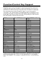
Function/Control Key Support
The RF Scanner can also transmit key sequences for function, control, alt
(command and option keys on Macs), cursor and shift keys, for ease of use
with the many software packages using these keys for menus or commands.
You can include these codes in other bar codes, or you can scan these
“keystrokes” into your Preamble or Postamble in order to add them to every
scan from your reader. You must have Full ASCII Code 39 enabled on your
reader (this is the default setting). Scan the corresponding bar code from the
Full ASCII menu to emulate the chosen key.
PC Key
Mac ADB Keyboard
Full ASCII Menu Bar
Code
F1
F1
SOH (f1)
F2
F2
STX (f2)
F3
F3
ETX (f3)
F4
F4
EOT (f4)
F5
F5
ENQ (f5)
F6
F6
ACK (f6)
F7
F7
BEL (f7)
F8
F8
SO (f8)
Numpad 5*
Enter
LF
Enter
Return
CR
F9
F9
SI (f9)
F10
Cmnd On
DLE (f10)
Del
Del
DC1 (Del)
Insert
Cmnd Off
DC2 (Ins)
Left Arrow*
Left Arrow
DC3 ( )
Rt Arrow*
Rt Arrow
DC4 ()
Dn Arrow*
Dn Arrow
NAK ()
Up Arrow*
Up Arrow
SYN ( )
Pg Up*
Pg Up
VT (Pg Up)
Pg Dn*
Pg Down
FF (Pg Dn)
Home*
Home
ETB (Home)
End*
End
CAN (End)
Shift ON
Shift ON
EM (Shift ON)
Shift OFF
Shift OFF
SUB (Shift OFF)
Control On
Control On
FS (Ctrl ON)
Control Off
Control Off
GS (Ctrl OFF)
Alt On
Option On
RS (Alt ON)
Alt Off
Option Off
US (Alt OFF)
* refers to the keys on the Number pad on the far right side of a PC keyboard.
To emulate any of the keys above, scan the appropriate bar code from the
FULL ASCII MENU. For example, to emulate the f5 key, scan the ENQ bar
code.
30
Function keys F1 through F10, and numeric-pad keys (such as Left Arrow and
Del), are encoded by a single control character as shown in the table above.
Simply scan the correct bar code from the FULL ASCII MENU. For example,
if the WDP reads the bar code SOH (ASCII 001 -- a control-A) from the
FULL ASCII MENU, it will transmit an F1 key.
Shift, Ctrl and Alt keys require three sequences:
1) The ON code generated when the Shift, Ctrl or Alt key is pressed.
2) The other key to be used in conjunction with the Shift, Ctrl or Alt
key.
3) OFF code generated when the Shift, Ctrl or Alt key is released.
(For example, to create a Control C bar code: use Control ON, C, and Control
OFF. To put Control C in a Preamble or Postamble, scan from the Full ASCII
Menu: Control ON, C, and Control OFF).
Center Control Keys
The Center Control Keys in the keyboard have to be used for a Mac with USB
for control keys. If you scan bar codes mapped to the control keys on the far
right of the keyboard, you will get numbers because the Mac USB keyboard is
always in Num Lock. On other keyboards, if you want your application to be
immune to the setting of the Num Lock key, use the bar codes mapped to the
Center Control Keys instead of the keys on the Full ASCII menu.
The below chart corresponds to the small center section of keys between the
main letter keys and the Numeric keypad on the far right of the keyboard and
requires you to scan two bar codes from the FULL ASCII MENU - the NULL
bar code and then the appropriate character. For example, to emulate the END
key, scan the NULL bar code, then the 1 bar code.
PC Key
Mac USB Key
Insert
Delete
End
Down Arrow
Page Down
Left Arrow
Line Feed
Right Arrow
Home
Up Arrow
Page Up
Windows ON
Windows OFF
ENTER (num)
Ins
del
end
down arrow
page down
left arrow
Line Feed
right arrow
home
up arrow
page up
Command ON
Command OFF
ENTER (num)
31
Full ASCII Menu Bar
Codes
NUL 0
NUL . (period)
NUL 1
NUL 2
NUL 3
NUL 4
NUL 5
NUL 6
NUL 7
NUL 8
NUL 9
NUL C
NUL D
NUL E
Function keys F11 and F12
Function keys F11 and F12 require two bar codes to be scanned to make these
functions keys. The F11 key is created by combining the Null and SOH. The
F12 key is created by combining the Null and the STX.
Windows Key
The Windows key on a Windows keyboard is transmitted by scanning 4 bar
codes - NULL and C for Windows On (pressing down) and NULL and D for
Windows Off (releasing the key).
Command and Option Keys on Mac USB Keyboards
When you have a WDP Reader attached to a Macintosh Computer's USB port,
to emulate the Command key, use the Windows key ON/OFF bar codes
NULL, C (Command ON) and NULL, D (Command OFF) For the Option Key
ON/OFF use RS (Option On) and US (Option Off).
If you have an older Worth Data Reader (before 6/99), you can also imitate the
Command Key by key codes in the Preamble/Postamble. To transmit
Command N would be:`E01F'N`E0F01F'
Transmitting any ASCII character using its 3-digit ASCII code
You can also transmit any ASCII character from 000 to 255 by emulating the
PC technique of typing a character's ASCII number on the numeric pad while
holding down the Alt key. For example, to transmit ASCII 250, you would
scan the bar codes for:
Keystroke
Alt ON
Ins (0 on the numeric pad)
Down Arrow (2 on the numeric pad)
Numpad 5
Ins (0 on the numeric pad
Alt OFF
32
Full ASCII Menu
Bar Code
RS
DC2
NAK
LF
DC2
US
Troubleshooting
All Models Troubleshooting
The beam won’t stay on, or I just get a narrow beam when I pull the
trigger, or The scanner won’t turn on when I pull the trigger and I get 3
beeps
• All of the above problems are an indication that your BATTERIES
ARE TOO LOW. With any of the above symptoms, change to known
good batteries before assuming you have some other kind of problem.
Also, make sure the batteries are inserted CORRECTLY – batteries
won’t work if they are not inserted in the right direction. See page 51
concerning changing batteries and the correct battery orientation.
The reader won't beep when reading bar codes
• Recheck all the connections. Get close to the Base Station. Try reading
the Link Test bar code, following the steps for scanning on pages 10-11.
•
If you hear two beeps, but see nothing on the screen, and you are
reading the pocket card, you must read the ENTER bar code to have
anything transmitted. Any Code 39 or 128 bar code with leading spaces
(such as the Barpad on page 28) will not be transmitted to your
computer until you read a bar code without a leading space. Try
reading the Test Label on page 25 as an example of a known good label
without a leading space. If you have bar codes with leading spaces in
them, and you want them transmitted, you must disable Accumulate
Mode using the Setup Menu.
•
Reread the configuration section and make sure you properly enabled
the bar code types you're trying to read.
Extra characters at the beginning or end of your bar code data
• Clear the Preamble and Postamble.
Poor read rate
• Get close to the Base Station and try reading the test label on page 25
(following the scanning instructions on pages 10-11) as an example of a
known good bar code. Examine your bar codes to make sure they have
dark bars, clearly defined bars and white spaces, and a "quiet zone" of
at least 1/4 inch to the left and right. If the bars are gray, or so dark that
they "bleed" into the white spaces, the person or organization printing
them will need to adjust the printer or get a new ribbon or toner
cartridge for it.
I get six beeps when the One-Way Base Station powers up or six flashes
on the 2-way Base Station.
• The unit needs repair. Call for an RMA.
33
The Decode Green Light on LZ200-RF One-Way Laser or LI101-RF
Linear Imager CCD stays lit.
• On One-Way units, the batteries will run down real fast too. This means
that you are still in Setup Mode. Scan End Setup to turn the light out.
The Orange light stays on the LZ202-RF 2-way RF Laser Scanner and
LI102-RF Linear Imager Scanner.
• You are in Setup Mode. Scan End Setup on the Wireless Setup Menu.
Wedge Troubleshooting
A one-way base station installed in Wedge mode doesn't beep three times
when you power up your system; or a 2-way base doesn't go from red to
green on the front LED; or the keyboard locks up; or you get a "keyboard
error" or "301" message.
• Check the cable connections to make sure everything is plugged in
securely. 6 pin mini-din keyboard connectors can sometimes be tricky - make sure they're plugged in as far as they can go. Make sure you
plug the Y-cable into the keyboard port rather than the mouse port.
•
If, after checking the connections, you still have a problem, your PC and
keyboard combination probably doesn't have enough leftover power to
drive the bar code reader also. Don't use any old 5V power supply; it
must be regulated and must be the right polarity, otherwise you will
damage the Base Station. Order a 5-volt external power supply (feature
code F10 or 110V, F11 for Euro 220, and F14 for the UK).
The reader transmits incorrect data to the screen
• Reread page 17 and make sure you chose the proper Computer Interface.
•
If part of the data is correct and part missing, first try the PC Keyboard
“Learned Timing”. If that doesn't work, you will have to tell the R/F
Reader to transmit data at a slower rate, by changing Data
Transmission Timing. Read page 16 on Data Transmission Timing.
•
If the reader is transmitting punctuation characters (!@#$%^&*) when
reading numeric bar codes, or transmitting letters in the wrong
(upper/lower) case, you may have a Num Lock, Caps Lock, shift or
timing problem. Check your keyboard to see if the Num Lock or Caps
Lock keys have been activated. If you have a PC, try the Learned
Timing setting. Finally, try Data Transmission Timing (See page 16).
Timings are fixed for Mac; no need to try to change.
•
If you're using Code 39, read page 13 to see if you've set Caps Lock
properly for your application. If your Code 39 bar codes include
punctuation characters %, $, / or + which don't up in the output, the
reader is seeing them as part of Full-ASCII Code 39 sequences. Using
the Reader Setup Menu, disable Full ASCII Code 39.
34
Serial Troubleshooting
The reader beeps on reads, but nothing appears on your screen using
PortKey OR nothing appears to your own software.
• Recheck the installation instructions beginning on page 2 to make sure
all cables are properly connected.
•
If you're trying to read Code 39 bar codes with leading spaces (such as
the Barpad on page 28) and have enabled Accumulate Mode, those bar
codes will not be transmitted to your computer until you read a bar
code without a leading space. Try reading the Test Label on page 25 as
an example of a known good label.
•
If you're using PortKey on an IBM-compatible, verify (1) that you set
the reader to the same settings as the DOS MODE command (baud rate,
data bits, stop bits, and parity); and (2) that you ran PortKey with the
correct serial port as a parameter (i.e.: Portkey Com1).
•
If you're using your own software to read the serial port, verify that the
problem is not in your software. Run the WDR Serial Test Program
that shipped with your reader and see if it gets any data on the screen
when you read a bar code.
•
Use a "null modem" connector to test switching pins 2 and 3 on one or
more serial cables, or use a breakout box to modify your cable(s).
The reader doesn't beep when you try to read your bar codes.
• Make sure the power adapter is plugged in.
•
Try reading a known good bar code -- the test label on page 25,
following the steps for proper scanning technique on page 11.
•
Read the instructions beginning on page 9 on configuring the Reader
for different bar code types and formats, and make sure you properly
enabled the bar code types you're trying to read.
Data characters are garbled or missing.
• Make sure you've set the reader to the same baud rate, parity, data bits
and stop bits as your serial port.
•
If Code 39 bar codes are transmitting in the wrong case (upper and
lower transposed), set Caps Lock Off on the Setup Menu.
•
If you're getting occasional extraneous characters, try cutting the
jumper between pins 8/20 in the serial Y-Cable's DB25 connectors. See
page 8.
35
My system locks up or I get Windows General Protection Faults when
using my serial RF Reader on a PC running Windows.
• This is an interference problem and occurs if you are using a serial
extension cable over 80 feet long in combination with our F36 9-pin
serial cable or F34 25-pin serial cable shipped before 9/15/01, or you
have built your own cable (over 80 ft) and are not using our F36 or F34
cable.
All F36 9 pin serial cables shipped after 9/15/01 have pins 4,6,7, and 8
cut at the DB 9 end of the cable. If you have one of the older cables or
have built your own, you need to cut pins 4,6,7, and 8 at the 9-pin end
of the cable; see page 8 for details on which pins should remain
connected.
All F34 25 pin serial cables shipped after 9/15/01 have pins 4,5,6,8,and
20 cut at the DB25 end of the cable. If you have one of the older cables
or have built your own, you need to cut pins 4,5,6,8, and 20 at the 25pin end of the cable; see page 8 for details on which pins should remain
connected.
36
Appendix A
Opening the Base Case
Use the illustrations below as a guide while removing the Base's circuit board
from its case.
Turn your Base unit upside-down and unscrew its single Phillips screw. If you
don't completely remove the screw you can use it as a lever to pull up on the
cover, otherwise insert a fingernail, credit card edge or small screwdriver
blade into the gap between the base and side of the case. Gently use it as a
lever to lift up the edge of the base, then grasp the edge of the base and open it
outward like a door.
This exposes the reader's circuit board, as shown below. Next you will need to
remove the shiny metal shield to expose the jumpers. Use the same flat head
screwdriver to lift up the top of the metal can. Now you can see the jumpers
and the EPROM.
When you've finished examining or changing jumper settings, put the reader
case back together by reversing the steps illustrated on this page.
37
Appendix B
Jumper Settings
Your RF Base is shipped with P2 set as either keyboard or serial, depending
on what you ordered.
Why might you need/want to check or change jumper settings?
•
If you change from serial to keyboard wedge interface, you will need to
change the P2 block from Serial to Keyboard (Kybd). You will need a
serial cable too; the keyboard Y cable won't work with serial.
•
Serial Users, if you are going to use the Serial Y Cable (F45-1), you
will need to change the JP2 (Jumper 2) from S to Y. This permits Half
Duplex transmissions and interface between a host and terminal.
•
If you need RTS/CTS hardware handshaking, call us for more
information.
The below diagram shows the jumper positions and alternative settings for the
options discussed above.
38
Appendix C
Specifications for Code 39
Code 39 (or Code 3 of 9) is the de facto standard of non-retail American
industry. It is widely used in the automotive industry (AIAG specifications) as
well as in government and military applications (LOGMARS specifications).
Code 39 is flexible, features a large character set, variable data length and
density, and bi-directional readability. Code 39 is extremely accurate;
substitution errors are almost nonexistent. Its character set consists of
numbers 0 through 9, upper case A-Z, and characters Space, $, %. / + and -.
*C39*
The name "Code 39" comes from both the fact that its
character set originally contained 39 characters (it now
has 43) and from its structure. Each character is formed of
three wide and six narrow elements, made up of five bars
and four spaces. Code 39's density can vary from a low
of .75 characters per inch (cpi) to a high of 9.4 cpi.
There should be a ¼" "quiet zone" (white space) to the
left and right of the bar code.
Code 39 uses an asterisk (*) as a start and stop character. This character must
precede and follow the data in the bar code. The Wireless Readers give you
the option of transmitting or not transmitting these characters when the bar
code is read.
Exact specifications for Code 39 and other bar code symbologies can be
obtained from ANSI at the address below:
American National Standards Institute
Customer Service
nd
th
11 West 42 St., 13 Floor
New York, NY 10036
212-642-4900
http://www.ansi.org
document ANSI/AIM BC1-1995
Code 39 has several advanced features and functions that are discussed further
in this appendix.
39
Code 39 Advanced Features and Functions
Mod 43 Check Character
Standard Code 39 can be printed with a "Mod 43 Check Character". This
Mod 43 check character cannot be used with Full ASCII Code 39. The check
character is derived by assigning a value to each character in the data to be bar
coded from the table as follows:
Char
value
Char
value
Char
value
Char
value
0
1
2
3
4
5
6
7
8
9
A
0
1
2
3
4
5
6
7
8
9
10
B
C
D
E
F
G
H
I
J
K
L
11
12
13
14
15
16
17
18
19
20
21
M
N
O
P
Q
R
S
T
U
V
W
22
23
24
25
26
27
28
29
30
31
32
X
Y
Z
.
33
34
35
36
37
38
39
40
41
42
space
$
/
+
%
Table C-1. Mod 43 Check character calculation for Code 39
Here is an example to illustrate how the check character is calculated for bar
code data of 123XYZ:
1.
Take the sum of the values assigned to each character:
1 + 2 + 3 + 33 + 34 + 35 = 108
1 2 3
X Y
Z
2.
Divide the sum by 43: (thus the name modulus 43)
108/43 = 2 with a Remainder of 22
3.
Find the character corresponding with the remainder.
M (value 22) is the CHECK CHARACTER
The data becomes 123XYZM, with M added as the Mod-43 check character.
40
Full ASCII Extension to Code 39
"Full-ASCII Code 39" expands the Code 39 character set to include all 128
ASCII characters. Symbols 0-9, A-Z and punctuation characters. and - are
identical to their Code 39 representations. Lower-case letters, additional
punctuation characters and control characters are represented by sequences of
two Code 39 characters.
This table depicts the Full ASCII character set as a function of Code 39 characters:
ASCII
Code 39
ASCII
Code 39
ASCII
Code 39
ASCII
Code 39
NUL
SOH
STX
ETX
EOT
ENQ
ACK
BEL
BS
HT
LF
VT
FF
CR*
SO
SI
DLE
DC1
DC2
DC3
DC4
NAK
SYN
ETB
CAN
EM
SUB
ESC
FS
GS
%U
$A
$B
$C
$D
$E
$F
$G
$H
$I
$J
$K
$L
$M
$N
$O
$P
$Q
$R
$S
$T
$U
$V
$W
$X
$Y
$Z
%A
%B
%C
SP
!
“
#
$
%
&
‘
(
)
*
+
,
.
/
0
1
2
3
4
5
6
7
8
9
:
;
<
=
Space
/A
/B
/C
/D
/E
/F
/G
/H
/I
/J
/K
/L
.
/O
0
1
2
3
4
5
6
7
8
9
/Z
%F
%G
%H
@
A
B
C
D
E
F
G
H
I
J
K
L
M
N
O
P
Q
R
S
T
U
V
W
X
Y
Z
[
\
]
%V
A
B
C
D
E
F
G
H
I
J
K
L
M
N
O
P
Q
R
S
T
U
V
W
X
Y
Z
%K
%L
%M
‘
a
b
c
d
e
f
g
h
i
j
k
l
m
n
o
p
q
r
s
t
u
v
w
x
y
z
{
|
}
%W
+A
+B
+C
+D
+E
+F
+G
+H
+I
+J
+K
+L
+M
+N
+O
+P
+Q
+R
+S
+T
+U
+V
+W
+X
+Y
+Z
%P
%Q
%R
RS
US
%D
%E
>
?
%I
%J
^
_
%N
%O
~
DEL
%S
%T, %X
Table C-2. Full ASCII Table
41
Appendix D
Code 93 Specifications
Code 93 is variable length, continuous, bi-directional, compact code. Code 93
is an alphanumeric bar code, which consists of 43 data characters (0-9,A-Z,
$/+%.- and Space), 4 control characters, and a unique start/stop character.
The entire set of 128 ASCII characters is represented in Code 93 using
combinations of control characters and data characters.
,
,
, and
. Full ASCII 93 is created by
The control characters are
pairing these control characters with normal data characters. It is almost identical
to the pairings for Code 39; Code 39 uses $M to produce a Carriage Return
(ASCII 13) character -- Code 93 uses
M to produce the Carriage Return.
Code 93's two built-in check digits greatly minimize the possibility of reader
substitution errors. These check digits are never transmitted by the bar code
reader. Code 93's Start and Stop characters are also never transmitted.
If you have not decided which bar code type to use for your application and
are considering using Code 93, while we agree that Code 93 is an excellent
code, we believe that Code 128 is generally preferable because:
1.
Code 93 does not have the numeric compression capability that
128 does, and
2.
Code 93 requires pairings to make all Full ASCII characters while
128 does not.
42
Appendix E
Codabar Specifications
Codabar is widely used in libraries, blood banks, the cotton industry and
transportation industries. Its' character set consists of numbers 0 through 9,
and punctuation characters + . - / : and $. Symbols a, b, c, d, t, n, * and e are
used as start and stop characters. Characters are constructed of four bars and
three spaces.
a12345b
Codabar is a numeric-only code, but different
combinations of start and stop characters can be used to
identify different types of labels. Codabar's variable
data length and extremely low error rate make for a
versatile bar code.
Codabar start/stop transmission
The Codabar section on the Wireless Reader Setup Menu lets you determine
whether Codabar start/stop characters are transmitted or not. If you are
varying start/stop characters with different types of labels, you'll want to
"Enable Stop/Start character Transmission". Start/stop character
transmission can also be helpful if you want your program to differentiate
between data coming from the Wireless Reader and data coming from the
keyboard. If neither situation applies, you'll probably want to disable it.
43
Appendix F
Code 128 Specifications
Code 128 is a very powerful bar code, combining an extensive character set
and variable length with compactness and error checking. The character set
contains all 128 ASCII characters with each character made up of three bars
and three spaces. Each element (bar or space) varies from one to four units in
width, totaling 11 units of width per character. Code 128 contains two levels
of error checking:
•
•
Each character is checked for internal parity, and
The last character is a checksum.
Code 128 has three subsets, A, B and C. Subset A
contains alphanumeric characters and unprintable
control characters, subset B contains alphanumeric
characters plus printable control characters and subset C
contains only numeric characters and uses a 2-character
12345
encoding scheme to create a more compact bar code.
Code 128 uses an internal Mod 103 check character that
is not displayed by the bar code reader. Code 128 bar codes can be made up of
only one subset or may be a combination of several.
The Code 39 features of Accumulate Mode, Caps Lock ON and Caps lock
OFF also apply to Code 128.
UCC-128/ EAN-128
UCC-128/EAN-128 Code is a subset of Code 128 adopted by the UCC and
EAN council’s for use as a shipping label symbology. UCC/EAN-128 bar
codes always start with a Function Code 1 character. In addition, all variable
length fields are terminated by a Function Code 1 character unless they are the
last field in the bar code.
The Wireless Reader outputs the following for the special function codes and
start sequences:
]C1 Start C/Function Code 1
^] (GS) Function Code 1 as a variable string terminator
If UCC/EAN 128 is enabled, the reader looks for the Start C/Function Code 1
to indicate a UCC/EAN 128 bar code.
The UCC Serial Shipping Container Code specification calls for a 19 digit
UCC/EAN 128 code with an additional Mod 10 Check digit (20 digits in all).
44
The Mod 10 Check digit is calculated the same as the Interleaved 2 of 5
example in Appendix G. It is the data length as well as the MOD 10 check
digit that distinguishes the UCC Serial Shipping Container Code from other
UCC /EAN 128 bar codes.
UCC/EAN 128 is enabled by scanning the appropriate bar codes on the
Wireless Reader Setup Menu. If UCC/EAN 128 is enabled, you will be able to
read both standard Code 128 bar codes as well as the UCC/EAN 128 bar codes
with the Function 1 character and the Mod 10 check character.
UCC 128 Shipping Container Code
The UCC 128 specification is used extensively by the retail industry. If you
have a requirement for a UCC 128 Serial Shipping Container bar code, be
sure to follow the specification as closely as possible as many vendors will
impose fines for non-conformance. For more information on UCC/EAN 128,
contact the Uniform Code Council at:
Uniform Code Council, Inc.
7887 Washington Village Drive, Suite 300
Dayton, OH 45459
937-435-3870
937-435-7317
[email protected]
8:00 a.m. to 6 p.m. EST
Many of the specifications are available online at:
http://www.uc-council.org
45
Appendix G
Interleaved 2 of 5 Code
Interleaved 2 of 5 Code is a numeric-only, even-number-of-digits bar code. It is
widely used in warehouse and industrial applications. A combination of five
elements, two wide and three narrow represent each character. Odd-number
position digits are encoded in the bars, even-number positions in the spaces.
Interleaved 2 of 5 Code is so susceptible to partial scans being
interpreted as valid reads that we recommend at least one of the
following safeguards:
123456
•
Use one length of I 2 of 5 code. Using one length of data allows
you to tell the Wireless Reader to look for one length of I 2 of 5
code only. By default, the Wireless Reader is set to look for a 6
digit I 2 of 5 code but you can set the length to something different
using the Wireless Reader Setup Menu. Setting the length to 00
digits allows variable length bar codes scanning but also
dramatically increases your chance of a mis-read.
•
Use a check digit. Worth Data’s LabelRIGHT printing program
automatically calculates and prints a check digit upon request using
the method below:
Interleaved 2 of 5 Mod 10 check digit calculation
1. Assume that the bar code data is 1987.
2. Starting with the least significant digit (in this case, a 7), label the
digits alternatively even and odd.
7 - even
8 - odd
9 - even
1 – odd
3. Take the sum of the odd digits:
8+1=9
4.
Multiply the sum of the even digits by 3:
(7 + 9) x 3 = 48
5.
Add the results of steps 3 and 4:
9 + 48 = 57
46
6.
Subtract the result of step 5 from the next highest multiple of 10:
60 - 57 = 3
7.
The checksum becomes the low-order digit:
19873
8. Because the data now has an odd length, a leading zero is added,
for the final result of
019873
47
Appendix H
UPC Specifications
UPC symbols are found on almost all grocery
products and many other retail items. The UPC
code most people are familiar with (UPC-A) is a
fixed-length (12 digits) numeric only code, with
the first digit controlled by UPC coding
assignments and the last digit a checksum. UPCE and UPC-E1 are variations of the standard
UPC-A code. Each digit is constructed of two bars and two spaces. UPC has
very precise standards of code size, structure, and numbers to be used.
EAN is an international superset of UPC. EAN-13 has
13 digits, with the first two digits representing a
country code. The final digit is, as with UPC, a check
digit. EAN-8 is a shorter version on the EAN-13 code
containing seven data digits and ending again with a
checksum.
The exact UPC/EAN symbol specifications are available from:
Uniform Code Council, Inc.
7887 Washington Village Drive, Suite 300
Dayton, OH 45459
937-435-3870
937-435-7317
[email protected]
8:00 a.m. to 6 p.m. EST
Specifications are also available via the Internet at:
http://www.uc-council.org
Keep the following guidelines in mind when printing UPC bar codes:
•
If you plan to use a "supermarket-type" in-counter scanner to read
the codes, specify a bar code height of at least .9" for an optimal first
read rate.
•
Make it an early practice to observe the numbering conventions of
the UPC Council. Do not label unmarked merchandise with a bar
code whose numbers may conflict with those already assigned. If
products with these numbers are not in your store now, they are
likely to be in the future, causing conflicts in your inventory system.
48
•
The leading Number System Character, (the first number of the 11
digits to be entered) should conform to these UPC assignments:
0,6,7,8 Regular UPC 12 digit codes with numbers assigned by
the UPC Council. (Do not use 0 as the leading number
for in-store marking).
2
Store-marked random weight items of meat and produce.
3
Reserved for National Drug Code and Health Related Items.
4
Use this leading digit for in-store marking of non-food items.
5
Reserved for coupons. Do not use this today, or you will not
be able to process coupons through your system tomorrow.
UPC 2 and 5-character supplemental codes
The UPC standards include the addition of a
2 or 5-character supplemental code used
with magazines and paperback books. To
read the supplements, you must first enable
them using the Wireless Reader Setup
Menu.
NOTE: Enabling the supplements disallows
the reading of UPC codes from right to left to assure that the supplement does
not get missed.
ISBN Specifications
ISBN (International Standard Book Numbering) bar codes are essentially
EAN-13 with a 5-digit supplement, where the first 3 digits are the Bookland
country codes of 978 for books and 977 for periodicals. Although the bar code
contains 18 characters, the ISBN format uses only 9 of them, along with a
newly calculated Mod-11 check digit. For example, a bar code containing the
numbers 978055337062153495 would transmit as 0553370626 in the ISBN
format. The Wireless Reader has the option of transmitting in the ISBN
format.
49
ISBN specifications are available from:
American National Standards Institute (ANSI)
11 West 42nd Street, 13th Fl.
New York, New York 10036
Tel. 212.642.4900
www.ansi.org
document ISO 2108:1992
The UPC/EAN checksum character
The last character in a UPC-A, UPC-E, UPC-E1, EAN-13 or EAN-8 bar code
is the checksum. For reference, these are the methods of calculation:
Checksum calculation for UPC-A, EAN-13 and EAN-8
Use Worth Data’s phone number (it's not a real UPC-A code) as sample data:
18314589938
Assign even and odd positions, starting at the right and moving left:
1.
8
3
9
9
8
5
4
1
3
8
1
odd
even
odd
even
odd
even
odd
even
odd
even
odd
Starting with the leading digit, 8, take the sum of all the characters in
the odd positions.
8 + 9 +8 + 4 + 3 + 1 = 33
2.
Multiply the result of step 1 by 3.
33 x 3 = 99
3.
Now take the sum of all the even-position characters.
3 + 9 + 5 + 1 + 8 = 26
4.
Add the result in Step 2 to the result in Step 3.
5.
99 + 26 = 125
Subtract the result from the next higher multiple of 10.
Next higher multiple of 10 over 125 = 130
130 - 125 = 5
5 is the Modulo-10 check character. The data to be printed
becomes:
183145899385.
This same formula is used for EAN-13 (using the 1-12 digits) and EAN-8
(using the 1-7 digits).
50
UPC-E Checksum Calculation
Use the sample data of 123456 to demonstrate the UPC-E checksum
calculation:
1.
The 6 digit UPC-E code is converted to a 10-digit code, using an
expansion scheme based on the sixth digit:
If the code
ends in:
UPC-E Data
Insertion Digits
Insertion
Position
10 digit code
0
1
2
3
4
5
6
7
8
9
abcde0
abcde1
abcde2
abcde3
abcde4
abcde5
abcde6
abcde7
abcde8
abcde9
00000
10000
20000
00000
00000
0000
0000
0000
0000
0000
3
3
3
4
5
6
6
6
6
6
Ab00000cde
Ab10000cde
Ab20000cde
Abc00000de
Abcd00000e
Abcde00005
Abcde00006
Abcde00007
Abcde00008
Abcde00009
Because the sample UPC-E code ends in a 6, the insertion digits 0000 are
inserted at the sixth digit (insertion position 6):
1234500006
2.
Add the Number System Character of 0 to the sample data:
01234500006
3.
Use the UPC-A check digit calculation described in the previous
section to produce a check digit as if it were a UPC-A code. The
check digit for the sample data is:
5
4.
The complete 8 digit code consists of the Number System Character,
the original 6 digit code and the check digit:
01234565
51
Appendix I
MSI/Plessey Specifications
Plessey is a variable length numeric only bar code. MSI Bar Code is a
variable length, numeric-only code with an automatically appended Modulus
10 check digit. MSI is sometimes called Modified Plessey Code. If the user
specifies an additional check digit, the MSI code can be 14 digits long,
otherwise it has a maximum length of 13 characters. This is how the MSI
check digit(s) are calculated:
The MSI Mod 10 check digit is calculated as follows:
The example bar code data is:
82345
1.
Form a number from the odd positions, starting in the units position.
835
2.
Multiply the new number by 2
(835) x 2 = 1670
3.
Add the digits of product
1 + 6 + 7 + 0 = 14
4.
Add the even digits of the original number to the result in 3
2 + 4 + 14 = 20
5.
Subtract the result from the next highest multiple of 10
20 - 20 = 0
6.
New Check Digit
0
7.
Data with check digit is:
823450
52
The MSI Mod 11 check digit is calculated as follows:
The example bar code data is:
943457842
1.
Assign a checking factor to each number, starting with the units
position of the number (in this example, the 2) up to the highest
order position (the 9). Use checking factors of:
2,3,4,5,6,7,2,3,4,5,6,7...
2.
Multiply the checking factor with its assigned number and add the
products:
4 + 12 + 32 + 35 + 30 + 28 + 6 + 12 + 36 = 195
3.
Divide the sum by 11
195/11 = 17 remainder 8
4.
Subtract remainder from 11
11 - 8 = 3
5.
New Check Digit
3
(If the remainder is 10, no check digit is added.)
6.
Data with check digit is:
943457823
53
Appendix J
Changing Batteries
RF Laser and CCD Scanners
These Scanners have 4 AA batteries located in the handle. On the bottom of
the handle is a battery door that slides to the outside. Shake the batteries out
and put new batteries in. Be careful to note the orientation of the batteries
before placing them back in. The two batteries that go into the inside tube
must have the nipples aimed at the scanner head. The two batteries, which go
into the outside tube, must have the nipples oriented pointing towards the
bottom of the handle.
Since we have tested the Scanners at about 50,000 to 70,000 scans per set of
alkaline batteries, changing should be relatively infrequent.
After changing the batteries, slide the battery cover back in place. Notice that
the underside of the battery cover has - on the inside and + on the outside. The
bottom of the inside tube's batteries touch the - and the top of the outside tube's
batteries touch the + of the battery cover.
54
Appendix K
Firmware Upgrades
Occasionally it will be necessary to get firmware fixes for problems
discovered with the R/F Reader, especially in the early stages of each advance
in development. This is accomplished by replacing the EPROM, a chip
located on the board of the R/F Base Station's decoder box.
To replace the EPROM, remove the cover to the Base Station box and the
metal electromagnetic shield according to instructions in Appendix A.
Remove the EPROM, (the chip with the Copyright label on it), by gently
prying with a small flat head screwdriver -- alternate ends to keep from
bending the metal legs.
Before inserting the new EPROM, notice that the EPROM has a small groove
in one end; the end with the groove in it must match the groove in the socket
that it is to be inserted into. Don't insert the chip backwards -- line up the
groove in the chip to be on the same side as the socket's groove.
You may need to slightly bend into the center the legs of the EPROM so that
they can be inserted into the socket. Place the chip into the socket and begin
to lightly push the chip into the socket. Unless you check, you may bend one
of the leads not in a hole underneath the chip -- making your Reader
dysfunctional. Once you are sure all legs are positioned into the holes
correctly, you can push hard until the chip is firmly positioned into the socket.
After turning the re-powering the R/F Base Station, you should hear 3 beeps.
This indicates that the EPROM has been successfully installed. If it doesn't
beep three times, remove the EPROM and check for bent legs. Also be certain
you have not placed it in upside down, (not matching the notches).
55
56
Index
2
C
2 of 5 Code.................................................... 9
about....................................................... 46
data length.............................................. 46
Data Length............................................ 15
default settings ....................................... 15
Cables
may require modification ......................... 8
testing with Half Duplex ........................ 23
types ................................................. 3, 5, 8
Caps Lock ....................................... 12, 34, 35
CCD Scanners - how to use ........................ 10
Center Control Keys.................................... 31
Character codes reassigning........................ 19
Characters setup menu parameter ............... 19
Check Character.......................................... 40
Check digits/checksums 40, 44, 45, 46, 50, 52
and Accumulate mode............................ 29
Code 39 .................................................. 12
Ingterleaved 2 of 5 ................................. 15
MSI Code ............................................... 14
UPC/EAN .............................................. 13
Codabar ....................................................... 43
CLSI Format .......................................... 15
default settings ....................................... 15
Start/stop Transmission.......................... 15
Start/Stop transmission .......................... 43
Code 128 default settings ............................ 13
Code 128 Specifications.............................. 44
Code 128 subsets......................................... 44
Code 39 ....................................................... 12
Accumulate mode ............................ 12, 29
Caps Lock ........................................ 12, 34
check digits ...................................... 12, 40
default settings ....................................... 12
start/stop transmission............................ 12
Code 39 Advanced Features/Functions....... 40
Code 93 Specifications................................ 42
Color matching........................................ 2, 26
COM port program...................................... 25
Command key on Mac USB ....................... 32
Computer Interface ..................................... 17
Connecting in-line......................................... 8
Control key support..................................... 32
Control keys emulation ............................... 30
Cursor key support ...................................... 32
3
301 error...................................................... 34
5
5-volt power adapter ................................... 34
A
Accumulate Mode........................... 12, 29, 35
Acknowledge codes sent by host computer 23
Advanced Features/Functions ..................... 40
AIAG .......................................................... 39
aiming dot enabling..................................... 20
ANSI information for Code 39 ................... 39
AT computers.............................................. 17
Automobile ID reading ......................... 21, 22
Automobile windshield reading .................. 21
Avoiding data to wrong Base...................... 19
Avoiding Num Lock settings ...................... 31
B
Bar codes
Accumulate mode .................................. 29
character substitution ............................. 19
default settings ......................................... 9
Preambles and Postambles ..................... 17
problems reading.................................... 34
terminator characters.............................. 16
trimming characters................................ 17
Base stations sharing frequencies................ 19
Baud rate ............................................... 22, 35
Beep patterns for two-way RF Scanners..... 27
Beeping
and Accumulate Mode ........................... 29
at power-up .............................................. 4
changing pitch........................................ 11
during configuration............................... 11
if your reader doesn't beep ..................... 33
six beeps upon boot up........................... 33
Beeping in laser controlled by
host computer......................................... 23
bright light problems - aiming dot .............. 20
D
Data bits ...................................................... 22
Data Transmission Timing.................... 16, 34
DB9 Straight Cable Pinouts .......................... 8
Default settings ............................................. 9
Delayed Transmission................................. 21
Difficult Code 39 Reading .......................... 21
Distance considerations........................... 2, 26
Double-scan checking ........................... 21, 22
Dual port serial cable pinouts........................ 8
57
Duplex - configuring................................... 23
full.......................................................... 23
half ......................................................... 23
Duplicate data entry - avoiding................... 26
check digits ............................................ 15
default settings ....................................... 15
Interleaved 2 of 5 Code............................... 46
ISBN Specifications.................................... 49
E
K
EAN-128 Shipping Serial Container Code . 13
Enabling
2 of 5 Code............................................. 15
Codabar.................................................. 15
Code 128................................................ 13
Code 39.................................................. 12
Code 93.................................................. 16
MSI/Plessey ........................................... 14
UPC/EAN .............................................. 13
Extended Coupon Code .............................. 14
Extension Cables ................................ 6, 8, 36
External Wedge installation
PC and Macintosh instruction.................. 3
problems with ........................................ 34
Key sequences emulated............................. 32
Keyboard error............................................ 34
Keyboard wedge installation problems....... 34
Keyboards - different countries .................. 19
L
Leading characters -- trimming................... 17
Leading spaces - Accumulate Mode ..... 29, 35
Learned timing (Keyboard) ........................ 17
Linear Imager CCDs - how to use .............. 10
LOGMARS................................................. 39
LZ2x2-RF operation ................................... 27
M
F
Mac USB Control Keys .............................. 31
Macintosh
computer interface selection .................. 17
configuring the Reader for Mac............. 17
doesn't need timing adjustment.............. 16
Special Key Code Support ..................... 32
Min/max limits on data ............................... 18
Modulus 43 Check Characters .................... 40
MSI Code
check digit.............................................. 14
default settings ....................................... 14
Multiple Base Stations in one area.............. 19
Multiple lasers per base
performance considerations ................... 19
F34 Null Modem Cable Pinouts ................... 8
F36 DB9 Cable Pinouts ................................ 8
F45-1 Dual Serial Cable ............................... 8
Fixing substitution - laser read.............. 21, 22
Foreign keyboards ...................................... 19
Frequency color matching ...................... 2, 26
Full ASCII Code 39
about ...................................................... 41
default settings ....................................... 12
Full ASCII Extension to Code 39 ............... 41
Full ASCII hex values ................................ 19
Full duplex .................................................. 23
Function Key emulation ............................. 30
Function Key support ................................. 32
N
G
NSC assignments ........................................ 49
Null Modem Cable F34, Pinouts ................. 8
Numeric "Barpad"....................................... 29
Grouping 2-way units with ID's.................. 19
H
P
Half duplex - to test cables ......................... 23
Hex values .................................................. 19
Host connector ............................................ 23
Parity........................................................... 22
PC computers
configuring the R/F Reader for .............. 17
interface selection .................................. 17
PC-Terminal Mode ..................................... 17
Plessey code................................................ 52
PortKey
if you have problems.............................. 35
installation for .......................................... 6
Postamble.................................................... 18
Postambles for ASCII 000 to 255 ............... 32
I
Incorrect reading................................... 21, 22
Installation
with dedicated serial port......................... 6
with USB port .......................................... 5
Interleaved 2 of 5
check digit calculation ........................... 46
58
Power adapters to fix reader problems........ 35
Preamble ..................................................... 17
Preambles for ASCII 000 to 255................. 32
Problem solving .......................................... 33
Programming beeper on 2-way
laser scanner........................................... 23
Protocol ....................................................... 23
Code 128 ................................................ 13
Code 39 .................................................. 12
Computer Interface ................................ 17
Data bits ................................................. 22
data transmission timing ........................ 16
Keyboard country................................... 19
options.................................................... 12
Parity ...................................................... 22
Postamble ............................................... 18
Preamble ................................................ 17
Protocol .................................................. 23
Reset....................................................... 20
Set ID character...................................... 19
Stop bits ................................................. 23
Terminator Character ............................. 16
Transmission mode ................................ 23
UPC/EAN .............................................. 13
Shift key support ......................................... 32
Shiping Serial Container Code.................... 13
Small quiet zones options ........................... 21
special key scanning codes ......................... 30
Specifications for Code 39 .......................... 39
Start/stop characters
Codabar ............................................ 15, 43
Code 39 .................................................. 40
Stop bits ...................................................... 23
Stripping characters
leading.................................................... 17
trailing .................................................... 18
Substitutions of data.............................. 21, 22
sunlight problems, aiming dot..................... 20
Q
Quiet zones.................................................. 21
R
R/F Reader - testing ................................ 24
Radio considerations ............................... 26
Radio/Freedom Reader Setup Menu
terminator character ............................... 16
Radio/Freedom Reader Setup Menu
2 of 5 Code............................................. 15
2 of 5 Data Length ................................. 15
Codabar .................................................. 15
Code 128 ................................................ 13
Code 3 of 9............................................. 12
Computer Interface ................................ 17
Data Transmission.................................. 16
host responce delay ................................ 24
MSI ........................................................ 14
Postamble............................................... 18
preamble................................................. 17
UPC/EAN .............................................. 13
Reading through a windshield............... 21, 22
reaing in sunlight using aiming dot............. 20
Reasigning character codes......................... 19
Reset............................................................ 20
RF considerations........................................ 26
RF Scanners default settings ......................... 9
RF-Scanner beep pattern meanings............. 27
RF-Scanner colored light meanings ............ 27
RS-232 ASCII Data Format........................ 17
RS-232 pinouts.............................................. 8
T
Term Port for Serial Y Cable ...................... 35
Terminator characters ................................. 16
Test Label.................................................... 25
Timing problems ......................................... 16
Trailing character trimming ........................ 18
Transmission mode ..................................... 23
Trimming Characters
leading.................................................... 17
trailing .................................................... 18
Troubleshooting .......................................... 33
S
Scanning techniques
Lasers ..................................................... 10
Linear Imager CCD................................ 10
scanning through a windshield.................... 21
Selective trimming ...................................... 17
Serial Extension Cables ...................... 6, 8, 36
Serial pinouts ................................................ 8
Serial transmission test program ................. 25
Serial Y Cable
pinouts...................................................... 8
term port................................................. 35
Setup Menu
Baud Rate............................................... 22
beep tone ................................................ 12
U
UCC-128
about....................................................... 44
enabling or disabling.............................. 13
UCC-128/ EAN-128 ................................... 44
Unknown duplicate data entry .................... 26
UPC 2 and 5-character supplemental codes 49
UPC Specifications ..................................... 48
UPC/EAN
"supermarket scanners".......................... 48
about....................................................... 50
Checksum............................................... 50
59
compressed or expanded........................ 13
default settings ....................................... 13
guidelines for use................................... 48
NSC's and check digits .......................... 13
numbering conventions.......................... 48
Supplemental codes ......................... 13, 48
UPC-A –adding a country code ............. 13
UPC-A in 13 digit EAN format ............. 13
UPC-E Checksum Calculation.................... 51
UPC-E1 caution if reading EAN-13 ........... 14
USB Mac Command Key ........................... 31
V
Vehicle ID reading................................ 21, 22
VIN reading ................................................ 21
W
Wedge installation - problems with ............ 34
Windows key mapping ............................... 32
Windows system lockups............................ 36
Windshield Reading.................................... 21
Wireless Reader components........................ 2
Wireless Scanners default settings................ 9
Wrong data............................................ 21, 22
60