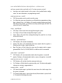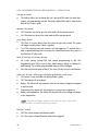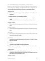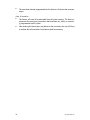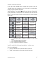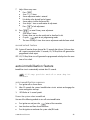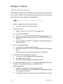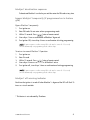
1
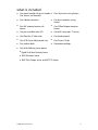
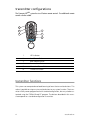
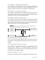
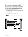
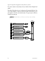
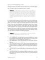
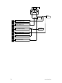
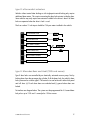
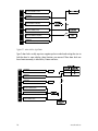
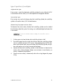
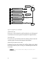
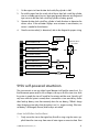
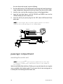
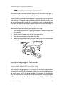
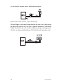
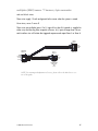
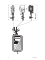
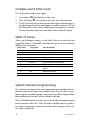
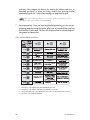
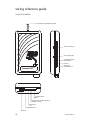
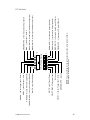
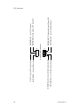
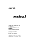
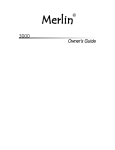
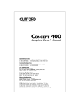
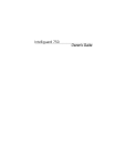
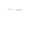
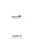
Concept 650MkII
installation guide
© 2007 Directed Electronics Vista, CA N919730P 01-07
IMPORTANT! The Clifford Concept 650MkII system is designed to be
installed in any petrol or common rail diesel vehicle with a 12-volt battery.
Bitwriter®, Code Hopping®, Directed®, Doubleguard®, ESP®, FailSafe®, Ghost Switch®, Learn Routine™, Nite-Lite®,
Nuisance Prevention®, NPC®, Revenger®, Silent Mode™, Soft Chirp®, Stinger®, Valet®, Vehicle Recovery System™,
VRS™, and Warn Away® are all Trademarks or Registered Trademarks of Directed Electronics, Inc., Vista,
California.
contents
what is included . . . . . . . . . . . . . .3
transmitter configurations . . . . . .4
transmitter functions . . . . . . . . . .4
standard configuration . . . . . . .5
primary harness wire connection
guide . . . . . . . . . . . . . . . . . . . . . . .6
primary harness wiring diagram 6
primary harness wiring guide . .7
secondary harness wire connection
guide . . . . . . . . . . . . . . . . . . . . . .10
secondary harness wiring diagram
10
secondary harness wiring guide10
pigtail harness wire connection
guide (h3 and h4) . . . . . . . . . . . .10
h3 connector (male) . . . . . . . .10
h4 connector (female) . . . . . . .11
peripheral plug-in harnesses . . .23
super bright blue led, 2-pin white
plug . . . . . . . . . . . . . . . . . . . .23
plain-view valet switch, 2-pin blue
plug . . . . . . . . . . . . . . . . . . . .24
multiplex (MUX) sensor ‘T’ harness, 4-pin connector . . . . . . .25
tilt sensor . . . . . . . . . . . . . . . .27
glass tamper sensor . . . . . . . .27
remote adjustable proximity sensor . . . . . . . . . . . . . . . . . . . . .27
ultrasonic sensor . . . . . . . . . . .28
omnisensor . . . . . . . . . . . . . .28
arming/disarming diagnostics . .28
arming . . . . . . . . . . . . . . . . . .28
disarming . . . . . . . . . . . . . . . .29
system status chirps . . . . . . . . . .29
remote siren silencing . . . . . . . .29
door lock harness wire connection
multiple event total recall . . . . .30
guide . . . . . . . . . . . . . . . . . . . . . .12
door lock harness wiring guide 12
identifying the door lock system .
12
type A: positive-triggered, relaydriven system . . . . . . . . . . . . .13
type B: negative-triggered, relaydriven system . . . . . . . . . . . . .14
type C: reversing polarity system .
15
type D: after-market actuators 17
type E: Mercedes-Benz and Audi
(1985 and newer) . . . . . . . . . .17
type F: one-wire system . . . . .18
type G: positive (+) multiplex .19
type H: negative (-) multiplex .20
table of zones . . . . . . . . . . . . . . .30
515U self-powered smartsiren . .21
siren installation instructions . .21
passenger compartment . . . . . . .22
mounting the control unit . . . .22
mounting the receiver/antenna 23
system features programming . .30
cliffnet wizard pro installation
software programming . . . . . .31
manual programming instructions
31
user selectable features . . . . . .32
user selectable features descriptions - column one . . . . . . . . .33
user selectable features descriptions - column two . . . . . . . . .34
user selectable features descriptions - column three . . . . . . . .35
installer selectable features . . .37
installer selectable features
descriptions - column one . . . .37
installer selectable features
descriptions - column two . . . .39
installer selectable features
descriptions - column three . . .40
programming notes . . . . . . . .41
smart power up II . . . . . . . . . . . .44
remote control sensor disable . .44
mux (multiplex) sensors . . . . . . .45
adjusting the 506T glass tamper
sensor . . . . . . . . . . . . . . . . . . .45
adjusting and testing the 509U
ultrasonic sensor . . . . . . . . . . .45
adjusting the 507C tilt/motion
sensor . . . . . . . . . . . . . . . . . . .45
adjusting the proximity sensor .46
adjusting the omnisensor . . . . . .48
second unlock feature . . . . . . .49
auto-immobilisation feature . . .49
auto-immobilisation sequence .49
blackjax* deactivation sequence .
51
bypass blackjax* temporarily (if
programmed on in feature grid) .
51
blackjax* off warning indicator51
certificate of installation . . . . . .52
troubleshooting . . . . . . . . . . . . .52
wiring reference guide . . . . . . . .54
control module . . . . . . . . . . . .54
H1 harness . . . . . . . . . . . . . . .55
H2 harness . . . . . . . . . . . . . . .56
notes . . . . . . . . . . . . . . . . . . . . . .57
blackjax* feature . . . . . . . . . . . .50
blackjax activation sequence . .50
2
www.directed.com
what is included
z
One control module with 8-wire immob- z
iliser harness and clamshell
One 18-pin main wiring harness
z
Two 5-button transmitters
z
One 8-pin secondary wiring
harness
z
One XHF antenna/receiver with
harness
z
One Cliffnet Dataport extension
harness
z
One pre-wired Blue status LED
z
One MUX sensor port ‘T’ harness
z
One PlainView 2 Valet switch
z
One hardware pack
z
One 515U Smart Self-powered siren
z
One Owner’s Guide
z
Two window decals
z
Presentation envelope
z
One of the following sensor options
z
Digital Dual Zone Proximity Sensor
z
509U Ultrasonic Sensor
z
506T Glass Tamper Sensor and 507C Tilt Sensor
© 2007 directed electronics
3
transmitter configurations
The Concept 650MkII system has two 5-button remote controls. Two additional remote
controls can be added.
1
2
4
3
5
6
1.
LED Indicator
2.
Arm/Disarm Button
3.
Boot Release Button
4.
Remote Start Button
5.
Silent Arm/Disarm Button
6.
Clifford G5 Button
transmitter functions
This system uses computer-based code learning to learn the transmitter buttons. This
makes it possible to assign any transmitter button to any system function. The transmitter initially comes programmed with standard configuration, but may also be customised using the CliffNet Wizard PC program. The buttons described in this manual correspond to a standard configuration transmitter.
4
www.directed.com
standard configuration
Button
The arming and disarming functions are controlled by this button.
Button
The boot release or accessory output A is controlled by this button.
Button
This button is used to control remote start on the optional Intellistart 4 module.
Button
Silent arm and disarm is controlled by this button.
Button, then
Button
Accessory B output is controlled by these buttons.
Button, then
Button
These buttons activate the optional SmartWindows module.
Button, then
Button
Accessory C output is controlled by these buttons.
Button twice, then
Button
These buttons activate/deactivate remote valet mode.
Button twice, then
Button
These buttons disable the sensors.
Button twice, then
Button
These buttons enter safe start mode for manual transmission vehicles and activate
Autostart mode.
Button three times, then
Button
These buttons adjust the dual zone Proximity sensor.
Button three times, then
Button
These buttons adjust the omnisensor.
© 2007 directed electronics
5
primary harness wire connection guide
primary harness wiring diagram
6
H1/1
___ WHITE
H1/2
___ VIOLET/BLACK
H1/3
___ N/A
H1/4
___ VIOLET
H1/5
___ GREEN/WHITE
H1/6
___ PINK/BLACK
(-) Accessory C Output (200mA)
H1/7
___ BLUE/WHITE
(-) Second Unlock Output (200mA)
H1/8
___ WHITE/BLUE
(-) Accessory B Output (200mA)
H1/9
___ RED/WHITE
(-) Accessory A Output (200mA)
H1/10
___ WHITE
H1/11
___ YELLOW/WHITE
(-) Horn Honk Output (200mA)
H1/12
___ ORANGE
Ground When Armed (500mA)
H1/13
___ GREY
H1/14
___ GREEN
H1/15
___ GREEN/WHITE Normally Closed Input Zone 6 - Connected to H1/5
H1/16
___ BLUE
H1/17
___ BLACK/WHITE
Interior Light Illumination Output (30)
H1/18
___ BLACK/WHITE
(+) or (-) Interior Light Illumination Input (87)
Indicator Light Flash 1 Output
Tachometer Input
Not Used
(+) Door Trigger Input - Zone 4
Ground (Connected to H1/15)
Indicator Light Flash 2 Output
(-) Bonnet Input - Zone 6
(-) Door Trigger Input - Zone 4
(-) Boot Input - Zone 5
www.directed.com
primary harness wiring guide
This guide describes in detail the connection of each wire. Also included are possible
applications of each wire. This system was designed with the ultimate in flexibility and
security in mind. Many of the wires have more than one possible function. Please read
the instructions carefully to ensure a thorough understanding of this unit and how it
operates.
h1/1 and h1/10 white indicator light flash outputs
These wires are the output of an on-board dual make relay and should be connected
to wires in the vehicle that control the indicators. The dual outputs are designed for
European vehicles with isolated indicator light systems. If the vehicle’s indicator lights
are controlled by a single wire, connect both WHITE wires to this single wire.
IMPORTANT! The polarity of this wire is determined by the connection of the H4/3
light flash input wire. Always confirm the light flash polarity before connecting H4/3
or damage to the vehicle’s lighting system could occur.
h1/2 violet/black tachometer input
This wire monitors engine speed for Blackjax* and door locking. Connect it to one of
the following sources; the negative side of the coil, the uncommon wire on any fuel
injector, or for diesel vehicles the Directed 454T alternator adaptor. If installing with
Intellistart*, only connect the Intellistart* wire; DO NOT use this wire.
h1/4 violet (+) door trigger input - zone 4
Connect this violet wire to a wire that shows (+)12V when any door is opened. This
wire will report Zone 4.
h1/5 green/white ground (connected to h1/15)
This wire is pre-connected to the normally closed trigger wire H1/15.
h1/6 pink/black (-) accessory C output (200mA)
This wire produces a 200mA output when activated by the remote control and can be
used to operate a variety of accessories. All accessory outputs can be programmed to
different types of outputs. Please see Programming Note #5.
* This feature/accessory is not evaluated by Thatcham.
© 2007 directed electronics
7
h1/7 blue/white (-) second unlock output (200mA)
This wire produces a (-) 200mA output for vehicles with progressive/selective door
unlock, where the driver’s door unlocks first and the remaining doors unlock with a
second turn of the key in the keyswitch or a second press of the unlock button.
h1/8 white/blue (-) accessory B output (200mA)
This wire produces a 200mA output when activated by the remote control and can be
used to operate a variety of accessories. All accessory outputs can be programmed to
different types of outputs. Please see Programming Note #5.
h1/9 red/white (-) accessory A output (200mA)
This wire produces a 200mA output when activated by the remote control and can be
used to operate a variety of accessories. This is often used to operate a boot/hatch
release or other relay-driven function. All accessory outputs can be programmed to
different types of outputs. Please see Programming Note #5.
IMPORTANT! Never use this wire to drive anything but a relay or a low-current input!
The transistorised output can only supply 200 mA of current. Connecting directly to a
solenoid, motor, or other high-current device will cause it to fail.
H1/6 PINK/BLACK,
H1/8 WHITE/BLUE
OR
H1/9 RED/WHITE
(+) 12V IF (+) SWITCHED
(-) GROUND IF (-) SWITCHED
87 87A
85
86
30
(+) 12V CONSTANT FUSED
SWITCHED (+) OR (-)
OUTPUT WIRE
h1/11 yellow/white (-) horn honk output (200mA)
This wire is a low current output (200mA) for the horn to sound when the system has
been triggered. It can be programmed to either pulse or latch on when the alarm is
triggered.
h1/12 orange (500mA) (Ground when Armed)
This wire provides a (-) ground output as long as the system is armed and will turn off
when the system is disarmed. This wire does not provide a ground when
Autoimmobilised only. This output can be used to control additional accessories such
as window closers, voice modules, or pagers.
h1/13 grey (-) bonnet input - zone 6
Connect this wire to the bonnet pin switch. If the bonnet is opened when the alarm is
8
www.directed.com
armed, this wire will trigger the system.
h1/14 green (-) door trigger input - zone 4
Most vehicles use negative door trigger circuits. Connect the GREEN wire to a wire
showing ground when any door is opened. When connecting to newer model vehicles
there is sometimes the need to use individual door trigger wires. This wire will report
Zone 4.
NOTE: If using a door trigger wire that has a delay, the installer-selectable programming grid or the Cliffnet Wizard can be used to turn the door ajar warning off.
INTERIOR LIGHT
GREEN
(-) DOOR SWITCH
(+) 12V
h1/15 green/white normally closed input - zone 6 (pre-connected to h1/5)
This wire is pre-connected to ground on H1/5. Some vehicles are factory fitted with
normally closed bonnet pin switches which can be connected to this wire. Or alternatively, it can be connected to ground after being looped through external ancillary
equipment such as mountain bikes, spot lamps, spare wheels, in-dash CD players, etc.
The input can also be used for connection to a heated rear window switched wire.
This last option is especially useful as if the rear windscreen was removed whilst the
alarm was armed the alarm would trigger.
h1/16 blue (-) boot input - zone 5
This input will respond to a negative input with an instant trigger. Connect to (-) boot
pins and it will report on Zone 5.
h1/17 black/white interior light illumination output (30)
Connect this wire to the interior light circuit trigger wire or the alarm’s door trigger
input wire H1/4 or H1/14. When the alarm is disarmed this wire will provide an output to turn on the interior light for 30 seconds.
h1/18 black/white interior light illumination input (87)
This wire determines the output of the BLACK/WHITE H1/17 wire on the main 18-pin harness. If the vehicle has a negative switched interior light circuit, ground this wire; if the vehi© 2007 directed electronics
9
cle has a positive switched interior light circuit, attach this wire to a 12 volt constant source.
secondary harness wire connection guide
secondary harness wiring diagram
H2/1
___ BROWN/BLACK
H2/2
___ WHITE/BLACK
H2/3
___ VIOLET/BLACK
Lock 87 (Normally Open)
H2/4
___ BROWN/WHITE
Brake Light Output (30)
H2/5
___ BLUE/BLACK
H2/6
___ VIOLET
H2/7
___ GREEN/BLACK
H2/8
___ BROWN/RED
Unlock 87A (Normally Closed)
Lock 87A (Normally Closed)
Unlock 30 (Common)
Unlock 87 (Normally Open)
Lock 30 (Common)
Brake Light (+) 12V Input (87)
secondary harness wiring guide
NOTE: For the wires not discussed below, please refer to the Door Lock Harness
Wire Connection Guide section.
h2/4 brown/white brake light output
When activated by the Blackjax* feature this wire powers the brake light circuit from
the 12-volt source on H2/8.
h2/8 brown/red brake light (+) 12V input
This is the polarity source for the brake light output and must be 12 volt constant.
pigtail harness wire connection guide (h3
and h4)
h3 connector (male)
Locate the ignition and starter wires using a multimeter. Cut the appropriate wire and
attach the key side and car side wires to the corresponding wires on the four-pin
immobiliser harness.
10
www.directed.com
* This feature is not evaluated by Thatcham.
H3/1 Starter Side
H3/4 Ignition Car Side
H3/2 Starter Key Side
H3/3 Ignition Key Side
Starter
Ignition
x
CUT
x
CUT
NOTE: The current handling capacity of each immobilisation circuit is 20 amps continuous and 30 amps peak.
h4 connector (female)
BLACK - H4/1
Ground
BLACK - H4/4
(+) 12V Input
BLACK - H4/2
Ground
BLACK - H4/3 Indicator
Light Flash Input
Connect the BLACK wires H4/1 and H4/2 to separate ground locations using a factory bolt that does NOT have any vehicle component grounds attached to it or drill a
new hole if required. A screw should only be used in conjunction with a two-sided
lock washer. Under dash brackets and door sheet metal are not acceptable ground
points.
© 2007 directed electronics
11
The Black H4/3 wire is the input for the on-board dual make indicator light flash
relay. If the indicators are switched positive connect this wire to a 12 volt constant
source at the vehicle fusebox, if they are switched negative connect to ground. (Make
sure the supplied fuseholder and 20-amp fuse is used.)
Connect the H4/4 power supply wire to an unfused source at the vehicle’s fusebox.
Use the supplied fuse holder and a 5 amp fuse).
IMPORTANT! Always confirm light fash polarity before connecting Hf1/H12 or damage to the vehicle lighting system could occur.
NOTE: Remove all tags from H3 and H4 wires after installation.
door lock harness wire connection guide
door lock harness wiring guide
h2 connector central door locking
The system has door lock relays on-board, and can directly interface with most central locking systems drawing 20 amps or less.
identifying the door lock system
There are eight different types of common door lock circuits found in vehicles (some
vehicles use more unusual systems). The eight most common systems are:
z
Type A: Three-wire (+) pulse controlling factory lock relays.
z
Type B: Three-wire (-) pulse controlling factory lock relays.
z
Type C: Direct-wired reversing-polarity switches. The switches are wired directly
to the motors. This type of door lock system has no factory relays.
z
Type D: Aftermarket door servo driven systems. These include slave systems without an actuator in the driver’s door but with factory actuators in all the other
doors. These can be controlled with the installation of an aftermarket motor in the
driver’s door.
z
Type E: Electronically-activated vacuum systems. This may require special programming of the system.
z
Type F: One-wire system.
z
Type G: Positive (+) multiplex resistor-based circuit.
z
Type H: Negative (-) multiplex resistor-based circuit.
12
www.directed.com
type A: positive-triggered, relay-driven system
The system can control Type A door locks directly, with no additional parts. The switch
will have three wires on it; one will test (+)12 volt constantly. The others will alternately pulse (+)12 volt when the switch is pressed to the lock or unlock position.
If you cannot get to the switch, and you find a set of wires that pulse (+)12 volt alternately on lock and unlock, make sure that it is not a Type C direct-wire system.
Cut the wire that pulses (+)12 volt on lock, and then operate the switch to unlock.
■
■
If all doors unlock, the vehicle uses type A system.
■
If you lose all door lock operation of one or more, but not all motors, and other
doors still work, you have cut a wire leading directly to one or more motors. You
must instead find the actual wires leading to the switch.
If you lose all door lock operation in both directions, you are operating the master switch in a Type C system.
IMPORTANT! Remember that these wires' functions reverse between Type A and Type
B.
H2/1
BROWN/BLACK
UNLOCK #87A NORMALLY CLOSED
NOT USED
FACTORY LOCK
SWITCH
LOCK
H2/2
WHITE/BLACK
LOCK #87A NORMALLY CLOSED
H2/3
VIOLET/BLACK
LOCK #87 NORMALLY OPEN (INPUT)
NOT USED
15A
H2/5
BLUE/BLACK
UNLOCK #30 COMMON (OUTPUT)
H2/6
VIOLET
UNLOCK #87 NORMALLY OPEN (INPUT)
H2/7
GREEN/BLACK
LOCK #30 COMMON (OUTPUT)
UNLOCK
VEHICLE FUSED
+12 VOLT CONSTANT
VEHICLE (+)
UNLOCK TRIGGER
CIRCUIT
VEHICLE (+)
LOCK TRIGGER
CIRCUIT
TO FACTORY
RELAYS
© 2007 directed electronics
13
type B: negative-triggered, relay-driven system
This system is common in many Toyotas, Nissans, Hondas and most European Ford
vehicles.
The switch will have three wires on it, and one wire will test ground all the time. One
wire will pulse negative (-) when the switch locks the doors, and the other wire will
pulse negative (-) when the switch unlocks the doors. This type of system is difficult to
mistake for any other type.
IMPORTANT! Remember that these wires' functions reverse between Type A and Type
B.
FACTORY LOCK
SWITCH
LOCK
H2/1
BROWN/BLACK
UNLOCK #87A NORMALLY CLOSED
NOT USED
H2/2
WHITE/BLACK
LOCK #87A NORMALLY CLOSED
NOT USED
H2/3
VIOLET/BLACK
LOCK #87 NORMALLY OPEN (INPUT)
H2/5
BLUE/BLACK
UNLOCK #30 COMMON (OUTPUT)
15A
H2/6
VIOLET
UNLOCK #87 NORMALLY OPEN (INPUT)
H2/7
GREEN/BLACK
LOCK #30 COMMON (OUTPUT)
UNLOCK
TO CHASSIS
GROUND
VEHICLE (-)
UNLOCK TRIGGER
CIRCUIT
VEHICLE (-)
LOCK TRIGGER
CIRCUIT
TO FACTORY
RELAYS
14
www.directed.com
type C: reversing polarity system
Use these instructions if the power door lock switch has four or five heavy-gauge
wires. This type of switch has two outputs that rest at (-) ground.
IMPORTANT! To interface with these systems, you must cut two switch leads. The
relays must duplicate the factory door lock switches’ operation. The master switch will
have one or two ground inputs, one (+)12V input, and two switch outputs going directly to the slave switch and through to the motors. These outputs rest at (-) ground. The
lock or unlock wire is switched to (+)12V, while the other wire is still grounded, thus
completing the circuit and powering the motor. This will disconnect the switch from the
motor before supplying the motor with (+)12V, avoiding sending (+)12V directly to () ground.
It is critical to identify the proper wires and locate the master switch to interface properly. Locate wires that show voltage when the switch is moved to the lock or unlock
position. Cut one of the suspect wires and check operation of the locks from both
switches. If one switch loses all operation in both directions then you have cut one of
the correct wires and the switch that is entirely dead is the master switch. If both
switches still operate in any way and one or more door motors have stopped responding entirely, you have cut a motor lead. Reconnect it and continue to test for another
wire. Once both wires have been located and the master switch identified, cut both
wires and interface as described in the following paragraphs.
WARNING! If these wires are not connected properly, you will send (+)12V directly
to (-) ground, possibly damaging the alarm or the factory switch.
z
H2/1 WHITE/BLACK: Once both door lock wires are located and cut, connect
the white/black wire to the master switch side of the lock wire. The master switch
side will show (+)12V when activated and (-) ground at rest.
z
H2/2 GREEN/BLACK: Connect the green/black wire to the motor side of the
lock wire.
z
H2/3 VIOLET/BLACK and H2/4 VIOLET: These wires must be connected to constant (+)12 volts (via a 15-amp fuse). The best connection point for these wires
is directly to the positive (+) battery post or an unfused source at the vehicle fusebox.
z
H2/5 BLUE/BLACK: Connect the blue/black wire to the motor side of the unlock
wire.
z
H2/6 BROWN/BLACK: Connect the brown/black wire to the master switch side
of the unlock wire. The master switch side will show (+)12V when activated and
(-) ground at rest.
© 2007 directed electronics
15
(+) 12V
X
X
16
H2/1
BROWN/BLACK
UNLOCK #87A NORMALLY CLOSED
H2/2
WHITE/BLACK
LOCK #87A NORMALLY CLOSED
H2/3
VIOLET/BLACK
LOCK #87 NORMALLY OPEN (INPUT)
H2/5
BLUE/BLACK
UNLOCK #30 COMMON (OUTPUT)
H2/6
VIOLET
UNLOCK #87 NORMALLY OPEN (INPUT)
H2/7
GREEN/BLACK
LOCK #30 COMMON (OUTPUT)
15A
CUT X
CUT X
MOTOR (+)
UNLOCK WIRE
MOTOR (+)
LOCK WIRE
+ 12V FUSED
7.5A /MOTOR
www.directed.com
type D: after-market actuators
Vehicles without central door locking or with single-point central locking only require
additional door motors. This requires mounting the door lock actuator inside the door.
Some vehicles may only require one actuator installed in the driver's door if all door
locks are operated when the driver's lock is used.
The fuse used on 12 volt inputs should be 7.5A per motor installed in the vehicle.
H2/1
BROWN/BLACK
UNLOCK #87A NORMALLY CLOSED
H2/2
WHITE/BLACK
LOCK #87A NORMALLY CLOSED
H2/3
VIOLET/BLACK
LOCK #87 NORMALLY OPEN (INPUT)
H2/5
BLUE/BLACK
UNLOCK #30 COMMON (OUTPUT)
H2/6
VIOLET
UNLOCK #87 NORMALLY OPEN (INPUT)
H2/7
GREEN/BLACK
LOCK #30 COMMON (OUTPUT)
type E: Mercedes-Benz and Audi (1985 and newer)
Type E door locks are controlled by an electrically activated vacuum pump. Test by
locking doors from the passenger key cylinder. If all the doors lock, the vehicle's door
lock system can be wired as type E. The control wire can be found in either kick panel
and will show (+)12 volt when doors are unlocked and (-) ground when doors are
locked.
To interface see diagram below. The system must be programmed for 3.5 second door
lock pulses up to 1993 and 1 second pulse 1994 or newer.
© 2007 directed electronics
17
H2/1
BROWN/BLACK
UNLOCK #87A NORMALLY CLOSED
H2/2
WHITE/BLACK
LOCK #87A NORMALLY CLOSED
H2/3
VIOLET/BLACK
LOCK #87 NORMALLY OPEN (INPUT)
H2/5
BLUE/BLACK
UNLOCK #30 COMMON (OUTPUT)
H2/6
VIOLET
UNLOCK #87 NORMALLY OPEN (INPUT)
H2/7
GREEN/BLACK
LOCK #30 COMMON (OUTPUT)
type F: one-wire system
Type F door locks usually require a negative pulse to unlock and cutting the wire to
lock the door. In some vehicles, these functions are reversed. These door locks are
found most commonly in Mitsubishis, Proton and Lotus.
H2/1
BROWN/BLACK
UNLOCK #87A NORMALLY CLOSED
H2/2
WHITE/BLACK
LOCK #87A NORMALLY CLOSED
H2/3
VIOLET/BLACK
LOCK #87 NORMALLY OPEN (INPUT)
H2/5
BLUE/BLACK
UNLOCK #30 COMMON (OUTPUT)
H2/6
VIOLET
UNLOCK #87 NORMALLY OPEN (INPUT)
H2/7
GREEN/BLACK
LOCK #30 COMMON (OUTPUT)
18
NOT USED
NOT USED
www.directed.com
type G: positive (+) multiplex
single-resistor type
If one resistor is used in the door lock switch/key cylinder, the wire will pulse (+)12V
in one direction and less than (+)12V when operated in the opposite direction.
two-resistor type
If two resistors are used in the factory door lock switch/key cylinder, the switch/key
cylinder will read less than (+)12V in both directions.
determining the proper resistor values
To determine the resistor values, the door lock switch/key cylinder must be isolated
from the factory door lock system. For testing, use a calibrated digital multimeter that
is set to ohms.
IMPORTANT! To ensure an accurate resistance reading, do not touch the resistor or
leads during testing.
1.
Cut the output wire from the door lock switch/key cylinder in half.
2.
Test with the meter from the switch side of the cut door lock switch/key cylinder
wire to a reliable constant (+)12V source. Some good constant (+)12V references are the power input source to the door lock switch/key cylinder, the ignition switch power wire, or the (+) terminal of the battery.
3.
Operate the door lock switch/key cylinder in both directions to determine the
resistor values. If the multimeter displays zero resistance in one direction, no
resistor is needed for that direction.
4.
Once the resistor value(s) is determined, refer to the wiring diagram for proper
wiring.
© 2007 directed electronics
19
(+)12V
CONSTANT FUSED
BROWN/BLACK
UNLOCK #87A NORMALLY CLOSED
NOT USED
H2/2
WHITE/BLACK
LOCK #87A NORMALLY CLOSED
NOT USED
H2/3
VIOLET/BLACK
LOCK #87 NORMALLY OPEN (INPUT)
H2/5
BLUE/BLACK
UNLOCK #30 COMMON (OUTPUT)
H2/1
DOOR LOCK SWITCH/
KEY CYLINDER
LOCK
UNLOCK
15A
H2/6
VIOLET
UNLOCK #87 NORMALLY OPEN (INPUT)
H2/7
GREEN/BLACK
LOCK #30 COMMON (OUTPUT)
VEHICLE FUSED
+12 VOLT CONSTANT
LOCK RESISTOR
(IF REQUIRED)
UNLOCK RESISTOR
(IF REQUIRED)
BCM
type H: negative (-) multiplex
single-resistor type
If one resistor is used in the door lock switch/key cylinder, the wire will pulse ground
in one direction and resistance to ground when operated in the opposite direction.
two-resistor type
If two resistors are used in the factory door lock switch/key cylinder, the door lock
switch/key cylinder will read resistance to ground in both directions.
determining the proper resistor values
To determine the resistor values, the door lock switch/key cylinder must be isolated
from the factory door lock system. For testing, use a calibrated digital multimeter that
is set to ohms.
IMPORTANT! To ensure an accurate resistance reading, do not touch the resistor or
leads during testing.
20
www.directed.com
1.
Cut the output wire from the door lock switch/key cylinder in half.
2.
Test with the meter from the switch side of the cut door lock switch/key cylinder
wire to a reliable ground source. Some good ground references are the ground
input source to the door lock switch/key cylinder or battery ground.
3.
Operate the door lock switch/key cylinder in both directions to determine the
resistor values. If the multimeter displays zero resistance in one direction, no
resistor is needed for that direction.
4.
Once the resistor value(s) is determined, refer to the diagram for proper wiring.
CHASSIS
GROUND
H2/1
BROWN/BLACK
UNLOCK #87A NORMALLY CLOSED
NOT USED
H2/2
WHITE/BLACK
LOCK #87A NORMALLY CLOSED
NOT USED
DOOR LOCK SWITCH/
KEY CYLINDER
LOCK
H2/3
VIOLET/BLACK
LOCK #87 NORMALLY OPEN (INPUT)
H2/5
BLUE/BLACK
UNLOCK #30 COMMON (OUTPUT)
H2/6
VIOLET
UNLOCK #87 NORMALLY OPEN (INPUT)
H2/7
GREEN/BLACK
LOCK #30 COMMON (OUTPUT)
UNLOCK
LOCK RESISTOR
(IF REQUIRED)
15A
TO CHASSIS
GROUND
UNLOCK RESISTOR
(IF REQUIRED)
BCM
515U self-powered smartsiren
The siren transmits a two-way digital signal between itself and the control unit. If a
thief disconnects power and/or cuts or tampers with any or all of the siren wires while
the system is armed, the siren will sound for five minutes and then reset. Since this will
only occur while the system is armed, there is no need for a siren override key. Unlike
other back-up battery sirens that constantly drain the car battery, Clifford's design
draws charging current only when the ignition is on (i.e., engine running). If the internal battery is discharged, the arm/disarm chirps are muted.
siren installation instructions
1.
Firmly secure the siren to the engine bay firewall or wing using the screws supplied. Mount the siren away from areas of water ingress or excessive heat. Point
© 2003 directed electronics, inc.
21
the siren downward to avoid moisture collecting.
2.
Run the cable from the 515U Self-Powered Siren through the firewall into the passenger compartment, being careful not to tear the pins from the end of the cable.
3.
Insert the siren wires into the siren plug as shown in the diagram below.
4.
Insert the 3-pin data harness with the YELLOW and GREEN wires into the
CliffNet Wizard port on the control unit.
5.
Insert the red two pin power plug into the SSPS (Smart Self Powered Siren)
power port.
NOTE: The vehicle must be driven for a total of eight hours after the siren has been
installed in order to sufficiently charge the siren’s back-up battery.
2-AMP
FUSE
BACK VIEW OF
SIREN PLUG
BLACK
RED
YELLOW
GREEN
YELLOW
GREEN
BLACK (-) GROUND
5-AMP
FUSE
CONTROL UNIT
ACCESSORIES
OR WIZARD
RED (+) BATTERY
DATA PORT
BATTERY
passenger compartment
mounting the control unit
NOTE: The Concept 650MkII control unit must be installed inside the vehicle. Under
no cricumstances should the unit be installed under the bonnet or other similarly hostile environment.
Select an area behind the dash that will allow you to securely fasten the unit using the
screws provided in the hardware pack. Do not mount the unit near moving parts or
in direct path of air blowing from the heater vents.
22
www.directed.com
mounting the receiver/antenna
NOTE: Do not bundle excess cable as this will reduce the range.
The receiver/antenna position should be discussed with the vehicle owner prior to
installation since the antenna may be visible to the driver.
The best position to locate the receiver/antenna is centered high on either the front or
rear windshield. For optimal range, the antenna should be mounted vertically. It can
be mounted horizontally in relation to the windshield or under the dashboard away
from metal, but range will be reduced. Metallic window tint can also affect range, so
this should be a consideration when determining the mounting location.
After determining the best mounting location, follow these steps:
1.
Clean the mounting area with a quality glass cleaner or alcohol to remove any
dirt or residue.
2.
Plug the receiver/antenna cable into the receiver/antenna.
3.
Mount the receiver/antenna with double-sided tape.
4.
Route the receiver/antenna cable down the window pillar to the control module
and plug the cable into the control module.
peripheral plug-in harnesses
super bright blue led, 2-pin white plug
The super bright LED operates at (+) 2V DC. Make sure the LED wires are not shorted to ground as the LED will be damaged. Multiple LEDs can be used, but they must
be wired in series. The LED can be top-mounted or flush-mounted. If top-loading the
LED with a bezel, the LED fits into a 5/16-inch mounting hole. If flush-mounting the
LED from the back of a panel, drill a mounting hole using a 17/64-inch drill bit. Make
© 2007 directed electronics
23
sure you check for clearance prior to drilling the mounting hole.
plain-view valet switch, 2-pin blue plug
The Valet/Program switch should be accessible from the driver’s seat. It plugs into the
blue port on the side of the unit. The switch is coded for protection so it need not be
hidden. Consider how the switch will be used before choosing a mounting location.
Check for rear clearance before drilling a 9/32-inch hole and mounting the switch.
24
www.directed.com
multiplex (MUX) sensor ‘T’ harness, 4-pin connector
red and black wires
These wires supply 12 volts and ground to the sensor when the system is armed.
blue wires, zone 3 zone 8
These wires are multiplex inputs. If a (-) input of less than 0.8 seconds is supplied to
either wire, the Warning Zone response will occur. A (-) input of longer than 0.8 seconds to either wire will initiate the triggered sequence and report Zone 3 or Zone 8.
MUX 1
ZONE 3
RED
BLACK
BLUE
CONTROL
MODULE
BLACK
FOR 507C
MUX 2
ZONE 8
RED
BLACK
BLUE
RED
BLACK
BLUE
BLUE
WHITE
WHITE
CONNECTOR
FOR 509U
OR
506T
NOTE: For mounting and adjustment of sensors, please refer to the Mux Sensors section of this guide.
© 2007 directed electronics
25
507C (507M)
Concept 650MkII
26
www.directed.com
tilt sensor
The 507C tilt sensor detects when the vehicle is being raised in an attempt to either
remove the wheels/tires or tow the vehicle. It is capable of independently learning the
vehicle’s initial angles of vertical and horizontal inclination each time the vehicle is
parked, ensuring the most accurate tilt (vertical) and motion sensing (horizontal) possible.
The sensor control module must be mounted at an angle no greater than 45 degrees,
with respect to the horizontal plane of the vehicle, and it must be mounted with the
case top facing upward. We recommend mounting the control module to the floor of
the vehicle. To mount the control module, fasten the unit with either Velcro or screws.
Plug the sensor into the Black T-harness connector. It will report zone 3 if triggered.
NOTE:The Tilt sensor should not be mounted in any place where rapid temperature
changes could affect it such as centre console above vehicle exhaust pipe.
glass tamper sensor
The 506T Glass Tamper Sensor is a low-current device that provides an added level of
protection to an existing security system by detecting sounds that have the acoustic signature of breaking glass or metal-to-glass impacts. It consumes less than 1 mA of current. Plug the sensor into the White T-harness connector. It will report zone 8 if triggered.
remote adjustable proximity sensor
The proximity sensor input circuitry has been improved for G5 so the sensor only has
power when the alarm is armed. While driving this protects highly sensitive vehicle
electronics (i.e. radar detectors) that can be affected by outside interference. However,
this does change the way the sensor is adjusted but will not affect normal operation
of the sensor.
Inside the vehicle's headliner is the optimal mounting location for this sensor and
should always be the first choice. The sensor should face down, centered side to side,
with the wire harness exiting toward the front or rear of the vehicle.
If headliner mounting is not possible, the sensor can be placed in a lower area of the
vehicle, but field size and sensitivity may be affected. The center console may be
appropriate.
Plug the sensor into the Proximity sensor port on the side of the control unit using the
shielded 3-wire harness. It will report zone 1 if triggered.
© 2007 directed electronics
27
NOTE: Never place the sensor behind any metal brackets or under console pockets
that will have coins or other metal objects in it.
ultrasonic sensor
The optional 509U Ultrasonic sensor is used to provide coverage of a vehicle’s interior cabin area. The sensors detect movement inside the vehicle by sensing air disturbance. They should trigger the alarm if a thief has gained access to the interior of your
vehicle.
mounting the control module and transducers
1.
2.
3.
4.
Choose a location under the dashboard for the control module that is close
enough that the wire harness can reach the alarm control module and the
transducers will reach the top of the A-pillar on both driver and passenger
sides.
One transducer is longer than the other, so mount the transducer with the
longest harness furthest from the control module. Use the screws provided
or insert the mounting tabs between the dashboard and windscreen pillar.
Angle the sensors towards the top centre of the rear window. If mounted at
the top of the A-pillars make sure the transducers position does not affect
use of the sunvisor.
Route the sensor cables to the 509U control module and plug-in.
Plug the sensor into the White T-harness connector. It will report zone 8 if triggered.
omnisensor
The optional Omnisensor is designed to give the ultimate in impact detection without
the possibility of false alarms that are common with less sophisticated sensor.
The omnisensor can be located in either the passenger or engine compartment. It must
be firmly mounted with the indicator arrow pointing UP to a vertical metal surface. For
best results it must be secured with screws using ALL FOUR mounting points.
Plug the sensor into the Green Omnisensor port on the side of the control unit. It will
report zone 2 if triggered.
arming/disarming diagnostics
The systems microprocessor monitors and reports all active and violated zones when
arming and disarming the system.
arming
28
www.directed.com
Zones that are triggered at the time the system is armed are reported by an additional set
of status chirps called Malfunction AutoBypass. The specific zone bypassed is then reported by the LED. For more zone information, refer to Table of Zones section of this guide.
disarming
If a zone is triggered, three disarm chirps will sound. The specific zone that was triggered is then reported by the LED when the ignition is turned on. For more zone information, refer to the Table of Zones section of this guide.
system status chirps
Action
No. of Chirps
Description
Arm
2
System armed
Arm
4
System armed with boot or bonnet
active and bypassed (zones 5 and 6)
Arm
2 (5-second pause) 4
System armed with door active and
bypassed (zone 4)
Arm
2 (10-second pause) 4
System armed with sensor active
and bypassed (zones 1, 2, 3, and 8)
Disarm
3
System disarmed with tamper alert
Disarm
1
System disarmed
Disarm
1 (low pitch)
System disarmed
low battery warning
with
transmitter
remote siren silencing
While the siren is sounding, press the arm/disarm button once to silence the siren but
leave the system in the armed state. To disarm the system, press the arm/disarm button a second time.
NOTE: If the remote control battery is low, the siren will generate a single low pitched
chirp when disarming.
© 2007 directed electronics
29
multiple event total recall
This will report the last eight system triggers.
1.
Press and hold
of the PlainView 2 Valet switch.
2.
While still holding
3.
The LED will start to flash to indicate the most recent trigger and proceed down to
the eighth trigger. If fewer than eight triggers are stored in memory, the LED will
flash continuously until the system is armed/disarmed or the ignition is turned on.
For more information, please refer to the Table of Zones section of this guide.
, arm and disarm the system, then release the button.
table of zones
When using the diagnostic functions, use the Table of Zones to see which input has
triggered the system. It is also helpful in deciding which input to use when connecting
optional sensors and switches.
LED Flashes
Trigger type
Input description
1
Data
Optional Proximity Sensor
NOTE: The Warning Zone response does not report on the LED.
2
Data
Optional Omnisensor
3
Mux 1
Optional Tilt/motion Sensor
4
Instant
Door Switch Input
5
Instant
Boot Pin Input
6
Instant
Bonnet or Normally Closed Input
7
Instant
Ignition Input
8
Mux 2
Optional Glass Tamper Sensor or Ultrasonic
Sensor
9
N/A
BlackJax* Activation
10
N/A
Alarm power reset
system features programming
This system has many features that can be programmed to accommodate the user's
personal preferences and make system installation easier. They are listed in two programming grids on the following pages. Many features have default settings that have
been programmed at the factory and are indicated in bold type.
The User Selectable Features grid allows the user and installer to change operational
features through the PlainView 2 Valet. The Installer Selectable Features grid allows
the installer to change input/output functions of the system to integrate with the vehicle’s specific characteristics.
30
www.directed.com
* This feature is not evaluated by Thatcham.
cliffnet wizard pro installation software programming
Cliffnet Wizard Pro provides access to all available system features and some that are
not available when manually programming with the Valet switch. Cliffnet Wizard Pro
is compatible with Microsoft Windows 2000/ME/XP/NT so most programming operations can be accomplished by pointing and clicking with a mouse. This eliminates the
need for programming grids and lengthy programming sequences. For a complete
guide to system programming using the Cliffnet Wizard Pro refer to the Cliffnet
Wizard help menu.
manual programming instructions
It is a good idea to document changes by taking note of all feature changes made in
programming mode.
To enter the User Selectable Features programming:
1.
Ignition on - Turn the ignition to the run position or start the engine.
2.
Hold/Chirp/Release - Press and hold
until a chirp is heard and the LED
turns on, then release the button. You have now entered the feature selection
position of the User Selectable Features grid.
3.
Column select - Press
the same number of times as the desired column. After
a pause the siren will chirp the same number of times as the selected column for
confirmation.
4.
Feature select - Press
the same number of times as the desired feature. The
siren will chirp with each press. The feature can now be changed using the
remote control.
5.
Feature change - Press the
button on the transmitter. If the system chirps
once, the feature has just turned off; if the system chips twice, the feature has just
turned on. If the feature has more than two settings, continue pressing the
arm/disarm button on the transmitter to toggle through the settings.
To advance to the next feature in the same column, press
the same number
of times as the desired feature within 60 seconds; to change a feature in a
different column begin at step 4 by entering the column number first and then
the row number.
6.
Grid Jump - To change a feature in a different feature grid - Press and hold the
button for 10 seconds and you will jump from one grid to another. (e.g. You
are in the user programming grid and would like to jump to the installer grid.
Press and hold
for 10 seconds, you will hear 3 chirps indicating installer
© 2007 directed electronics
31
grid entry. Now program the features by entering the columns and rows as
described previously.) 3 chirps are always heard when entering installer
programming grid and 1 chirp when entering user programming grid.
NOTE: Refer to the Feature Descriptions sections of this guide for important notes and
descriptions of the system features and programming.
7.
Exit programming - Once you have completed programming you can exit programming mode by turning the ignition off or wait 60 seconds without pressing
the PlainView 2 Valet switch. The siren will chirp three times to indicate programming mode has been exited.
user selectable features
Off / On
Off/On/Quiet
Off/Ignition/RPM
Off/Ignition
Off/On
Off/On
Off/On
Off/On
Off/On
*
This feature is only available with optional IntelliStart connected.
**
This feature is only available with optional SmartWindows connected.
*** 5-button transmitters only. To program 4-button remote controls use New remote learn in column 3.
**** This feature is not evaluated by Thatcham.
32
www.directed.com
user selectable features descriptions - column one
add new remote (only applicable with 5 button remote controls)
z
Auto-learn new remote controls to the system in the standard button configuration. For more information, see programming note #1.
auto (passive) arm - on/off
z
Off: The transmitter must be used to arm the system.
z
On: When the system sees the ignition turn off and the last protected entry (door,
boot, or bonnet) close, it will begin a 30-second countdown before arming itself.
After the first five seconds, you will hear two chirps and the lights will flash. The
system will arm 25 seconds later.
chirps - on/off/quiet
z
Off: Chirps will not sound when arming/disarming the system.
z
On: Chirps will sound when arming/disarming the system.
z
Quiet: Chirps will sound when arming/disarming the system but at a lower
volume than normal.
auto lock - ignition/off/rpm
z
Off: The doors will not lock automatically.
z
Ignition: The doors will automatically lock three seconds after the ignition is
turned on unless a door is open at that time.
z
Rpm: The doors will lock when the system sees the engine reach a preprogrammed RPM. The H1/4 VIOLET/BLACK or Intellistart must be connected.
auto unlock - ignition/off
z
Off: The doors will not automatically unlock when the ignition is turned off.
z
Ignition: The doors will automatically unlock as soon as the ignition is turned off.
auto (passive) arm lock - on/off
z
Off: The doors will not lock when the system passively arms.
z
On: The doors will lock when the system passively arms. This feature only applies
when passive arming is programmed on.
second unlock - on/off
z
Off: Second unlock output is pulsed at the same time as the unlock output when
the system is disarmed.
z
On: Second unlock output is active when the arm/disarm button is pressed within 10 seconds of disarming the system.
© 2007 directed electronics
33
user selectable features descriptions - column two
change pin code
z
This feature allows you to change the user's personal PIN code. For more information, see programming note #4. The factory default PIN code is noted on the
back of the Owner’s guide.
remote valet on/off
z
Off: The alarm can not be put into valet mode with the remote control.
z
On: The alarm can be put into valet mode with the remote control.
entry delay on/off
z
Off: There is no entry delay when the system has passively armed. The system
will trigger instantly when a door is opened.
z
On: If the system has passively armed, it will not trigger for 15 seconds after a
door is opened allowing the user to enter the vehicle and disarm the system via
the PlainView 2 Valet switch.
reset all features to factory settings
z
All system settings (except PIN and remote programming) in the User
Programming grid will be reset to their default factory setting as indicated in
bold lettering. No installer programmable features will be changed.
z
Press the arm/disarm button of the TX; the siren will chirp twice as confirmation.
auto start setting - off/battery only/temp only/battery and temp
z
This feature is only available with the IntelliStart* option.
z
Off: The vehicle will not autostart.
z
Battery: The vehicle will only autostart when the car battery voltage has dropped
to a preset level.
z
Temperature: The vehicle will only autostart at a preset low temperature.
z
Battery and temperature: The vehicle will autostart with a low voltage car battery
or low temperature.
NOTE: Temperature and battery calibration and settings can only be made with the
Cliffnet Wizard or Wizard Pro programming software.
blackjax* on/off
z
Off: The system cannot enter BlackJax mode.
z
On: The system will enter BlackJax mode when triggered.
34
www.directed.com
user selectable features descriptions - column three
The features in this column pertain to programming individual transmitter channels in
custom configurations. Following is an explanation of the features. Program the individual transmitter channels following the instructions in programming note #2.
arm/disarm only
z
The remote control channel programmed into this feature will arm/disarm the
system only.
* This feature/accessory is not evaluated by Thatcham.
NOTE: When programming a new remote control to custom configuration a channel
must first be programmed to this feature before programming the remaining channels.
accessory a output
z
The transmitter channel programmed into this feature will activate the accessory
output.
accessory b output
z
The transmitter channel programmed into this feature will activate the accessory
output.
silent mode
z
The transmitter channel programmed into this feature will arm/disarm the
system, but the siren will not chirp.
remote valet
z
The transmitter channel programmed into this feature will make the system
enter/exit valet mode.
remote start
z
This feature is only available with IntelliStart connected
z
The transmitter channel programmed into this feature will activate or shut down
the Intellistart remote start system.
window control
z
This feature is only available with SmartWindows connected
z
The transmitter channel programmed into this feature will activate the vent or roll
down feature of the SmartWindows system.
accessory c output
© 2007 directed electronics
35
z
The transmitter channel programmed into this feature will activate the accessory
output.
clear all remotes
z
This feature will erase all remote codes from the system memory. This feature is
convenient for erasing any transmitters that have been lost, stolen, or incorrectly programmed into the system.
z
After entering this feature press any button on the transmitter; the siren will chirp
to indicate that all transmitters have been erased from memory.
36
www.directed.com
installer selectable features
To enter the Installer Selectable Features grid follow the instructions for the User
Selectable Features with the exception of step 2. Perform step 2 as described below
to enter the Installer Selectable Features grid.
Hold/Chirp/Release - Press and hold
until the siren chirps once. Continue hold-
ing for approximately 10 seconds until the siren chirps three times, then release the
button. You have now entered the feature selection position of the Installer Selectable
Features grid.
Then
Press
First
Press
6
Lock pulse
single/double
Acc. output A P1*/
P2**/timer A/latch/
latch (ignition reset)
Program RPM
Unlock pulse
single/double
Acc. output B P1*/
P2**/timer B/latch/
latch (ignition reset)
Engine type
petrol/diesel***
Lock pulse
duration
0.8/3.5 sec
Not used
Program
SmartWindows 4****
Timer A duration
Delayed interior
for acc output A
light Off/On
Acc. output C
Timer B duration
auto-activate
for acc output B
off/arm/disarm/both
Acc. output C P1*/
P2**/timer C/
Timer C duration
latched/latched
for acc output C
(reset with ignition)
Horn output
pulsed/latched
Not used
Total Closure Off/On
*
P1 = Pulsed channel output is disabled with the ignition on or the alarm is
armed.
** P2 = Pulsed channel output works anytime.
*** Only with optional IntelliStart connected.
**** Only with optional SmartWindows connected.
installer selectable features descriptions - column one
lock pulse single/double
z
Single: One door lock pulse will be output when the system arms.
z
Double: Two door lock pulses will be output when the system arms.
© 2007 directed electronics
37
unlock pulse single/double
z
Single: One door unlock pulse will be output when the system disarms.
z
Double: Two door unlock pulses will be output when the system disarms.
lock pulse duration 0.8/3.5 sec
z
0.8 seconds: The door lock pulses will be 800 milliseconds in length.
z
3.5 seconds: The door lock pulses will be 3.5 seconds in length.
delayed interior light
z
Off: Smart auto testing will generate a warning to indicate the door is open.
z
On: Smart auto testing will ignore the interior light until it turns off.
accessory output c auto activation
NOTE: The accessory output will not auto-activate if programmed to latched setting.
z
Off.
z
Arm: The accessory output will auto-activate when the system is armed.
z
Disarm: The accessory output will auto-activate when the system is disarmed.
z
Both: The accessory output will auto-activate when the system is armed and
disarmed.
accessory output c programming
The auxiliary accessory output wire (PINK/BLACK) can be programmed for several
different types of outputs.
z
P1 0.8 seconds: The pulsed output is disabled with the ignition on or the alarm
armed.
z
P2 0.8 seconds: The pulsed output will operate any time.
z
Timed: The length of output duration set.
z
Latched: The output on/off controlled by button(s) controlling accessory.
z
Latched (ignition reset): The output on/off controlled by button(s) controlling
accessory if on, will turn off when the ignition is turned on.
38
www.directed.com
installer selectable features descriptions - column two
accessory output a programming
The auxiliary accessory output wire (RED/WHITE) can be programmed for several different types of outputs.
z
P1 0.8 seconds: The pulsed output is disabled with the ignition on or the alarm
armed.
z
P2 0.8 seconds: The pulsed output will operate any time.
z
Timed: The length of output duration set.
z
Latched: The output can be turned on at any time with the remote control and
will remain in that state until the button is pressed again.
z
Latched (ignition reset): The output can be turned on at any time with the remote
control and will remain in that state until the button is pressed again.
accessory output b programming
The auxiliary accessory output wire (WHITE/BLUE) can be programmed for several
different types of outputs.
z
P1 0.8 seconds: The pulsed output is disabled with the ignition on or the alarm
armed.
z
P2 0.8 seconds: The pulsed output will operate any time.
z
Timed: The length of output duration set.
z
Latched: The output can be turned on at any time with the remote control and
will remain in that state until the button is pressed again.
z
Latched (ignition reset): The output can be turned on at any time with the remote
control and will remain in that state until the button is pressed again.
accessory output a timer duration
z
Start Timer: Press the
timer duration setting.
button; the siren will chirp to signal the start of the
z
Stop Timer: Press the
button; the siren will chirp to signal the end of the timer
duration setting, or for maximum time, do not press the
button.
NOTE: The timer max setting is 255 seconds.
© 2007 directed electronics
39
accessory output b timer duration
z
Start Timer: Press the
timer duration setting.
button; the siren will chirp to signal the start of the
z
Stop Timer: Press the
button; the siren will chirp to signal the end of the timer
duration setting, or for maximum time, do not press the
button.
NOTE: The timer max setting is 255 seconds.
accessory output c timer duration
z
Start Timer: Press the
timer duration setting.
button; the siren will chirp to signal the start of the
z
Stop Timer: Press the
button; the siren will chirp to signal the end of the timer
duration setting, or for maximum time, do not press the
button.
NOTE: The timer max setting is 255 seconds.
installer selectable features descriptions - column three
rpm programming
z
Programs the tachometer input for the BlackJax* and door locks. For more information, see programming note #4.
engine type petrol/diesel
z
This feature applies only if IntelliStart 4 is installed.
z
Petrol: The IntelliStart will crank the engine three seconds after the ignition is
turned on or after input on the wait-to-start wires ceases.
z
Diesel: The IntelliStart will crank the engine 20 seconds after it turns the ignition
on and will ignore the wait-to-start input wires.
NOTE: RPM must be reprogrammed after changing this feature.
smart windows program
z
This feature applies only if SmartWindows is installed.
z
Enter this feature and then follow the programming instructions included with
SmartWindows.
* This feature is not evaluated by Thatcham.
40
www.directed.com
horn output - pulsed/latched
z
Pulsed: H1/11 YELLOW/WHITE wire will generate a pulsing (-) output when the
alarm is sounding. When arming and disarming the output does not operate.
z
Latched: H1/11 YELLOW/WHITE wire will generate a constant (-) output when
the alarm is sounding. When arming and disarming the output will pulse as per
the standard chirp pulses.
Total Closure - off/on
The system can be programmed to close the windows on a total/comfort closure
equipped vehicle when the system is armed. A 20-second output starts 200mS after
the last lock pulse. The Comfort Closure output will be cancelled if the unlock button
is pressed. If turned on, the lock output wire will provide this function leaving the
channel output wires to be used for other options.
z
Off.
z
On: The lock wire will output a 20 second pulse, 200ms after the last lock pulse
was activated.
programming notes
Note #1: Adding a new transmitter in auto-learn configuration
z
Press the
button of the 5 button remote control; the siren will chirp once.
z
Immediately press
again; the siren will chirp twice to confirm the new
transmitter has been programmed.
Note #2: Adding a new transmitter in custom-configuration
z
For the
channel, transmit the channel of the new three, four, or five button
transmitter that you want to control that feature; the siren will then chirp once.
z
Immediately transmit the same channel again, the siren will chirp twice to confirm the transmitter channel has been programmed.
z
For the rest of the channels only one press of the button is required to learn, and
the siren will chirp the same number of times as the feature row.
NOTE: When programming a new transmitter to custom configuration, an arm/disarm channel must first be programmed before programming the remaining channels.
Note #3: RPM programming
z
Drive the vehicle to an open area and allow the engine to warm up until the
engine RPM drops to normal idle speed.
z
Place the engine in park or neutral and set the hand brake.
© 2007 directed electronics
41
z
Enter the feature and press the
button.
z
The indicators will flash twice to confirm the engine RPM has been learned.
NOTE: If only one flash is seen, the engine RPM was not successfully learned. Test the
tach wire connection and retry.
z
42
Turn the ignition off and activate BlackJax* or RPM door locks to test.
www.directed.com
Note #4: PIN Programming
A PIN code can have one to four digits; each digit can be from 0-9.
NOTE: A PIN code cannot begin with a zero.
z
Programming Procedure
1.
Enter the feature location in the user-selectable programming grid.
2.
Immediately press and release
3.
Select each digit by pressing
of the PlainView 2 Valet switch.
1-9 times, and then press
the number into the system. To enter a zero, press
z
only.
To program a PIN code of 1032:
1.
Press and release
once and
2.
Press and release
once. You will not hear a chirp after programming
3.
4.
5.
6.
7.
z
to enter
once. You will hear one chirp.
a zero.
Press and release
three times, and then press
once. You will hear
three chirps.
Press and release
two times, and then press
once. You will hear
two chirps.
Wait for two siren chirps after a five second pause or five seconds after the
last digit has been entered if using less than four digit code number.
Turn off the ignition; the siren will chirp three times.
The programming mode is now exited.
PIN Code Confirmation Procedure
Begin this procedure within 15 seconds of finishing the programming sequence
or the new code will not be set.
1.
2.
3.
Turn on the ignition.
Enter the new PIN code.
Press and hold
for three seconds.
z
LED turns on: New PIN code is learned and programming is
complete.
z
LED stays off: New PIN code is not learned and the system reverts to
the old PIN code. Repeat the programming sequence.
© 2007 directed electronics
43
Note #5: Accessory Channels
z
All accessory channels can be programmed to different types of outputs including a pulsed output that does not function when ignition is on or the system is
armed, a pulsed output regardless of the ignition/armed state, a timed output,
a latched output, or a latched output that resets with ignition on.
z
Accessory channel C can be programmed to auto-activate with the arm
command of the transmitter, the disarm command of the transmitter, or both.
Auto-activate can also be turned off and activate as a normal addition accessory
channel output.
smart power up II
The Smart Power Up II feature ensures that when the security system is powered back
up after being disconnected, the system will resume the same state it was in before
power was lost. For example, if power is disconnected during a full trigger sequence,
the system will still be in the full trigger sequence when power is reconnected to the
unit. If power is disconnected while the unit is disarmed, it will still be disarmed when
power is restored.
remote control sensor disable
1.
Arm the system.
2.
Use the transmitter to bypass the sensor.
3.
The lights will flash four times. All warn away zones are now bypassed.
4.
Transmit the sensor bypass channel again.
5.
The lights will flash four times again. The sensor warn away and full trigger
zones are now bypassed.
6.
The sensor zones will reset when disarmed.
44
www.directed.com
mux (multiplex) sensors
adjusting the 506T glass tamper sensor
NOTE: Before testing, all the doors and windows must be shut. If a window is open,
the acoustics of the vehicle interior change dramatically. The customer should be
informed of this. Also remember that Clifford security systems cannot trigger until ten
seconds after they are armed.
A single tap of a key or a coin should not trigger the sensor, since it is designed to
react to multiple, closely-grouped sounds. A sharp rap with a set of keys should trigger the sensor. If the sensitivity needs to be increased, turn the adjustment screw clockwise an eighth of a turn and retest. If the sensitivity needs to be decreased, turn the
adjustment screw counter-clockwise and retest.
adjusting and testing the 509U ultrasonic sensor
1.
The sensitivity adjuster is found on the top of the 509U control module. Insert a
small screwdriver into the adjustment hole and turn the screw clockwise to
increase sensitivity or counterclockwise to decrease sensitivity.
2.
Arm the alarm system, wait a few seconds and then move your arm through an
open window on the vehicle as if attempting to remove an item from the seat.
The LED should illuminate on the control module to provide visual indication it
has detected the movement and the alarm system should trigger.
If it does not, then increase the sensitivity in small increments until the optimum
position is reached and the sensors do pick up the movement. Do not over adjust
the sensors as the system will false alarm. The sensitivity level should be left at
the minimum setting where the sensors pick up movement in the rear seating
position.
3.
When satisfied with the final sensitivity setting, mount the 509U control module
securely with the double-sided tape and cable tie provided.
adjusting the 507C tilt/motion sensor
The unit has 2 wire loops (one WHITE and the other BLACK) for setting both the tilt
threshold and the arming delay. The 2 wire loops are located on the side of the sensor
next to the harness plug.
TILT SENSITIVITY THRESHOLD
The BLACK loop controls the tilt sensitivity threshold that detects when the vehicle is being
lifted. A 1-degree threshold is the default setting for extreme sensitivity. If the BLACK
© 2007 directed electronics
45
loop is cut, then a 3-degree threshold is selected for normal sensitivity.
ARMING DELAY
The WHITE loop sets the amount of time the sensor waits before it will become active.
A 10-second delay is the default setting. If the WHITE loop is cut, then a 2-minute
delay is selected before becoming active.
adjusting the proximity sensor
It is recommended that adjustments be performed away from fluorescent lighting,
large metal structures, or confined areas that can affect the sensor field. The proximity sensor field takes about one to two minutes to settle after it receives power. Make
the first adjustment with the remote control after about 45 seconds. If the alarm does
not see an adjustment signal, it will exit adjustment mode after 60 seconds. Make the
adjustments slowly to let the sensor field settle. Each zone has 32 settings that are indicated by chirps that raise and lower in frequency as adjustments are made.
46
www.directed.com
If the alarm exits adjustment mode automatically it will revert to its previous settings.
To lock in the new settings, you MUST exit using the
button after programming!
The total adjustment time for this sensor should be 5 minutes or less. Taking the time
to properly adjust this state-of-the-art sensor will give your customer years of unsurpassed security and stop any returns for further adjustments.
1.
Disarm system
2.
Transmit Channel 16. (Press
z
z
z
3.
Press
z
Press
of the remote control to decrease sensitivity.
The sensor Primary zone can be tested at any time during adjustment and
will generate 1 siren chirp each time the zone is activated.
Press
z
z
of the remote control to increase sensitivity.
to adjust Warn-Away zone
Siren chirps 1 time.
Warn-away Zone adjustment has now been entered.
Warn-away Zone can now be adjusted.
Adjust Warn-away Zone
z
Press
z
Press
to decrease sensitivity.
The sensor Warn-away zone can be tested at any time during adjustment
and will generate 1 siren chirp each time the zone is activated.
z
6.
The LED will turn on and the siren will chirp 1 time.
Primary (full trigger) zone adjustment has now been entered.
Primary zone can now be adjusted.
z
z
5.
1 time)
Adjusting Primary Zone
z
4.
3 times then
to increase sensitivity.
Press
of the remote control to return to Primary zone adjustment and lock
in Warn Away zone setting.
z
z
z
z
z
Siren chirps 2 times
Primary zone can now be re-adjusted as described in step 3.
Or press
again to lock in primary zone setting and exit
programming mode.
The siren will chirp 3 times when sensor adjustment mode has been exited.
Auto-scroll for adjusting sensitivity - press and hold
or
to
increase or decrease sensitivity setting several levels rapidly.
© 2007 directed electronics
47
adjusting the omnisensor
While adjusting this sensor it is required that you strike the vehicle with the amount
force that is desired for the system to trigger.
CAUTION! DO NOT strike window glass or flat sheet metal panels that can dent easily. It is recommended that you only strike the metal pillars between the windows, they
are structurally sound enough not to dent. ONLY strike the pillars using the heel of your
hand, it is more than sufficient for the sensor to distinguish as a theft attempt.
1.
Disarm system
2.
Transmit Channel 15 (Press
3 times then
1 time).
z
The LED will turn on and the siren will chirp 1 time.
Sensor test and adjustment mode is entered.
3.
To test Primary (full trigger) zone.
z
z
z
z
z
4.
Adjust Primary zone
z
z
z
z
z
z
z
5.
z
z
Press
.
Siren chirps 1 time.
Warn-away zone adjustment is entered.
To test Warn-away zone
z
z
z
z
48
Press
of the remote control.
Siren chirps 2 times.
Sensor adjustment mode is entered.
Hit vehicle at the desired level of impact.
Sensor adjusts itself to the force of Hit.
Siren chirps 1 time as confirmation of adjustment.
Press
of the remote control to lock adjustment.
Adjust Warn-away zone
z
6.
Press
of the remote control.
Siren will chirp 2 times.
Hit vehicle.
Siren chirps 1 time if hit hard enough to activate sensor.
Press
.
Siren will chirp 2 times.
Hit vehicle.
Siren chirps 1 time if hit hard enough to activate sensor.
www.directed.com
7.
Adjust Warn-away zone
z
z
z
z
z
z
z
8.
Press
z
z
z
z
Press
.
Siren chirps 2 times.
Sensor adjustment mode is entered.
Hit vehicle at the desired level of impact.
Sensor adjusts itself to the force of Hit.
Siren chirps 1 time as confirmation of adjustment.
Press
to lock adjustment.
to re-enter Primary zone adjustment
Siren chirps 2 times.
Primary zone can now be re-adjusted as described in #4.
Or press
again to exit programming mode.
The siren will chirp 3 times when sensor adjustment mode has been exited.
second unlock feature
ON: System will monitor disarm channel for 10 seconds after disarm, if disarm channel is again transmitted within 10 seconds, H1/15 Blue/white will generate the
programmed unlock output.
OFF: H1/12 Blue/white wire will generate the programmed unlock pulse at the same
time as first unlock.
auto-immobilisation feature
Immobiliser circuits automatically activate after 30 seconds.
NOTE: H1/12 orange ground when armed will not activate during AutoImmobilisation
auto-immobilisation sequence
1.
Turn ignition off or disarm alarm
2.
After 30 seconds the systems Immobilisation circuits activate and engage the
starter and ignition interrupt
3.
LED flashes at ½ normal speeds.
Disarm the system when immobilised
Use one of the following methods to turn off auto-immobilisation
z
Turn ignition on and press the
z
Arm the alarm and then disarm the alarm.
z
Turn the ignition on and enter the system valet/PIN code.
© 2007 directed electronics
button of the transmitter.
49
blackjax* feature
blackjax activation sequence
When BlackJax is programmed ON, BlackJax sequence will begin every time the ignition is turned on and must be turned off by entering the PIN code. It will then activate
again while driving when triggered as described below.
NOTE: BlackJax can be turned off by entering PIN code at any time.
1.
Ignition on (engine does not have to be running)
z
2.
Door Open & Close.
z
3.
c.
System sees (+) input on H2/4 BROWN/WHITE brake input/output wire.
System then begins monitoring input on H1/2 VIOLET/BLACK wire or
Intellistart 4.
System sees RPM at or above 2 x programmed rate, BlackJax begins 20
second countdown.
After a 20 second countdown:
a.
b.
c.
5.
System sees input on H1/4 or H1/14 Door trigger input.
Press and release brake pedal.
a.
b.
4.
System sees input on Zone 7 ignition input.
5 siren chirps as reminder to enter PIN code.
Brake light relay pulses (+) 12v on H2/4 BROWN/WHITE to flash brake
lights.
You then have 20 more seconds to enter PIN to turn off Blackjax.
If PIN code is NOT entered within 20 seconds:
z
z
z
System sounds siren and begins flashing indicator lights.
Brake lights continue to flash.
The system will now immobilise as described in steps 6-7.
6.
If system sees the RPM rate return to 1 ½ times programmed RPM rate or lower,
the system will immobilise the vehicle as described in step 7
7.
Vehicle Immobilisation:
z
z
z
50
immobiliser will engage the starter and ignition circuits.
The siren will continue to sound and the indicator and brake lights will flash
for a maximum of 5 minutes.
Immobilisation circuits will remain active until correct PIN code is entered.
www.directed.com
blackjax* deactivation sequence
To deactivate BlackJax* turn the key on and then enter the PIN code at any time.
bypass blackjax* temporarily (if programmed on in feature
grid)
Bypass BlackJax* temporarily
1.
Turn ignition on.
2.
Enter PIN code. Do not enter valet or programming mode.
3.
Within 10 seconds: Press
4.
Siren chirps 1 time as confirmation of BlackJax* bypassed.
5.
Turn Ignition Off, siren chirps 3 times as confirmation of exiting programming.
button of remote control.
NOTE: If ignition remains on after entering PIN code and no action for 10 seconds,
unit will automatically exit programming mode without chirps.
To return to normal BlackJax* Operation
1.
Turn ignition on.
2.
Enter Pin code.
3.
Within 10 seconds: Press
4.
Siren chirps 2 times as confirmation of BlackJax* active.
5.
Turn ignition off, siren chirps 3 times as confirmation of exiting programming.
button of remote control.
NOTE: If ignition remains on after entering PIN code and no action for 10 seconds,
unit will automatically exit programming mode without chirps.
blackjax* off warning indicator
Each time the ignition is turned off when BlackJax* is bypassed the LED will flash 10
times as a visual reminder.
* This feature is not evaluated by Thatcham.
© 2007 directed electronics
51
certificate of installation
After installation you must fill out the certificate of installation. Once you have filled
out all information on the certificate the customer must sign and date it. Distribute the
copies as follows:
z
z
z
z
White (top) copy - customer
Blue copy - customer’s insurance broker
Pink copy - Directed Electronics, UK office
Green copy - installing dealer
troubleshooting
Closing the door triggers the system, but opening the door does not.
z
Have you correctly identified the type of door switch system? This happens often
when the wrong door input has been used.
The system will not passively arm until it is remotely armed and then disarmed.
z
Are the door inputs connected? Is a BLUE wire connected to the door trigger wire
in the vehicle? The GREEN H1/14 or the VIOLET H1/4 should be used instead.
The PlainView 2 Valet switch does not work.
z
Make sure that it is plugged in. (See the Plug-In Harness section of this guide.)
z
Is the switch plugged into the correct socket?
z
Check the System Features Learn Routine for the default PIN code.
z
Has the PIN code been changed?
The status LED does not work.
z
52
Make sure that it is plugged in. (See the Plug-In Harnesses section of this guide.)
Is the LED plugged into the correct socket?
www.directed.com
© 2007 directed electronics
53
wiring reference guide
control module
Immobiliser and Power/Ground Cable
18-Pin Harness (H1)
8-Pin Harness (H2)
Smart Self-powered
Siren (Power)
LED Port
PlainView 2
Valet Switch Port
MkII
Concept 650
Proximity Sensor
Port
MUX Port for Tilt, Glass Tamper or
Ultrasonic Sensor
Omnisensor
Port
CliffNet Data Port
RF Port
54
www.directed.com
© 2007 directed electronics
18
9
18-Pin Primary Harness
1
10
PINK/BLACK - (-) Accessory C Output (200mA)
BLUE/WHITE - (-) Second Unlock Output (200mA)
WHITE/BLUE - (-) Accessory B Output (200mA)
RED/WHITE - (-) Accessory A Output (200mA)
BLACK/WHITE - Interior Light Illumination Input (87)
BLACK/WHITE - Interior Light Illumination Output (30)
BLUE - (-) Boot Input - Zone 5
GREEN/WHITE - (-) Normally Closed Input Zone 6
NOTE: The current draw for the entire security system when armed is 20mA.
Power supply voltage is 9 to 18 volts.
GREEN/WHITE - Ground
VIOLET - (+) Door Trigger Input - Zone 4
Not Used
VIOLET/BLACK Tachometer Input
WHITE - Light Flash 1 Output
WHITE - Light Flash 2 Output
YELLOW/WHITE - (-) Horn Honk Output (200mA)
ORANGE - Ground When Armed (500mA)
GREY - (-) Bonnet Input - Zone 6
GREEN - (-) Door Trigger Input - Zone 4
H1 harness
55
56
8
WHITE/BLACK - Lock 87A (Normally Closed)
BROWN/BLACK - Unlock 87A (Normally Closed)
1
4
VIOLET/BLACK - Lock 87 (Normally Open)
BROWN/WHITE - Brake Light Input/Output (30)
8-Pin Secondary Harness
BROWN/RED - Brake Light (+) 12V Input (87)
BLUE/BLACK - Unlock 30 (Common)
5
GREEN/BLACK - Lock 30 (Common)
VIOLET - Unlock 87 (Normally Open)
H2 harness
www.directed.com
notes
________________________________________
________________________________________
________________________________________
________________________________________
________________________________________
________________________________________
________________________________________
________________________________________
________________________________________
________________________________________
________________________________________
________________________________________
________________________________________
________________________________________
________________________________________
________________________________________
________________________________________
________________________________________
________________________________________
________________________________________
________________________________________
________________________________________
________________________________________
________________________________________
________________________________________
________________________________________
________________________________________
© 2007 directed electronics
57
58
www.directed.com