1
Cromemco
.""'111111111.11.1.
1111_:
.1111-1-111 ;
1111_=
.1111-1-1111
I"'IIIIIIIIIIIII~.,
. , I I..IIIIIIIII!.~
1111_1
.1111-1-.11'
. - : 1IIIIIIIIUlli
1111_ 1
.1111-1-1111
. -------.. -----
::
... ---------..- .--------
::
... ---------..-.--------
::... - ..
----II.
............
............
----
-............
............
----II.
............
----II.
1111""'1"""'111
111111111111111111••
1111.11••••••• 1111 ••
1111....111••• 111111
••I"'II""!.=-='
~
_
:
--111111
• 1111111111
:
-.-111111 III
"'U,II,:
..
~~
:
-.-111111 III
11111111':
11111""1"'11111"
iillllha·1
iillllllllllil
........
"'11
11111
------"'11
III
•
~-
1111
lUI I
11111111111
11111111111
1.111111111111
III
•
1111
1111 I
11111111111
11111111111
1.11111111111.
iilllllllll!11
III
•
1111 1111 I
11111111111
11111111111
1.11111111111.
---------.-------:
-.-111111
......11.:
iilllllllll!1I
...---------..-.--------
::
:
-.-111111
111'''''1:
iillllllllllll
---- ---"'11
III
•
1111
1111 I
11111111111
11111111111
1.11111111111.
"'11
III
11111111111
11111111111
1111
•
1111 I
1.111111111111
(
Cromemco
@Copyright 1963 by Cromemco. Inc.
All rights reserved. No part of this catalog may be reproduced in any form
without prior writlen consent from Cromemco. Inc.
Cromemco reserves the right to maxe changes to any products. Although
the information in this document hAs been carefully Nlviewed and is believed
tQ be reliable. CromemcQ disclaims liability and in nO way warrants the
accuracy of the information contained herein including but not nacessarity
limited to specificatioas.
All specifications and descriptions are subject to chAnge without prior
nohce.
Cromemco equipment is 901d with a t.imited Warranty which includes
disclaimers_ The lerms of the limited warranty and disclaimers should be
examined prior to pur<;hase. All Cromcmco 90ftwllre is ti<;en.ed only Qn an
.. AS-IS" basis.
Printed in the United Slates of America.
The following trademarks and tradenames are referenced in this publication.
Recognition is hereby given 10 Ihe Qwning company.
CRO.\llX. llVn:SA VER, QUADART. Syslem Two. System Threa.
Write~"!astar. Slide:>"!llster and Spell:>'1aster aNl all regislerad trademarks of
Cromemco. Inc.
SI'slem Zero. SI'stem Ona. l'onl!\!nsler. Plan:>'lnster, C·Bus. CNIT lind
THE USER'S I'RII-:ND are nit trademnrks Qf CromemCQ. tnc.
CP/!\! is a registered trademllrk of Digitnl Research.
U;><IX is a registered trndemark of Bcll Labs.
(
CONTENTS
Cromemco Tethnology
Microcomputer Board Level Products
Central Processor Unit Boards
Memory Boards
Input/Output Boards
I/O Processor
Communications Interfaces
Industrial/laboratory Interfaces
Peripheral Interfaces
High Resolution Color Graphics
Support System Components
Extender Boards
Card Cages
Power Supplies
Peripherals
Cables
5
5
9
15
16
17
20
24
33
37
38
38
38
38
38
Microcomputer Systems and Software
39
General Informal ion
47
ParI Number Index
51
Sales Support Offices
52
CROMEMCO TECHNOLOGY
CROMEMCO TECHNOLOGY
Cromemco
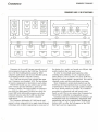
CRDMEMCO AND S-lDO STRUCTURES
_«<'" '''''''''',.
r······..···············..·..··..········..·············..·..··························..
···1
"
r···················,
I l~·J II
I
!
I
I
!i
~
~Ul"
i
i:
I
I
I!
!
i:
,~
i
i
I
I
L.......... ....................................•.............•.......•.. ....._....JI
j
:
L....... .......J
'"'~,. ,,"o....
.............................................J
, .., 00'
'0"""""
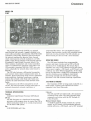
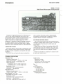
Cromemco is the world"s largest manufacturer of
microcomputers based on the S-100 bus. The 5·100
bus is the best building-block system for OEM
computer applications and the most nexible system
for designing modular computer systems.
The S·100 bus structure was invented the same
year Cromemco was founded, 1975. The bus allows
all system components to interrelate to each other.
With $-100 boards you can achieve your system
goals with the greatest efficiency, speed and
economy of design. The large number of connector
pins (100). the high speed (10 MHz) bus clock. the
large (16M byte) addressable memory and other
technical features make the $-100 bus ideal for
industrial. business. and scientific computer
applications.
The Cromemco philosophy of S-100 boards and
support system components is to apply state-of-the-art
technology and excellent engineering to every part of
<0"'. ....,.,,,
the design. As a result, our boards are efficient. high
quality products that are easy to use.
In order to retain high speed operation while
avoiding noise problems. we use a special groundplane design in all our boards. For every $-100 bus
signal line we have added a ground line. This cuts RF
crosstalk. noise. and the errors these can cause.
Since Cromemco's system level products use the
$-100 bus, the board products have a proven record
of performance. We have very high quality standards
for every board product we produce. It is standard
procedure to extensively test and burn-in every
board we sell. This is one reason why Cromemco has
rated first in reliability on independent surveys.
Cromemco also has extensive lines of software and
development tools and established. dependable field
engineering and service organizations. Besides our
factory staff. we offer the full support of the TRW
third party service organization.
MICROCOMPUTER BOARD LEVel PRODUCTS
CENTRAL PROCESSOR UNIT BOARDS
CENTRAL PROCESSOR UNIT BOAROS
Cromemco
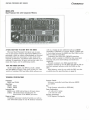
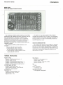
MODEl DPU
Dual Processor Unit with Companion Memory
A FAST. EASY WAY TO START WITH THE 68000
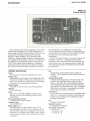
The new Dual Processor Unit gives you an easy
way 10 get started with the impressive 68000 microprocessor. which is widely acknowledged as the most
powerful of the new processors. It has 32-bil wide
internal architecture. 24 address lines allowing it to
address 16 megabytes. 56 main instruction types. five
main data types. and 14 addressing modes.
8·BIT AND 6BOOO SOFTWARE
As the name implies. the DPU has both a UOA
and the 68000 on board. This gives access to a wide
variety of existing CP/M and other 8-bit software as
well as a family of new software such as a 68000
Assembler. FORTRAN 77, Pascal, BASIC. COBOL and
C. Switching between the 68000 and the UOA on the
DPU is software-controlled.
Cromemco also offers the CROMIX operating
system. which is similar to UNIX but has even more
features and gives multi-tasking and multi-user
capability.
Present cllstomers can field-upgrade their
Cromemco systems to usc the DPU and still be able to
run their present software with the UOA on the
DPU.
RAM Memory units for usc with the DPU are also
available (see the specHicalions on page 9).
TECHNICAL SPECIFICATIONS
Processors:
68000 and L80A
Clock Rate:
68000: 8M Hz
L80A: 4MHz
Instruction Set
68000: over 1000 instructions in 56 main types
UOA: 158 instructions including the 78
instructions of the 8080A processor
Power·on Jump:
Cromemco processor standard system. as well as
user selectable jumps to any 4K memory boundary
Processor Control:
Software controlled switching between 68000
and Z.80A
Bus:
5-100 (Jumper selectable to IEEE-696)
Power Requirements:
+ 8 volts @ 2.0 amps
:2; 18 volts not used
Operating Environment:
0-55 degrees Centigrade
Cromemco
CENTRAL PROCESSOR UNIT BOAROS
MODEL ZPU
Central Processing Unit·
Cromemco's ZPU is an 5-100 bus compatible CPU
(Central Processing Unit) which uses the powerful
Z·80A microprocessor. The ZPU has an advanced sel
of features designed to increase total system
computing power. Most importantly. the ZPU
operates reliably at a 4 MHz clock rate-twice the
speed of most other microcomputer systems. The ZPU
also offers power-on-jump capability, an onboard
wait slate generator, optional independent selection
of Ml wait states, address mirroring circuitry, a
parallel printer porI, and priority interrupt
capability.
4 MHz CLOCK RATE
The ZPU lets you choose either a 4 MHz or 2 MHz
crystal-controlled clock rale. The clock rate is
factory wired for 4 MHz and can be optionally
jumpered for 2 MHz operation.
POWER· ON MEMORY JUMPS
With power turn-on. the ZPU will jump to any
desired 4K boundary in memory. No switch flipping is
needed to begin a program.
POWERFUL INSTRUCTION SET
The instruction set of the Z-80A contains 158
instructions. including the 78 instructions of the
8080A.
INTERRUPT CAPABILITY
The ZPU provides priority in/out daisy chain for
the printer port. The board also provides interrupt
and interrupt enable LEOs.
TECHNICAL SPECIFICATIONS
Processor:
4 MHz version of the Z-80A
Clock Rate:
4 or 2 MHz (jumper selectable)
Instruction Set:
158 instructions including the 78 instructions of
the 8080A processor
Power·On·Jump:
Jumper selectable (factory shipped at COOO)
Power·On·Jump locations:
16 locations. jumper selectable
Interrupt Structure:
Priority inlout daisy chain for printer porI.
Interrupt and interrupt enable LEOs.
Bus:
S-100
Power:
+8 volts@ 1.1A
18 volts not used
:l:
Operating Environment:
0-55 degrees Centigrade
CENTRAL PROCESSOR UNIT BOAROS
Cromemco
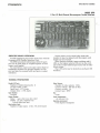
MOOEl SCC
4 MHz Single Card Computer
A COMPlETE 4 MHz COMPUTER
The Single Card Computer (SeC) brings the power
of the Z-80A and the flexibility of the S-100 bus to
the dedicated computer environment.
This card was designed to get your application up
and running fast. It offers 4 MHz operation, up to BK
bytes of on-board 2716 PROM, and lK byte of stalic
RAM memory. Interfacing is easy through the RS·232
(or 20 rnA current loop) serial interface with
programmable baud rales to 76,800 baud. This stand·
alone card also gives you 24 bits of bidirectional
parallel liD, 5 programmable timers, vectored inlerrupts, and complete compatibility with all Cromemco
cards.
The sec is a complete computer. Only a power
supply and your PROM software are required for
operation. Yet it can be the core of an expandable
S-100 bus system since additional memory, 1/0, or
even floppy disk drives can be added as the application requires.
MONITOR/3K BASIC
Cromemco's Z-80A Monitor and our 3K Control
BASIC are available in 2716 ROM for use in the
Single Card Computer. With Ihis two-ROM set
(Model MCB216) the SCC can be used
immediately-no other memory or 1/0 is required.
The monitor has 12 commands to aid in program
development. The Control BASIC has 36
commandsffunctions and can directly access 1/0
ports and memory locations as well as call machine
language subroutines.
TECHNICAL SPECIFICATIONS
Processor:
Z-80A
Instruction Set:
158 instructions
ROM Capacity:
8K Bytes located from address 0000 to IFFF
2716 Programmable with 32K Bytesaver
(Model 32KBS)
RAM Capacity:
1K Bytes located from address 2000 to 23FF
RAM TVpe:
4045. Static
Serial I/O Ports:
1/0 levels: RS-232 or 20 rnA current loop
Baud rate: 110 to 76,800 (software selectable)
Parallel Ports:
Input Port: 24 bits
Output Port: 24 bits
Input Load: One TTL equivalent
Output Drive: 20 TIL loads
Interval Timers:
Number of timers: 5
Timer range: 0-16.32 milliseconds (software
selectable)
Timer resolution: 64 microseconds
Vectored Interrupts:
Number of restart locations (Z-80A mode}: 65,536
UART type:
5501
Bus:
S-100
Power Requirements:
+ 8 volts at 1.4A
+ 18 volts at 70 rnA
-18 volts at 25 rnA
Operating Environment:
0-55 degrees Centigrade
MICROCOMPUTER BOARO LEVEl PROOUCTS
MEMORY BOAROS
Cromemco
MEMORY BOARDS
MODEl 16KZ
16K RAM Card with Bank Select
(
10
fAST. EXPANDABLE
The t6KZ is the fastest 16K RAM card available.
and it is expandable to a half Megabyte with Bank
Select. It will operate al 2 or 4 MHz with no wail
slates.
This memory can be plugged inlo any single user,
Z-80A based computer system.
MEMORY BANK SELECT
Memory Bank Select is a feature incorporated on
Cromemco memory boards Ihat allows the expansion
of memory-space beyond 64K bytes. With bank select.
memory space may be organized into 8 banks of 64K
bytes each for a total of one-half Megabyte of
memory.
Each memory board may reside in one or more of
the 8 possible memory banks. An 8-position DIP
switch on the board is used to select each of the
banks in which the board resides.
The active bank or banks of memory are selected
under software control. Output port 40H is dedicated
to this function. Each of the 8 bits of data of output
port 40H is used to turn the corresponding bank of
memory on or off. A "1" in the corresponding bit
position will turn on the memory bank. A "0" will
turn it off. All circuitry required to detect the output
of port 40H is included on the memory card itself.
TIME SHARING
Bank select also permits the implementation of
time-sharing systems with a minimum of software
overhead-up to 6 users can use the system simultaneously with each user confined to a particular
bank of memory.
TECHNICAL SPECifiCATIONS
Memory Capacity:
16K bytes
Memory Type:
4050·2 RAM
Memory Access Time:
200 nanoseconds
Wait States at 2 MHz:
None required
Wait States at 4 MHz:
None required
Bus:
5-100
Power Requirements:
+ 8 volts @ 0.8A
+ 18 volts @ 0.5A
- 18 volts @ 10 rnA
Operating Environment:
0-55 degrees Centigrade
MEMORY BOARDS
Cromemco
MODEL 64KZ
64K RAM Card with Extended Bank Select
This 64K byte RAM card is fast and very
expandable.
The Model 64KZ is organized as Iwo 32K blocks of
memory. Each block can be placed either in highmemory space (address 8()()()"FFFF) or low-memory
space (address OOOO·7FfF).
Each blod: can further be placed in any of 8
dinerent memory banks. Address and bank assignment of each 32K block is switch selectable.
Another feature is thai each 32K block can be
independently switched 10 be selected or deselected
arter reset.
EXPANDABLE TO 512K
With our Bank Select fealure you can expand
memory space from 64K 10 SI2K in eight banks. (See
page 10 for a discussion of BANK SELECT.)
The 64KZ is fully tested to be compatible with all
Cromemco UO based products.
TECHNICAL SPECIFICATIONS
Memory Capacity:
64K bytes
Memory Type:
4116 RAM
Memory Access Time:
150 nanoseconds
Wait States at 2 MHz:
None required
Wail States at 4 MHz:
None required
Bus:
5-100
Power Requirements:
+ 8 volts @ 0.6A
+ 18 volts @ 0.2A
Operating Environment:
0-55 degrees Centigrade
Cromemco
MEMORY BOARDS
MODEL 256KZ
256K RAM Card
Cromemco's 256KZ RAM card is an S-100 bus
compatible 256K byte read/write memory board. This
board is ideal for use with Cromemco's CROMIX
multi-user, multi-tasking operating system.
In horizontal bank select mode. the 256KZ appears
10 be four 64KZ banks of memory. The 256KZ also
implements the extended addressing capabillty
required to utilize the full addressing power of the
Cromemco DPU processor board. The 256KZ also
incorporales a-bit and 16·bit read/write operations in
accordance with the IEEE-696 standard in order to
further enhance the throughput of 16-bit systems.
Extensive use of LSI and VLSI components reduces
power consumption and increases reliability.
TECHNICAL SPECIFICATIONS
Memory Capacity:
256K Bytes
Memory Type:
4164-15 T2
Wait States:
None required (except during CROMIX
ini tializa tion)
Memory Address Capabilities:
CROMIX-Iype bank switching and 24-bil extended
addressing
Data Path:
S-IOO compatible (IEEE-696) B/16-bil data
read/writes
Bus:
S-100
Power Requirements:
BV @ 900 rnA
Operating Environment:
0-55 degrees Centigrade
Gromemco
MEMORY BOARDS
MODel MCU and MODel 51ZMSU
Memory Controller Unit and Memory Storage Unit
For use with the OPU, Cromemco offers a 512
kilobyte RAM memory unit. This unit works under the
control of a new Memory Controller Unit (MeU)
which supports either byte or word-width operation.
The Memory Controller Unit can control up to four
Memory Storage Units-a lotal of 2 megabytes of
RAM using the 512 kilobyte {512MSUj unit.
A special feature of the memory unit is its built-in
error checking and correction capability. Tn concert
with this capability the Memory Controller Unit has
TECHNICAL SPECIFICATIONS
Model MCU
Support Capacity:
Up to four M5U memory cards
Address Space:
16 Megabytes
Bus:
S-100, (IEEE-696) compatible
Power Requirements:
+ 8 volts @ 1.5A
± 18 volts not used
Operating Environment:
0-55 degrees Centigrade
an error-logging feature which stores the location of
errors encountered and identifies the particular MSU
that had the error. This feature is very helpful in
system diagnostic and maintenance work.
For error checking and correcting, the memory unit
is designed to use 22 bits to encode each 16-bit word.
A modified Hamming code is also used which allows
transparent detection and correction of single-bit
errors and detection of double-bit errors.
Model 512MSU
Memory Capacity:
256K by 22 bits: 512K bytes
Memory Type:
64K dRAMs: 150 nanosecond access time
Bus:
5-100. (IEEE-696) compatible
Power Requirements:
+ 8 volts @ 1.5A
Operating Environment:
0-55 degrees Centigrade
Cromemco
MEMORY BOAROS
MOOEL 32KBS
32K BYTESAVER Memory Boord with 2716 PROM Programmer
32K BYTESAVER PROGRAMS THE
HIGH DENSITY 2716 PROM
The 32K BYTE$AVER is an $-100 memory board
and PROM programmer which uses the 2716
2-Kilobyte PROM.
Cromemco's 32KBS card has a full 32-kilobyte
capacity of non-volatile storage for those ROMintensive applications.
The user also gets the convenience of an on-board
2716 programmer.
The new 32K BYTESAVER holds up 10 sixteen 2716
PROMs. Switches are provided to:
Protect and unproteci PROMs individually or in
groups for programming
Shadow ROM socket pairs (allows external RAM
10 overlap portions of ROM address space)
Select card address
Control the powerful Bank Select and DMA INOUT features.
NO SPECIAL SOFTWARE NEEDED
A simple. one-time write of the desired data into an
erased PROM with the on·board programmer turned
on is all that is required to store information Quickly
and permanently.
TECHNICAL SPECifiCATIONS
Memory Capacity:
32K bytes
Memory Type:
Intel 2716 PROM (single voltage version) or
equivalent
Memory Access Time:
450 nanoseconds
Wait States at 2 MHz:
None required
Wait States at 4 MHz:
One per machine cycle
Bus:
5·100
Power Requirements:
+ 8 volts @ 2.1A. max.
± 18 volts not used
Operating Environment:
0-55 degrees Centigrade
MICROCOMPUTER BOARD LEVEL PRODUCTS
INPUT/OUTPUT BOARDS
Gromemco
INPUT/OUTPUT BOARDS
MODEL lOP
110 Processor
MULTI-PROCESSOR CAPABILITY
With this new 110 Processor the user can have
multi-processor capability in a S-100 bus system.
The new Model lOP is a lrue singll?Csrd process
controller-one that has a fast Z-80A processor. 16K
bytes of RAM, and up to 16K bytes of PROM
capacity.
The lOP interfaces to the S-loo host processor by
means of simple "input" and "oulpuf' instructions.
SATELLITE PROCESSOR
The lOP can be used either alone or with other lOP
cards as a satellite processor on the $.100 bus.
Or the lOP can process 110 channels and interface
10 other devices such as the Cromemco QUADART
through the Cbus connector on the top edge of the
card.
The lOP is an advanced development that brings a
new dimension of computer architecture to
Cromemco computer systems.
TECHNICAL SPECIFICATIONS
Processor:
4 MHz Z-80A
Instruction Set:
158 instructions (including the 78 instructions of
the 8080A processor)
ROM Capacity:
16K bytes positioned starting on any 2K boundary
(selectable by bipolar PROM)
ROM Type:
Intel 2716, 2732 or equivalent
RAM Capacity:
16K bytes positioned starling on any 2K boundary
(selectable by bipolar PROM)
Standard Address Configuration:
PROM - 000 to 1FFFH
RAM - 4000H to 7FFFH
RAM Type:
4116
Host Interface:
5-100 bus input-output ports
Peripheral Interface:
Cbus
Ml Wait State Generation:
0-1 wait states jumper wire selectable
Power Requirements:
+ 8 volts @ 1.5A
+ 18 volts @ 100 rnA
- 18 volts @ 30 rnA
Operating Environment:
0-55 degrees Centigrade
Cromemco
INPUT/OUTPUT BOAROS
MODEL DDRT
OUADART Serial Communications Interface
17
SIMULTANEOUSLY INTERfACES UP TO
fOUR SERIAL CHANNELS
This versatile new QUADART serial communications interface card offers the power to satisfy
virtually any high-speed data communications
application.
The QUADART card is designed to operate with
the 110 Processor (Model rOP). It includes four
independent serial channels. each supporting
Asynchronous. Synchronous byte mode (Bisync), and
Synchronous bit mode (SDLe) protocols with complete
handshaking for modems. Serial prolocol is softwareselectable for each channel.
The unique loopback feature gives the capability to
connect data from any channel to any other channel.
to connect data from any modem to any other modem.
or to use any modem/channel combination for diagnostics and selftes!.
Baud rates for each may be software-selected from
o to 300K baud [asynchronous to 19.200 baud).
TECHNICAL SPECIFICATIONS
Serial Channels:
Serial protocols:
Asynchronous Byte
Synchronous Byte [Bisync]
Synchronous Bit (SDLC)
Modem handshaking
Number of channels: 4
Diagnostics: Channel-to-channel diagnostic loopback capability (input/output channels software
selectable)
Asynchronous Baud Range:
o to 19,200 baud {software selectable)
Synchronous Baud Range:
o to 300K baud (software selectable)
Interval Timers:
Number of timers: 4
VECTORED INTERRUPTS
The QUADART also supports the powerful
internally-prioritized vectored interrupt structure of
the Z.80A microprocessor which has become a
trademark of Cromemco interface cards.
INTERVAL TIMES
The QUADART has real-time clocking capability
with four interval timers each having periods as
small as 4.00 microseconds. Up to three timers can
be cascaded to provide a 1.000-second time interval.
The software-selectable time range of each timer is
o to 16.384 milliseconds.
C·BUS
The control for the QUADART is from the C-bus
provided by Cromemco's powerful 110 processor
computer. Model lOP. The rop interfaces between
the S-100 bus and the C-bus and can support up to
four QUADARTs with full interrupt capability.
Timer range: 0 to 16.384 msec (eascadable to 1.0
second. software selectable)
Timer resolution: 4.0 microseconds
Vectored Interrupts:
Number of restart locations (z.aOA mode): 65,536
Prioritization of serial channels and timers:
Internally prioritized
Prioritization for multiple QUADARTs:
daisy-chaining
Serial Channel Type: zaO·SIOf2
Parallel Channel Type: ZaO-PIO
Timer Type: zaO-CTC
Interface: C-bus
Power Requirements: + a volts @ 1.5A
+ 18 volts @ 100 rnA
- 18 volts @ 100 rnA
Operating Environment:
0-55 degrees Centigrade
INPUT/OUTPUT BOARDS
Cromemco
MODEL CNI
C-NET
The Cromemco Network (eNET) is a network
specification built around a rugged. shielded twinaxial cable and military specification MIL-STD-1553B.
Cromemco's eNI C-NET Interface board interfaces
the network medium (Ihe physical data channel
which interconnects network stations) to a 4 MHz
Z-BOA, single board computer with program storage
[Cromemco's Input/Output Processor board). The
CNrs isolation transformer and crystal controlled
clock are optimized for operation with C·NET. The
eNI provides a standard 500 kHz C-NET data rate
and is adaptable for network data rates from 0 10
880 kHz.
The eNI also features a differential transmiller
and receiver which rejects common mode noise. In
addition. phase locked loop clock recovery minimizes
noise sensitivity. Isolation transformer coupling
isolates the network cable from node faults and
protects the node electronics from network cable
faults.
Bit protocol on the CNI is managed by an LSI
circuit. The hoard provides vectored interrupts on
network characters. network conditions. or
programmable timers. Two uncommilled general
purpose timerfcounter circuits with extended timing
intervals are also provided. The CNI includes an
RS-232 serial port for use with a local terminal.
OPERATING MODES
The CNI hoard includes four programmable
counter and timer circuits and an lOP to RS-232
interface (75 to 19.200 baud). This means that a
complete. low cost. C-NET station can be built using
only a power supply. a CNI board. an lOP board. and
a CRT (or any other RS-232 equipment). At the other
end of the spectrum. a single lOP can manage a CNI
board to function as an intelligent. distributed
processing network task for the host 5-100 bus
processor. with full vectored interrupt capabilities.
A NETWORK STANDARD
The Cromemco C-NET is being made available as a
multi-vendor. industry-wide standard for microcomputer Local Area Networks.
TECHNICAL SPECIFICATIONS
C·bus use:
Controller:
The CNI and lOP are linked with a 50 conductor
overhead C-bus cable. The CNI exchanges data.
commands and status with the lOP through 10
C-bus 110 ports.
Minimum Network Station:
A complete network station consists of a power
supply. an lOP board with downloaded network
station software. a CNI board. and a CRT terminal.
Cromemco Input/Output Processor (lOP] Board
lOP Use:
The lOP functions as a distributed 5-100 Z-BOA
processor with program store to control the CNI in
either stand-alone mode or as a task pre-processor
for the host 5-100 system.
Bus:
5-100 (IEEE-696) and C-hus
INPUT/OUTPUT BOARDS
Cromemco
Network Interface:
Z-80 SID serial channel A manages the lOP 10
network interface. The network channel is
operated in SOLe Mode (Byte Synchronous Mode
may optionally be used). The network channel may
be either transformer coupled to twin-axial
balanced lines (e-NET bus cable) with a fixed data
rate, or TTL coupled to unbalanced lines with an
externally controlled data rale.
Network Modulation:
Synchronous digital. phase encoded
NetwOIk Data Rate:
C-NET: 500 KbpS:2: .001 %
Altmode: Q-880 Kbps. clock externally supplied
RS·232 Interface:
z-aO SID serial channel B manages the lOP to
RS-232 interface. The RS-232 channel is operated
in Asynchronous Mode with a software defined
data rate from 75 to 19,200 baud. SID B controls
modem circuits OTR. DCD, crS. and RTS. Both
DTE (CRT) and DCE (Modem) style connections are
provided.
Counters/Timers:
A Z.80 erc supplies four programmable counterl
timer channels.
Intenupts:
Both the Z-80 510 and the Z-80 ere may be
programmed to generate prioritized. maskable and
vectored &80 1M2 interrupt requests to the lOP.
lSI Device Types:
One &80 SIO (Serial InputJOutput)
One Z-80 CTC (Counter Timer Circuit)
Power Requirements:
+ 8 VDC @ 1.2A (max)
- 18 VDC @ 150 rnA (max)
+ 18 VOC @ 500 rnA (max)
Operating Environment:
0-55 degrees Centigrade
Cromemco
INPUT/OUTPUT BOAROS
MODEL CSP
Serial/Parallel Interface
•
20
~ ...
. _.
' - _ ...." ' :
~-:T'.J !.~.
~
~
"
'f"!
: '.
-
.
,......
ou.-z._
.....
r.I'"
n.,
_'.'I'!I""I!"""!lJlI!J!I~"3
.
..:
'i'
~.
•.
,fl'" ..... ,.'..
!'!. rt>..... ,M'I'~~:.fl•.~:.~.~~
.~: :-'·~~~:"1·1,.!~2":~
jIl:tI:
I: ·....,·D~·
'»:'! ' I'.,~.
er'I-,,:'~
~.:: ;v:
: :.; :lla:!l:• : \: : :.
:,l. i•
:.~:., ~n
-III!:
.
: ,'I.
.i.l~
0<.....- . . _
~-.:~
}J1:
OC.
lOt
j
-p."
..,,
•.,' •.- ', "';"·1'
'll'"
'''ll'
'~ . l'o'
"",'. I'
• , •••
• , • •'II'''~''''''''''
\- • •
= ,• "•I
" .-•. . . - _ •. : :_~ ; : : ~ :~: :~: : : : ': : : '~.' . ','~'. l··~·
·, I~~"'''''''''''i .,".
'.' -" 'U.. '-'
·~·.·..... ·.·u·
~ . ~.'--~ .. ,,~.
0'" .... '~ ,....
...•
O'(r1!"
'~. ,_.....
"~,.".~
• ~.
oj,
, • • •"
,
•
'I!"";~'nrn Or: 1i'.'·1nl~··'"·~'~";: ,.,.:,": ~'''':'mr'''I'
=_. :•
"1
'" ~ ,,,1<1, .""•-•-• ,. •:+. ,,~.....
~. -.~. ......
. Ji£~. ;:
•
•••_....
"Ie>'~' F·.,~.~·.·--_!1!._",-..t,
'l"":
""". ; ,,. . ."'. •• 'i, . .l. ,if.,.
..-~.."i!." •
~.,.~
•
l""'·.·
'i
n
o-'.'"
~~~.~h:l:n:I:;I:::~I:*:~;·i::: ',.,
,.---~\'"'.:...,;~;: "~~:,:,:I·:.dl:t:::.: I":: ::1.:
•·
l
.........
,..-t\
~
".
~
.
~,::.::
~
, : , - . : . ; - • .0.;:;,,;-;,
\~ :~":__
;
-
•
,.'/,."'"
'. I
uo
:::7.0_.-:'
:fm..:
~
t;:
.-~,. .,....~.-
~t~
:.:,,~
_"[.
Fi: lh: I' " "
:r;; ••
:~f1";""'"
\".~
il.i' il.i··:·········
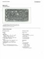
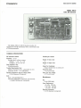
This card interfaces to the C-bus of our 110
Processor card and provides general-purpose 110
capability as well as serial communications
capability.
The card has three parallel If0 ports and two
serial porls.
Two of the three parallel ports are TTL-buffered
for general usage. The third port is buffered by a
FIFO to permit inpulling and outputting of rapid
bursts of data. For example. up to 16 bytes can be
TECHNICAL SPECIFICATIONS
CSP Controller:
Cromemco InputfOutput Processor [lOP) board
Parallel Interface:
Compatible with Cromemco Model TDS 9 Track
Tape Drive
Parallel Output
Data: 8 bits wide plus an End of Transfer bit; 16
by 9 bit FIFO buffered: approximately 200K
bytes/second maximum continuous [Z-80A 110
Block Move). approximately 10M bytes/second
maximum burst (FIFO limited].
Parallel Input:
Data: 8 bits wide; 16 by 8 bit FIFO buffered:
approximately 200K bytes/second maximum
continuous (Z-80A 110 Block Move). approximately
10K bytes/second maximum burst (FIFO limited].
General Purpose: 16 status bils in two input bytes:
vectored maska ble C-bus interrupt requests
generated on software selected bit states.
Termination: TrL levels: 220f330-ohm
terminations on all data and status lines.
Cartridge Modes:
Serial Asynchronous. Synchronous Byte (Bisync)
and Synchronous Bit (SDLCj under the
management of a 2-80 SIO device: vectored
'~II
I,l
,~:
;":
.1.:' ~
•
'!I:: 'il: 'j!:
stored in the FIFO at 110 clock rates up to 10
megabytes/second.
The two serial porls are single full duplex serial
channels that facilitate communications applications.
One port is for synchronous communication (SDLC or
HDLCj at rates up to 800K bits/second.
The second serial port is a serial RS-232C interface for asynchronous communication. It has a
programmable data rate of up to 9600 bitsfsecond.
maskable C-bus interrupt requests generated on
software-selected status comlitions.
Cartridge 110:
Maximum data rate approximately 800
kbits/second: TxC and RxC clocks supplied by
Cartridge peripheral: ITL levels with 220/330-ohm
terminations on input lines.
Terminal Interface:
RS-232C DTE connection
Terminal Modes:
Same as Cartridge Modes above although
Asynchronous Mode would typically be selected.
Terminal 110:
Maximum data rate 9.600 bits/second: TxC and
RxC supplied by an on-board timer with software
selectable bit rate: RS-232C levels: circuits RTS.
CTS. DSR and DCD may be used either for modem
control or for general purpose RS-232C level I/O.
Bus:
Standard-l00 (S-100) Cromemco Bus (C-bus)
Power Requirements:
+8 VDC @ 1.5A (max)
+ 18 VDC @ 25 rnA [max]
- 18 VDC @ 25 mA (max]
Operating Environment:
0-55 degrees Centigrade
Cromemco
INPUT/OUTPUT BOAROS
MODEl 0+7A I/O
Multi-Channel Microcomputer Analog Interface
21
Cromemco's high performance D+7A ItO gives you
a way to get analog information into and oul of a
microcomputer easily, quickly and inexpensively. The
Model D+7A offers 7 channels of B-bit analog-todigital conversions (10 input analog data 10 the
computer): 7 channels of digital-ta-analog conversion
(to output computer data in analog form): an 8-bit
parallel ItO port to input and output data in digital
form: and a fast conversion time of 5.5 microseconds.
A MUlmUOE OF USES
The O+7A makes it easy to use a computer for such
jobs as process control, digital filtering, oscilloscope
graphics. speech recognition. and speech and music
synthesis.
The O+7A lets you input and output analog data
TECHNICAL SPECIFICATIONS
Analog Input Ports:
Number of input ports: 7
Input voltage range: - 2.56 to + 2.54 volts
Input bias current: 2 microamps max.
Input impedance:
20 Megohms .001 F, 1 kHz sample rate
2 Megohms .001 F. 10 kHz sample rate
Resolution: 8 bits
Conversion time: 5,5 microseconds
Accuracy: + 20 millivolts
Analog Output Ports:
Number of output ports: 7
Output voltage range: - 2.56 to + 2.54 volts
Output Impedance: 0.25 ohm
Maximum load current: 1.5 rnA
Resolution: 8 bits
Conversion time: 5.5 microseconds
Accuracy: + 20 millivolts
Drift rate: Less than 10 mVfsec at 25 C
with a vareity of devices: such as measurement
instruments. machine tools. transducers. control
systems. motors, recorders, and plotters.
NO FURTHER SOFTWARE NEEDED
The D+7A ItO plugs directly into Cromemco microcomputers. Analog signal range is from - 2.56 to 2.54
volts (20-millivolt increments) on both input and
output sides.
Simple Input and Output instructions initiate AID
conversion and read the ensuing 8 bits of data in or
out. No further software is required. During conversion the D+7A holds down the computer "Ready"
line.
Each O+7A includes a connector to connect to the
8 input and 8 output ports.
Parallel I/O Port
Input port: 8 bils
Output port: 8 bits
Input load: One TIL equivalent
Output drive: 10 TIL loads
Bus:
5-100
Power Requirements:
+ 8 volts @ OAA
+ 18 volts @ 30 rnA
- 18 volts @ 60 rnA
Operating Environment:
0-55 degrees Centigrade
Cromemco
INPUT/OUTPUT BOAROS
MOOEl OAC12
12·Bit DIA Converter
22
The Model DAC-12 orA I/O board provides two
independent channels of 0 to A conversion with a
conversion time of 5 microseconds.
TECHNICAL SPECifiCATIONS
CIA converter section
Parallel port section
Resolution:
Number of Ports;
2
Output Port Handshake:
Output strobe line on each pori
12 bit
Analog Output:
Bipolar voltage: + lOV. + 5V, + 2.5V
Unipolar voltage: 0 to 5V, 0 to lOV
Impedance: 0.05 ohm typical
Conversion Speed lsettling time to + 0.0 1% FSRl:
+ tOV output; 5 microsec.
Accuracy:
Offset error/gain error: adjustable to zero
Linearity error: + 1/2 LSB (max)
Operating temperature range lna missing codes):
Olo50C
Drilt:
Gain :r 7 ppm/degrees Centigrade {max.)
Linearity ± 20 ppm/FSR/degrees Centigrade
Output Port Drive:
7 l~rL unit loads
Sense line Input loading:
4 TIL unit loads
Miscellaneous
Bus:
5·100 (1£££·6961
Power Requirements:
+ 8 volts: 350 rnA
+ 18 volts: 120 rnA
- 18 volts: 100 rnA
Operating Environment:
0-55 degrees Centigrade
Cromemco
INPUTIOUTPUT BOARDS
MODEL Aoel2
12·Bit AID Converter
2:J
The Model ADC·12 AID IIO board provides 16
channels of A-tOoD conversion with a conversion time
of 30 microseconds.
TECHNICAL SPECIFICATIONS
Ale converter section
Resolution: 12 bit
Analog input voltage ranges;
Bipolar: + 2.5, + 5. + 10
Unipolar: 0 to 5. 0 to 10
Data Acquisition Time:
30 microseconds
Transfer Characteristics Error:
Offset error/gain error: adiustable to zero
Linearity error: + 1/2 LSB (max)
Operating temperature range {no missing codes}:
o to 50 degrees Centigrade
Drift:
Gain ± 30 ppm/degrees C
Linearity (monotonic operation guaranteed];
± 3 ppmfFSRfdegrees Centigrade
Parallel port section
Number of Sense lines:
4
Number of Output Ports:
2
Output Port Handshake;
Output strobe line on each port
Output Port Drive:
7 TTL unit loads
Sense line Input loading:
4 TTL unit loads
Miscellaneous
Bus:
5·100 (1£££·696)
Power Requirements:
+ 8 volts: 250 rnA
+ 18 volts: 120 rnA
- 18 volts: 100 rnA
Operating Environment:
o to 55 degrees Centigrade
Gromemco
INPUTIDUTPUT BOARDS
MODEl WDI·II
Winchester Disk Interface
The WDI provides an interface between the system
5-100 Bus and a hard disk drive. The wor circuits.
together with the operating system. formal and
control data transfer between the system main
memory and the disk surface media. High speed
memory-to-memory data transfers may be made
between addressed locations in system main memory.
The extended address function allows extended
addressing using address-a8-data information
received from the 5-100 bus.
USER SELECTED OPTIONS
There are Iwo types of user selected options
available for the WDI. Inlerhoard functions may be
selected using interconnecting cables. and intra board
functions may be selected using onhoard jumpers.
The inter board options set up priorities between
boards for system bus requests and system
interrupts. WDI bus requests are generated by the
Address Generator (DMAJ. WDI interrupts are
generated by the Address Generator. eTC (Counter'
Timer Circuit). and the PIO (Parallel Input/Output)
controller circuits.
SYSTEM COMPATIBllI"iY
The WDI is designed for use with all Cramemca.
5-100 Bus systems. All Cromemco Hard Disk Drives
are compatible with the WDI.
TECHNICAL SPECIFICATIONS
Modes and Functions:
Hard Disk Data Transfer
Memory-to-Memory Data Transfer
Extended Addressing
Disk Drive Compatibility:
Cramemco Hard Disk Drives
Disk Drive Capacity:
4 Maximum
Bus:
5-100
Power Requirements:
+ 8 volts @ 1.4A
-18 [email protected]
Operating Environment:
0-55 degrees Centigrade
Cromemco
INPUT/OUTPUT BOAROS
MODEL 64FDC
Floppy Disk Controller
The Cromemco Model 64FDC floppy disk controller
board provides a complete system for noppy disk
operation including serial 110 for an RS-232 terminal.
a pre-programmed Read Only Memory with system
bootstrap and diagnostic routines. and full readl
write/format capability for any combination of singleor double-Sided. single- Of double-density five inch or
eighl inch floppy disk drives. The Model 64FDC
normally handles up 10 fOUf drives in a daisy-chain
configuration. Up 10 sixteen drives may be connected
if the drives decode the fOUf drive select lines.
An important feature of the 64FDC is its support of
included in the Cromemco System Three. The Model
64FDC includes standard write precompensation to
ensure high reliability on the inner tracks of a wider
variety of eight-inch drives.
The 64FDC includes a 512 millisecond real time
clock for use with the CROMIX multi-user, multitasking operating system.
The data recovery circuit on the 64FDC uses a
patented phase locked loop to optimize performance
for each size and density diskette. The 64FDC also
provides an upgrade path for using higher data rates
with future generation five-inch floppy disk drives.
the new slimline eight.inch drives such as are
TECHNICAL SPECIFICATIONS
Disk Controller:
Maximum number of 5lf.i" drives: 4
Maximum number of 8" drives: 4
Bootstrap/monilor firmware: 4K byte ROM
monitorfbootldiagnostic
Controller circuitry: MOS LSI
Serial I/O Port:
110 levels: R5-232 or 20 rnA current loop
Low baud range: 110-9600 baud (software
selectable)
High baud range: 880-76.800 (software selectable}
Diskette Format:
Size: 5 1/4" or 8"
Sides: Single or double
Density: Single (FM} or double (MFM}
(software selectable)
Data recovery: analog phase-lock loop
(U.S. Palent 4 319 200)
Write precompensation: Crystal controlled delay
generator
Formatted Disk Capacity:
51A"
8"
243K
Single-sided, single-density
83K
190K
BOOK
Single-sided, double-density
594K
173K
Double-sided, single-density
1216K
390K
Double-sided. double-densily
Interval Tmers:
Number of timers: 5
Timer range: 0-16.32 msec (software selectable)
Timer resolution: 64 microseconds
Bus: 5-100
Disk controller type: 1793-802
UART type: 5501
ROM type: 2332
Power requirements: + 8 volts @ 1.5A
+ 18 volts @ 100 mJ\
- 18 volts @ 100 rna
Operating environment: 0-55 degrees Centigrade
Cromemco
INPUT/OUTPUT BOAROS
MOOEl4PIO
4 Port I/O Isolated Parallel Interface
6
The Cromemco 4PIQ Parallel Interface Card allows
interfacing with complete electrical isolation from the
host microcomputer. Therefore. problems with
ground noise and ground loops can be completely
eliminated in instrumentation. communications, or
process control systems. In addition. potentially
damaging transients can be safely isolated from the
computer system.
The Cromemco 4PIO parallel interface card
includes:
24
16
8
11
1
opto-isolaled input channels
opto-isolaled output channels
relay-isolated output channels
opla-isolated strobefhandshake lines
oplc-isolated reset line
The 4PIQ services these isolated 110 channels
through fOUf parallel, a-bit ItO ports. The addresses
of these 110 ports are switch selectable (in blocks of
four) by means of a switch conveniently located on
the 4PIO interface card.
ISOLATEO CONNECTOR PINS
The isolated 110 channels of the 4PIO are brought
10 four connectors on the top edge of the card. NO
PIN ON ANY OF THESE CONNECTORS IS DIRECTLY
CONNECfEO TO THE COMPUTER CIRCUITRY. Every
active pin is electrically isola led by means of an
apia-isolator or relay.
TECHNICAL SPECIFICATIONS
Parallel 110 Ports:
Number of bidirectional paris: 4
110 port widlh: 8 bils
Number of apia-isolated input ports: 3
Number of opta-isolated output ports: 2
Number of relay-isola led outpul porls: I
I/O Strobe Signals and Reset:
Number of 110 slrobe bits: II
Strobe signal isolation: apia-isolated
Reset line: opta-isolated
Opto·isolated 110:
Number of opt a-isolators: 52
Opta-isolator type: MCT66
Signal levels: 'rrL
Relay Outputs:
umber of relay outpuls: a
Contact type: SPOT
Conlact voltage: 28V (AC or DC)
Contact current: lA
Bus:
5-100
Power requirements:
+ a volls @ 2.3A
Operating environment:
0-55 degrees Centigrade
Cromemco
INPUT/OUTPUT BOAROS
MODEL BPIO
8 Port I/O Multi-Channel Microcomputer Parallel Interface
2
SIMPLIFIED PARALLEL INTERFACING
Parallel interfacing was never easier than with the
Cromemco BPIO Parallel Interface Card.
The BPIO provides B bidirectional B-bit 110 ports
that can be used singly or coupled together to (orm
longer wurd lengths.
For convenience. input and output status nags for
handshake purposes Bre grouped togelher on one
port and may be accessed with one input or output
statement.
Strobe pulses can be issued after each a-bit
transfer or may be delayed until the proper word
length has been formed.
Other features include 8 sense switches and 8
LEOs on the highest selected 110 port on the card.
and 2 bils of aplo-isolated input and 2 bits of relaydriven output.
The a JlO ports may be located on any a-port JlO
boundary.
TECHNICAL SPECIFICATIONS
Parallel 110 Ports:
Number of bidirectional ports: 8
I/O port width: 8 bits
Input load: 4 TTL loads
Output drive: 4 TTL loads
Input Strobes:
Latched
Output Strobes:
Delay: 1 IJsec after new data valid
Width: 1.5 J.lSec: negative true
I sl robe pulse per port
Opto·lsolator Input:
Number of opto inputs: 2 bits. TIL level inputs
Relay Outputs:
Number of relay outputs: 2 bits
Contact voltage: 2aV (AC or DC)
Contact current: lA
Contact type: 5PDT
Bus:
5-100
Power requirements:
+ a volts @ 1.5A
Operating environment:
0-55 degrees Centigrade
Cromemco
INPUT/OUTPUT BOAROS
MODEl 1R1
TU·ART Digital Interface
26
FAST - SOFTWARE SELECTABLE BAUD RATES
UP TO 76.BOO BAUD
The TV-ART digital interface is a convenient interface to allow coupling to two terminals or other
devices. such 8S line printers or modems.
It has two serial 110 porls. two a-bit parallel 110
porls. and 10 independently programmable interval
timers.
Baud rates are software-selectable from 110 10
76.800 baud.
VECTORED INTERRUPTS
Another special convenience of the TV-ART is its
vectored. prioritized interrupts. It is able 10 support
the powerful vectored interrupt structure of the
Z·80A microprocessor.
INTERVAL TIMERS
The 10 intervallimers have real-time clock
capability; therefore. they offer a wide range of
control possibilities.
Each timer range is from 0 to 16.32 milliseconds
and is software selectable.
See Support System Components Section, page 37,
for information on cables to be used with this card.
TECHNICAL SPECIFICATIONS
Serial I/O Ports:
Number of ports: 2
110 levels: RS·232 or 20 rnA current loop
Low baud range: 100 to 9600 baud (software
selectable)
igh baud range: 880-76.800 baud (software
selectable)
Parallel I/O Ports:
Number of ports: 2
Input ports: 8 bits
Output ports: 8 bits
Input load: One TTL equivalent
Output drive: 20 'rrL loads
Interval Timers:
Number of timers: 10
Timer range: 0 to 16.32 msec (software-selectable)
Timer resolution: 64 microseconds
Vectored Interrupts:
Number of restart locations (8080 mode): 8
Number of restart locations (Z-80A mode): 65,536
Prioritization of TV-ART ports: Internally
prioritized
Prioritization for multiple TU·ARTs:
daisy-chaining
UART type:
550t
Bus:
S-100
Power requirements:
+8 volts @ 1.0A
+ 18 volts @ 80 rnA
- 18 volts @ 40 mA
Operating Environment:
0-55 degrees Centigrade
Cromemco
INPUT/OUTPUT BOAR OS
GPIB
General Purpose Interface Bus
29
This card enables you 10 connect your Cromemco
computer 10 measuring and control equipment that
has an IEEE-48B porI. the communications standard
in instrumentation applications. This allows arrangements such as a computer-operated measuring and
control system to be devised.
The Cromemco CPIB card contains a dedicated
Z-BOA processor along with 4K of RAM and two 2716
sockets that provide for 4K of EPROM. Connectors at
the lop of the card arc for the IEEE-48B interface.
There is also a connection for an external TTL
parallel 1/0 port. Switches select the 110 address
through which the computer communicates with the
card and the address to which the card responds.
The CPIB card can interrupt the host computer
over the S-100 bus with either a software maskable
or nonmaskable interrupt and is equipped with the
Cromemco interrupt priority daisy chain. The
dedicated Z-80A on the card can be interrupted by
the host. the CPIB chip, or the reception of data from
the external input port. On-board priority
determination is fully software defined. employing a
hardware poll of the possible interrupt devices over
a single input port.
TECHNICAL SPECIFICATIONS
IEEEA88 Functions:
C
T.TE. L. LE
SH.AH
DC. DT
SR
pp
RL
Controller with Pass Control
capability
Talker and/or Listener
Automatic Source and Acceptor
Handshake
Device Clear and Device Trigger
Service Request
Parallel Poll
Remote/Local with Remote Lockout
Processor:
Z-80A clocked at 4,000 MHz
ROM Memory:
Socket space for 4K/bytes of 1'1 2516. Intel 2716.
or their generic equivalents (user supplied]
RAM Memory:
4Kfbytes of 9124 (1 K x 4) stalic RAM (included)
S·100 Bus Interface:
Four 6·bit parallel liD ports; the GPIB card may
issue non-maskable interrupt requests to the Host:
the Host may issue maskable interrupt requests to
the card.
GPIB Bus Interface:
The 24 IEEE-486 bus lines interface to a GPIB card
connector.
Utility Interface:
One 8-bit parallel input port and one 6-hit parallel
output port provide a general purpose interface at
a CPIB card connector.
LSI Device Types:
Z-80A CPU, TMS 9914 CPIB Adapter
Power Requirements:
+ 8 VDC @ 1.5A (max)
± 18 volts not used
Operating Environment:
0-55 degrees Centigrade
INPUTIOUTPUT BOAROS
Cromemco
MODEL PRI
Printer Interface
3D
A VERSATILE CARO WITH
TWO INTERFACES ON ONE CARO
With this interface card, It's easy 10 interface
either dot-matrix or full letter printers to your
computer system.
For use with these printers. the PRJ is designed
with two actual interfaces. One uses the "Centronics
parallel" convention and interfaces the Cromemco
Models 3715 or 3703 dot-matrix printers.
The second interfaces the Cromemco Model 33558
leiter Quality printer.
This second interface has built-in ribbon-lift and
ribbon-lowering circuitry 10 free the software
overhead normally required for this function.
Each of the two interfaces has an individual cable
connection on the top edge of the card.
The Cromemco PRJ card also includes full interrupt
capability for use in multi-user systems.
TECHNICAL SPECIFICATIONS
Output Port Addresses:
54. SA. 58. 5C
Input Port Addresses:
54. SA
Alternate Port Addresses:
Optional DIP switch
Software Support:
Cromemco COOS. CROMIX
Bus:
5-100
Power Requirements:
[email protected]
Operating Environment:
0-55 degrees Centigrade
INPUT/OUTPUT BOARDS
Cromemco
MOOEL CTI
Terminal Interface
,1
The Cromemco CTt Terminal Interface is an S.IOO
based board designed for use with Cromemco's C·l
video display and CKB series keyboard. The en card
contains all the display electronics for this full·
featured "smarl terminal," Four character sets
(American, American Bold. Graphics. and Scientific)
are supplied in 8K of ROM on the en. The ROM can
be changed to accommodate special character sets.
The en can also be used to emulate a Cromemco
3102 CRT terminal. Through ils $·100 bus interface.
the en has an effective dala transfer rate of more
than 25.000 baud. An additional serial port for
driving auxiliary devices. such as a serial printer, is
also included on the board. On-board RAM and CPU
provides full screen buffering and editing
capabilities.
The C'TI Terminal Interface card also features the
Intel 8275 controller. a high performance DMA
Controller. and a versatile UART (for keyboard and
serial printer use). For communications to hosl, the
board provides standard 5-100 DATA and STATUS
port protocols.
TECHNICAL SPECifiCATIONS
Format:
Bell:
80 characters by 25 lines. Optional status line.
Character Type:
Alphanumeric and Graphic. 512 displayable ASCII
characters within B x 9 dot matrix. Descenders or
lower case characters. Alphanumeric and Graphic
characters can be mixed on the screen.
Character Display:
Standard or inverse video. User Programmable.
Tabulation:
Fixed TAB stops
Cursor:
Four types: underline. blinking, underline nonblinking. reverse video blinking. reverse video
non-blinking.
Host Communications Interlace:
S-1OO Bus status and data port
Transmission Rate:
Up to 25.000 baud
Display: (Model C· I)
A standard TSC video monitor with 12" P31
green phosphor non-glare screen. Optional swivel
and tilt stand. All power is supplied by en board.
Connects to CTI board with a single cable. Monitor
back panel has connectors for keyboard. auxiliary
serial porI.
Audible beep from keyboard upon receipt of
control G. The continuous alarm On/Off feature is
included.
Keyboard: (Model CKBAI
A 60-key ANSI-compatible. TTY/Typewriter com-
patible layout featuring auto repeat. two key
rollover. and alpha lock. The keyboard cable is a
4-wire telephone type coiled cord. The keyboard
will operate up to 25 inches from the C-l terminal.
Other features include a programmable keyclick.
repeat rate. and numeric pad mode.
Serial Interface:
Printer interface with busy/ready handshake. Data
sent to C-l is also sent to printer when printer is
turned on from keyboard. No additional printer
interface is required.
Bus:
Standard 100 (S-I00)
Operating Environment:
0-55 degrees Centigrade
Input Voltage and Frequency:
B volts @ .5A
+ 18 volts @ 1.5A
-18 volts @ .tA
MICROCOMPUTER BOARO LEVEL PROOUCTS
HIGH RESOLUTION COLOR GRAPHICS
Cromemco
HIGH RESOLUTION COLOR GRAPHICS
MODEL SOl
Color Graphics Interface
The SDI graphics interface features high resolution
and a wide range of color choices.
It is a fully-integrated way 10 display the memory
content of Cromemco computer systems in beautiful
and meaningful color choices. Use of color and the
high resolution of the image simplify examination or
discussion. Various paris of the scan can be
displayed in any of 4096 colors.
The interface consists of two circuit cards thai
plug directly into any Cromemco computer, without
alteration of the computer. All necessary outputs 10
the monitors are provided by the interface.
The display device is typically an RCB Monitor
used in the industry or available from Cromemco
[Model RGB-13).
HIGH RESOLUTION
The SOl interface can be used 10 display images
with up \0 754 x 482-poinl resolution. This resolution
(
is at least the equal of a high quality broadcast·TV
picture.
COLOR OR B/W
The interface can be used to display an image in
either color or black·and-white-or in both
simultaneously.
In color any 16 colors from a palette of 4096 colors
can be used in the picture. In black-snd-white any 16
shades of gray can be used.
HOW THE sal MAPS
The SOl uses direct memory access to display the
content of a display memory. Each pixel of the
display may be mapped either from one nybble
(4 bits) or one bit of the display memory. The
mapping mode [nybble or bit] is softwareselectable-in fact. part of a picture may be
displayed in one mode and part in the other.
(
HIGH RESOlUTION COLOR GRAPHICS
Cromemco
The display memory may consist of either a 12K or
48K memory.
The combination of mapping modes and memory
result in four basic modes of operation as shown
below:
MOOEL SOl RESOLUTION IHORIZONTAL'VERTlCALJ
IN EACH Of fOUR MOOES Of OPERATION
:15
Display Memory Size
12K
Nybble-Mapped
Bit-Mapped
189
x 121
377 x 242
48K
378
x 242
754 x 482
SOl OUTPUTS
The Model SOl provides three separate analog
output signals to drive the Red, Green. and Blue guns
of a high-quality RGB monitor. The three separate
outputs. rather than one composite output. are used
to preserve the full resolution of the picture.
In nybble mapped operations each 4-bit nybble can
select one of 4096 colors as determined by a mapping
RAM. The contents of the mapping RAM can he
changed dynamically, under software control. by
issuing OUTPUT instructions to the sm.
connector on the top of the memory cards. The cards
plug directly into the Cromemco computer.
The computer resident memory may also be used
as the display memory. although at the expense of
mapping speed. This reduction occurs because the
CPU must suspend operation when the Sol accesses
the resident memory. The result is approximately
55% CPU utilization for a 12K-memory picture and
6% utilization for a 48K-memory picture.
Use of the special two-port memory assures 75% to
100% utilization, depending on the application
software.
TV COMPATIBILITY
The Model Sol also provides all signals required to
serve as input to a colorizer or color modulator in a
TV broadcast studio.
OESIGNEO TO SURPASS TV OUALITY fOR
LONG·TERM APPLICATION
In its high-resolution mode. the SDI displays a
picture having a 754 x 482-pixe[ resolution. This
formal corresponds 10 and is compatible with NTSC
TV systems practice in that 482 lines are normally
displayed in a nominal 525-line system. The 754
points in Ihe horizontal direction give a resolution
equal to or better than that of Ihe vertical direction.
The result of the above approach is thai the highresolution picture displayed using the SDI interface
is al least equal in resolution to a 525-line color TV
picture.
RGB MONITOR
The Cromemco RGB (redfgreen/blue) Color Monitor
is specially adapted for use with the sor Interface.
4BK OISPLAY MEMORY
The 48K two-port memory card (Model 48KTPj has
been developed for use with the sm. Picture
information is accessible by the SDI through a
TECHNICAL SPECifiCATIONS
Model SOl
Color Graphics Interface
Available Models: SDI-NTSC: SDI-PAL
Mapping Modes: Bit or nybble: software selected
Resolution: 754 x 482 pixels maximum using 48K
display memory. 12K display memory may also be
used at lower resolution (see lexl).
Color: Any 16 of 4096 colors or any 16 shades of gray
may be displayed.
Outputs: Three analog outputs for RGB monitor
Recommended Display Memory: Cromemco 48KTP twopori memory
Sync Signal: Composite Sync signal is switch-selectable.
Separate RS-170 Sync signal available.
System Bus: 5·100
Power Requirements: + 8 volts @ 2.2A
Operating Environment: 0-55 degrees Centigrade
Model RGB·13 Color Monitor
Max. Effective Screen Size: 255mm x 190mm
Technology: All solid state except for CRT
CRT: 13'" shadow mask. delta gun
Video Signal Input: RGB 0.3 to 2.0 volts. 75 ohm. Fully
compatible with Cromemco Model SDI interface
outputs.
Video Amplifier Bandwidth: 50 Hz to 15 MHz ± 3 dB
Power Requirements: 120 or 220 volts. 50/60 Hz
Power Consumption: 250 VA
Dimensions: 18" x 15-lf4'" x 14-3f4"
Weight: 23 Kg
Operating Environment: - 5- 40 degrees Centigrade
Model 48KTP Two Port Memory
Memory Capacity: 48K byles
8us: 5-100
Power Requirements: + 8 volts @ 1.6A
Operating Environment: 0-55 degrees Centigrade
SUPPORT SYSTEM COMPONENTS
Cromemco
SUPPORT SYSTEM COMPONENTS
{
38
MODel WWB
Wire Wrap Extender Cards
The Model WWB is a high-quality wire wrap board
for building your own cards for your computer. The
Model WWB will hold over 70 integrated circuits. A
5-voll power supply is included on the board.
PERIPHERALS
Cromemco systems are available with a wide
variety of optional peripherals which allow user to
optimize systems for specific applications. These
peripherals include terminals, monitors. keyboards,
printers. disk subsystems. lape subsystems, and
modems,
MODel EXC
MODEL PS-B
Extender Card
Power Supply
A convenient power supply to use with Model GG-8
or CC-IZ card cage,
Unit provides + 7.5 volts @ lZA, + 14,5 volts @
Z.5A, and - 14.5 volts @ lA. Ferroresonant
transformer design provides for steady output voltage
for line voltages 90-130 VAG or 180-260 VAG.
Dimensions: 5-1/z"H x 9·314"W x 8"D
This card is useful for system development. It
extends computer boards above the case for easy
connection of a voltmeter, logic probe. or oscilloscope
and is compatible with all $·100 boards.
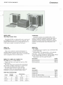
MODel CC-21. MODEL CC-12. MODEL CC-B
Card Cages 8, 12, or 21·810t Versions
These 5-100 bus card cages are ideal for OEM
Description
60-Hz operation
50-Hz operation
Model
PS8-60
P$8-50
requirements.
The card cages are of sturdy steel construction
and include a rugged retaining bar 10 insure that
cards cannot be shaken from their sockets.
The back planes include a full sel of edge
connectors which are wave-soldered in place on
Gromemco's exclusive shielded mother board.
CARD CAGE SPECIFICATIONS
Model
CC-B
GC·IZ
CC-Zl
Number
of Slots
Dimensions
H
W
8
6-5/B"
12
6-5/8"
21
6·5/8"
10-7/8"
10-718"
10-7/8"
L
,-10 1/4 "
16-3/4 "
CABLES
Description
System Zero
System One
System Two (6Z-cm long)
System Three computer (lID-em long)
Model
CBL-I
CBL·l
GBL-Z
CBL-3
f
\
'-'
MICROCOMPUTER SYSTEMS AND SOFTWARE
Cromemco
MICROCOMPUTER SYSTEMS AND SOFTWARE
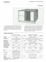
SYSTEM ZERO
40
[
o
.", '
C3
c
The System Zero (Model CS-O) is designed for
development of systems based on Cromemco's Single
Card Computer (Model seC). The CS-o has four $-100
slots. one of which is occupied by the sec.
Cromcmco's Monitor and Control Basic firmware
(MCB-216) is included.
The Monitor allows the user to read and modify
memory locations and registers and exercise input
and output ports. Break points can also be set. a
valuable feature when debugging software.
Control BASIC is an integer basic designed 10 help
get the application up Quickly. Special commands arc
provided to directly access UO ports. to directly read
and write memory locations. and 10 call machinelanguage subroutines.
Once software is developed it can be burned into
PROM memory quickly and easily using the
Cromemco 32K BYTESA VER programmer (not
included with the System Zero). Programs can then
be executed directly from the BYTESAVER. or the
PROMs can be installed in the extra sockets on the
see for resident execution.
TECHNICAL SPECIFICATIONS
Processor:
4 MHz Z-80A
Cycle Time:
250 nanoseconds
Minimum Instruction Execution Time:
1 microsecond
Instruction Set
158 instructions including the 78 instructions of
the 8OS0A processor
System Bus:
Industry standard $·100
ROM Memory:
6Kb
Firmware Provided:
RODS
Power:
Operates from 1 to/12012201240 volts: 50/60 cycle
Operating Environment:
0-55 degrees Centigrade
Dimensions:
14,2'·Wx3.45"Hx 13.4"0
Board Capacity:
Weight:
151bs.
4 boards
Mounting:
Boards Supplied:
see
RAM Memory:
IKb
Cabinet: optional rack-mount brackets available
(Model RMB-O)
MICROCOMPUTER SYSTEMS ANO SOFTWARE
Cromemco
SYSTEM ONE
41
The System One is an 8'8101 $·100 bus system
which can be used for Z-80A or 68000 system
development. The basic System One (Model CS·1)
comes with Cromemco's Z-80A processor (ZPUj,
floppy disk controller (16FDC). and 64K RAM memory
(64KZ). The unit has two 5-1/4" floppy disk drives
with 780K storage capacity.
The hard disk version of the System One (Model
CS-1H) substitutes a 21 Megabyte Winchester hard
disk drive for one of the floppy drives and includes
Cromcmco's WOI, Winchester Disk Interface.
The CS-l and CS-IH can also be configured with
Cromemco's DPU board in place of the ZPU to allow
both Z-BOA and 68000 software development.
The System One can lake advantage of all the
software listed in the software section that follows.
TECHNICAL SPECIFICATIONS
68000 and Z-80A Based Systems
Z·60A Based Systems
CS-tH
C~I
CS-1D2
CS-1D5E
CS-tHD5E
CS-tHD2
Processor
Z-80A
68000 and Z-80A
Clock Rate
4 MHz
68000: 8 MHz 1 Z-80A: 4 MHz
158 instructions including the
78instructions of the8080A processor
68000: Over 1000 instructions in 56 main types 1 Z-80A: 158 instructions
including the 78 instructions of the 8080A processor
Instruction Set
512Kb (ECC)·
256Kb
256Kb
RAM Memory
64Kb
ROM Firmware
ROOS
ROOS and Diagnostics
Serial Interface
RS-232 or current loop
RS·232 or current loop
Processor Control
512K (ECC)·
Software controlled switching between 68000 lind Z-aOA
N/A
Floppy Disk Storage
780Kb
390Kb
780Kb
780Kb
390Kb
390K
Hard Disk Storaget
None
21 Mb
Nono
None
21 Mb
21 Mb
OPU.256KZ.
16FDC
DPU. MCU.
5t2M5U.16FDC
DI'U. 256KZ.
wm. 16FDC
OI'U. MCU.
512MSU. \VOl.
16FDC
800ards
Board Capacity
Boards Supplied
ZPU.64KZ.
16FOC
Power Supply
Dimensions
Weight
Mounting
Operating Environment
ZPU. \VOl.
64KZ. 16FOC
$.>00
S·loo
Operates from 1001115113012201
2401260 volts: 50160 cycle
Operates from 10011151130122012401260 volts: 50/60 cycle
+ 8 volts @ 30A. + 18 volts
@ 15A. - 18 volts @ 15A
+ 8 volts @ 30A. + 18 volts @ 15A. - 18 volts @ 15A
0"
Power
8 boards
14.2"W)( 7.0"H)( 17.8"0
14.2"W)( 7.0"H)( 17,8"0
45 Ibs,
51 Ibs.
451bs.
461bs.
51 Ibs.
Cabinet: optional rack·mount
brackets available
Cubinet: optional rack·mount brllckets available
0-40 degrees Centigrade
0-40 degrees Centigrade
'ECC stands for error checkmg and correCl1on.
tUnformatted.
521bs.
Gromemco
MICROCOMPUTER SYSTEMS ANO SOfTWARE
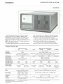
SYSTEM TWO
.2
The System Two (Model CS-2) is designed fOT rackmount use and has 215-100 card slots. Like the
System One. it uses 5 Y."· floppy disk drives and can be
Qulnued with either Cromcmco's ZPU or DPU central
processor. An optional 21 Megabyte Winchester hard
disk drive (Model HD-20J is also available.
TECHNICAL SPECIFICATIONS
Z-80A HUled Systems
cs-,"
cs-,
Proce550T
Clock Rate
Instruction Sct
RAM Memory
ROM Firmware
Serilllinlerface
Processor Control
Floppy Di,k Storage
Hard Disk Storaget
Board Capacity
80l1rd, Supplied
B.,
Power
UOA
4 MHz
156 instructions includmg 76
instructions of the 8080A processor
MKb
RODS
RS·232 or current loop
NfA
780Kb
Nooo
21 Mb
21 boards
ZPU. WOI.
ZPU.64Kz..
16FDC
64Kz.. 16FOC
C5-2HD2
CS-2D5E
C5-ZHD5E
68000 and UOA
68000: 8 Milt
Z-80A: 4 MI17;
68000, Q,-cr 1000 instructions in 56 mnin types I zao/\: 156 inslruclion~
IIlcluding 78 instructions of the 8080A processor
256Kb
512Kb(ECC)'
256Kb
512Kb (EeC)"
RODS and Dillgnoslics
RS·232 or current loop
Soltwnrc controlled switching betwC(ln 68000 and Z-80A
780Kb
None
NOlle
21 J\Ib
2\ Mb
21 boards
OPU, 256KZ.
OPU, MCU,
DPU.256KZ.
OPU. MCU.
512MSU,16t'OC
16 H>C
t6FOC, WOI
512MSU, WOI.
16FOC
S- ...
Operates from 1001115 13012201
2401260"0115: ~60 cycle
Power Supply
.. 8 '1llls @ 30/\... 18 ,'0115 @ 15/\.
- 18 "ohs @ 15/\
12·1 4"H l< 19"\\1 l< 2Q.3!4 "0
Dimensions
131,1 x 48.3 x 52,7 em)
Weight
56lbs.
62 Ihs.
Mounting
For Rae" Mounting
Operating En,'lronment
o to 40 degrees Centigrade
ECC stnnds for error chcekmg and correction.
tUnformlllled.
.
68000 and Z-80A Based Systems
C5-2D2
S- ...
Opera1es from 1001115/130122012401260 "olts; 50:60 cycle
.. 8 "0115 @ 30/\. + 18 volts @ 15/\. - 18 ,'oils @ 15/\
\2,1 4"H x 19"W x 2Q.314 "0 131.1
561bs.
l<
48.3 x 52.7 em)
571bs.
621bs.
For Rack Mounting
o to 40 degrees Centigrade
631bs.
MICROCOMPUTER SYSTEMS ANO SOFTWARE
Cromemco
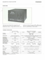
SYSTEM THREE
43
The lop-of-the-Iine System Three (Model CS-3A)
uses a-inch floppy disk drives (1.2 Megabyte capacity
each) and has 21 5-100 card slots. The hard disk
version {Model CS-3H) replaces one of the B-inch
floppy drives with a 21 Megabyte Winchester hard
disk drive.
The System Three can be used for ZrBOA software
development when equipped with the ZPU card or for
both Z-80A and 68000 software development using
the DPU card. The 21 card slots of the System Three
mean Ihal a DPU based system eGo;;' easily accommodate 4 Megabytes of memory using Cromemco's
512MSU memory storage units.
TECHNICAL SPECIFICATIONS
Z·80A Based Systems
C5-3H
C5-3A
2-aQA
Processor
Clock Rate
Instruction Set
68000 and Z·80A Based Systems
CS-3D2
CS-3D5E
CS-3HD2
CS-3HD5E
68000 and Z-80A
<I MHz
68000, 8 MHz I Z-aOA: 4 MHz
158 instructions including the
78 instructions o£lhe8080A processor
68000: Over 1000 instructions in 56 main types 1 Z-80A: 158 instruclions
including the 78 instructions of the 6080A processor
RAM Memory
MKb
ROM Firmware
RODS
RODS and Diagnostics
Serial Interface
RS·232 or current loop
RS·232 or current loop
Processor Control
256Kb
512Kb (ECC)'
256Kb
5l2Kb(ECC)'
Software controlled swilching belween 68000 and Z-80A
N/A
Floppy Disk Storage
2.'1 Mb
1.2 Mb
2.4 Mb
2.4 Mb
1.2 Mb
1.2 Mb
Hard Disk Storaget
None
21 Mb
None
None
21 Mb
21 Mb
DPU. 256KZ.
WDl.64FOC
DPU. MCU.
512MSU, WDI.
64FDC
21 boards
Board Capacity
Boards Supplied
ZPU.64KZ.
64FDC
21 boards
ZPU. \vOL
64KZ, 64FDC
OPU. 256KZ.
64FDC
OPU. MCU.
512MSU.64FDC
5·100
~100
Operates from 100111511301
22012401260 volts: 50/60 cycle
Operales from 1001115/\30122012401260 volts: 50160 cycle
Power Supply
+ 8 volts @ 30A, + 18 volts
@ 15A. - 18 volts@ 15A
+8 volts@30A. + 18 volts@ 15A. -18 volls@ 15A
Dimensions
12-114"H x 19"W x 20-314"0
(ll.1 x 48.3)( 52.7 em)
12-1/4"H x 19"W x 20·3/4"0
{31.1 x 48.3 x 52.7 em)
Weight
84 Ibs.
Boo
Power
Mounting
.
Operating Environment
901bs.
841bs.
85 Ibs.
901bs.
For Rack Mounting
For Rack Mounting
0-40 degreos Centigrade
0-40 degrees Centigrade
ECC stands for error chedang and corrocllon.
tUnformatled.
91 lbs.
MICROCOMPUTER SYSTEMS ANO SOFTWARE
Cromemco
C·l0 Personal Computer
44
The Cromemco C-lO personal computer product
line meets the most exacting professional needs at a
very affordable price.
The basic C-I0 includes the Z-80A microprocessor,
64K bytes of RAM. 24K byles of ROM. and a high
resolution 12" green phosphor CRT capable of
displaying 80 columns and 25 lines of texl or 160
columns and 72 lines of business graphics
characters.
The C-lOSP Super Pak provides the same high
quality Cromemco C·lO computer plus a keyboard
and a Slit" disk drive with 390K capacity. A variety
of software packages are also included with the
Super Pak such as a word processor. a financial
spread sheet. Structured BASIC, an investment
analysis program, the CDOS operating system
ICromemco's enhanced version of CP/M), and
complete operating instructions.
The keyboard. screen, and system layout are the
result of an extensive human factors engineering
TECHNICAL SPECIFICATIONS
Processor: High speed Zr80A microprocessor operating
at 4 MHz clock frequency
Internal Memory: 64K bytes of internal Random
Access Memory. 24K bytes of internal Read Only
Memory
Operating System: Cromemco's enhanced CPIM
operating system
Display: High resolution 12" CRT for professional
quality displays and graphics
Graphics modes:
Pixel: 160 x 72
Line; High resolution (720 x 384)
Character: Special graphic characters
P-31 green phosphor, standard
25 lines of 80 characters each
Four character sets included:
ASCII. Boldface, Graphics. ScientiHclTechnical
program that provide maximum comfort and efficiency,
The CtO uses Cromemco's enhanced version of
CPIM which allows the user access to the extensive
library of current CPIM programs and to the wide
variety of advanced programming languages avail·
able from Cromemco. This gives the user access to
higher level languages such as FORTRAN, COBOL.
RATFOR, and LISP. Furthermore, software programs
that are developed for use with the C-lO can be used
on larger Cromemco systems-even the high performance. 68000-based, multi-user computers.
The ClO can emulate a wide variety of terminals
and data protocols. Several units can be
interconnected and used as distributed work stations.
interfaced to larger Cromemco systems. or used as
front end processors for mainframe computers.
A number of options are available for the ColO
including a second 5 1/4 .. floppy disk drive, a lelterquality 120-words-per-minute Daisy wheel printer,
and a swivel-and-tilt ergonomic stand.
Data Communications: RS232 serial data communications
porI. Parallel 110 expansion and printer port,
Serial printer port. Can emulate a wide variety of
terminals and protocols.
Peripherals: Sill" floppy disk available with 390K bytes
storage capacity per diskelle. Up to two drives
per system. Daisy wheelletter-quality printer.
Software:
Operating system
Write Master Word Processing
Plan Master Spread Sheet Calculator
Money Master Investment Analysis
Structured BASIC
Also available: RATFOR. COBOL, FORTRAN,
LISP. Macro Assembler, Spelling Correction
Program, Variety of CPIM programs.
MICROCOMPUTER SYSTEMS ANO SOFTWARE
Cromemco
SOFTWARE
The disk-based software for the System One,
System Two. and System Three systems is among the
best and most extensive in the industry. When
ordering software for 8 System One or System Two.
add a "oS" suffix to the software model number to
indicate software on a 5" diskette. For the System
Three. add a ·'·L'· surrix to indicate an 8" diskette.
OPERATING SYSTEMS
There is a choice of two operating systems for
ZPU-based systems. COOS is an enhancement of the
industry-standard CP/M operating system and is
designed for single-user. single-task applications.
CROMIX is a UNIX-like system designed for singleuser. multi-tasking or multi-user. multi-tasking
applications.
For DPU·based systems. a special version of
CROMIX. called CROMIX-D. is available. CROMIX-D
is a single- or multi-user. multi-tasking system. where
different users or tasks can run under either the
Z-80A or 68000 processor of the DPU. CROMIX-D
must be installed on a DPU based system in order for
that system to be able 10 take advantage of the
68000-based software languages listed below.
OPERATING SYSTEMS AND DIAGNOSTICS
Description
CROMIX Multi-user. Multi-tasking
(68000·based systems)
CROMIX Multi-user. Multi-tasking
(Z-80A Based Systems)
Z-80A COOS Single-user
Cromemco Diagnostics Software
Model
CRO-DSIL
CROMIX-SIL
DOS-SIL
CDS-SIL
68000 LANGUAGES
Description
68000 Macro Assembler
68000 C Compiler
68000 COBOL Compiler
68000 FORTRAN 77
68000 Pascal Compiler
68000 BASIC
Model
ASM-D-SIL
CCC-D-S/L
COB-D-SIL
FOR-D-SIL
PAS-D-S/L
STB-D-SIL
l·80 LANGUAGES
Description
Model
CCC-SIL
FDA-SIL
FDB-S/L
C Compiler
Z-80 Macro Assembler
16K Extended BASIC Incremental
Compiler
COBOL Compiler
FORTRAN IIV Compiler
RATFOR
LISP Interpreter
RPG-II Compiler
Structured BASIC
FIlC-SIL
FDF-S1L
FDR-SIL
LSP-S/L
RPG-SIL
STB-S/L
SOFTWARE TOOLS (For Z·BoA Based Systems)
Description
Cromemco Overlay Linker
Data Base Management System
Dazzler Graphics Software
lOP Development Software
Keyed Sequential Access Method
Remote Batch Terminal Emulator
SOl Graphics Software
Trl·SOl Software
Word Processing Software
Model
COLL-SIL
DBM-SIL
DGR-S1L
IDS-S/L
KSAM-SIL
RBTE-S1L
SGS-SIL
TSDI-SIL
WPS-SIL
MASTER SERIES IEnd·User Tools)
Description
WriteMoster, Word Processing
SpellMaster, Spelling Correction
Program
PlanMaster, Spreadsheet Analysis
SJideMaster. Custom Graphics
FontMaster. standard fonts for
adding text or generate custom fonts
Model
WRMR-SIL
SPMR-S/L
PLMR-S/L
SLMR-SIL
FOMR-S/L
45
GENERAL INFORMATION
,
,
J
Cromemco
DEDICATED TO QUALITY
Cromemco. Incorporated. the world's largest and
most successful 5-100 based microcomputer manufaclurer. is known for high-quality. high-reliability
products.
Cromemco has. from the beginning. set a goal of
building "tomorrow's computers today:' We place
tremendous imporlance on continuing R&D on system
products. software. manufacturing and testing techniques. and support for our many customers.
Cromemco products have achieved a world-wide
reputation for high quality at a reasonable price.
The company operates its office. laboratory, and
manufacturing facilities in a modern complex in
Mountain View, California. Every step in the manufacturing process is controlled in-house and
considerable attention is paid to quality control and
reliability engineering.
Every product. whether iI's a single board or the
most complex computer. is thoroughly tested and
burned-in before leaving the factory.
More than 35.000 Cromemco computers are now at
work around the world. Acceptance has been worldwide thanks largely to a strong network of
experienced dealers and distributors.
Cromemco has been recognized by leading industry
experts as one of the fastest growing corporations in
the country and now ranks among the top 100 firms
in the data processing industry. The advanced. high
quality software available to our customers is one
reason why Cromemco systems are often used in
applications where maximum reliability is essential:
business and finance. engineering and control.
medicine. scientific research and TV weather
reporting.
And since we have always used extensive
engineering to make our systems rugged. many of our
customers choose Cromemco systems for applications
in tough environments: industrial process control.
offshore oil rigs. robotics. ship-board and in-flight
systems.
Manufacturing: Quality builds reliability
Since 1975. when our first SolDO boards were
introduced. we have recognized the value of close
quality control over every step in manufacturing.
The value to our customer is consistent. reliable.
repeatable performance-board to board. system to
system.
The value 10 Cromemco has been in seeing our
boards and systems accepted throughout the
computer world as Quality standards. as documented
in a recent study done by Bunker Ramo for the U.S.
Air force.
GENERAL INFORMATION
The fact that our products are being widely used
by the most demanding systems integrators of
engineering and office systems is quiet testimony to
the excellence of our manufacturing process and
quality control.
It starts at incoming ac
All components arc hot-rail tested against the
manufacturer's toughest specs. then put through DC
parametric tests for all device functions.
Bare boards are checked for shorts and opens and
baked ror 24 hours prior to assembly.
Complex LSI devices arc pretested on speciallydesigned test systems.
We maintain constant vigilance over quality
throughout the assembly process. We perrorm a
variety or visual and computer-controlled electrical
inspections on every assembled board to make sure
every device is runctioning properly. Every part or
every system is essential to the reliable operation of
your equipment.
By the time our S·lDO boards or systems are
packed for shipment. each has already run
successfully in our own test area. has passed a
complex series of performance tests and has gone
through burn-in. Quality controls. uniformly and
consistently applied. are the only way to assure longterm reliability.
Service closes the loop
Finally. to close the quality loop. we give our
customers the best possible documentation. training.
and field support because we know that long-term
profitable growth will come only from completely
satisfied end users. We have worked hard to build
and keep a reputation for concerned. capable.
professional service after the sale. Third party
service is available nationwide to Cromemco
customers from TRW Customer Service Division.
INTERNATIONAL ASSOCIATION OF
CROMEMCO USERS
News on products and applications is available to
the world-wide base of Cromemco users through the
International Association of Cromemco Users (IACU).
an independent users group formed in 1980. The
purpose of the (ACU is to act as an independent twoway communications center for Cromemco users.
Through their publication. 110 NEWS. the Association
serves as a clearinghouse for information about
Cromemco products. applications. available software
and services. and dealers.
49
PART NUMBER INDEX
Part
Page
Part
Pago
Part
Page
4PIO
26
CS·1D5E
41
FOR·D·S/L
45
BPIO
27
CS·IHD2
41
29
16KZ
10
CS·IHD5E
41
GPID
IDS-SIL
45
32KBS
14
CS-2
42
lOP
16
4BKTP
34
CS·2H
42
KSAM·S/L
45
64FDe
25
CS·2D2
42
LSp·SIL
45
64KZ
11
CS-2D5E
42
MeR·ZIG
256KZ
12
CS·2HD2
42
MCU
13
512MSU
13
CS·2HD5E
42
PAS·n·SIL
45
ADel2
23
CS·3A
43
PLMR·SfL
45
ASM·D·S/L
45
CS-3H
43
PRI
30
CDL-1
38
CS·3D2
43
P5·8
38
CBL-2
38
CS·3D5E
43
QORT
27
CDL-3
38
CS·3HD2
43
ROTE-S/L
45
eC·8
38
CS-3HD5E
43
RGB
13
CC·12
38
CSP
20
RPG-SIL
45
CC-21
38
CTI
31
SCC
8
CCC·O·SIL
45
D+7A
21
SOl
34
eee-SIL
45
DAC12
22
SGS·SIL
45
COS-SIL
45
DHM·SIL
44
SLMR·SfL
45
CNI
18
OGR·SIL
45
SPMR·Slt
45
COB·D·SIL
45
DOS-SIL
45
STO·D·SfL
45
COLL-S/L
45
OPU
6
5TH·SIL
45
45
8
CRO·OSIL
45
EXC
38
TSDI-S/L
CROMIX·S/L
45
FDA·SIL
45
WOI
C·lO
44
FDB·SIL
45
WPS-S/L
45
CS-O
40
FDG-S/L
45
WRMR·SIL
45
es·!
41
FDF·SfL
45
WWB
38
eS·1H
41
FOR·SIL
45
ZPU
CS·tD2
41
FOMR·S/L
45
2
7
SALES SUPPORT OFFICES
For additional information on Cromemco products
and services, contact one of the sales support offices
listed below.
World Headquarters
Cromemco, Inc. .
280 Bernardo Avenue
P.O. Box 7400
MI. View. CA 94039
(415) 964-7400
Domestic Sales Support Offices
Cromemco. Inc.
Executive Place III
50 Mall Road. Suite 201
Burlington. MA 01803
(617) 229-2680
Cromemco, Inc.
1150 Hammond Drive. Suite 04245
Atlanta. GA 30328
(404) 391-9433
Cromemco. Inc.
1900 E. Golf Road. Suite 100
Schaumburg. IL 60195
(312l49Q.0850
International Sales Support Offices
Cromemco, A/S
Vesterbrogade Ie
1620 Copenhagen V
Denmark
(45-01) 157272
Cromemco/Germany
6236 Eschborn 1
Frankfurter Sir. 33-35
P.O. Box 5267
Frankfurt Main. Germany
(00·49) 481606
l
Cromemco'
Cromemco, Inc
280 Be/Bardo Ave
PO Box 1400
-
Mountam View, CA 94039
(415) 964·1400
TWX 910-379 6988
Q
a
COlIYIIghl Cromemc:o 1f>C: 1933
03&3801.1
"',"teo ,n II S A
0238303