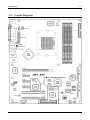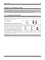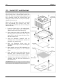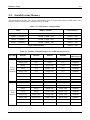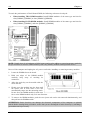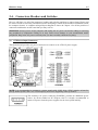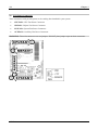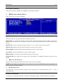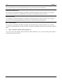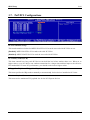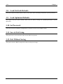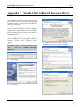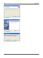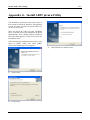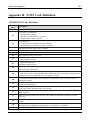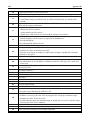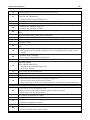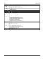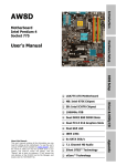
1
AX8 Series (AX8-3rd Eye/AX8/AX8-V) AMD Athlon 64 (FX) System Board Socket 939 User’s Manual 4200-0431-01 Rev. 1.00 Copyright and Warranty Notice The information in this document is subject to change without notice and does not represent a commitment on part of the vendor, who assumes no liability or responsibility for any errors that may appear in this manual. No warranty or representation, either expressed or implied, is made with respect to the quality, accuracy or fitness for any particular part of this document. In no event shall the manufacturer be liable for direct, indirect, special, incidental or consequential damages arising from any defect or error in this manual or product. Product names appearing in this manual are for identification purpose only and trademarks and product names or brand names appearing in this document are the property of their respective owners. This document contains materials protected under International Copyright Laws. All rights reserved. No part of this manual may be reproduced, transmitted or transcribed without the expressed written permission of the manufacturer and authors of this manual. If you do not properly set the motherboard settings, causing the motherboard to malfunction or fail, we cannot guarantee any responsibility. AX8 Series Table of Contents Chapter 1. 1-1. 1-2. Chapter 2. 2-1. 2-2. 2-3. 2-4. Hardware Setup.................................................................... 2-1 Install The Motherboard...........................................................................2-1 Install CPU and Heatsink.........................................................................2-2 Install System Memory ............................................................................2-3 Connectors, Headers and Switches ..........................................................2-5 (1). ATX Power Input Connectors........................................................2-5 (2). FAN Power Connectors .................................................................2-6 (3). CMOS Memory Clearing Header ..................................................2-7 (4). Wake-up Header.............................................................................2-8 (5). Front Panel Switches & Indicators Headers ..................................2-9 (6). Additional USB Port Headers......................................................2-10 (7). Additional IEEE1394 Port Headers (AX8-3rd Eye/AX8)..............2-11 (8). Front Panel Audio Connection Header ........................................2-12 (9). Internal Audio Connectors ...........................................................2-13 (10). GURU Clock Connection Header................................................2-13 (11). PCI Express x16 Slot ...................................................................2-14 (12). PCI Express x1 Slots....................................................................2-14 (13). Floppy and IDE Disk Drive Connectors ......................................2-15 (14). POST Code Display .....................................................................2-16 (15). Serial ATA Connectors .................................................................2-17 (16). Status Indicators...........................................................................2-17 (17). Back Panel Connectors ................................................................2-18 Chapter 3. 3-1. 3-2. 3-3. 3-4. 3-5. 3-6. 3-7. 3-8. Introduction .......................................................................... 1-1 Features & Specifications ........................................................................1-1 Layout Diagram .......................................................................................1-3 BIOS Setup............................................................................ 3-1 µGuru Utility............................................................................................3-2 Standard CMOS Features.........................................................................3-9 Advanced BIOS Features.......................................................................3-12 Advanced Chipset Features....................................................................3-14 Integrated Peripherals ............................................................................3-16 Power Management Setup .....................................................................3-20 PnP/PCI Configurations.........................................................................3-23 Load Fail-Safe Defaults .........................................................................3-24 User’s Manual 3-9. 3-10. 3-11. 3-12. Load Optimized Defaults .......................................................................3-24 Set Password ..........................................................................................3-24 Save & Exit Setup ..................................................................................3-24 Exit Without Saving...............................................................................3-24 Appendix A. Install VIA 4-in-1 Driver ................................................................. A-1 Appendix B. Install Audio Driver ......................................................................... B-1 Appendix C. Install LAN Driver ........................................................................... C-1 Appendix D. Install VIA USB 2.0 Driver .............................................................D-1 Appendix E. Install VIA South Bridge SATA RAID Driver ............................... E-1 Appendix F. Install AMD Athlon 64 Processor Driver ....................................... F-1 Appendix G. Install ABIT µGuru Utility ..............................................................G-1 Appendix H. POST Code Definition .....................................................................H-1 Appendix I. Troubleshooting (Need Assistance?)................................................ I-1 Appendix J. How to Get Technical Support .........................................................J-1 AX8 Series Introduction 1-1 Chapter 1. Introduction 1-1. Features & Specifications 1. CPU • Supports AMD Socket 939 Athlon 64/64FX Processor with 2GHz system bus using Hyper Transport™ Technology • Supports AMD K8 CPU Cool ‘n’ Quiet Technology 2. Chipset • VIA K8T890 + VT8237 3. CPU Integrated Dual Channel Memory Controller • Four 184-pin DIMM slots (Un-buffered, Non-ECC DIMM) • Supports 2 DIMM Single Channel DDR 400/333/266 (Max. 2GB) • Supports 4 DIMM Dual Channel DDR 400/333/266 (Max. 4GB) 4. PCI Express X16 Graphics • PCI Express X16 graphics delivers up to 8GB/s bandwidth 5. SATA RAID • Supports SATA RAID 0/1 (Connectors SATA1~SATA2) 6. Second SATA RAID (AX8-3rd Eye/AX8) • • • • Supports SATA RAID 0/1 (Connectors SATA3~SATA4) Supports SATA RAID 0/1/0+1 (Connectors SATA1~SATA4) Supports RAID 0/1/JBOD (Connector IDE3) Supports RAID JBOD (Connectors SATA1~SATA4 and IDE3) 7. Gigabit LAN • Onboard Gigabit PCI Ethernet Controller 8. IEEE 1394 • Supports IEEE 1394 at 100/200/400 Mb/s transfer rate (AX8-3rd Eye/AX8) 9. Audio • • Onboard 5.1-channel Audio CODEC Optical S/PDIF Input/Output (AX8-3rd Eye/AX8) 10. ABIT Engineered • ABIT µGuru™ Technology • ABIT GuruClock™ Technology (AX8-3rd Eye) • ABIT CPU ThermalGuard™ Technology User’s Manual 1-2 Chapter 1 11. Internal I/O Connectors • • 1x PCI Express x16 slot 3x PCI Express x1 slots • 2x PCI slots • 1x Floppy port supports up to 2.88MB • 2x Ultra DMA 33/66/100/133 connectors (AX8-V) • • 3x Ultra DMA 33/66/100/133 connectors (AX8-3rd Eye/AX8) 4x SATA 150 Connectors (AX8-3rd Eye/AX8) • 2x SATA 150 Connectors (AX8-V) • 2x USB 2.0 headers • 1x IEEE 1394 header (AX8-3rd Eye/AX8) • 1x FP-Audio header • 1x CD-IN header 12. Back Panel I/O • 1x PS/2 keyboard, 1x PS/2 mouse • 1x Serial port connector, 1x Parallel port connector • 1x S/PDIF In connector (AX8-3rd Eye/AX8) • 1x S/PDIF Out connector (AX8-3rd Eye/AX8) • 1x AUDIO1 connector (Rear-Left / Rear-Right, Center/Subwoofer) • 1x AUDIO2 connector (Mic-In, Line-In, Front-Left/Front-Right) • 4x USB 2.0 Connectors • 1x IEEE 1394 Connector (AX8-3rd Eye/AX8) • 1x RJ-45 LAN Connector 13. Miscellaneous • ATX form factor: 305 x 245 mm 14. Order Information Model Features AX8-3rd Eye 4x SATA RAID 0/1/0+1 ports, 3x PATA ports, IEEE1394, S/PDIF, GuruClock AX8 4x SATA RAID 0/1/0+1 ports, 3x PATA ports, IEEE1394, S/PDIF AX8-V 2x SATA RAID 0/1 ports, 2x PATA ports Specifications and information contained herein are subject to change without notice. AX8 Series Introduction 1-3 1-2. Layout Diagram User’s Manual 1-4 AX8 Series Chapter 1 Hardware Setup 2-1 Chapter 2. Hardware Setup Before the Installation: Turn off the power supply switch (fully turn off the +5V standby power), or disconnect the power cord before installing or unplugging any connectors or add-on cards. Failing to do so may cause the motherboard components or add-on cards to malfunction or damaged. 2-1. Install The Motherboard Most computer chassis have a base with many mounting holes to allow motherboard to be securely attached on and at the same time, prevented from short circuits. There are two ways to attach the motherboard to the chassis base: 1. use with studs 2. or use with spacers In principle, the best way to attach the board is to use with studs. Only if you are unable to do this should you attach the board with spacers. Line up the holes on the board with the mounting holes on the chassis. If the holes line up and there are screw holes, you can attach the board with studs. If the holes line up and there are only slots, you can only attach with spacers. Take the tip of the spacers and insert them into the slots. After doing this to all the slots, you can slide the board into position aligned with slots. After the board has been positioned, check to make sure everything is OK before putting the chassis back on. ATTENTION: To prevent shorting the PCB circuit, please REMOVE the metal studs or spacers if they are already fastened on the chassis base and are without mounting-holes on the motherboard to align with. User’s Manual 2-2 Chapter 2 2-2. Install CPU and Heatsink This motherboard provides a ZIF (Zero Insertion Force) Socket 939 to install AMD Socket 939 CPU. The CPU you bought should contain with a kit of heatsink, cooling fan, retention frame and blackplate. If that’s not the case, buy one specially designed for Socket 939. Please refer to the figure shown here to install CPU and heatsink. (For reference only. Your Heatsink & Fan Assembly may not be exactly the same as this one.) 1. Locate the Socket 939 on this motherboard. Pull the CPU release lever sideways to unlatch and then raise it all the way up. 2. Drop the processor with its pin side down into the CPU socket. Do not use extra force to insert CPU; it only fits in one direction. Close the CPU release lever. 3. Align the Backplate Standoffs with the mounting holes on motherboard. Position the backplate onto motherboard. 4. Place the Retention Frame onto the motherboard and align it with the Backplate Standoffs. 5. Place heatsink on top of CPU, and make sure the heatsink fits properly on the retention frame. 6. Hook both sides of the Spring Clip onto the Mounting Tabs of Retention Frame. Tighten screws until the Spring Clip is fully installed. 7. Attach the fan connector of Heatsink & Fan Assembly with the CPU-FAN connector on the motherboard. ATTENTION: Do not forget to set the correct bus frequency and multiple for your processor. AX8 Series Hardware Setup 2-3 2-3. Install System Memory This motherboard provides four 184-pin DDR DIMM slots for Single/Dual Channel DDR 400/333/266 memory modules with memory expansion size up to 4GB. Table 2-1. Valid Memory Configurations Bank Memory Module Total Memory Bank 0, 1 (DIMM1) 256MB, 512MB, 1GB 256MB ~ 1GB Bank 2, 3 (DIMM2) 256MB, 512MB, 1GB 256MB ~ 1GB Bank 4, 5 (DIMM3) 256MB, 512MB, 1GB 256MB ~ 1GB Bank 6, 7 (DIMM4) 256MB, 512MB, 1GB 256MB ~ 1GB 256MB ~ 4GB Total System Memory Table 2-2. Unbuffered DIMM Support For AMD 939-pin Processor Data Bus 64-bits (Single Channel) 128-bits (Dual Channel) DIMM1 DIMM2 DIMM3 DIMM4 Maximum DRAM Speed Single rank N/A Empty N/A DDR400 Double rank N/A Empty N/A DDR400 Empty N/A Single rank N/A DDR400 Empty N/A Double rank N/A DDR400 Single rank N/A Single rank N/A DDR400 Single rank N/A Double rank N/A DDR400 Double rank N/A Single rank N/A DDR400 Double rank N/A Double rank N/A DDR333 Single rank Single rank Empty Empty DDR400 Double rank Double rank Empty Empty DDR400 Empty Empty Single rank Single rank DDR400 Empty Empty Double rank Double rank DDR400 Single rank Single rank Single rank Single rank DDR400 Single rank Single rank Double rank Double rank DDR400 Double rank Double rank Single rank Single rank DDR400 Double rank Double rank Double rank Double rank DDR333 User’s Manual 2-4 Chapter 2 To reach the performance of Dual Channel DDR, the following rules must be obeyed: • When installing TWO DIMM modules: Install DIMM modules of the same type and size for slots [DIMM1]+[DIMM2] or slots [DIMM3]+[DIMM4]. • When installing FOUR DIMM modules: Install DIMM modules of the same type and size for slots [DIMM1]+[DIMM2], and slots [DIMM3]+[DIMM4]. NOTE: Usually there is no hardware or BIOS setup requires after adding or removing memory modules, but you will have to clear the CMOS memory first if any memory module related problem occurs. Power off the computer and unplug the AC power cord before installing or removing memory modules. 1. Locate the DIMM slot on the board. 2. Hold two edges of the DIMM module carefully, keep away of touching its connectors. 3. Align the notch key on the module with the rib on the slot. 4. Firmly press the module into the slots until the ejector tabs at both sides of the slot automatically snaps into the mounting notch. Do not force the DIMM module in with extra force as the DIMM module only fit in one direction. 5. To remove the DIMM modules, push the two ejector tabs on the slot outward simultaneously, and then pull out the DIMM module. ATTENTION: Static electricity can damage the electronic components of the computer or optional boards. Before starting these procedures, ensure that you are discharged of static electricity by touching a grounded metal object briefly. AX8 Series Hardware Setup 2-5 2-4. Connectors, Headers and Switches Here we will show you all of the connectors, headers and switches, and how to connect them. Please read the entire section for necessary information before attempting to finish all the hardware installation inside the computer chassis. A complete enlarged layout diagram is shown in Chapter 1 for all the position of connectors and headers on the board that you may refer to. WARNING: Always power off the computer and unplug the AC power cord before adding or removing any peripheral or component. Failing to so may cause severe damage to your motherboard and/or peripherals. Plug in the AC power cord only after you have carefully checked everything. (1). ATX Power Input Connectors This motherboard provides two power connectors to connect to an ATX12V power supply. NOTE: It is recommended to connect to a power supply with 350W, 20A +5VDC capacity at least for heavily loaded system, and a 2A +5VSB capacity at least for supporting wake-up features. The auxiliary 12V power connector [POWER1] provides an additional power source for devices added on PCI Express slots. It is highly recommended to attach 12V power from the power supplier for the best system stability. User’s Manual 2-6 Chapter 2 (2). FAN Power Connectors These connectors each provide power to the cooling fans installed in your system. • CPUFAN1: CPU Fan Power Connector • NBFAN1: Chipset Fan Power Connector • SYSFAN1: System Fan Power Connector • AUXFAN1: Auxiliary Fan Power Connector WARNING: These fan connectors are not jumpers. DO NOT place jumper caps on these connectors. AX8 Series Hardware Setup 2-7 (3). CMOS Memory Clearing Header This header uses a jumper cap to clear the CMOS memory. • Pin 1-2 shorted (default): Normal operation. • Pin 2-3 shorted: Clear CMOS memory. WARNING: Turn the power off first (including the +5V standby power) before clearing the CMOS memory. Failing to do so may cause your system to work abnormally or malfunction. User’s Manual 2-8 Chapter 2 (4). Wake-up Header These headers use a jumper cap to enable/disable the wake-up function. • PS2-PWR1: Pin 2-3 shorted (default): Enable wake-up function support at Keyboard/Mouse port. Pin 1-2 shorted: Disable wake-up function support at Keyboard/Mouse port. • USB-PWR1: Pin 2-3 shorted (default): Enable wake-up function support at USB1 port. Pin 1-2 shorted: Disable wake-up function support at USB1 port. • USB-PWR2: Pin 2-3 shorted (default): Enable wake-up function support at USB2 port. Pin 1-2 shorted: Disable wake-up function support at USB2 port. AX8 Series Hardware Setup 2-9 (5). Front Panel Switches & Indicators Headers This header is used for connecting switches and LED indicators on the chassis front panel. Watch the power LED pin position and orientation. The mark “+” align to the pin in the figure below stands for positive polarity for the LED connection. Please pay attention to connect these headers. A wrong orientation will only cause the LED not lighting, but a wrong connection of the switches could cause system malfunction. • HLED (Pin 1, 3): Connects to the HDD LED cable of chassis front panel. • RST (Pin 5, 7): Connects to the Reset Switch cable of chassis front panel. • SPKR (Pin 13, 15, 17, 19): Connects to the System Speaker cable of chassis. • SLED (Pin 2, 4): Connects to the Suspend LED cable (if there is one) of chassis front panel. • PWR (Pin 6, 8): Connects to the Power Switch cable of chassis front panel. • PLED (Pin 16, 18, 20): Connects to the Power LED cable of chassis front panel. User’s Manual 2-10 Chapter 2 (6). Additional USB Port Headers These headers each provide 2 additional USB 2.0 ports connection through an USB cable designed for USB 2.0 specifications. AX8 Series Pin Pin Assignment Pin Pin Assignment 1 VCC 2 VCC 3 - Data 0 4 - Data 1 5 + Data 0 6 + Data 1 7 Ground 8 Ground 10 NC Hardware Setup 2-11 (7). Additional IEEE1394 Port Headers (AX8-3rd Eye/AX8) This header provides one additional IEEE1394 port connection through an extension cable and bracket. Pin Pin Assignment Pin Pin Assignment 1 TPA0 + 2 TPA0 - 3 GND 4 GND 5 TPB0 + 6 TPB0 - 7 +12V 8 +12V 9 NC 10 GND User’s Manual 2-12 Chapter 2 (8). Front Panel Audio Connection Header This header provides the connection to audio connector at front panel. • To use the audio connector at front panel, remove all the jumpers on this header, and then connect to front panel by the extension cable provided with the chassis. • To use the audio connector at rear panel, disconnect the extension cable, attach the jumpers back at pin 5-6, and pin 9-10 (default setting). Pin 1 3 5 7 9 AX8 Series Pin Assignment Audio Mic. Audio Mic. Bias Speaker Out Right Channel X Speaker Out Left Channel Pin 2 4 6 8 10 Pin Assignment Ground VCC Speaker Out Right Channel Return NC Speaker Out Left Channel Return Hardware Setup 2-13 (9). Internal Audio Connectors These connectors connect to the audio output of internal CD-ROM drive or add-on card. (10). GURU Clock Connection Header This header is reserved for connecting ABIT’s exclusive GURU Clock. User’s Manual 2-14 (11). PCI Express x16 Slot This slot is used to attach the next generation of graphics architecture. (12). PCI Express x1 Slots These slots are used to attach the next generation of I/O architecture. AX8 Series Chapter 2 Hardware Setup 2-15 (13). Floppy and IDE Disk Drive Connectors The FDC1 connector connects up to two floppy drives with a 34-wire, 2-connector floppy cable. Connect the single end at the longer length of ribbon cable to the FDC1 on the board, the two connectors on the other end to the floppy disk drives connector. Generally you need only one floppy disk drive in your system. NOTE: The red line on the ribbon cable must be aligned with pin-1 on both the FDC1 port and the floppy connector. Each of the IDE port connects up to two IDE drives at Ultra ATA/100 mode by one 40-pin, 80-conductor, and 3-connector Ultra ATA/66 ribbon cables. Connect the single end (blue connector) at the longer length of ribbon cable to the IDE port of this board, the other two ends (gray and black connector) at the shorter length of the ribbon cable to the connectors of your hard drives. NOTE: Make sure to configure the “Master” and “Slave” relation before connecting two drives by one single ribbon cable. The red line on the ribbon cable must be aligned with pin-1 on both the IDE port and the hard-drive connector. For models “AX8-3rd Eye” and “AX8”, a third IDE port is supported via [IDE3] connector, making “RAID 0”, “RAID 1”, “RAID 0+1”, and “JBOD” services possible via the combination of connectors [SATA3], [SATA4], and [IDE3] besides their regular SATA and PATA connection. User’s Manual 2-16 Chapter 2 (14). POST Code Display This is an LED device to display the “POST” Code, the acronym of Power On Self Test. The computer will execute the POST action whenever you power on the computer. The POST process is controlled by the BIOS. It is used to detect the status of the computer’s main components and peripherals. Each POST Code corresponds to different checkpoints that are also defined by the BIOS in advance. For example, “memory presence test” is an important checkpoint and its POST Code is “C1”. When the BIOS execute any POST item, it will write the corresponding POST Code into the address 80h. If the POST passes, the BIOS will process the next POST item and write the next POST Code into the address 80h. If the POST fails, we can check the POST Code in address 80h to find out where the problem lies. This LED device also displays the “POST” Code of AC2003, an “uGuru” chipset developed exclusively by ABIT computer. NOTE: The decimal point lights up when executing the AC2003 POST action. See Appendix for both AWARD and AC2003 POST Code definition. AX8 Series Hardware Setup 2-17 (15). Serial ATA Connectors These connectors are provided to attach one Serial ATA device at each channel via Serial ATA cable. NOTE: The connectors [SATA1] and [SATA2] provide “RAID 0” or “RAID 1” service besides their regular SATA connection. For models “AX8-3rd Eye” and “AX8”, additional “RAID 0+1” and “JBOD” services are provided further. (16). Status Indicators • LED1 (5VSB): This LED lights up when the power supply is connected with power source. • LED2 (VCC): This LED lights up when the system power is on. User’s Manual 2-18 Chapter 2 (17). Back Panel Connectors • Mouse: Connects to PS/2 mouse. • Keyboard: Connects to PS/2 keyboard. • LPT1: Connects to printer or other devices that support this communication protocol. • COM1: Connects to external modem, mouse or other devices that support this communication protocol. • OPT-IN1: This connector provides an S/PDIF in connection through optical fiber to digital multimedia devices. (AX8-3rd Eye/AX8) • OPT-OUT1: This connector provides an S/PDIF out connection through optical fiber to digital multimedia devices. (AX8-3rd Eye/AX8) • AUDIO1: R.L./R.R. (Rear Left / Rear Right): Connects to the rear left and rear right channel in the 5.1 channel audio system. Cen./Sub. (Center / Subwoofer): Connects to the center and subwoofer channel in the 5.1 channel audio system. • AUDIO2: Mic In: Connects to the plug from external microphone. Line In: Connects to the line out from external audio sources. F.L./F.R. (Front Left / Front Right): Connects to the front left and front right channel in the 5.1-channel or regular 2-channel audio system. • IEEE1394: Connects to devices of IEEE1394 protocol. (AX8-3rd Eye/AX8) • LAN: Connects to Local Area Network. • USB1/USB2: Connects to USB devices such as scanner, digital speakers, monitor, mouse, keyboard, hub, digital camera, joystick etc. AX8 Series BIOS Setup 3-1 Chapter 3. BIOS Setup This motherboard provides a programmable EEPROM that you can update the BIOS utility. The BIOS (Basic Input/Output System) is a program that deals with the basic level of communication between processor and peripherals. Use the BIOS Setup program only when installing motherboard, reconfiguring system, or prompted to “Run Setup”. This chapter explains the Setup Utility of BIOS utility. After powering up the system, the BIOS message appears on the screen, the memory count begins, and then the following message appears on the screen: PRESS DEL TO ENTER SETUP If this message disappears before you respond, restart the system by pressing <Ctrl> + <Alt> + <Del> keys, or by pressing the Reset button on computer chassis. Only when it failed by these two methods can you restart the system by powering it off and then back on. After pressing <Del> key, the main menu screen appears. NOTE: In order to increase system stability and performance, our engineering staffs are constantly improving the BIOS menu. The BIOS setup screens and descriptions illustrated in this manual are for your reference only, may not completely match what you see on your screen. In the BIOS Setup main menu, you can see several options. We will explain these options step by step in the following pages of this chapter, but let us first see a short description of the function keys you may use here. User’s Manual 3-2 Chapter 3 3-1. µGuru Utility Brand Name: This item displays the CPU model name, for example: AMD Athlon™ 64 processor 4000+. Frequency: This item displays the processor speed. CPU Operating Speed: This item displays the CPU operating speed according to the type and speed of your CPU. You can also select the [User Define] option to enter the manual option. User Define: WARNING: The wrong settings of the multiplier and external clock in certain circumstances may cause CPU damage. Setting the working frequency higher than the PCI chipset or processor specs, may cause abnormal memory module functioning, system hangs, hard disk drive data lose, abnormal functioning of the VGA card, or abnormal functioning with other add-on cards. Using non-specification settings for your CPU is not the intention of this explanation. These should be used for engineering testing, not for normal applications. There will be no guaranty for the settings beyond specification, any damage of any component on this motherboard or peripherals result therein is not our responsibility. External Clock: This item selects the external clock frequency. Due to the specification limit of the CPU you installed, the speed you set over its standard bus speed is supported, but not guaranteed. Multiplier Factor: This item displays the multiplier factor for the CPU you installed. AX8 Series BIOS Setup 3-3 PCI-E Frequency: This item selects the PCI Express frequency. PCI Frequency: This item determines the PCI bus frequency. This option allows you to keep your PCI clock at some fixed frequency to improve system stability. Voltages Control: This option allows you to switch between the default and user-defined voltages. Leave this setting to default unless the current voltage setting cannot be detected or is not correct. The option “User Define” enables you to select the following voltages manually. CPU Core Voltage: This item selects the CPU core voltage. DDR SDRAM Voltage: This item selects the voltage for DRAM slot. DDR Ref. Offset Voltage: This item selects the offset of reference voltage for DRAM slot. NB Voltage: This item selects the NB voltage. SB Voltage: This item selects the SB voltage. HyperTransport Voltage: This item selects the voltage for LDT Bus. <F8> “OC On The Fly” function key: After a new configuration on items “External Clock” and “Voltage”, pressing <F8> button now in this menu will make it become effective immediately. ATTENTION: An external clock too much over its specification may cause the system unstable or even fail, please proceed with highly attention. User’s Manual 3-4 Chapter 3 Power Cycle Statistics: Click <Enter> key to enter its submenu: These items display the power cycle statistics for each element. Back to µGuru Utility Setup Menu: Use <→> key to switch from OC Guru setup menu to ABIT EQ setup menu: ABIT EQ Beep Control: This item allows you to enable or disable ABIT EQ Beep Control function. AX8 Series BIOS Setup 3-5 Temperature Monitoring: Click <Enter> key to enter its submenu: CPU Temperature/SYS Temperature/PWM Temperature: These items display the temperature of CPU, System, and Power Module. Shutdown Enable: Use <Space> key to enable system shutdown function. If the CPU/System/PWM’s temperature exceeds the shutdown temperature limit, the system would shutdown automatically. Shutdown Temp.: This items sets the temperature that would shutdown the system automatically in order to prevent system overheats. Beep Enable: Use <Space> key to enable warning beeps function. Once the system has detected that the CPU/System/PWM’s temperature exceeded the beep temperature limit, warning beeps will sound. Beep Temp.: This item selects the warning temperature limit. NOTE: The shutdown temperature must be set above the warning temperature. User’s Manual 3-6 Chapter 3 Voltage Monitoring: Click <Enter> key to enter its submenu: All Voltages: These items display the voltage of each element. Shutdown Enable: Use <Space> key to enable system shutdown function. If the voltage of corresponding element is higher/lower than the high/low limit, the system would automatically shutdown. Beep Enable: Use <Space> key to enable warning beeps function. If the voltage of corresponding element is higher/lower than the high/low limit, warning beeps will sound. High/Low Limit: These items set the high and low voltage limit. NOTE: The value of high limit must be set above the one of low limit. AX8 Series BIOS Setup 3-7 Fan Speed Monitoring: Click <Enter> key to enter its submenu: CPU/NB/SYS/AUX1/AUX2 FAN Speed: These items display the speed of the fans connected to CPU, NB, SYS, AUX1 and AUX2 FAN headers. Shutdown Enable: Use <Space> key to enable system shutdown function. Once the system has detected that the fan speed is lower than the low limit value, system will shutdown automatically. Beep Enable: Use <Space> key to enable warning beeps function. If the fan speed is lower than the low limit value, warning beeps will sound. Low Limit: These items set the low limit of fan speed. NOTE: Only the fans with 3-pin plugs provide the speed monitoring function. User’s Manual 3-8 Chapter 3 FanEQ Control: Click <Enter> key to enter its submenu: CPU/NB/SYS FanEQ Control: When set to [Enabled], these items allow you to control the CPU/NB/System fan speed by its setting combination of temperature and voltage high/low limit. Reference Temperature: These items display the CPU/NB/System temperature. Control Temp. High/Low: These items set the high and low temperature limit that you want to do the fan speed control. DC Fan Voltage High/Low: These items set the high and low voltage limit that you want to provide the fan with. NOTE: The value of high limit must be set above the one of low limit. AX8 Series BIOS Setup 3-9 3-2. Standard CMOS Features This section contains the basic configuration parameters of the BIOS. These parameters include date, hour, VGA card, FDD and HDD settings. Date (mm:dd:yy): This item sets the date you specify (usually the current date) in the format of [Month], [Date], and [Year]. Time (hh:mm:ss): This item sets the time you specify (usually the current time) in the format of [Hour], [Minute], and [Second]. IDE Channel 1 Master / Slave, IDE Channel 2 Master / Slave: Click <Enter> key to enter its submenu: IDE HDD Auto-Detection: This item allows you to detect the parameters of IDE drives by pressing <Enter> key. The parameters will be shown on the screen automatically. User’s Manual 3-10 Chapter 3 IDE Channel 1 Master / Slave, IDE Channel 2 Master / Slave: When set to [Auto], the BIOS will automatically check what kind of IDE drive you are using. If you want to define your own drive by yourself, set it to [Manual] and make sure you fully understand the meaning of the parameters. Please refer to the instruction manual provided by the device’s manufacturer to get the setting right. Access Mode: This item selects the mode to access your IDE devices. Leave this item to its default [Auto] setting to detect the access mode of your HDD automatically. Capacity: This item displays the approximate capacity of the disk drive. Usually the size is slightly greater than the size of a formatted disk given by a disk-checking program. Cylinder: This item configures the numbers of cylinders. Head: This item configures the numbers of read/write heads. Precomp: This item displays the number of cylinders at which to change the write timing. Landing Zone: This item displays the number of cylinders specified as the landing zone for the read/write heads. Sector: This item configures the numbers of sectors per track. Back to Standard CMOS Features Setup Menu: Drive A & Drive B: This item sets the type of floppy drives (usually only Drive A) installed. Floppy 3 Mode Support: This item allows you to use “3 Mode Floppy Drive” in Japanese computer system by selecting drive A, B, or both. Leave this item to its default [Disabled] setting if you are not using this Japanese standard floppy drive. Video: This item selects the type of video adapter used for the primary system monitor. [EGA/VGA]: (Enhanced Graphics Adapter/Video Graphics Array) For EGA, VGA, SVGA and PGA monitor adapters. AX8 Series BIOS Setup 3-11 [CGA 40]: (Color Graphics Adapter) Power up in 40-column mode. [CGA 80]: (Color Graphics Adapter) Power up in 80-column mode. [Mono]: (Monochrome adapter) Includes high-resolution monochrome adapters. Halt On: This item determines whether the system stops if an error is detected during system boot-up. [All Errors]: The system-boot will stop whenever the BIOS detect a non-fatal error. [No Errors]: The system-boot will not stop for any error detected. [All, But Keyboard]: The system-boot will stop for all errors except a keyboard error. [All, But Diskette]: The system-boot will stop for all errors except a diskette error. [All, But Disk/Key]: The system-boot will stop for all errors except a diskette or keyboard error. Base Memory: This item displays the amount of base memory installed in the system. The value of the base memory is typically 640K for system with 640K or more memory size installed on the motherboard. Extended Memory: This item displays the amount of extended memory detected during system boot-up. Total Memory: This item displays the total memory available in the system. User’s Manual 3-12 Chapter 3 3-3. Advanced BIOS Features Removable Device Priority: This item selects the booting priority for removable disk drives connected in your system. Press <Enter> key to enter its submenu. Press <↑> or <↓> to select a device. Press <+> to move it up, press <−> to move it down the list. Press <ESC> to exit this menu. Hard Disk Boot Priority: This item selects the booting priority for Hard-disk drives connected in your system. Press <Enter> key to enter its submenu. Press <↑> or <↓> to select a device. Press <+> to move it up, press <−> to move it down the list. Press <ESC> to exit this menu. CD-ROM Boot Priority: This item selects the booting priority for CD-ROM drives connected in your system. Press <Enter> key to enter its submenu. Press <↑> or <↓> to select a device. Press <+> to move it up, press <−> to move it down the list. Press <ESC> to exit this menu. Network Boot Priority: This item selects the booting priority for Networking devices connected in your system. Press <Enter> key to enter its submenu. Press <↑> or <↓> to select a device. Press <+> to move it up, press <−> to move it down the list. Press <ESC> to exit this menu. First Boot Device / Second Boot Device / Third Boot Device / Boot Other Device: Select the drive to boot first, second and third in the [First Boot Device], [Second Boot Device], and [Third Boot Device] items respectively. The BIOS will boot the operating system according to the sequence of the drive selected. Set [Boot Other Device] to [Enabled] if you wish to boot from another device other than these three items. Boot Up Floppy Seek: When set to [Enabled], the BIOS will check whether the floppy disk drive is installed or not. AX8 Series BIOS Setup 3-13 Boot Up NumLock Status: This item determines the default state of the numeric keypad at system booting up. [On]: The numeric keypad functions as number keys. [Off]: The numeric keypad functions as arrow keys. Security Option: This item determines when the system will prompt for password - every time the system boots or only when enters the BIOS setup. [Setup]: The password is required only when accessing the BIOS Setup. [System]: The password is required each time the computer boots up. NOTE: Don’t forget your password. If you forget the password, you will have to open the computer case and clear all information in the CMOS before you can start up the system. But by doing this, you will have to reset all previously set options. MPS Version Ctrl For OS: This item specifies which version of MPS (Multi-Processor Specification) this motherboard will use. The options are 1.1 and 1.4. The default setting is 1.4. If you use an older OS for dual processor executing, please set this option to 1.1. OS Select For DRAM > 64MB: This item allows you to access the memory that is over 64MB in OS/2. Leave this item to its default [Non-OS2] setting for operating system other than OS/2. Delay For HDD (Secs): This item allows the BIOS to support some old or special IDE devices by prolonging this delay time. A larger value will give more delay time to the device for which to initialize and to prepare for activation. Full Screen LOGO Show: This item determines to show the full screen logo when booting. User’s Manual 3-14 Chapter 3 3-4. Advanced Chipset Features DRAM Configuration: Click <Enter> key to enter its submenu: (Leave these items to their default settings.) LDT & PCI Bus Control: Click <Enter> key to enter its submenu: (Leave these items to their default settings.) AX8 Series BIOS Setup 3-15 Back to Advanced Chipset Features Setup Menu: VLink Mode Selection: This item manually selects the VLink Mode. Init Display First: This item selects which slot to initialize first on system boot-up. System BIOS Cacheable: This item decides the system BIOS to be cacheable on system boot-up. CPU Extra Info Show: This item decides to show the CPU operating speed on system boot-up. User’s Manual 3-16 Chapter 3 3-5. Integrated Peripherals OnChip IDE Device: Click <Enter> key to enter its submenu: IDE Bus Master: This option enables or disables the IDE bus mastering capability under the DOS environment. IDE Prefetch Mode: Two options are available: Disabled or Enabled. The default setting is Enabled. The onboard IDE drive interfaces supports IDE prefetching for faster drive accesses. If you install a primary and/or secondary add-in IDE interface, set this field to Disabled if the interface does not support prefetching. Onboard IDE-1/IDE-2 Controller: This item allows you to enable or disable the primary and secondary IDE controller. Select [Disabled] if you want to add a different hard drive controller. AX8 Series BIOS Setup 3-17 Back to Integrated Peripherals Setup Menu: OnChip PCI Device: Click <Enter> key to enter its submenu: OnChip Audio Controller: This option enables or disables the audio controller. OnChip USB Controller: This option enables or disables the USB controller. USB 2.0 Controller: This option enables or disables the USB 2.0 controller. USB Emulation: [OFF]: The system does not support any USB device in DOS environment. [KB/MS]: The system supports USB legacy keyboard and mouse; does not support USB storage devices. [ON]: The system supports USB legacy keyboard, mouse, and storage devices. The following options will be available to configure by selecting [KB/MS]. USB Keyboard Support: This item allows you to select [Enabled] for using USB keyboard in DOS environment, or [Disabled] in OS environment. USB Mouse Support: This item allows you to select [Enabled] for using USB Mouse in DOS environment, or [Disabled] in OS environment. User’s Manual 3-18 Chapter 3 Back to Integrated Peripherals Setup Menu: Onboard PCI Device: Click <Enter> key to enter its submenu: Onboard LAN Controller: This option enables or disables the LAN controller. LAN Boot ROM: This item enables or disables the Boot ROM on LAN controller. Onboard RAID ROM: This item allows you to use the boot ROM of onboard Serial ATA RAID to boot-up system. Onboard 1394 Controller: This option enables or disables the onboard IEEE 1394 controller. Back to Integrated Peripherals Setup Menu: SuperIO Device: Click <Enter> key to enter its submenu: AX8 Series BIOS Setup 3-19 Onboard FDC Controller: Two options are available: Enabled and Disabled. The default setting is Enabled. You can enable or disable the onboard FDC controller. Onboard Serial Port 1: This is used to specify the I/O address and IRQ of Serial Port 1. Six options are available: Disabled 3F8/IRQ4 2F8/IRQ3 3E8/IRQ4 2E8/IRQ3 AUTO. The default setting is 3F8/IRQ4. Onboard Parallel Port: Sets the I/O address and IRQ of the onboard parallel port. Four options are available: Disabled 378/IRQ7 278/IRQ5 3BC/IRQ7. Default setting is 378/IRQ7. Parallell Port Mode: Four options are available: SPP EPP ECP ECP+EPP. EPP Mode Select: Two options are available: EPP1.7 EPP1.9. When the mode selected for the parallel port mode is EPP, the two EPP version options are available. ECP Mode Use DMA: Two options are available: 1 3. The default setting is 3. When the mode selected for the parallel port mode is ECP, the DMA channel selected can be Channel 1 or Channel 3. User’s Manual 3-20 Chapter 3 3-6. Power Management Setup ACPI Suspend Type: This item selects the type of Suspend mode. [S1 (PowerOn-Suspend)]: Enables the Power On Suspend function. [S3 (Suspend-To-RAM)]: Enables the Suspend to RAM function. Soft-Off by PWRBTN: This item selects the method of powering off your system: [Delay 4 Sec]: Pushing the power button for more than 4 seconds will power off the system. This will prevent the system from powering off in case you accidentally hit or pushed the power button. [Instant-Off]: Pressing and then releasing the power button at once will immediately power off the system. Run VGABIOS if S3 Resume: Three options are available: Auto Yes No. The default setting is Auto. This item can let you choose when S3 resume active, the VGA BIOS need to be initiative or not. Restore On AC Power Loss: This item selects the system action after an AC power failure. [Power Off]: When power returns after an AC power failure, the system’s power remains off. You must press the Power button to power-on the system. [Power On]: When power returns after an AC power failure, the system’s power will be powered on automatically. [Former-Sts]: When power returns after an AC power failure, the system will return to the state where you left off before power failure occurs. If the system’s power is off when AC power failure occurs, it will remain off when power returns. If the system’s power is on when AC power failure occurs, the system will power-on when power returns. AX8 Series BIOS Setup 3-21 Cool’n’Quiet Technology: This option enables or disables the AMD K8 cool and quiet function. IRQ/Event Activity Detect: Click <Enter> key to enter its submenu: POWER ON Function: This item selects the way you want your system to power on. [Password]: Use a password to power on the system, select this option then press <Enter>. Enter your password. You can enter up to 5 characters. Type in exactly the same password to confirm, and then press <Enter>. [Hot KEY]: Use any of the function keys between <F1> to <F12> to power on the system. [Mouse Left]: Double click the mouse left button to power on the system. [Mouse Right]: Double click the mouse right button to power on the system. [Any KEY]: Use any keyboard keys to power on the system. [Button Only]: Use only the power button to power on the system. [Keyboard 98]: Use the power-on button on the “Keyboard 98” compatible keyboard to power on the system. KB Power ON Password: This item sets the password required in order to power on your computer. NOTE: Do not forget your password, or you will have to clear the CMOS and reset all parameters in order to utilize this function again. Hot Key Power ON: This item powers on the system by pressing <Ctrl> key plus one of each function key (<F1> ~ <F12>) simultaneously. Resume by Onchip USB: Two options are available: Disabled or Enabled. The default setting is Disabled. When set to Enabled, User’s Manual 3-22 Chapter 3 any event affecting from onchip USB will awaken a system that has powered down. Wakeup by PME# of PCI: Two options are available: Disabled or Enabled. The default setting is Disabled. When set to Enabled, any event affecting from PCI card (PME) will awaken a system that has powered down. Wakeup by Ring: Two options are available: Disabled or Enabled. The default setting is Disabled. When set to Enabled, any event affecting from Modem Ring will awaken a system that has powered down. RTC Alarm Resume: Two options are available: Disabled or Enabled. The default setting is Disabled. When set to Enabled, you can set the date and time at which the RTC (real-time clock) alarm awakens the system from Suspend mode. Date (of Month) / Resume Time (hh:mm:ss): You can set the Date (month) Alarm and Time Alarm (hh:mm:ss). Any event occurring will awaken a system that has powered down. AX8 Series BIOS Setup 3-23 3-7. PnP/PCI Configurations PCI/VGA Palette Snoop: This item determines whether the MPEG ISA/VESA VGA cards can work with PCI/VGA or not. [Enabled]: MPEG ISA/VESA VGA cards work with PCI/VGA. [Disabled]: MPEG ISA/VESA VGA cards do not work with PCI/VGA. PCI Latency Timer(CLK): This item controls how long each PCI device can hold the bus before another takes over. When set to higher values, every PCI device can conduct transactions for a longer time and thus improve the effective PCI bandwidth. For better PCI performance, you should set the item to higher values. PIRQ_1 Use IRQ No. ~ PIRQ_8 Use IRQ No.: This item specifies the IRQ number manually or automatically for the devices installed on PCI slots. Maximum Payload Size: This item sets the maximum TLP payload size for the PCI Express devices. User’s Manual 3-24 Chapter 3 3-8. Load Fail-Safe Defaults This option loads the BIOS default values for the most stable, minimal-performance system operations. 3-9. Load Optimized Defaults This option loads the BIOS default values that are factory settings for optimal-performance system operations. 3-10. Set Password This option protects the BIOS configuration or restricts access to the computer itself. 3-11. Save & Exit Setup This option saves your selections and exits the BIOS setup menu. 3-12. Exit Without Saving This option exits the BIOS setup menu without saving any change. AX8 Series Install VIA 4-in-1 Driver A-1 Appendix A. Install VIA 4-in-1 Driver NOTE: Please install this VIA 4-in-1 driver first after having installed the Windows operating system. The installation procedures and screen shots in this section are based on Windows XP operating system. For those of other OS, please follow its on-screen instruction. Insert the Driver & Utility CD into CD-ROM drive, it should execute the installation program automatically. If not, double-click the execution file at the main directory of this CD to enter the installation menu. After entering the installation menu, move your curser to [Drivers] tab. Click [VIA 4in1 Driver]. The following screen appears. 1. Click [Next]. 2. Click [Yes]. 3. Click [Next]. 4. Click [Next]. 5. Click [Next]. User’s Manual A-2 6. Appendix A Click [Next]. 7. Choose [Yes, I want to restart my computer now.], and click [OK] to complete setup. AX8 Series Install Audio Driver B-1 Appendix B. Install Audio Driver The installation procedures and screen shots in this section are based on Windows XP operating system. For those of other OS, please follow its on-screen instruction. Insert the Driver & Utility CD into CD-ROM drive, it should execute the installation program automatically. If not, double-click the execution file at the main directory of this CD to enter the installation menu. After entering the installation menu, move your curser to [Drivers] tab. Click [Audio Driver]. The following screen appears. 1. Click [Next]. 3. After the system restarted, a shortcut icon appears at the right corner of Windows task bar. 4. In this “Speaker Configuration” tab, select [6CH Speaker] to enable 6-channel audio system 2. Choose [Yes, I want to restart my computer now.], and click [Finish] to complete setup. User’s Manual B-2 AX8 Series Appendix B Install LAN Driver C-1 Appendix C. Install LAN Driver The installation procedures and screen shots in this section are based on Windows XP operating system. For those of other OS, please follow its on-screen instruction. Insert the Driver & Utility CD into CD-ROM drive, it should execute the installation program automatically. If not, double-click the execution file at the main directory of this CD to enter the installation menu. After entering the installation menu, move your curser to [Drivers] tab. Click [LAN Driver]. The following screen appears. 1. Click [OK] to exit the installation. User’s Manual C-2 AX8 Series Appendix C Install VIA USB 2.0 Driver D-1 Appendix D. Install VIA USB 2.0 Driver NOTE: The “USB 2.0 Driver” packed in the “Driver & Utility CD” is currently available for Windows 9x and ME only. To install this driver for Windows XP or Windows 2000, you have to download their latest service pack first from Microsoft’s web site. The installation procedures and screen shots in this section are based on Windows 2000 operating system. For those of other OS, please follow its on-screen instruction. Insert the Driver & Utility CD into CD-ROM drive, it should execute the installation program automatically. If not, double-click the execution file at the main directory of this CD to enter the installation menu. 3. Click [Yes]. After entering the installation menu, move your curser to [Drivers] tab. Click [VIA USB 2.0 Driver]. The following screen appears. 1. Click [Next]. 2. Click [Next]. User’s Manual D-2 AX8 Series Appendix D Install VIA South Bridge SATA RAID Driver E-1 Appendix E. Install VIA South Bridge SATA RAID Driver NOTE: Both procedures of installing the driver for “SATA RAID” and “South Bridge SATA RAID” are the same. You only need to do it for once from either of these two. The installation procedures and screen shots in this section are based on Windows XP operating system. For those of other OS, please follow its on-screen instruction. Insert the Driver & Utility CD into CD-ROM drive, it should execute the installation program automatically. If not, double-click the execution file at the main directory of this CD to enter the installation menu. After entering the installation menu, move your curser to [Drivers] tab. Click [VIA South Bridge SATA RAID Driver], or [VIA SATA RAID Driver]. The following screen appears. 1. Click [Next]. 2. Click [Next]. 3. Select the components you need and then click [Next] to go to next step. User’s Manual E-2 Appendix E 4. Click [Next]. 5. Click [Continue Anyway]. 6. Click [Continue Anyway]. AX8 Series 7. Click [Continue Anyway]. 8. Click [Continue Anyway]. 9. Click [Continue Anyway]. Install VIA South Bridge SATA RAID Driver 10. Click [Continue Anyway]. 11. Click [Continue Anyway]. E-3 13. Click [Next]. 14. Choose [Yes, I want to restart my computer now.], and click [Finish] to complete setup. 15. After the system restarted, a shortcut icon appears at the right corner of Windows task bar. 12. Click [Continue Anyway]. User’s Manual E-4 16. This is the “VIA RAID Tool” configuration menu. For more information on how to operate, please refer to the “Help” menu. AX8 Series Appendix E Install AMD Athlon 64 Processor Driver F-1 Appendix F. Install AMD Athlon 64 Processor Driver The installation procedures and screen shots in this section are based on Windows XP operating system. For those of other OS, please follow its on-screen instruction. Insert the Driver & Utility CD into CD-ROM drive, it should execute the installation program automatically. If not, double-click the execution file at the main directory of this CD to enter the installation menu. After entering the installation menu, move your curser to [Drivers] tab. Click [AMD Athlon 64 Processor Driver]. The following screen appears. NOTE: For Windows 2000 operating system, this [AMD Athlon 64 Processor Driver] button will be replaced by [AMD Cool'n'Quiet Software]. 1. 2. 3. Check the item “I accept the license agreement”. Click [Next] to go on next step. Click [Next]. 4. Click [Next]. 5. Click [Next]. Click [Next]. User’s Manual F-2 Appendix F 6. Click [Next]. 7. Click [Finish]. 8. Click [Yes] to restart your system. AX8 Series Install ABIT µGuru Utility G-1 Appendix G. Install ABIT µGuru Utility The installation procedures and screen shots in this section are based on Windows XP operating system. For those of other OS, please follow its on-screen instruction. Insert the Driver & Utility CD into CD-ROM drive, it should execute the installation program automatically. If not, double-click the execution file at the main directory of this CD to enter the installation menu. After entering the installation menu, move your curser to [ABIT Utility] tab. Click [ABIT uGuru]. The following screen appears. 3. 1. Click [Next]. 2. Click [Next]. Click [Finish] to complete setup. User’s Manual G-2 AX8 Series Appendix G POST Code Definition H-1 Appendix H. POST Code Definition AWARD POST Code Definition: POST (hex) CF C0 C1 C3 C5 01 03 05 07 08 0A 0E 10 12 14 16 18 1B 1D Description Test CMOS R/W functionality Early chipset initialization: -Disable shadow RAM -Disable L2 cache (socket 7 or below) -Program basic chipset registers Detect memory -Auto-detection of DRAM size, type and ECC -Auto-detection of L2 cache (socket 7 or below) Expand compressed BIOS code to DRAM Call chipset hook to copy BIOS back to E000 & F000 shadow RAM Expand the Xgroup codes locating in physical address 1000:0 Initial Superio_Early_Init switch 1. Blank out screen 2. Clear CMOS error flag 1. Clear 8042 interface 2. Initialize 8042 self-test 1. Test special keyboard controller for Winbond 977 series Super I/O chips 2. Enable keyboard interface 1. Disable PS/2 mouse interface (optional) 2. Auto detect ports for keyboard & mouse followed by a port & interface swap (optional) 3. Reset keyboard for Winbond 977 series Super I/O chips Test F000h segment shadow to see whether it is R/W-able or not. If test fails, keep beeping the speaker Auto detect flash type to load appropriate flash R/W codes into the run time area in F000 for ESCD & DMI support Use walking 1’s algorithm to check out interface in CMOS circuitry. Also set real-time clock power status, and then check for override Program chipset default values into chipset. Chipset default values are MODBINable by OEM customers Initial onboard clock generator if Early_Init_Onboard_Generator is defined. See also POST 26. Detect CPU information including brand, SMI type (Cyrix or Intel) and CPU level (586 or 686) Initial interrupts vector table. If no special specified, all H/W interrupts are directed to SPURIOUS_INT_HDLR & S/W interrupts to SPURIOUS_soft_HDLR. Initial EARLY_PM_INIT switch User’s Manual H-2 Appendix H 1F 21 23 24 25 26 27 29 2B 2D 33 35 37 39 3C 3E 40 43 47 49 4E 50 52 53 AX8 Series Load keyboard matrix (notebook platform) HPM initialization (notebook platform) 1. Check validity of RTC value: e.g. a value of 5Ah is an invalid value for RTC minute. 2. Load CMOS settings into BIOS stack. If CMOS checksum fails, use default value instead. Prepare BIOS resource map for PCI & PnP use. If ESCD is valid, take into consideration of the ESCD’s legacy information. Early PCI Initialization: -Enumerate PCI bus number. -Assign memory & I/O resource -Search for a valid VGA device & VGA BIOS, and put it into C000:0 1. If Early_Init_Onboard_Generator is not defined Onboard clock generator initialization. Disable respective clock resource to empty PCI & DIMM slots. 2. Init onboard PWM 3. Init onboard H/W monitor devices Initialize INT 09 buffer 1. Program CPU internal MTRR (P6 & PII) for 0-640K memory address. 2. Initialize the APIC for Pentium class CPU. 3. Program early chipset according to CMOS setup. Example: onboard IDE controller. 4. Measure CPU speed. Invoke Video BIOS 1. Initialize double-byte language font (Optional) 2. Put information on screen display, including Award title, CPU type, CPU speed, full screen logo. Reset keyboard if Early_Reset_KB is defined e.g. Winbond 977 series Super I/O chips. See also POST 63. Test DMA Channel 0 Test DMA Channel 1. Test DMA page registers. Test 8254 Test 8259 interrupt mask bits for channel 1 Test 8259 interrupt mask bits for channel 2 Test 8259 functionality Initialize EISA slot 1. Calculate total memory by testing the last double word of each 64K page 2. Program writes allocation for AMD K5 CPU 1. Program MTRR of M1 CPU 2. Initialize L2 cache for P6 class CPU & program CPU with proper cacheable range 3. Initialize the APIC for P6 class CPU 4. On MP platform, adjust the cacheable range to smaller one in case the cacheable ranges between each CPU are not identical Initialize USB Test all memory (clear all extended memory to 0) Clear password according to H/W jumper (Optional) POST Code Definition 55 57 59 5B 5D 60 63 65 67 69 6B 6D 6F 75 76 77 7A 7C 7F H-3 Display number of processors (multi-processor platform) Display PnP logo Early ISA PnP initialization -Assign CSN to every ISA PnP device Initialize the combined Trend Anti-Virus code (Optional Feature) Show message for entering AWDFLASH.EXE from FDD (optional) 1. Initialize Init_Onboard_Super_IO 2. Initialize Init_Onbaord_AUDIO Okay to enter Setup utility; i.e. not until this POST stage can users enter the CMOS setup utility Reset keyboard if Early_Reset_KB is not defined Initialize PS/2 Mouse Prepare memory size information for function call: INT 15h ax=E820h Turn on L2 cache Program chipset registers according to items described in Setup & Auto-configuration table 1. Assign resources to all ISA PnP devices 2. Auto assign ports to onboard COM ports if the corresponding item in Setup is set to “AUTO” 1. Initialize floppy controller 2. Set up floppy related fields in 40:hardware Detect & install all IDE devices: HDD, LS120, ZIP, CDROM … (Optional Feature) Enter AWDFLASH.EXE if: -AWDFLASH is found in floppy drive -ALT+F2 is pressed Detect serial ports & parallel ports. Detect & install co-processor Init HDD write protect Switch back to text mode if full screen logo is supported -If errors occur, report errors & wait for keys -If no errors occur or F1 key is pressed to continue: Clear EPA or customization logo E8POST.ASM starts 82 83 84 85 87 89 1. Call chipset power management hook 2. Recover the text font used by EPA logo (not for full screen logo) 3. If password is set, ask for password Save all data in stack back to CMOS Initialize ISA PnP boot devices 1. USB final Initialization 2. Switch screen back to text mode NET PC: Build SYSID Structure 1. Assign IRQs to PCI devices 2. Set up ACPI table at top of the memory. User’s Manual H-4 Appendix H 8B 8D 8F 93 94 95 96 FF AX8 Series 1. Invoke all ISA adapter ROMs 2. Invoke all PCI ROMs (except VGA) 1. Enable/Disable Parity Check according to CMOS setup 2. APM Initialization Clear noise of IRQs Read HDD boot sector information for Trend Anti-Virus code 1. Enable L2 cache 2. Program Daylight Saving 3. Program boot up speed 4. Chipset final initialization. 5. Power management final initialization 6. Clear screen & display summary table 7. Program K6 write allocation 8. Program P6 class write combining Update keyboard LED & typematic rate 1. Build MP table 2. Build & update ESCD 3. Set CMOS century to 20h or 19h 4. Load CMOS time into DOS timer tick 5. Build MSIRQ routing table Boot attempt (INT 19h) POST Code Definition H-5 AC2003 POST Code Definition: POST (hex) Description Power On Sequence 8.1. 8.2. 8.3. 8.4. 8.5. 8.6. 8.7. 8.8. 8.9. 8.A. 8.B. 8.C. 8.D. 8.D. 8.E. 8.F. 9.0. Start power on sequence Enable ATX power supply ATX power supply ready DDR voltage ready Setup PWM for CPU core voltage Assert PWM for CPU core voltage Check CPU core voltage CPU core voltage ready Initial clock generator IC North Bridge chipset voltage ready AGP voltage ready 3VDUAL voltage ready VDDA 2.5V voltage ready GMCHVTT voltage ready Check CPU fan speed Assert all power ready Complete uGuru initial process AWARD BIOS take over booting job Power Off Sequence 9.1. 9.2. 9.3. 9.4. 9.5. 9.6. 9.7. 9.8. 9.9. Start power off sequence De-Assert all power Se-Assert power on De-Assert LDT Bus power De-Assert PWM for CPU core voltage De-Assert CPU core voltage Check CPU core voltage De-Assert ATX power supply Complete power off sequence Others F.0. F.1. F.2. F.3. Button reset SoftMenu reset Power on sequence timeout Power off sequence timeout NOTE: The decimal point lights up when executing the AC2003 POST action. User’s Manual H-6 AX8 Series Appendix H Troubleshooting (Need Assistance?) Appendix I. I-1 Troubleshooting (Need Assistance?) Q & A: Q: Do I need to clear the CMOS before I use a new motherboard to assemble my new computer system? A: Yes, we highly recommend that you clear the CMOS before installing a new motherboard. Please move the CMOS jumper from its default 1-2 position to 2-3 for a few seconds, and then back. When you boot up your system for the first time, follow the instructions in the user's manual to load the optimized defaults. Q: If my systems hang when I update the BIOS or set the wrong CPU parameters, what should I do? A: Whenever you update the BIOS or if the system hangs due to wrong CPU parameters setting, always clear CMOS jumper before booting up again. Q: Why the system failed to boot up and nothing was displayed on the screen after I did some over-clocking or non-standard settings inside the BIOS? Is the motherboard dead? Do I need to return it to where I bought from or go through an RMA process? A: It should not cause hardware or permanent damage to motherboard when BIOS settings were changed from default to over-clocking or non-standard status. We suggest the following three troubleshooting methods to discharge CMOS data, recover the hardware default status, and then make the motherboard working again. No need to bother returning the motherboard to where you bought from or go through an RMA process. Step 1. Switch off the power supply unit and then switch it on again after one minute. If there is no power switch on the power supply unit, disconnect its power cord for one minute and then connect it back. Press and hold the <Insert> key on the keyboard, press the power-on button to boot up system. If it works, loose the <Insert> key and hit <Del> key to enter the BIOS setup page to do the correct settings. If the situation remains the same, repeat the procedures in Step 1 for three times, or try Step 2. Step 2. Switch off the power supply unit or disconnect the power cord. Open the chassis cover. Locate the CCMOS jumper near the button battery. Change the jumper position from default 1-2 to 2-3 for one minute to discharge the CMOS data, and then put it back to default 1-2 position. Close the chassis and switch on the power supply unit or plug in the power cord. Press the power-on button to boot up system. If it works, hit <Del> key to enter the BIOS setup page to do the correct settings. If the situation remains the same, try Step 3. Step 3. The same procedure as Step 2, but in the meantime of discharging the CMOS data, pull out ATX power connectors from motherboard and remove the button battery during CMOS discharging. User’s Manual I-2 Appendix I Q: How can I get a quick response to my request for technical support? A: Be sure to follow the guidelines as stated in the “Technical Support Form” section of this manual. If you have a problem during operation, in order to help our technical support personnel quickly determine the problem with your motherboard and give you the answers you need, before filling in the technical support form, eliminate any peripheral that is not related to the problem, and indicate it on the form. Fax this form to your dealer or to the company where you bought the hardware in order to benefit from our technical support. (You can refer to the examples given below) Example 1: With a system including: motherboard (with CPU, DRAM, COAST...) HDD, CD-ROM, FDD, VGA CARD, MPEG CARD, SCSI CARD, SOUND CARD, etc. After the system is assembled, if you cannot boot up, check the key components of the system using the procedure described below. First remove all interface cards except the VGA card and try to reboot. If you still cannot boot up: Try installing another brand/model VGA card and see if the system will start. If it still does not start, note the VGA card model, motherboard model, Bios identification number, CPU on the technical support form (refer to main instructions), and describe the problem in the problem description space provided. If you can boot up: Insert the interface cards you have removed back into the system, one by one and try to start the system each time you insert a card, until the system will not start. Keep the VGA card and the interface card that caused the problem inserted on the motherboard, remove any other cards or peripheral, and start again. If you still cannot start, note the information related to both cards in the add-on Card space provided, and don’t forget to indicate the motherboard model, version, BIOS identification number, CPU (refer to main instructions), and give a description of the problem. Example 2: With a system including the motherboard (with CPU, DRAM, COAST...) HDD, CD-ROM, FDD, VGA CARD, LAN CARD, MPEG CARD, SCSI CARD, SOUND CARD, after assembly and after having installed the Sound Card Driver, when you restart the system, when it runs the Sound Card Driver, it resets automatically. This problem may be due to the Sound Card Driver. During the Starting DOS… procedure, press SHIFT (BY-PASS) key, to skip CONFIG.SYS and AUTOEXEC.BAT; edit CONFIG.SYS with a text editor, and in function the line that loads the Sound Card Driver, add a remark REM, in order to disable the Sound Card Driver. See the example below. CONFIG.SYS: DEVICE=C:\DOS\HIMEM.SYS DEVICE=C:\DOS\EMM386.EXE HIGHSCAN DOS=HIGH, UMB FILES=40 BUFFERS=36 REM DEVICEHIGH=C:\PLUGPLAY\DWCFGMG.SYS LASTDRIVE=Z Restart the system. If the system starts and does not reset, you can be sure that the problem is due to the Sound Card Driver. Write down the Sound Card model, motherboard model, BIOS identification number on the technical support file (refer to main instructions), and describe the problem in the space provided. We will show you how to fill the “Technical Support Form”. AX8 Series Troubleshooting (Need Assistance?) I-3 Main instructions: To fill in this “Technical Support Form”, refer to the step-by-step instructions given below: 1*. MODEL: Note the model number given in your user’s manual. Example: AX8-3rd Eye, AX8, AX8-V 2*. Motherboard model number (REV): Note the motherboard model number labeled on the motherboard as “REV:*.**”. Example: REV: 1.00 * 3 . BIOS ID and Part Number: See the on screen message. 4. DRIVER REV: Note the driver version number indicated on the DEVICE DRIVER disk (if any) as “Release *.**”. For example: 5*. OS/APPLICATION: Indicate the operating system and applications you are running on the system. Example: MS-DOS® 6.22, Windows® 98 SE, Windows® 2000, etc.... 6*. CPU: Indicate the brand and the speed (MHz) of your CPU. Example:(A) In the “Brand” space, write “Intel”; in the “Specifications” space, write “Pentium® 4 1.9GHz”. 7. HDD: Indicate the brand and specifications of your HDD(s); specify if the HDD is using IDE1 or IDE2. If you know the disk capacity, indicate it and check (“”) “ ”; in case you give no indication, we will consider that your HDD is “IDE1” Master. Example: In the “HDD” space, check the box; in the Brand space, write “Seagate”; in the Specifications space, write “ST31621A (1.6GB)”. 8. CD-ROM Drive: Indicate the brand and specifications of your CD-ROM drive. Specify if it uses IDE1 or IDE2, and check (“”) “ ”; in case you give no indication, we will consider that your CD-ROM is “IDE2” Master. Example: In the “CD-ROM drive” space, check the box, in the Brand space, write “Mitsumi”, in the Specifications space, write “FX-400D”. 9. System Memory (DDR SDRAM): Indicate the brand and specifications (DDR DIMM) of your system memory. Such as Density, Description, Module Components, Module Part Number, CAS Latency, and Speed (MHz). For example: In the Brand space, write “Micron”; in the Specifications space, write: Density: 128MB, Description: SS 16 Megx72 2.5V ECC Gold, Module Components: (9) 16 Megx 8, Module Part Number: MT9VDDT1672AG, CAS Latency: 2, Speed (MHz): 200 MHz. Please give us the detailed information of your DDR SDRAM module; it will help us to simulate the problems you met. 10. ADD-ON CARD: Indicate which add-on cards you are absolutely sure are related to the problem. If you cannot identify the problem’s origin, indicate all the add-on cards inserted into your system. NOTE: Items between the “*” are absolutely necessary. User’s Manual I-4 Appendix I Technical Support Form Company Name: Phone Number: Contact Person: Fax Number: E-mail Address: Model * Motherboard Model No. DRIVER REV OS/Application * Hardware Name Brand CPU HDD CD-ROM-Drive System Memory ADD-ON CARD Problem Description: AX8 Series * IDE1 IDE2 IDE1 IDE2 BIOS ID # Specifications * How to Get Technical Support J-1 Appendix J. How to Get Technical Support (From our website) http://www.abit.com.tw (In North America) http://www.abit-usa.com (In Europe) http://www.abit.nl Thank you for choosing ABIT products. ABIT sells all our products through distributors, resellers and system integrators; we have no direct sales to end-users. Before sending email for tech support please check with your resellers or integrators if you need any services, they are the ones who sold you your system and they should know best as to what can be done, how they serve you is a good reference for future purchases. We appreciate every customer and would like to provide the best service to you. Providing fast service to our customers is our top priority. However we receive many phone calls and a huge amount of email from all over the world. At the present time it is impossible for us to respond to every single inquiry. Therefore it is quite possible that if you send an email to us that you may not receive a response. We have done many compatibility tests and reliability tests to make sure our products have the best quality and compatibility. In case you need service or technical support, please understand the constraint we have and always check with the reseller who sold the product to you first. To expedite service, we recommend that you follow the procedures outlined below before contacting us. With your help, we can meet our commitment to provide the best service to the greatest number of ABIT customers: 1. Check the Manual. It sounds simple but we have taken a lot of care in making a well-written and thorough manual. It is full of information that doesn't only pertain to motherboards. The CD-ROM included with your board will have the manual as well as drivers. If you don't have either one, go to our Program Download Area of the Website or FTP server. 2. Download latest BIOS, software or drivers. Please go to our Program Download area on our Website to check to see if you have the latest BIOS. They are developed over periods of time to fixes bugs or incompatibilities. Also please make sure you have the latest drivers from your peripheral cards makers! 3. Check the ABIT Technical Terms Guide and FAQ on our Website. We are trying to expand and make the FAQs more helpful and information rich. Let us know if you have any suggestions. For hot topics, check out our HOT FAQ! User’s Manual J-2 Appendix J 4. Internet Newsgroups. They are a great source of information and many people there can offer help. ABIT's Internet News group, alt.comp.periphs.mainboard.abit, is an ideal forum for the public to exchange information and discuss experiences they have had with ABIT products. Many times you will see that your question has already been asked before. This is a public Internet news group and it is reserved for free discussions. Here is a list of some of the more popular ones: alt.comp.periphs.mainboard.abit comp.sys.ibm.pc.hardware.chips alt.comp.hardware.overclocking alt.comp.hardware.homebuilt alt.comp.hardware.pc-homebuilt 5. Ask your reseller. Your ABIT authorized distributor should be able to provide the fastest solution to your technical problem. We sell our products through distributors who sell to resellers and stores. Your reseller should be very familiar with your system configuration and should be able to solve your problem much more efficiently than we could. After all, your reseller regards you as an important customer who may purchase more products and who can urge your friends to buy from him or her as well. They integrated and sold the system to you. They should know best what your system configuration is and your problem. They should have reasonable return or refund policies. How they serve you is also a good reference for your next purchase. 6. Contacting ABIT. If you feel that you need to contact ABIT directly you can send email to the ABIT technical support department. First, please contact the support team for the branch office closest to you. They will be more familiar with local conditions and problems and will have better insight as to which resellers offer what products and services. Due to the huge number of emails coming in every day and other reasons, such as the time required for problem reproduction, we will not be able to reply to every email. Please understand that we are selling through distribution channels and don't have the resources to serve every end-user. However, we will try to do our best to help every customer. Please also remember that for many of our technical support team English is a second language, you will have a better chance of getting a helpful answer if your question can be understood in the first place. Be sure to use very, simple, concise language that clearly states the problem, avoid rambling or flowery language and always list your system components. Here is the contact information for our branch offices: AX8 Series How to Get Technical Support North America and South America J-3 ABIT Computer (U.S.A.) Corporation 45531 Northport Loop West, Fremont CA, 94538, U.S.A. Tel: 1-510-623-0500 Fax: 1-510-623-1092 Sales: [email protected] Latin America Sales: [email protected] Marketing: [email protected] Web Site: http://www.abit-usa.com RMA Center 46808 Lakeview Blvd. Fremont, CA 94538, U.S.A. UK and Ireland ABIT Computer (U.K.) Corporation Ltd. Unit 3, 24-26 Boulton Road, Stevenage, Herts SG1 4QX, UK Tel: 44-1438-228888 Fax: 44-1438-226333 E-mail: [email protected] Germany and Benelux (Belgium, Netherlands, Luxembourg), France, Italy, Spain, Portugal, Greece, Denmark, Norway, Sweden, Finland, and Switzerland AMOR Computer B.V. (ABIT's European Office) Jan van Riebeeckweg 15, 5928LG, Venlo, The Netherlands Tel: 31-77-3204428 Fax: 31-77-3204420 Sales: [email protected] Web Site: http://www.abit.nl Austria, Czech, Romania, Bulgaria, Slovakia, Croatia, Bosnia, Serbia, and Macedonia Shanghai Russia and CIS Asguard Computer Ges.m.b.H Schmalbachstrasse 5, A-2201 Gerasdorf / Wien, Austria Tel: 43-1-7346709 Fax: 43-1-7346713 E-mail: [email protected] ABIT Computer (Shanghai) Co. Ltd. Tel: 86-21-6235-1829 Fax: 86-21-6235-1832 Web Site: http://www.abit.com.cn ABIT Computer (Russia) Co. Ltd. Sales: [email protected] Info: [email protected] Web Site: http://www.abit.ru User’s Manual J-4 Appendix J Poland Japan Taiwan Head Office (Serving all other territories not listed above. Taiwan is 8+ GMT time, and may have different holiday calendar from yours.) ABIT Computer (Poland) Co. Ltd. Przedstawicielstwo w Polsce ul. Wita Stwosza 28, 50-149 Wrocław Tel: 48 71 780 78 65 / 66 Fax: 48 71 372 30 87 Web Site: http://www.abit4u.jp ABIT Computer Corporation No. 323, Yang Guang St., Neihu, Taipei, 114, Taiwan Tel: 886-2-8751-8888 Fax: 886-2-8751-3382 Sales: [email protected] Marketing: [email protected] Web Site: http://www.abit.com.tw 7. RMA Service. If your system has been working but it just stopped, but you have not installed any new software or hardware recently, it is likely that you have a defective component. Please contact the reseller from whom you bought the product. You should be able to get RMA service there. 8. Reporting Compatibility Problems to ABIT. Because of tremendous number of email messages we receive every day, we are forced to give greater weight to certain types of messages than to others. For this reason, any compatibility problem that is reported to us, giving detailed system configuration information and error symptoms will receive the highest priority. For the other questions, we regret that we may not be able to reply directly. But your questions may be posted to the Internet news group in order that a larger number of users can have the benefit of the information. Please check the news group from time to time. Thank You ABIT Computer Corporation http://www.abit.com.tw AX8 Series