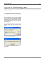
1
NV8
Socket 754 System Board
User’s Manual
4200-0440-01
Rev. 1.00
Copyright and Warranty Notice
The information in this document is subject to change without notice and does not
represent a commitment on part of the vendor, who assumes no liability or
responsibility for any errors that may appear in this manual.
No warranty or representation, either expressed or implied, is made with respect to the
quality, accuracy or fitness for any particular part of this document. In no event shall
the manufacturer be liable for direct, indirect, special, incidental or consequential
damages arising from any defect or error in this manual or product.
Product names appearing in this manual are for identification purpose only and
trademarks and product names or brand names appearing in this document are the
property of their respective owners.
This document contains materials protected under International Copyright Laws. All
rights reserved. No part of this manual may be reproduced, transmitted or transcribed
without the expressed written permission of the manufacturer and authors of this
manual.
If you do not properly set the motherboard settings, causing the motherboard to
malfunction or fail, we cannot guarantee any responsibility.
NV8
Table of Contents
Chapter 1.
1-1.
1-2.
Chapter 2.
2-1.
2-2.
2-3.
2-4.
Hardware Setup.................................................................... 2-1
Install The Motherboard...........................................................................2-1
Install CPU, Heatsink and Fan Assembly................................................2-2
Install System Memory ............................................................................2-4
Connectors, Headers and Switches ..........................................................2-5
(1). ATX Power Input Connectors ........................................................2-5
(2). FAN Power Connectors .................................................................2-6
(3). CMOS Memory Clearing Header ..................................................2-7
(4). Additional USB Port Headers ........................................................2-8
(5). Front Panel Switches & Indicators Headers ..................................2-9
(6). Wake-up Header...........................................................................2-10
(7). Front Panel Audio Connection Header ........................................2-11
(8). Internal Audio Connectors ...........................................................2-12
(9). PCI Express x16 Slot ...................................................................2-13
(10). PCI Express x1 Slots....................................................................2-14
(11). Floppy and IDE Disk Drive Connectors ......................................2-15
(12). Serial ATA Connectors .................................................................2-16
(13). Status Indicators...........................................................................2-17
(14). Back Panel Connectors ................................................................2-18
Chapter 3.
3-1.
3-2.
3-3.
3-4.
3-5.
3-6.
3-7.
3-8.
3-9.
Introduction .......................................................................... 1-1
Features & Specifications ........................................................................1-1
Layout Diagram .......................................................................................1-3
BIOS Setup............................................................................ 3-1
SoftMenu Setup........................................................................................3-2
Standard CMOS Features.........................................................................3-4
Advanced BIOS Features.........................................................................3-7
Advanced Chipset Features......................................................................3-9
Integrated Peripherals ............................................................................3-12
Power Management Setup .....................................................................3-16
PnP/PCI Configurations.........................................................................3-19
PC Health Status ....................................................................................3-21
Load Fail-Safe Defaults .........................................................................3-23
User’s Manual
3-10.
3-11.
3-12.
3-13.
Load Optimized Defaults .......................................................................3-23
Set Password ..........................................................................................3-23
Save & Exit Setup ..................................................................................3-23
Exit Without Saving...............................................................................3-23
Appendix A.
Install nVidia nForce Chipset Driver ............................................. A-1
Appendix B.
Install Realtek Audio Driver............................................................ B-1
Appendix C.
Install Cool’n’Quiet Driver ............................................................. C-1
Appendix D.
Install USB 2.0 Driver .....................................................................D-1
Appendix E.
ABIT EQ (The Hardware Doctor Utility) ....................................... E-1
Appendix F.
FlashMenu (BIOS Update Utility) .................................................. F-1
Appendix G.
NVRaid Floppy Disk........................................................................G-1
Appendix H.
Troubleshooting (Need Assistance?)...............................................H-1
Appendix I.
How to Get Technical Support ......................................................... I-1
NV8
Introduction
1-1
Chapter 1. Introduction
1-1. Features & Specifications
1. CPU
•
Supports AMD Socket 754 Athlon 64/Sempron Processor with 1.6GHz system bus using
Hyper Transport™ Technology
•
Supports AMD K8 CPU Cool ‘n’ Quiet Technology
2. Chipset
•
NVIDIA NF4-4X single chip
•
Integrated NVIDIA Gigabit Ethernet and NVIDIA Firewall
•
Supports NV RAID
3. Memory
•
•
•
Two 184-pin DIMM sockets
Supports DDR400 non-ECC un-buffered memory
Supports maximum memory capacity up to 2GB
4. ABIT Engineered
•
•
ABIT SoftMenu™ Technology
ABIT CPU ThermalGuard™ Technology
5. NV SATA RAID
•
Serial ATA 1.5Gb/s data transfer rate
•
Supports SATA 150 RAID 0/1/0+1
6. NV GbE LAN
•
NVIDIA Gigabit Ethernet Controller
7. NV Firewall
•
Native NVIDIA Firewall
8. Audio
•
Onboard 7.1-channel Audio CODEC
•
Optical S/PDIF Output
•
Supports auto jack sensing
9. Internal I/O Connectors
•
1 PCI Express X16 slot
•
•
•
3 PCI Express X1 slot
3x PCI slots
1x Floppy port supports up to 2.88MB
User’s Manual
1-2
Chapter 1
•
•
2x Ultra DMA 133/100/66/33 IDE connectors
4x SATA 150 connectors
•
•
3x USB 2.0 headers
1x CD-IN header
10. Back Panel I/O
•
•
•
•
•
•
1x PS/2 keyboard, 1x PS/2 mouse
1x Parallel Port, 1x Serial Port
1 x OPT-OUT1 Connector
1x AUDIO1 connector (Rear-Left / Rear-Right, Surround-Right/Surround Right,
Center/Subwoofer)
1x AUDIO2 connector (Mic-In, Line-In, Front-Left/Front-Right)
4x USB 2.0, 1x RJ-45 LAN Connector
11. Miscellaneous
•
!
NV8
ATX form factor: 305 x 245 mm
Specifications and information contained herein are subject to change without notice.
Introduction
1-3
1-2. Layout Diagram
User’s Manual
1-4
NV8
Chapter 1
Hardware Setup
2-1
Chapter 2. Hardware Setup
Before the Installation: Turn off the power supply switch (fully turn off the +5V standby power), or
disconnect the power cord before installing or unplugging any connectors or add-on cards. Failing to do
so may cause the motherboard components or add-on cards to malfunction or damaged.
2-1. Install The Motherboard
Most computer chassis have a base with many mounting holes to allow motherboard to be securely
attached on and at the same time, prevented from short circuits. There are two ways to attach the
motherboard to the chassis base:
1. use with studs
2. or use with spacers
In principle, the best way to attach the board is to
use with studs. Only if you are unable to do this
should you attach the board with spacers. Line up
the holes on the board with the mounting holes on
the chassis. If the holes line up and there are
screw holes, you can attach the board with studs.
If the holes line up and there are only slots, you
can only attach with spacers. Take the tip of the
spacers and insert them into the slots. After doing
this to all the slots, you can slide the board into
position aligned with slots. After the board has been positioned, check to make sure everything is OK
before putting the chassis back on.
ATTENTION: To prevent shorting the PCB circuit, please REMOVE the metal studs or spacers if they
are already fastened on the chassis base and are without mounting-holes on the motherboard to align with.
User’s Manual
2-2
Chapter 2
2-2. Install CPU, Heatsink and Fan Assembly
Please pay attention to the following notices
before installing the CPU and heatsink/fan
assembly.
1. Always use the processor with the
Heatsink and Fan Assembly installed.
2. Do not touch the pins on the processor.
3. If you ever need to reinstall the Heatsink
and fan Assembly, please clean the
heatsink surface and apply new thermal
interface material first.
3. Lower the locking lever to the fully locked
position.
1. Pull out the socket locking lever slightly,
then lift it up.
4.
2. Align the corner with triangle mark of the
processor with the marking on the motherboard,
and then place the processor vertical down into
the socket.
NV8
Apply thermal interface material.
5. Place the heatsink and fan assembly onto
the retention frame. Match the heatsink clip
with the socket mounting lug. Hook the spring
clip to the mounting lug.
Hardware Setup
6. On the other side, push the retention clip
straight down to lock into the plastic lug on the
retention frame.
2-3
8. Attach the four-pin power plug from the
heatsink and fan assembly to the CPU FAN
connector.
For detailed information on how to install your
heatsink and fan assembly, please refer to the
instruction manual came packed with the
heatsink and fan assembly you bought.
7. Turn the cam lever to lock into the retention
frame.
User’s Manual
2-4
Chapter 2
2-3. Install System Memory
This system board provides two 184-pin DDR DIMM slots for DDR 400 memory modules with memory
expansion size up to 2GB.
Bank
Memory Module
Total Memory
Bank 0, 1 (DIMM1)
256MB, 512MB, 1GB
256MB ~ 1GB
256MB, 512MB, 1GB
256MB ~ 1GB
Bank 2, 3 (DIMM2)
Total System Memory
256MB ~ 2GB
NOTE: Usually there is no hardware or BIOS setup require after adding or removing memory modules,
but you will have to clear the CMOS memory first if any memory module related problem occurs.
Power off the computer and unplug the AC power cord before installing or removing memory modules.
1.
Locate the DIMM slot on the board.
2.
Hold two edges of the DIMM module
carefully, keep away of touching its
connectors.
3.
Align the notch key on the module with the
rib on the slot.
4.
Firmly press the module into the slots until
the ejector tabs at both sides of the slot
automatically snaps into the mounting notch.
Do not force the DIMM module in with extra force as the DIMM module only fit in one direction.
5.
To remove the DIMM modules, push the two ejector tabs on the slot outward simultaneously, and
then pull out the DIMM module.
ATTENTION: Static electricity can damage the electronic components of the computer or optional
boards. Before starting these procedures, ensure that you are discharged of static electricity by touching a
grounded metal object briefly.
NV8
Hardware Setup
2-5
2-4. Connectors, Headers and Switches
Here we will show you all of the connectors, headers and switches, and how to connect them. Please read
the entire section for necessary information before attempting to finish all the hardware installation inside
the computer chassis. A complete enlarged layout diagram is shown in Chapter 1 for all the position of
connectors and headers on the board that you may refer to.
WARNING: Always power off the computer and unplug the AC power cord before adding or removing
any peripheral or component. Failing to so may cause severe damage to your motherboard and/or
peripherals. Plug in the AC power cord only after you have carefully checked everything.
(1). ATX Power Input Connectors
This motherboard provides two power connectors to connect ATX12V power supplier.
NOTE: This 24-pin power connector “ATXPWR1” is compliant to the former 20-pin type. Pay attention
to the orientation when doing so (Pin-11, 12, 23, and 24 should be left un-connected).
Note: It is recommended to connect to a power with 350W, 20A +5VDC capacity at least for heavily
loaded system, and a 2A +5VSB capacity at least for supporting wake-up features.
The auxiliary 12V power connector [ATX4P1] provides an additional power
source for devices added on PCI Express slots. It is highly recommended to
attach 12V power from the power supplier for the best system stability.
User’s Manual
2-6
Chapter 2
(2). FAN Power Connectors
These connectors each provide power to the cooling fans installed in your system.
•
CPUFAN1: CPU Fan Power Connector
•
SYSFAN1: System Fan Power Connector
•
PWRFAN1, AUXFAN1, AUXFAN2: Auxiliary Fan Power Connector
WARNING: These fan connectors are not jumpers. DO NOT place jumper caps on these connectors.
NV8
Hardware Setup
2-7
(3). CMOS Memory Clearing Header
This header uses a jumper cap to clear the CMOS memory.
•
Pin 1-2 shorted (default): Normal operation.
•
Pin 2-3 shorted: Clear CMOS memory.
WARNING: Turn the power off first (including the +5V standby power) before clearing the CMOS
memory. Failing to do so may cause your system to work abnormally or malfunction.
User’s Manual
2-8
Chapter 2
(4). Additional USB Port Headers
These headers each provide 2 additional USB 2.0 ports connection through an USB cable designed for
USB 2.0 specifications.
Pin
NV8
Pin Assignment
Pin
Pin Assignment
1
VCC
2
VCC
3
Data0 -
4
Data1 -
5
Data0 +
6
Data1 +
7
Ground
8
Ground
9
NC
10
NC
Hardware Setup
2-9
(5). Front Panel Switches & Indicators Headers
This header is used for connecting switches and LED indicators on the chassis front panel.
Watch the power LED pin position and orientation. The mark “+” align to the pin in the figure below
stands for positive polarity for the LED connection. Please pay attention to connect these headers. A
wrong orientation will only cause the LED not lighting, but a wrong connection of the switches could
cause system malfunction.
•
HLED (Pin 1, 3):
Connects to the HDD LED cable of chassis front panel.
•
RST (Pin 5, 7):
Connects to the Reset Switch cable of chassis front panel.
•
SPKR (Pin 13, 15, 17, 19):
Connects to the System Speaker cable of chassis.
•
SLED (Pin 2, 4):
Connects to the Suspend LED cable (if there is one) of chassis front panel.
•
PWR (Pin 6, 8):
Connects to the Power Switch cable of chassis front panel.
•
PLED (Pin 16, 18, 20):
Connects to the Power LED cable of chassis front panel.
User’s Manual
2-10
(6).
Chapter 2
Wake-up Header
These headers use a jumper cap to enable/disable the wake-up function.
•
PS2-PWR1:
Pin 1-2 shorted (default): Disable wake-up function support at Keyboard/Mouse port.
Pin 2-3 shorted: Enable wake-up function support at Keyboard/Mouse port.
•
USB-PWR1:
Pin 1-2 shorted: Disable wake-up function support at USB1 port.
Pin 2-3 shorted (default): Enable wake-up function support at USB1 port.
•
USB-PWR2:
Pin 1-2 shorted: Disable wake-up function support at USB2 port.
Pin 2-3 shorted (default): Enable wake-up function support at USB2 port.
•
FP-PWR1:
Pin 1-2 shorted: Disable wake-up function support at FP-USB1 port.
Pin 2-3 shorted (default): Enable wake-up function support at FP-USB1 port.
•
FP-PWR2:
Pin 1-2 shorted: Disable wake-up function support at FP-USB2 port.
Pin 2-3 shorted (default): Enable wake-up function support at FP-USB2 port.
•
FP-PWR3:
Pin 1-2 shorted: Disable wake-up function support at FP-USB2 port.
Pin 2-3 shorted (default): Enable wake-up function support at FP-USB2 port.
NV8
Hardware Setup
2-11
(7). Front Panel Audio Connection Header
This header provides the connection to audio connector at front panel.
•
To use the audio connector at front panel, remove all the jumpers on this header, and then connect
to front panel by the extension cable provided with the chassis.
•
To use the audio connector at rear panel, disconnect the extension cable, attach the jumpers back at
pin 5-6, and pin 9-10 (default setting).
Pin Pin Assignment
1 Audio Mic.
3 Audio Mic. Bias
Speaker Out
5
Right Channel
7 X
Speaker Out
9
Left Channel
Pin
2
4
6
8
10
Pin Assignment
Ground
VCC
Speaker Out Right
Channel Return
NC
Speaker Out Left
Channel Return
User’s Manual
2-12
(8). Internal Audio Connectors
This connector connects to the audio output of internal CD-ROM drive or add-on card.
NV8
Chapter 2
Hardware Setup
2-13
(9). PCI Express x16 Slot
This slot is used to attach the next generation of graphics architecture.
User’s Manual
2-14
(10). PCI Express x1 Slots
These slots are used to attach the next generation of I/O architecture.
NV8
Chapter 2
Hardware Setup
2-15
(11). Floppy and IDE Disk Drive Connectors
The FDC1 connector connects up to two floppy drives with a 34-wire, 2-connector floppy cable. Connect
the single end at the longer length of ribbon cable to the FDC1 on the board, the two connectors on the
other end to the floppy disk drives connector. Generally you need only one floppy disk drive in your
system.
NOTE: The red line on the ribbon cable must be aligned with pin-1 on both the FDC1 port and the floppy
connector.
Each of the IDE port connects up to two IDE drives at
Ultra ATA/100 mode by one 40-pin, 80-conductor, and
3-connector Ultra ATA/66 ribbon cables.
Connect the single end (blue connector) at the longer
length of ribbon cable to the IDE port of this board, the
other two ends (gray and black connector) at the shorter
length of the ribbon cable to the connectors of your hard
drives.
NOTE: Make sure to configure the “Master” and “Slave” relation before connecting two drives by one
single ribbon cable. The red line on the ribbon cable must be aligned with pin-1 on both the IDE port and
the hard-drive connector.
User’s Manual
2-16
Chapter 2
(12). Serial ATA Connectors
These connectors are provided to attach one Serial ATA device at each channel via Serial ATA cable.
NV8
Hardware Setup
2-17
(13). Status Indicators
•
LED1 (VCC): This LED lights up when the system power is on.
•
LED2 (5VSB): This LED lights up when the power supply is connected with power source.
User’s Manual
2-18
Chapter 2
(14). Back Panel Connectors
• Mouse: Connects to PS/2 mouse.
• Keyboard: Connects to PS/2 keyboard.
• LPT1: Connects to printer or other devices that support this communication protocol.
• COM1: Connects to external modem, mouse or other devices that support this communication
protocol.
• OPT-OUT1: This connector provides an S/PDIF-Out connection through optical fiber to digital
multimedia devices.
•
AUDIO1:
R.L./R.R. (Rear Left / Rear Right): Connects to the rear left and rear right channel in the 7.1
channel audio system.
S.L./S.R. (Surround Left / Surround Right): Connects to the surround left and surround right
channel in the 7.1 channel audio system.
Cen./Sub. (Center / Subwoofer): Connects to the center and subwoofer channel in the 7.1 channel
audio system.
•
AUDIO2:
Mic-In: Connects to the plug from external microphone.
Line-In: Connects to the line out from external audio sources.
Line-Out: Connects to the front left and front right channel in the 7.1-channel or regular 2-channel
audio system.
• LAN: Connects to Local Area Network.
• USB1/USB2: Connects to USB devices such as scanner, digital speakers, monitor, mouse,
keyboard, hub, digital camera, joystick etc.
NV8
BIOS Setup
3-1
Chapter 3. BIOS Setup
This motherboard provides a programmable EEPROM that you can update the BIOS utility. The BIOS
(Basic Input/Output System) is a program that deals with the basic level of communication between
processor and peripherals. Use the BIOS Setup program only when installing motherboard, reconfiguring
system, or prompted to “Run Setup”. This chapter explains the Setup Utility of BIOS utility.
After powering up the system, the BIOS message appears on the screen, the memory count begins, and
then the following message appears on the screen:
PRESS DEL TO ENTER SETUP
If this message disappears before you respond, restart the system by pressing <Ctrl> + <Alt> + <Del>
keys, or by pressing the Reset button on computer chassis. Only when it failed by these two methods can
you restart the system by powering it off and then back on.
After pressing <Del> key, the main menu screen appears.
Phoenix – AwardBIOS CMOS Setup Utility
► SoftMenu Setup
► PC Health Status
► Standard CMOS Features
Load Fail-Safe Defaults
► Advanced BIOS Features
Load Optimized Defaults
► Advanced Chipset Features
Set Password
► Integrated Peripherals
Save & Exit Setup
► Power Management Setup
Exit Without Saving
► PnP/PCI Configurations
Esc : Quit
F10 : Save & Exit Setup
↑ ↓ → ← : Select Item
(NF-CK804-6K61FA1DC-00)
Change CPU’s Clock & Voltage
NOTE: In order to increase system stability and performance, our engineering staffs are constantly
improving the BIOS menu. The BIOS setup screens and descriptions illustrated in this manual are for
your reference only and may not completely match what you see on your screen.
In the BIOS Setup main menu, you can see several options. We will explain these options step by step in
the following pages of this chapter, but let us first see a short description of the function keys you may
use here.
Esc:
Press this button to quit the BIOS Setup.
↑↓← →:
Press these buttons to choose, in the main menu, the option you want to confirm or to modify.
F10:
When you have completed the setup of BIOS parameters, press this button to save these parameters and
to exit the BIOS Setup menu.
User’s Manual
3-2
Chapter 3
3-1. SoftMenu Setup
The SoftMenu utility is ABIT’s exclusive and ultimate solution in programming the CPU operating speed.
All the parameters regarding CPU FSB speed, multiplier factor, the AGP & PCI clock, and even the CPU
core voltage are all available at your fingertips.
Brand Name
Frequency
Phoenix – AwardBIOS CMOS Setup Utility
SoftMenu Setup
: AMD Athlon(tm) 64 Processor 3400+
: 2200MHz
CPU Operating Speed
X - CPU FSB Clock(MHz)
X - Multiplier Factor
X - PCIE Clock
X
X
X
X
X
Voltages Control
- CPU Core Voltage
- DDR RAM Voltage
- DDR Ref Voltage
- nForce4 Voltage
- Hypertransport Voltage
Item Help
Default
200
AUTO
100Mhz
Default
1.500 V
2.60 V
Default
1.50 V
Default
↑↓:Move Enter:Select +/-/PU/PD:Value F10:Save ESC:Exit F1:General Help
F5: Previous Values F6: Fail-Safe Defaults F7: Optimized Defaults
Brand Name:
This item displays the CPU model name.
Frequency:
This item displays the CPU internal clock speed.
CPU Operating Speed:
This item displays the CPU operating speed according to the type and speed of your CPU. You can also
select the [User Define] option to enter the manual option.
User Define:
WARNING: The wrong settings of the multiplier and external clock in certain circumstances may cause
CPU damage. Setting the working frequency higher than the PCI chipset or processor specs, may cause
abnormal memory module functioning, system hangs, hard disk drive data lose, abnormal functioning of
the VGA card, or abnormal functioning with other add-on cards. Using non-specification settings for your
CPU is not the intention of this explanation. These should be used for engineering testing, not for normal
applications.
There will be no guaranty for the settings beyond specification, any damage of any component on this
motherboard or peripherals result therein is not our responsibility.
NV8
BIOS Setup
!
3-3
CPU FSB Clock(MHz):
This item selects the external clock frequency. Due to the specification limit of the CPU you installed, the
speed you set over its standard bus speed is supported, but not guaranteed.
!
Multiplier Factor:
This item displays the multiplier factor for the CPU you installed.
!
PCIE Clock:
This item selects the PCI Express frequency.
Voltage Control:
This option allows you to switch between the default and user-defined voltages. Leave this setting to
default unless the current voltage setting cannot be detected or is not correct. The option “User Define”
enables you to select the following voltages manually.
!
CPU Core Voltage:
This item selects the CPU core voltage.
!
DDR RAM Voltage:
This item selects the voltage for DRAM slot.
!
DDR Ref Voltage:
This item selects the reference voltage needed for DRAM slot to increase its conformity.
!
nForce4 Voltage:
This item selects the NB voltage.
!
HyperTransport Voltage:
This item selects the voltage for LDT Bus.
ATTENTION: A wrong voltage setting may cause the system unstable or even damage the CPU. Please
leave it to default settings unless you are fully aware of its consequences.
User’s Manual
3-4
Chapter 3
3-2. Standard CMOS Features
This section contains the basic configuration parameters of the BIOS. These parameters include date,
hour, VGA card, FDD and HDD settings.
Phoenix – AwardBIOS CMOS Setup Utility
Standard CMOS Features
Date (mm:dd:yy)
Thu. Jan 1 2005
Time (hh:mm:ss)
12 : 34 : 56
►
►
►
►
►
►
►
►
IDE
IDE
IDE
IDE
IDE
IDE
IDE
IDE
Channel
Channel
Channel
Channel
Channel
Channel
Channel
Channel
1
1
2
2
3
4
5
6
Master
Slave
Master
Slave
Master
Master
Master
Master
Item Help
None
None
None
None
None
None
None
None
Drive A
Drive B
Floppy 3 Mode Support
Halt On
1.44M, 3.5 in.
None
Disabled
All, But keyboard
Base Memory
Extended Memory
Total Memory
640K
1046520K
1047552K
↑↓:Move Enter:Select +/-/PU/PD:Value F10:Save ESC:Exit F1:General Help
F5: Previous Values F6: Fail-Safe Defaults F7: Optimized Defaults
Date (mm:dd:yy):
This item sets the date you specify (usually the current date) in the format of [Month], [Date], and [Year].
Time (hh:mm:ss):
This item sets the time you specify (usually the current time) in the format of [Hour], [Minute], and
[Second].
NV8
BIOS Setup
#
3-5
IDE Channel 1 Master/Slave, IDE Channel 2 Master/Slave, IDE Channel
3 Master, IDE Channel 4 Master, IDE Channel 5 Master, IDE Channel 6
Master:
Click <Enter> key to enter its submenu:
Phoenix – AwardBIOS CMOS Setup Utility
IDE Channel 1 Master
IDE HDD Auto-Detection
Press Enter
IDE Channel 1 Master
Access Mode
Auto
Auto
Capacity
0 MB
Cylinder
Head
Precomp
Landing Zone
Sector
0
0
0
0
0
Item Help
↑↓:Move Enter:Select +/-/PU/PD:Value F10:Save ESC:Exit F1:General Help
F5: Previous Values F6: Fail-Safe Defaults F7: Optimized Defaults
IDE HDD Auto-Detection:
This item allows you to detect the parameters of IDE drives by pressing <Enter> key. The parameters will
be shown on the screen automatically.
IDE Channel 1 Master/Slave, IDE Channel 2 Master/Slave, IDE Channel 3 Master, IDE Channel 4
Master, IDE Channel 5 Master, IDE Channel 6 Master:
When set to [Auto], the BIOS will automatically check what kind of IDE drive you are using. If you want
to define your own drive by yourself, set it to [Manual] and make sure you fully understand the meaning
of the parameters. Please refer to the instruction manual provided by the device’s manufacturer to get the
setting right.
Access Mode:
This item selects the mode to access your IDE devices. Leave this item to its default [Auto] setting to
detect the access mode of your HDD automatically.
Capacity:
This item displays the approximate capacity of the disk drive. Usually the size is slightly greater than the
size of a formatted disk given by a disk-checking program.
Cylinder:
This item configures the number of cylinders.
User’s Manual
3-6
Chapter 3
Head:
This item configures the number of read/write heads.
Precomp:
This item displays the number of cylinders at which to change the write timing.
Landing Zone:
This item displays the number of cylinders specified as the landing zone for the read/write heads.
Sector:
This item configures the number of sectors per track.
#
Back to Standard CMOS Features Setup Menu:
Drive A & Drive B:
This item sets the type of floppy drives (usually only Drive A) installed.
Floppy 3 Mode Support:
This item allows you to use “3 Mode Floppy Drive” in Japanese computer system by selecting drive A, B,
or both. Leave this item to its default [Disabled] setting if you are not using this Japanese standard floppy
drive.
Halt On:
This item determines whether the system stops if an error is detected during system boot-up.
[All Errors]: The system-boot will stop whenever the BIOS detect a non-fatal error.
[No Errors]: The system-boot will not stop for any error detected.
[All, But Keyboard]: The system-boot will stop for all errors except a keyboard error.
[All, But Diskette]: The system-boot will stop for all errors except a diskette error.
[All, But Disk/Key]: The system-boot will stop for all errors except a diskette or keyboard error.
Base Memory:
This item displays the amount of base memory installed in the system. The value of the base memory is
typically 640K for system with 640K or more memory size installed on the motherboard.
Extended Memory:
This item displays the amount of extended memory detected during system boot-up.
Total Memory:
This item displays the total memory available in the system.
NV8
BIOS Setup
3-7
3-3. Advanced BIOS Features
Phoenix – AwardBIOS CMOS Setup Utility
Advanced BIOS Features
Quick Power on Self Test
Enabled
► Hard Disk Boot Priority
Press Enter
First Boot Device
Floppy
Second Boot Device
Hard Disk
Third Boot Device
CDROM
Boot Other Device
Enabled
Boot Up Floppy Seek
Disabled
Boot Up NumLock Status
On
Security Option
Setup
MPS Version Ctrl For OS
1.4
OS Select For DRAM > 64MB
None-OS2
Delay For HDD (Secs)
0
Full Screen Logo Show
Enabled
Item Help
↑↓:Move Enter:Select +/-/PU/PD:Value F10:Save ESC:Exit F1:General Help
F5: Previous Values F6: Fail-Safe Defaults F7: Optimized Defaults
Quick Power On Self Test:
When set to [Enabled], this item speeds up the Power On Self Test (POST) after powering on the system.
The BIOS shorten or skip some check during the POST.
Hard Disk Boot Priority:
This item selects the hard disks booting priority. By pressing <Enter> key, you can enter its submenu
where the hard disks detected can be selected for the booting sequence to boot up system.
This item functions only when there is the option of [Hard Disk] in any one of the First/Second/Third
Boot Device items.
First Boot Device / Second Boot Device / Third Boot Device / Boot Other Device:
Select the drive to boot first, second and third in the [First Boot Device], [Second Boot Device], and
[Third Boot Device] items respectively. The BIOS will boot the operating system according to the
sequence of the drive selected. Set [Boot Other Device] to [Enabled] if you wish to boot from another
device other than these three items.
Boot Up Floppy Seek:
When the computer boots up, the BIOS detects if the system has a FDD or not. When this item is set to
Enabled, if the BIOS detects no floppy drive, it will display a floppy disk drive error message. If this item
is disabled, the BIOS will skip this test. The default setting is Disabled.
Boot Up NumLock Status:
This item determines the default state of the numeric keypad at system booting up.
[On]: The numeric keypad functions as number keys.
[Off]: The numeric keypad functions as arrow keys.
User’s Manual
3-8
Chapter 3
Security Option:
This item determines when the system will prompt for password - every time the system boots or only
when it enters the BIOS setup.
[Setup]: The password is required only when accessing the BIOS Setup.
[System]: The password is required each time the computer boots up.
To disable security, select Set Password at main menu and then you will be asked to enter the password.
Do not type anything and just press the <Enter> key and it will disable security. Once security is disabled,
the system will boot and you can enter the BIOS setup menu freely.
NOTE: Don’t forget your password. If you forget the password, you will have to open the computer case
and clear all information in the CMOS before you can start up the system. But by doing this, you will
have to reset all previously set options.
MPS Version Ctrl For OS:
This item specifies which version of MPS (Multi-Processor Specification) this motherboard will use.
Leave this item to its default setting.
OS Select For DRAM > 64MB:
This item allows you to access the memory that is over 64MB in OS/2. Leave this item to its default
[Non-OS2] setting for operating system other than OS/2.
Delay For HDD (Secs):
This item allows the BIOS to support some old or special IDE devices by prolonging this delay time. A
larger value will give more delay time to the device for which to initialize and to prepare for activation.
Full Screen LOGO Show:
This item determines to show the full screen logo when booting.
NV8
BIOS Setup
3-9
3-4. Advanced Chipset Features
Phoenix – AwardBIOS CMOS Setup Utility
Advanced Chipset Features
HT Frequency
AUTO
► DRAM Configuration
Press Enter
SSE/SSE2 Instructions
Enable
System BIOS Cachable
Disable
Item Help
↑↓:Move Enter:Select +/-/PU/PD:Value F10:Save ESC:Exit F1:General Help
F5: Previous Values F6: Fail-Safe Defaults F7: Optimized Defaults
HT Frequency:
This item selects the LDT Bus Frequency.
#
DRAM Configuration:
Click <Enter> key to enter its submenu:
Phoenix – AwardBIOS CMOS Setup Utility
DRAM Configuration
DRAM Timing Selectable
Auto
X - DRAM Clock
Auto
X - CAS latency Time
Auto
X - Row Cycle Time
Auto
X - Row Refresh Cycle Time
Auto
X - Min RAS# Active time
Auto
X - RAS# to CAS# delay
Auto
X - RAS# Precharge Time
Auto
X - RAS# to RAS# delay
Auto
X - Write Recovery Time
Auto
X - Write to Read Delay
Auto
X - Read to Write Delay
Auto
X - DRAM Command rate
Auto
X - Bank Interleaving
Enabled
X - Burst Length
4 beats
MTRR mapping mode
Continuous
32 bit Dram Memory Hole
Auto
Item Help
↑↓:Move Enter:Select +/-/PU/PD:Value F10:Save ESC:Exit F1:General Help
F5: Previous Values F6: Fail-Safe Defaults F7: Optimized Defaults
DRAM Timing Selectable:
This item selects the DRAM timing mode. When set to “By SPD”, the BIOS will read the DRAM module
SPD data and automatically set to the values stored in it. Leave this item to its default “Auto” setting.
User’s Manual
3-10
!
Chapter 3
DRAM Clock:
This item sets the DRAM clock of your DRAM module. The system may be unstable or unable to boot up
if your DRAM module does not support the clock you set.
When set to [By SPD], the BIOS will read the DRAM module SPD data and automatically set the DRAM
clock by the value stored in it.
!
CAS Latency Time:
You can select SDRAM CAS (Column Address Strobe) latency time according your SDRAM
specification.
!
Row Cycle Time:
This item specifies the RAS# active to RAS# active time or auto refresh time of the same bank.
!
Row Refresh Cycle Time:
This item specifies the auto refresh active to RAS# active time or RAS# auto refresh time.
!
Min. RAS# Active Time:
This item specifies the minimum RAS# active time.
!
RAS# to CAS# Delay:
This item specifies the RAS# active to CAS# read write delay time to the same bank.
!
RAS# Precharge Time:
This item specifies the RAS# precharge time.
!
RAS# to RAS# Delay:
This item specifies the RAS# active to RAS# active delay time of different bank.
!
Write Recovery Time:
This item specifies the time measured from the last write datum is safely registered by the DRAM.
!
Write to Read Delay:
This item specifies the time measured from the rising edge following the last non-masked data strobe to
the rising edge of the next read command.
!
Read to Write Delay:
This item specifies the read to write delay.
!
DRAM Command Rate:
When the host (northbridge) locates the desired memory address, it then processes the wait state of
commands.
!
Bank Interleaving:
Depending on your SDRAM module structure, the 4-Way setting can offer the best performance. If you
choose the wrong setting, the computer system will not run in a stable manner. For detailed information
on your SDRAM module, please ask your SDRAM module manufacturer.
NV8
BIOS Setup
!
3-11
Burst Length
DDR SDRAM modules provide a Burst mode that means an auto precharge function for programmable
READ or WRITE burst lengths of 2, 4 or 8 locations.
This means that if we set burst length to 8, the address bus will access 8 bytes each cycle to precharge,
etc.
MTRR mapping mode
The item selects the MTRR mapping mode. The MTRR (Memory-Type and Range Registers) controls
the access and cacheability of memory regions in the processor.
32 bit Dram Memory Hole:
This item selects the method to remap the 32 bit Dram memory hole. Leave this item to its default “Auto”
Setting.
#
Back to Advanced Chipset Features Setup Menu:
SSE/SSE2 Instructions:
This item allows you to Enable or Disable the SSE/SSE2 (Streaming SIMD Extensions) instruction set.
The default setting is Enabled.
System BIOS Cacheable:
Two options are available: Disabled or Enabled. When you select Enabled, you get faster system BIOS
executing speed via the L2 cache.
User’s Manual
3-12
Chapter 3
3-5. Integrated Peripherals
Phoenix – AwardBIOS CMOS Setup Utility
Integrated Peripherals
► IDE/RAID Function
Press Enter
Init Display First
PCI Slot
OnChip USB
V1.1+V2.0
- USB Keyboard Support
Disable
- USB Mouse Support
Disable
OnChip Audio Controller
Auto
OnChip LAN Controller
Auto
- Onboard LAN Boot ROM
Disabled
Onboard FDC Controller
Enabled
Onboard Serial Port 1
3F8/IRQ4
Onboard Parallel Port
378/IRQ7
Parallel Port Mode
SPP
X EPP Mode Select
EPP1.7
X ECP Mode Use DMA
3
IDE HDD Block Mode
Enabled
Item Help
↑↓:Move Enter:Select +/-/PU/PD:Value F10:Save ESC:Exit F1:General Help
F5: Previous Values F6: Fail-Safe Defaults F7: Optimized Defaults
#
IDE/RAID Function
Click <Enter> key to enter its submenu:
Phoenix – AwardBIOS CMOS Setup Utility
IDE/RAID Fuction Setup
► IDE Function Setup
Press Enter
► RAID Config
Press Enter
Item Help
↑↓:Move Enter:Select +/-/PU/PD:Value F10:Save ESC:Exit F1:General Help
F5: Previous Values F6: Fail-Safe Defaults F7: Optimized Defaults
NV8
BIOS Setup
#
3-13
IDE Function Setup:
Click <Enter> key to enter its submenu:
Phoenix – AwardBIOS CMOS Setup Utility
IDE Fuction Setup
OnChip IDE Channel 1
Enabled
OnChip IDE Channel 2
Enabled
IDE DMA transfer access
Enabled
Serial-ATA 1/2
Enabled
Serial-ATA 3/4
Enabled
IDE Prefetch Mode
Enabled
Item Help
↑↓:Move Enter:Select +/-/PU/PD:Value F10:Save ESC:Exit F1:General Help
F5: Previous Values F6: Fail-Safe Defaults F7: Optimized Defaults
OnChip IDE Channel 1/ OnChip IDE Channel 2:
This item allows you to enable or disable the primary (IDE1) and secondary (IDE2) IDE controller. Select
[Disabled] if you want to add a different hard drive controller.
IDE DMA transfer access:
This item selects the DMA mode for devices connected through IDE channels.
Serial-ATA 1/2, Serial ATA 3/4:
This item enables or disables the on-chip SATA controller.
IDE Prefetch Mode:
Two options are available: Disabled or Enabled. The default setting is Enabled. The onboard IDE drive
interfaces support IDE prefetching for faster drive accesses. If you install a primary and/or secondary
add-in IDE interface, set this field to Disabled if the interface does not support prefetching.
User’s Manual
3-14
#
Chapter 3
RAID Config:
Click <Enter> key to enter its submenu:
Phoenix – AwardBIOS CMOS Setup Utility
RAID Config
RAID Enable
Diaabled
X - IDE 1 Master RAID
Disabled
X - IDE 1 Slave RAID
Disabled
X - IDE 2 Master RAID
Disabled
X - IDE 2 Slave RAID
Disabled
X - Serial-ATA 1 RAID
Disabled
X - Serial-ATA 2 RAID
Disabled
X - Serial-ATA 3 RAID
Disabled
X - Serial-ATA 4 RAID
Disabled
Item Help
↑↓:Move Enter:Select +/-/PU/PD:Value F10:Save ESC:Exit F1:General Help
F5: Previous Values F6: Fail-Safe Defaults F7: Optimized Defaults
RAID Enable:
This item allows you to enable or disable the IDE RAID function.
!
IDE 1/2 Master/Slave RAID, Serial ATA 1/2/3/4 RAID:
Select the disks that you want to use as RAID disks.
#
Back to Integrated Peripherals Setup Menu:
Init Display First:
This item selects which display slot to be initialized first when the system boots.
[PCI Slot]: When the system boots, it will first initialize PCI.
[PCIEx]: When the system boots, it will first initialize PCIE.
OnChip USB:
Three options are available: Disabled $ V1.1+V2.0 $ V1.1. The default setting is V1.1+V2.0. If you
choose to disable this item, the “USB Memory Type” “USB Keyboard Support” and “USB Mouse
Support” items will not be able to select in Integrated Peripherals menu.
!
USB Keyboard Support:
This item allows you to select [Enabled] for using USB keyboard in DOS environment, or [Disabled] in
OS environment.
!
USB Mouse Support:
This item allows you to select [Enabled] for using USB mouse in DOS environment, or [Disabled] in OS
environment.
NV8
BIOS Setup
3-15
OnChip Audio Controller:
This option enables or disables the audio controller.
OnChip LAN Controller:
This option enables or disables the LAN controller.
!
Onboard LAN Boot ROM:
This item allows you to use the boot ROM (instead of a disk drive) to boot-up the system and access the
local area network directly.
Onboard FDC Controller:
Two options are available: Enabled and Disabled. The default setting is Enabled. You can enable or
disable the onboard FDC controller.
Onboard Serial Port 1:
This is used to specify the I/O address and IRQ of Serial Port 1. Six options are available: Disabled $
3F8/IRQ4 $ 2F8/IRQ3 $ 3E8/IRQ4 $ 2E8/IRQ3 $ AUTO. The default setting is 3F8/IRQ4.
Onboard Parallel Port:
Sets the I/O address and IRQ of the onboard parallel port. Four options are available: Disabled $
378/IRQ7 $ 278/IRQ5 $ 3BC/IRQ7. Default setting is 378/IRQ7.
Parallel Port Mode:
Four options are available: SPP $ EPP $ ECP $ ECP+EPP. The default setting is SPP mode.
!
EPP Mode Select:
Two options are available: EPP1.7 $ EPP1.9. The default setting is EPP 1.7 When the mode selected for
the parallel port mode is EPP, the two EPP version options are available.
!
ECP Mode Use DMA:
Two options are available: 1 $ 3. The default setting is 3. When the mode selected for the parallel port
mode is ECP, the DMA channel selected can be Channel 1 or Channel 3.
IDE HDD Block Mode:
This item enables or disables the IDE HDD Block Mode.
User’s Manual
3-16
Chapter 3
3-6. Power Management Setup
X
X
X
X
Phoenix – AwardBIOS CMOS Setup Utility
Power Management Setup
ACPI Suspend Type
S3(Suspend-to-RAM)
- USB Resume from S3
Disabled
Power Button Function
Instant-Off
Wake-Up by PME# of PCI
Disabled
Wake-Up by Ring
Disabled
Wake-Up by OnChip LAN
Enabled
Wake-Up by Alarm
Disabled
- Date(of Month) Alarm
0
- Time (hh:mm:ss) Alarm
0 : 0 : 0
POWER ON Function
BUTTON ONLY
- KB Power ON Password
Enter
- Hot Key Power ON
Ctrl-F1
Restore on AC Power Loss
Power Off
Item Help
↑↓:Move Enter:Select +/-/PU/PD:Value F10:Save ESC:Exit F1:General Help
F5: Previous Values F6: Fail-Safe Defaults F7: Optimized Defaults
ACPI Suspend Type:
This item selects the type of Suspend mode.
[S1(PowerOn-Suspend)]: Enables the Power On Suspend function.
[S3(Suspend-To-RAM)]: Enables the Suspend to RAM function.
!
USB Resume from S3:
Two options are available: Disabled or Enabled. The default setting is Disabled. When set to Enabled,
any event related to onchip USB will power on the system. This item can be configured only if the item
“ACPI Suspend Type” is set to [S3(STR)].
Power Button Function:
Two options are available: Delay 4 Sec or Instant-Off. The default setting is Instant-Off. It is activated
when the user presses the power button for more than four seconds while the system is in the working
state, then the system will transition to the soft-off (Power off by software). This is called the power
button over-ride.
Wakeup by PME# of PCI:
Two options are available: Disabled or Enabled. The default setting is Enabled. When set to Enabled, any
event related to PCI cards (PME) will power on the system.
Wake-Up by Ring:
Two options are available: Disabled or Enabled. The default setting is Disabled. When set to Enabled,
any event affecting from Modem Ring will awaken a system that has powered down.
NV8
BIOS Setup
3-17
Wake-Up by OnChip LAN:
When set to [Enabled], you can remotely wake up a PC in Soft-Off condition via a LAN card that support
the wake up function.
Wake-Up by Alarm:
Two options are available: Disabled or Enabled. The default setting is Disabled. When set to Enabled,
you can set the date and time at which the RTC (real-time clock) alarm awakens the system from Suspend
mode.
!
Date (of Month) Alarm/ Time (hh:mm:ss) Alarm:
You can set the Date (month) Alarm and Time Alarm (hh:mm:ss). Any event occurring will awaken a
system that has powered down.
Power On Function:
This item selects the way you want your system to power on.
[Password]: Use a password to power on the system, select this option then press <Enter>. Enter your
password. You can enter up to 5 characters. Type in exactly the same password to confirm, and then press
<Enter>.
[Hot KEY]: Use any of the function keys between <F1> to <F12> to power on the system.
[Mouse Left]: Double click the mouse left button to power on the system.
[Mouse Right]: Double click the mouse right button to power on the system.
[Any KEY]: Use any keyboard key to power on the system.
[BUTTON ONLY]: Use only the power button to power on the system.
[Keyboard 98]: Use the power-on button on the “Keyboard 98” compatible keyboard to power on the
system.
!
KB Power On Password:
This item sets the password required in order to power on your computer. Once the password has been set,
you can only power on the system by inputting the password.
!
Hot Key Power On:
Fifteen options are available: Ctrl+F1 ~ Ctrl+F12, Power, Wake and Any Key. The default setting is
Ctrl+F1. You can choose the hot key you want to turn on computer power.
User’s Manual
3-18
Chapter 3
Restore on AC Power Loss:
This item selects the system action after an AC power failure.
[Power Off]: When power returns after an AC power failure, the system’s power remains off. You must
press the Power button to power-on the system.
[Power On]: When power returns after an AC power failure, the system’s power will be powered on
automatically.
[Last State]: When power returns after an AC power failure, the system will return to the state where you
left off before power failure occurs. If the system’s power is off when AC power failure occurs, it will
remain off when power returns. If the system’s power is on when AC power failure occurs, the system
will power-on when power returns.
NV8
BIOS Setup
3-19
3-7. PnP/PCI Configurations
Phoenix – AwardBIOS CMOS Setup Utility
PnP/PCI Configurations
Resources Controlled By
Auto(ESCD)
x IRQ Resources
Press Enter
PCI/VGA Pallete Snoop
PIRQ_0 Use IRQ No.
PIRQ_1 Use IRQ No.
PIRQ_2 Use IRQ No.
PIRQ_3 Use IRQ No.
Item Help
Disbaled
Auto
Auto
Auto
Auto
** PCI Express relative items **
Maximum Payload Size
4096
↑↓:Move Enter:Select +/-/PU/PD:Value F10:Save ESC:Exit F1:General Help
F5: Previous Values F6: Fail-Safe Defaults F7: Optimized Defaults
Resources Controlled By:
This item configures all of the boot and Plug-and-Play compatible devices.
[Auto(ESCD)]: The system will automatically detect the settings.
[Manual]: Choose the specific IRQ resources in the “IRQ Resources” menu.
User’s Manual
3-20
#
Chapter 3
IRQ Resources:
Click <Enter> key to enter its submenu:
This item sets each system interrupt to either [PCI Device] or [Reserved].
Phoenix – AwardBIOS CMOS Setup Utility
PnP/PCI Configurations
IRQ-3 assigned to
PCI Device
IRQ-4 assigned to
PCI Device
IRQ-5 assigned to
PCI Device
IRQ-7 assigned to
PCI Device
IRQ-9 assigned to
PCI Device
IRQ-10 assigned to
PCI Device
IRQ-11 assigned to
PCI Device
IRQ-12 assigned to
PCI Device
↑↓:Move Enter:Select +/-/PU/PD:Value F10:Save ESC:Exit F1:General Help
F5: Previous Values F6: Fail-Safe Defaults F7: Optimized Defaults
#
Back to PnP/PCI Configurations Setup Menu:
PCI/VGA Palette Snoop:
This item determines whether the MPEG ISA/VESA VGA cards can work with PCI/VGA or not.
[Disabled]: MPEG ISA/VESA VGA cards do not work with PCI/VGA.
[Enabled]: MPEG ISA/VESA VGA cards work with PCI/VGA.
PIRQ_0 Use IRQ No. ~ PIRQ 3 Use IRQ No.:
This item specifies the IRQ number manually or automatically for the devices installed on PCI slots.
Maximum Payload Size:
This item sets the maximum TLP payload size for the PCI Express devices.
NV8
BIOS Setup
3-21
3-8. PC Health Status
You can set the warning temperature for your computer system, and you can check the fan speeds and
power supply voltages of your computer system. The features are useful for monitoring all the important
parameters within your computer system. We call it the PC Health Status.
Phoenix – AwardBIOS CMOS Setup Utility
PC Health Status
FAN Fail Alarm Selectable
Disabled
Item Help
Shutdown when FAN Fail
Disabled
CPU FanEQ Speed Control
Disabled
- CPU FAN Active Temperature
70
Shutdown Temperature
Disabled
CPU Warning Temperature
Disabled
CPU Temperature
48OC/118OF
System Temperature
42OC/107OF
CPU FAN Speed
3125 RPM
NB FAN Speed
4963 RPM
SYS FAN Speed
0 RPM
CPU Core Voltage
1.52 V
DDR Voltage
2.67 V
ATX +3.3V
3.31 V
ATX +5V
5.08 V
ATX +12V
11.97 V
CK804 CORE Voltage
1.56 V
Hyper Transport Voltage
1.23 V
+3V Dual
2.27 V
↑↓:Move Enter:Select +/-/PU/PD:Value F10:Save ESC:Exit F1:General Help
F5: Previous Values F6: Fail-Safe Defaults F7: Optimized Defaults
FAN Fail Alarm Selectable:
This item selects the fan that will be monitored for malfunction.
Shutdown When Fan Fail:
The system will be shut down if the selected fan is not running.
CPU FanEQ Speed Control:
This item allows you to control the CPU fan speed down to a specific percentage.
When set to a specific percentage, the CPU fan speed will run at the percentage you set in this item if the
temperature limit set in the item “Active Temperature” is not exceeded.
The CPU fan speed will run at 100% regardless of what the percentage you set in this item if the
temperature limit set in the item “Active Temperature” is exceeded.
!
CPU FAN Active Temperature:
This item sets the temperature limit that would activate the function of “CPU FanEQ Speed Control”
option.
Shutdown Temperature:
You can set the processor shutdown temperature here. If the processor temperature exceeds the settings
value, system will force to shutdown to protect the processor not overheat.
User’s Manual
3-22
Chapter 3
CPU Warning Temperature:
This item lets you select the temperature at which you want the system to send out a warning message to
the PC speakers of when the temperature goes beyond either limit. You can select the temperatures you
want.
All Voltages, Fans Speed and Thermal Monitoring:
These unchangeable items list the current status of the CPU and environment temperatures, fan speeds,
and system power voltage.
NOTE: The hardware monitoring features for temperatures, fans and voltages will occupy the I/O
address from 294H to 297H. If you have a network adapter, sound card or other add-on cards that might
use those I/O addresses, please adjust your add-on card I/O address to avoid using these addresses.
NV8
BIOS Setup
3-23
3-9. Load Fail-Safe Defaults
This option loads the BIOS default values for the most stable, minimal-performance system operations.
3-10. Load Optimized Defaults
This option loads the BIOS default values that are factory settings for optimal-performance system
operations.
3-11. Set Password
This option protects the BIOS configuration or restricts access to the computer itself.
3-12. Save & Exit Setup
This option saves your selections and exits the BIOS setup menu.
3-13. Exit Without Saving
This option exits the BIOS setup menu without saving any change.
User’s Manual
3-24
NV8
Chapter 3
Install nVidia nForce Chipset Driver
A-1
Appendix A. Install nVidia nForce Chipset Driver
NOTE: Please install this NVIDIA nForce Chipset driver first after having installed the Windows
operating system.
The installation procedures and screen shots in
this section are based on the Windows XP
operating system. For other operating systems,
please follow the on-screen instructions.
Insert the Driver & Utility CD into the
CD-ROM drive. It should execute the
installation program automatically. If not,
double-click the executable file at the main
directory of this CD to enter the installation
menu.
After entering the installation menu, move your
curser to [Drivers] tab. Click [nVidia nForce
Chipset Driver[32bit]]. The following screen
appears.
1.
Click [Next].
2.
Click [Next].
3.
Click [Next].
4.
Click [Yes].
User’s Manual
A-2
5.
Appendix A
Click [Yes].
9.
6.
Click [Next].
Click [Next].
10. Choose [Yes, I want to restart my computer
now.], and click [Finish] to complete setup.
7.
Click [Next].
8.
Click [Next].
NV8
Install Realtek Audio Driver
B-1
Appendix B. Install Realtek Audio Driver
The installation procedures and screen shots in
this section are based on Windows XP operating
system. For those of other OS, please follow its
on-screen instruction.
Insert the Driver & Utility CD into CD-ROM
drive, it should execute the installation program
automatically. If not, double-click the execution
file at the main directory of this CD to enter the
installation menu.
After entering the installation menu, move your
curser to [Drivers] tab. Click [Realtek Audio
Driver]. The following screen appears.
1.
Click [Next].
2. Choose [Yes, I want to restart my computer
now.], and click [Finish] to complete setup.
User’s Manual
B-2
NV8
Appendix B
Install Cool’n’Quiet Driver
C-1
Appendix C. Install Cool’n’Quiet Driver
The installation procedures and screen shots in
this section are based on Windows XP operating
system. For those of other OS, please follow its
on-screen instruction.
Insert the Driver & Utility CD into CD-ROM
drive, it should execute the installation program
automatically. If not, double-click the execution
file at the main directory of this CD to enter the
installation menu.
After entering the installation menu, move your
curser to [Drivers] tab. Click [Cool’n’Quiet
Driver]. The following screen appears.
1.
2.
3.
Click [Next].
4.
Click [Next].
Click [Next].
Click [Yes].
5. Choose [Yes, I want to restart my computer
now.], and click [Finish] to complete setup.
User’s Manual
C-2
6. After the system restarted, open the “Power
Options” from the control panel and choose the
power scheme “Minimal Power Management”
to enable Cool ‘n’ Quiet.
NOTE: For Windows 2000 or ME system, an
AMD Cool ‘n’ Quiet tab will appear under
“Power Options” when the Cool ‘n’ Quiet
software for Windows 2000 and ME is installed.
This must be set to “Automatic Mode” for Cool
‘n’ Quiet to be enabled.
NV8
Appendix C
Install USB 2.0 Driver
D-1
Appendix D. Install USB 2.0 Driver
NOTE: The installation for USB 2.0 driver for Windows XP or Windows 2000 is currently available by
updating the latest Service Pack from Microsoft’s web site.
User’s Manual
D-2
NV8
Appendix D
ABIT EQ (The Hardware Doctor Utility)
E-1
Appendix E. ABIT EQ (The Hardware Doctor Utility)
ABIT EQ is a self-diagnostic system for PC based on motherboards designed and manufactured by ABIT
Computer Corporation. It will protect PC Hardware by monitoring critical items of Power Supply Voltage,
CPU & System Fans Speed, and CPU & System Temperature.
The installation procedures and screen shots in
this section are based on the Windows XP
operating system. For other operating systems,
please follow the on-screen instructions.
Insert the Driver & Utility CD into the
CD-ROM drive. It should execute the
installation program automatically. If not,
double-click the executable file at the main
directory of this CD to enter the installation
menu.
After entering the installation menu, move your
curser to [ABIT Utility] tab. Click [ABIT EQ].
The following screen appears.
2.
Click [Next].
1.
3.
Click [Next].
Click [Next].
User’s Manual
E-2
Appendix E
4. Choose [Yes, I want to restart my computer
now.] and click [Finish] to complete setup.
6. This screen appears. ABIT EQ shows you
the status of Voltage, Fan Speed, and
Temperature readings as well.
5. Execute the ABIT EQ by entering the
Windows Menu [Start] $ [All Programs] $
[ABIT] $ [ABIT EQ].
NV8
FlashMenu (BIOS Update Utility)
F-1
Appendix F. FlashMenu (BIOS Update Utility)
ABIT FlashMenu is the most stable Windows-based BIOS flash available. No more worries from
crashing. With one click of BIOS updating, ABIT users can flash their BIOS more easily and in less time.
The installation procedures and screen shots in
this section are based on the Windows XP
operating system. For other operating systems,
please follow the on-screen instructions.
Insert the Driver & Utility CD into the
CD-ROM drive. It should execute the
installation program automatically. If not,
double-click the executable file at the main
directory of this CD to enter the installation
menu.
After entering the installation menu, move your
curser to [ABIT Utility] tab. Click [FlashMenu].
The following screen appears.
3.
Click [Next].
1.
Click [Next].
4.
Click [Finish] to complete setup.
2.
Click [Next].
User’s Manual
F-2
5. Execute the FlashMenu by entering the
Windows Menu [Start] $ [All Programs] $
[ABIT] $ [FlashMenu].
6. This FlashMenu screen appears. You can
easily update the BIOS from clicking [Update
From File], [One Click LiveUpdate], or
[LiveUpdate Step by Step] button.
NV8
Appendix F
NVRaid Floppy Disk
G-1
Appendix G. NVRaid Floppy Disk
If you lost or damaged the SATA Driver Disk that came with the package, use the NVRaid Floppy Disk
to create another one.
The installation procedures and screen shots in
this section are based on Windows XP operating
system. For those of other OS, please follow its
on-screen instruction.
Insert the Driver & Utility CD into CD-ROM
drive, it should execute the installation program
automatically. If not, double-click the execution
file at the main directory of this CD to enter the
installation menu.
After entering the installation menu, move your
curser to [ABIT Utility] tab. Click [AN8
NVRaid Floppy Disk]. The following screen
appears.
1. Insert one blank floppy disk to the selected
floppy drive and click [Build].
2. Click [OK] to finish building the SATA
Driver Disk.
User’s Manual
G-2
NV8
Appendix G
Troubleshooting (Need Assistance?)
H-1
Appendix H. Troubleshooting (Need Assistance?)
Q & A:
Q: Do I need to clear the CMOS before I use a new motherboard to assemble my new computer
system?
A: Yes, we highly recommend that you clear the CMOS before installing a new motherboard. Please
move the CMOS jumper from its default 1-2 position to 2-3 for a few seconds, and then back. When
you boot up your system for the first time, follow the instructions in the user's manual to load the
optimized defaults.
Q: If my system hangs when I update the BIOS or set the wrong CPU parameters, what should I
do?
A: Whenever you update the BIOS or if the system hangs due to wrong CPU parameters setting, always
clear CMOS jumper before booting up again.
Q: Why does the system fail to boot up again right after a mechanical power-off?
A: Please keep a 30-second interval between each mechanical power On/Off.
Q: Why does the system fail to boot up and nothing displays on the screen after I did some
overclocking or non-standard settings inside the BIOS? Is the motherboard dead? Do I need to
return it to where I bought from or go through an RMA process?
A: It should not cause hardware or permanent damage to motherboard when BIOS settings were
changed from default to over-clocking or non-standard status.
We suggest the following three troubleshooting methods to discharge CMOS data, recover the
hardware default status, and then making the motherboard work again. There is no need to bother
returning the motherboard to where you bought it from or go through an RMA process.
Step 1. Switch off the power supply unit and then switch it on again after one minute. If there is no
power switch on the power supply unit, disconnect its power cord for one minute and then
reconnect.
Press and hold the <Insert> key on the keyboard, and press the power-on button to boot up
system. If it works, release the <Insert> key and hit <Del> key to enter the BIOS setup page
to apply the correct settings.
If the situation remains the same, repeat the procedures in Step 1 for three times, or try Step
2.
Step 2. Switch off the power supply unit or disconnect the power cord. Open the chassis cover.
Locate the CCMOS jumper near the button battery. Change the jumper position from default
1-2 to 2-3 for one minute to discharge the CMOS data, and then put it back to default 1-2
position.
Close the chassis and switch on the power supply unit or plug in the power cord. Press the
power-on button to boot up system. If it works, hit <Del> key to enter the BIOS setup page
to do the correct settings.
If the situation remains the same, try Step 3.
Step 3. The same procedure as Step 2, but while discharging the CMOS data, pull out the ATX
power connectors from motherboard and remove the button battery during CMOS discharge.
User’s Manual
H-2
Appendix H
Q: How can I get a quick response to my request for technical support?
A: Be sure to follow the guidelines as stated in the “Technical Support Form” section of this manual.
If you have a problem during operation, in order to help our technical support personnel quickly
determine the problem with your motherboard and give you the answers you need, eliminate any
peripheral that is not related to the problem, and indicate it on the form. Fax this form to your dealer
or to the company where you bought the hardware in order to receive prompt technical support. (You
can refer to the examples given below)
Example 1:
With a system including: motherboard (with CPU, DRAM...) HDD, CD-ROM, FDD, VGA CARD,
MPEG CARD, SCSI CARD, SOUND CARD, etc. If you cannot boot up after the system is
assembled, check the key components of the system using the procedure described below. First
remove all interface cards except the VGA card and try to reboot.
If you still cannot boot up: Try installing another brand/model VGA card and see if the system will
start. If it still does not start, note the VGA card model, motherboard model, Bios identification
number, and CPU on the technical support form (refer to main instructions), and describe the
problem in the space provided.
If you can boot up: Insert the interface cards you have removed back into the system one by one,
and try to start the system each time you insert a card until the system will not start. Keep the VGA
card and the interface card that caused the problem inserted on the motherboard, remove any other
cards or peripheral, and start again. If you still cannot start, note the information related to both cards
in the add-on Card space provided, and don’t forget to indicate the motherboard model, version,
BIOS identification number, CPU (refer to main instructions), and give a description of the problem.
Example 2:
With a system including the motherboard (with CPU, DRAM...) HDD, CD-ROM, FDD, VGA
CARD, LAN CARD, MPEG CARD, SCSI CARD, SOUND CARD, after assembly and after having
installed the sound card driver, when you restart the system, it resets automatically when it runs the
sound card Driver,. This problem may be due to the sound card driver. During the Starting DOS…
procedure, press SHIFT (BY-PASS) key, to skip CONFIG.SYS and AUTOEXEC.BAT; edit
CONFIG.SYS with a text editor, and in line that loads the sound card driver, add a remark REM, in
order to disable the sound card driver. See the example below.
CONFIG.SYS:
DEVICE=C:\DOS\HIMEM.SYS
DEVICE=C:\DOS\EMM386.EXE HIGHSCAN
DOS=HIGH, UMB
FILES=40
BUFFERS=36
REM DEVICEHIGH=C:\PLUGPLAY\DWCFGMG.SYS
LASTDRIVE=Z
Restart the system. If the system starts and does not reset, you can be sure that the problem is due to
the sound card driver. Write down the sound card model, motherboard model, BIOS identification
number on the technical support file (refer to main instructions), and describe the problem in the
space provided.
We will show you how to fill the “Technical Support Form”.
NV8
Troubleshooting (Need Assistance?)
H-3
Main instructions:
To fill in this “Technical Support Form”, refer to the step-by-step instructions given below:
1*. MODEL: Note the model number given in your user’s manual.
Example: NV8
2*. Motherboard model number (REV): Note the motherboard model number labeled on the
motherboard as “REV:*.**”.
Example: REV: 1.00
*
3 . BIOS ID and Part Number: See the on screen message.
4.
DRIVER REV: Note the driver
version number indicated on the
DEVICE DRIVER disk (if any) as
“Release *.**”. For example:
5*. OS/APPLICATION: Indicate the
operating system and applications
you are running on the system.
Example: MS-DOS® 6.22,
Windows® 98 SE, Windows® 2000, etc....
6*. CPU: Indicate the brand and the speed (MHz) of your CPU.
Example:(A) In the “Brand” space, write “Intel”; in the “Specifications” space, write “Pentium® 4
1.9GHz”.
7.
HDD: Indicate the brand and specifications of your HDD(s); specify if the HDD is using %IDE1 or
%IDE2. If you know the disk capacity, indicate it and check (“&”) “ ”; in case you give no
indication, we will consider that your HDD is “'IDE1” Master.
Example: In the “HDD” space, check the box; in the Brand space, write “Seagate”; in the
Specifications space, write “ST31621A (1.6GB)”.
8.
CD-ROM Drive: Indicate the brand and specifications of your CD-ROM drive. Specify if it uses %
IDE1 or %IDE2, and check (“&”) “ ”; in case you give no indication, we will consider that your
CD-ROM is “'IDE2” Master.
Example: In the “CD-ROM drive” space, check the box, in the Brand space, write “Mitsumi”, in the
Specifications space, write “FX-400D”.
9.
System Memory (DDR SDRAM): Indicate the brand and specifications (DDR DIMM) of your
system memory. Such as Density, Description, Module Components, Module Part Number, CAS
Latency, and Speed (MHz).
For example: In the Brand space, write “Micron”; in the Specifications space, write: Density:
128MB, Description: SS 16 Megx72 2.5V ECC Gold, Module Components: (9) 16 Megx 8,
Module Part Number: MT9VDDT1672AG, CAS Latency: 2, Speed (MHz): 200 MHz.
Please give us the detailed information of your DDR SDRAM module; it will help us to simulate the
problems you met.
10. ADD-ON CARD: Indicate which add-on cards you are absolutely sure are related to the problem.
If you cannot identify the problem’s origin, indicate all the add-on cards inserted into your system.
NOTE: Items between the “*” are absolutely necessary.
User’s Manual
H-4
Appendix H
(
Technical Support Form
! Company Name:
) Phone Number:
" Contact Person:
# Fax Number:
* E-mail Address:
Model
*
Motherboard Model No.
DRIVER REV
OS/Application
*
Hardware Name
Brand
CPU
HDD
CD-ROM-Drive
System Memory
ADD-ON CARD
Problem Description:
NV8
*
IDE1
IDE2
IDE1
IDE2
BIOS ID #
Specifications
*
How to Get Technical Support
Appendix I.
I-1
How to Get Technical Support
(From our website) http://www.abit.com.tw
(In North America) http://www.abit-usa.com
(In Europe) http://www.abit.nl
Thank you for choosing ABIT products. ABIT sells all our products through distributors,
resellers and system integrators; we have no direct sales to end-users. Before sending email
for tech support please check with your resellers or integrators if you need any services, they
are the ones who sold you your system and they should know best as to what can be done,
how they serve you is a good reference for future purchases.
We appreciate every customer and would like to provide the best service to you. Providing
fast service to our customers is our top priority. However we receive many phone calls and a
huge amount of email from all over the world. At the present time it is impossible for us to
respond to every single inquiry.
We have done many compatibility tests and reliability tests to make sure our products have
the best quality and compatibility. In case you need service or technical support, please
understand the constraints that we have and always check with the reseller who sold the
product to you first.
To expedite service, we recommend that you follow the procedures outlined below before
contacting us. With your help, we can meet our commitment to provide the best service to the
greatest number of ABIT customers:
1. Check the Manual. It sounds simple but we have taken a lot of care in making a
well-written and thorough manual. It is full of information that doesn't only pertain to
motherboards. The CD-ROM included with your board will have the manual as well as
drivers. If you don't have either one, go to our Program Download area of the website or
our FTP server.
2. Download latest BIOS, software or drivers. Please go to our Program Download area
on our website to check to see if you have the latest BIOS. They are developed over
periods of time to fixes bugs or incompatibilities. Also please make sure you have the
latest drivers from your peripheral card makers!
3. Check the ABIT Technical Terms Guide and FAQ on our website. We are trying to
expand and make the FAQs more helpful and information rich. Let us know if you have
any suggestions. For hot topics, check out our HOT FAQ!
User’s Manual
I-2
Appendix E
4. Internet Newsgroups. These are a great source of information and many people there can
offer help. ABIT's Internet News group, alt.comp.periphs.mainboard.abit, is an ideal
forum for the public to exchange information and discuss experiences they have had with
ABIT products. Many times you will see that your question has already been asked before.
This is a public Internet news group and it is reserved for free discussions. Here is a list of
some of the more popular ones:
alt.comp.periphs.mainboard.abit
comp.sys.ibm.pc.hardware.chips
alt.comp.hardware.overclocking
alt.comp.hardware.homebuilt
alt.comp.hardware.pc-homebuilt
5. Ask your reseller. Your ABIT authorized distributor should be able to provide the fastest
solution to your technical problem. We sell our products through distributors who sell to
resellers and stores. Your reseller should be very familiar with your system configuration
and should be able to solve your problem much more efficiently than we could. After all,
your reseller regards you as an important customer who may purchase more products and
who can urge your friends to buy from him or her as well. They integrated and sold the
system to you. They should know best what your system configuration is and your
problem. They should have reasonable return or refund policies. How they serve you is
also a good reference for your next purchase.
6. Contacting ABIT. If you feel that you need to contact ABIT directly you can send email
to the ABIT technical support department. First, please contact the support team for the
branch office closest to you. They will be more familiar with local conditions and will
have better insight as to which resellers offer what products and services. Due to the huge
number of emails coming in every day and other reasons, such as the time required for
problem reproduction, we will not be able to reply to every email. Please understand that
we are selling through distribution channels and while we don't have the resources to
serve every end-user, we will do our best to help every customer. Please also remember
that for many of our technical support team English is a second language. You will have a
better chance of getting a helpful answer if your question can be quickly understood. Be
sure to use very, simple, concise language that clearly states the problem, avoid rambling
or flowery language, and always list your system components and operating system. Here
is the contact information for our branch offices:
NV8
How to Get Technical Support
North America and
South America
I-3
ABIT Computer (U.S.A.) Corporation
2901 Bayview Drive
Fremont, CA 94538
Tel: 1-510-623-0500
Fax: 1-510-623-1092
Sales: [email protected]
Latin America Sales: [email protected]
Marketing: [email protected]
Web Site: http://www.abit-usa.com
RMA Center: http://rma.abit-usa.com/
UK and Ireland
Germany and Benelux (Belgium,
Netherlands, Luxembourg),
France, Italy, Spain, Portugal,
Greece, Denmark, Norway,
Sweden, Finland, and
Switzerland
Austria, Czech, Romania,
Bulgaria, Slovakia, Croatia,
Bosnia, Serbia, and Macedonia
Shanghai
Russia and CIS
ABIT Computer (U.K.) Corporation Ltd.
Unit 3, 24-26 Boulton Road, Stevenage,
Herts SG1 4QX, UK
Tel: 44-1438-228888
Fax: 44-1438-226333
E-mail: [email protected]
AMOR Computer B.V. (ABIT's European Office)
Jan van Riebeeckweg 15, 5928LG, Venlo,
The Netherlands
Tel: 31-77-3204428
Fax: 31-77-3204420
Sales: [email protected]
Web Site: http://www.abit.nl
Asguard Computer Ges.m.b.H
Schmalbachstrasse 5,
A-2201 Gerasdorf / Wien, Austria
Tel: 43-1-7346709
Fax: 43-1-7346713
E-mail: [email protected]
ABIT Computer (Shanghai) Co. Ltd.
Tel: 86-21-6235-1829
Fax: 86-21-6235-1832
Web Site: http://www.abit.com.cn
ABIT Computer (Russia) Co. Ltd.
Sales: [email protected]
Info: [email protected]
Web Site: http://www.abit.ru
User’s Manual
I-4
Appendix E
Poland
Japan
Taiwan Head Office
(Serving all other territories
not listed above.
Taiwan is 8+ GMT time,
and may have different holiday
calendar from yours.)
ABIT Computer (Poland) Co. Ltd.
Przedstawicielstwo w Polsce ul. Wita Stwosza 28,
50-149 Wrocław
Tel: 48 71 780 78 65 / 66
Fax: 48 71 372 30 87
Web Site: http://www.abit4u.jp
ABIT Computer Corporation
No. 323, Yang Guang St., Neihu,
Taipei, 114, Taiwan
Tel: 886-2-8751-8888
Fax: 886-2-8751-3382
Sales: [email protected]
Marketing: [email protected]
Web Site: http://www.abit.com.tw
7. RMA Service. If your system has been working but it just stopped, but you have not
installed any new software or hardware recently, it is likely that you have a defective
component. Please contact the reseller from whom you bought the product. You should be
able to get RMA service there.
8. Reporting Compatibility Problems to ABIT. Because of tremendous number of email
messages we receive every day, we are forced to give greater weight to certain types of
messages than to others. For this reason, any compatibility problem that is reported to us,
giving detailed system configuration information and error symptoms will receive the
highest priority. For the other questions, we regret that we may not be able to reply
directly. But your questions may be posted to the Internet news group in order that a
larger number of users can have the benefit of the information. Please check the news
group from time to time.
Thank You
ABIT Computer Corporation
http://www.abit.com.tw
NV8