1
SRK-Z
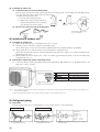
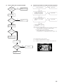
1. INVERTER WALL MOUNTED TYPE
ROOM AIR-CONDITIONER
Split system, Air to air
heat pump type
(
)
1.1 SRK20ZD-S SRK25ZC-S
SRK25ZD-S SRK35ZC-S
SRK35ZD-S SRK50ZC-S
SRK50ZD-S .............................................................. 2
1.2 SRK63ZE-S
SRK71ZE-S............................................................... 74
1
CONTENTS
1.1.1 GENERAL INFORMATION ....................................................................... 3
(1) Specific features .................................................................................... 3
(2) How to read the model name................................................................ 3
1.1.2 SELECTION DATA .................................................................................... 4
(1) Specifications ........................................................................................ 4
(2) Range of usage & limitations ............................................................... 11
(3) Exterior dimensions .............................................................................. 11
(4) Piping system ........................................................................................ 14
(5) Selection chart ....................................................................................... 15
1.1.3 ELECTRICAL DATA ................................................................................. 16
(1) Electrical wiring ..................................................................................... 16
1.1.4 OUTLINE OF OPERATION CONTROL BY MICROCOMPUTER ............ 18
(1) Operation control function by remote control switch ........................ 18
(2) Unit ON/OFF button ............................................................................... 19
(3) Power blackout auto restart function .................................................. 19
(4) Flap control ............................................................................................ 20
(5) Comfortable timer setting ..................................................................... 20
(6) Outline of heating operation ................................................................ 21
(7) Outline of cooling operation ................................................................ 23
(8) Outline of dehumidifying operation ..................................................... 24
(9) Outline of automatic operation ............................................................ 26
(10) Economical operation ........................................................................... 26
(11) Protective control function ................................................................... 26
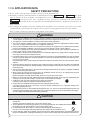
1.1.5 APPLICATION DATA ................................................................................ 32
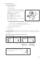
(1) Selection of location for installation.................................................... 33
(2) Installation of indoor unit ..................................................................... 34
(3) Installation of outdoor unit ................................................................... 36
(4) Refrigerant piping ................................................................................. 36
(5) Test run .................................................................................................. 38
(6) Precautions for wireless remote controller installation and
operation ................................................................................................ 39
1.1.6 MAINTENANCE DATA .............................................................................. 40
(1) Troubleshooting procedures for electrical equipment ...................... 40
(2) Servicing ................................................................................................ 58
1.1.7 REFRIGERANT PIPING INSTALLATION/SERVICING MANUAL
FOR AIR CONDITIONERS USING R410A .............................................. 59
(1) Outline .................................................................................................... 59
(2) Refrigerant piping installation ............................................................. 60
(3) Installation, removal and servicing...................................................... 66
(4) Refrigerant recovery ............................................................................. 71
2
1.1.1 GENERAL INFORMATION
(1) Specific features
The “Mitsubishi Daiya” room air-conditioner: SRK series are of split and wall mounted type and the unit consists of indoor unit and
outdoor unit with refrigerant precharged in factory. The indoor unit is composed of room air cooling or heating equipment with operation control switch and the outdoor unit is composed of condensing unit with compressor.
(a) Inverter (Frequency converter) for multi-steps power control
¡ Heating/Cooling
The rotational speed of a compressor is changed in step in relation to varying load, interlocked with the indoor and outdoor unit
fans controlled to change frequency, thus controlling the capacity.
¡ Allowing quick heating/cooling operation during start-up period. Constant room temperature by fine-tuned control after the
unit has stabilized.
(b) Fuzzy control
¡ Fuzzy control calculates the amount of variation in the difference between the return air temperature and the setting temperature
in compliance with the fuzzy rules in order to control the air capacity and the inverter frequency.
(c) Remote control flap
The flap can be automatically controlled by operating wireless remote control.
¡ Air scroll (AUTO): Flap operation is automatically control.
¡ Swing: This will swing the flap up and down.
¡ Memory flap: Once the flap position is set, the unit memorizes the position and continues to operate at the same position from
the next time.
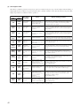
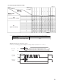
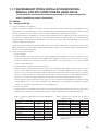
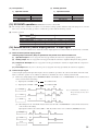
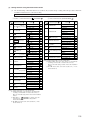
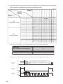
(d) Self diagnosis function
¡ We are constantly trying to do better service to our customers by installing such judges that show abnormality of operation as
follows.
RUN light
1 time flash
TIMER light
ON
2 time flash
6 time flash
Heat exchanger sensor error
Room temperature sensor error
RUN light
keeps flashing
Indoor fan motor error
RUN light
ON
RUN light
2 time flash
TIMER light
Outdoor (LED)
1 time flash
OFF
Outdoor temperature sensor error
2 time flash
OFF
Outdoor heat exchanger liquid
pipe sensor error
4 time flash
OFF
Discharge pipe sensor error
1 time flash
1 time flash
Current cut
2 time flash
2 time flash
Trouble of outdoor unit
3 time flash
3 time flash
Over current
5 time flash
5 time flash
Over heat of compressor
6 time flash
6 time flash
Error of signal transmission
7 time flash
(20, 25, 35 type only)
ON
Outdoor fan motor error
2 time flash
7 time flash
Rotor lock
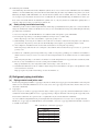
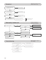
(2) How to read the model name
Example :
SR K 35
Z D-S
R410A models
Series No.
Inverter type
Product capacity
Wall mounted type
Split type room air-conditioner
3
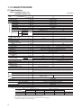
1.1.2 SELECTION DATA
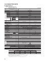
(1) Specifications
Model SRK20ZD-S (Indoor unit)
SRC20ZD-S (Outdoor unit)
(220/230/240V)
Model
SRK20ZD-S
Item
Refrigerant
piping
Operation data(1)
Cooling capacity(1)
Heating capacity(1)
Power source
Cooling input
Running current (Cooling)
Heating input
Running current (Heating)
Inrush current
COP
Sound level
Cooling
Power level
Noise level
Sound level
Heating
Power level
Exterior dimensions
Height × Width × Depth
Color
Net weight
Refrigerant equipment
Compressor type & Q’ty
Motor
Starting method
Heat exchanger
Refrigerant control
Refrigerant(3)
Refrigerant oil
Deice control
Air handling equipment
Fan type & Q’ty
Motor
(Cooling)
Air flow (at High)
(Heating)
Air filter, Q’ty
Shock & vibration absorber
Electric heater
Operation control
Operation switch
Room temperature control
Pilot lamp
Safety equipment
O.D
Connecting method
Attached length of piping
W
W
SRC20ZD-S
2000 (500~2800)
2700 (500~4600)
1 Phase, 220-240V, 50Hz
0.44 (0.1~0.91)
2.4/2.3/2.2
0.62 (0.09~1.27)
3.0/2.9/2.8
3.0/2.9/2.8
Cooling: 4.55 Heating: 4.35
Hi 36, Me 29, Lo 21
52
Hi 38, Me 32, Lo 25
54
kW
A
kW
A
A
dB
44
58
47
61
mm
250 × 815 × 249
540 × 720 × 290
kg
Cool white
9.0
Stucco white
32
–
RM-B5077MD1 (Rotary type) × 1
kW
–
0.75
–
Line starting
Louver fins & inner grooved tubing
Straight fins & inner grooved tubing
Capillary tubes + Electronic expansion valve
R410A 0.9 (Pre-Charged up to the piping length of 15m)
0.35 (MA68)
Microcomputer control
kg
R
W
CMM
Tangential fan × 1
Propeller fan × 1
29
7.2
8.3
Polypropylene net (washable) × 2
–
–
24
30
25
–
Cushion rubber (for compressor)
–
Wireless-Remote controller
–
Microcomputer thermostat
–
RUN (Green), TIMER (Yellow), HI POWER (Green), ECONO (Orange)
Compressor overheat protection, Heating overload protection (High pressure control), Overcurrent protection,
Frost protection, Serial signal error protection, Indoor fan motor error protection, Cooling overload protection
mm (in)
Insulation
Drain hose
Power source cord
Size × Core number
Connecting method
Accessories (included)
Optional parts
Connection wiring
Liquid line: φ6.35 (1/4″) Gas line: φ9.52 (3/8″)
Flare connecting
Liquid line: 0.47 m
–
Gas line : 0.40 m
Necessary (Both sides)
Connectable
2.5 m (3 cores with Earth)
1.5 mm2 × 4 cores (Including earth cable)
Terminal block (Screw fixing type)
Mounting kit
–
Notes (1) The data are measured at the following conditions.
Item
Operation
Cooling
Heating
Indoor air temperature
DB
WB
27ºC
19ºC
20ºC
–
Outdoor air temperature
DB
WB
35ºC
24ºC
7ºC
6ºC
The piping length is 7.5m.
(2) The operation data are applied to the 220/230/240V districts respectively.
(3) The refrigerant quantity to be charged includes the refrigerant in 15 m connecting piping.
(Purging is not required even for the short piping.)
4
Standards
ISO-T1, JIS C9612
ISO-T1, JIS C9612
Model SRK25ZD-S (Indoor unit)
SRC25ZD-S (Outdoor unit)
(220/230/240V)
Model
SRK25ZD-S
Item
Refrigerant
piping
Operation data(1)
Cooling capacity(1)
Heating capacity(1)
Power source
Cooling input
Running current (Cooling)
Heating input
Running current (Heating)
Inrush current
COP
Sound level
Cooling
Power level
Noise level
Sound level
Heating
Power level
Exterior dimensions
Height × Width × Depth
Color
Net weight
Refrigerant equipment
Compressor type & Q’ty
Motor
Starting method
Heat exchanger
Refrigerant control
Refrigerant(3)
Refrigerant oil
Deice control
Air handling equipment
Fan type & Q’ty
Motor
(Cooling)
Air flow (at High)
(Heating)
Air filter, Q’ty
Shock & vibration absorber
Electric heater
Operation control
Operation switch
Room temperature control
Pilot lamp
Safety equipment
O.D
Connecting method
Attached length of piping
W
W
SRC25ZD-S
2500 (500~3000)
3400 (500~4800)
1 Phase, 220-240V, 50Hz
0.62 (0.1~0.97)
3.1/3.0/2.9
0.94 (0.09~1.30)
4.5/4.3/4.1
4.5/4.3/4.1
Cooling: 4.03 Heating: 3.62
Hi 37, Me 30, Lo 22
53
Hi 39, Me 33, Lo 26
55
kW
A
kW
A
A
dB
44
58
47
61
mm
250 × 815 × 249
540 × 720 × 290
kg
Cool white
9.0
Stucco white
32
–
RM-B5077MD1 (Rotary type) × 1
kW
–
0.75
–
Line starting
Louver fins & inner grooved tubing
Straight fins & inner grooved tubing
Capillary tubes + Electronic expansion valve
R410A 0.9 (Pre-Charged up to the piping length of 15m)
0.35 (MA68)
Microcomputer control
kg
R
W
CMM
Tangential fan × 1
Propeller fan × 1
29
8.0
8.7
Polypropylene net (washable) × 2
–
–
24
30
25
–
Cushion rubber (for compressor)
–
Wireless-Remote controller
–
Microcomputer thermostat
–
RUN (Green), TIMER (Yellow), HI POWER (Green), ECONO (Orange)
Compressor overheat protection, Heating overload protection (High pressure control), Overcurrent protection,
Frost protection, Serial signal error protection, Indoor fan motor error protection, Cooling overload protection
mm (in)
Insulation
Drain hose
Power source cord
Size × Core number
Connecting method
Accessories (included)
Optional parts
Connection wiring
Liquid line: φ6.35 (1/4″) Gas line: φ9.52 (3/8″)
Flare connecting
Liquid line: 0.47 m
–
Gas line : 0.40 m
Necessary (Both sides)
Connectable
2.5 m (3 cores with Earth)
1.5 mm2 × 4 cores (Including earth cable)
Terminal block (Screw fixing type)
Mounting kit
–
Notes (1) The data are measured at the following conditions.
Item
Operation
Cooling
Heating
Indoor air temperature
DB
WB
27ºC
19ºC
20ºC
–
Outdoor air temperature
DB
WB
35ºC
24ºC
7ºC
6ºC
Standards
ISO-T1, JIS C9612
ISO-T1, JIS C9612
The piping length is 7.5m.
(2) The operation data are applied to the 220/230/240V districts respectively.
(3) The refrigerant quantity to be charged includes the refrigerant in 15 m connecting piping.
(Purging is not required even for the short piping.)
5
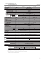
Model SRK35ZD-S (Indoor unit)
SRC35ZD-S (Outdoor unit)
(220/230/240V)
Model
SRK35ZD-S
Item
Refrigerant
piping
Operation data(1)
Cooling capacity(1)
Heating capacity(1)
Power source
Cooling input
Running current (Cooling)
Heating input
Running current (Heating)
Inrush current
COP
Sound level
Cooling
Power level
Noise level
Sound level
Heating
Power level
Exterior dimensions
Height × Width × Depth
Color
Net weight
Refrigerant equipment
Compressor type & Q’ty
Motor
Starting method
Heat exchanger
Refrigerant control
Refrigerant(3)
Refrigerant oil
Deice control
Air handling equipment
Fan type & Q’ty
Motor
(Cooling)
Air flow (at High)
(Heating)
Air filter, Q’ty
Shock & vibration absorber
Electric heater
Operation control
Operation switch
Room temperature control
Pilot lamp
Safety equipment
O.D
Connecting method
Attached length of piping
W
W
SRC35ZD-S
3500 (500~3900)
4500 (500~5100)
1 Phase, 220-240V, 50Hz
1.09 (0.1~1.22)
5.4/5.2/5.0
1.24 (0.09~1.32)
5.9/5.7/5.4
5.9/5.7/5.4
Cooling: 3.21 Heating: 3.63
Hi 41, Me 32, Lo 23
58
Hi 45, Me 36, Lo 27
59
kW
A
kW
A
A
dB
48
62
50
64
mm
250 × 815 × 249
540 × 720 × 290
kg
Cool white
9.0
Stucco white
35
–
RM-B5077MD1 [Rotary type] × 1
kW
–
0.90
–
Line starting
Louver fins & inner grooved tubing
Straight fins & inner grooved tubing
Capillary tubes + Electronic expansion valve
R410A 1.1 (Pre-Charged up to the piping length of 15m)
0.35 (MA68)
Microcomputer control
kg
R
W
CMM
Tangential fan × 1
Propeller fan × 1
29
8.9
10.3
Polypropylene net (washable) × 2
–
–
24
34
34
–
Cushion rubber (for compressor)
–
Wireless-Remote controller
–
Microcomputer thermostat
–
RUN (Green), TIMER (Yellow), HI POWER (Green), ECONO (Orange)
Compressor overheat protection, Heating overload protection (High pressure control), Overcurrent protection,
Frost protection, Serial signal error protection, Indoor fan motor error protection, Cooling overload protection
mm (in)
Insulation
Drain hose
Power source cord
Size × Core number
Connecting method
Accessories (included)
Optional parts
Connection wiring
Liquid line: φ6.35 (1/4″) Gas line: φ9.52 (3/8″)
Flare connecting
Liquid line: 0.47 m
–
Gas line : 0.40 m
Necessary (Both sides)
Connectable
2.5 m (3 cores with Earth)
1.5 mm2 × 4 cores (Including earth cable)
Terminal block (Screw fixing type)
Mounting kit
–
Notes (1) The data are measured at the following conditions.
Item
Operation
Cooling
Heating
Indoor air temperature
DB
WB
27ºC
19ºC
20ºC
–
Outdoor air temperature
DB
WB
35ºC
24ºC
7ºC
6ºC
The piping length is 7.5m.
(2) The operation data are applied to the 220/230/240V districts respectively.
(3) The refrigerant quantity to be charged includes the refrigerant in 15 m connecting piping.
(Purging is not required even for the short piping.)
6
Standards
ISO-T1, JIS C9612
ISO-T1, JIS C9612
Model SRK50ZD-S (Indoor unit)
SRC50ZD-S (Outdoor unit)
(220/230/240V)
Model
SRK50ZD-S
Item
Refrigerant
piping
Operation data(1)
Cooling capacity(1)
Heating capacity(1)
Power source
Cooling input
Running current (Cooling)
Heating input
Running current (Heating)
Inrush current
COP
Sound level
Cooling
Power level
Noise level
Sound level
Heating
Power level
Exterior dimensions
Height × Width × Depth
Color
Net weight
Refrigerant equipment
Compressor type & Q’ty
Motor
Starting method
Heat exchanger
Refrigerant control
Refrigerant(3)
Refrigerant oil
Deice control
Air handling equipment
Fan type & Q’ty
Motor
(Cooling)
Air flow (at High)
(Heating)
Air filter, Q’ty
Shock & vibration absorber
Electric heater
Operation control
Operation switch
Room temperature control
Pilot lamp
Safety equipment
O.D
Connecting method
Attached length of piping
W
W
SRC50ZD-S
5000 (600~5300)
6300 (600~7900)
1 Phase, 220-240V, 50Hz
1.66 (0.12~2.1)
7.6/7.3/7.0
1.96 (0.11~2.71)
9.0/8.6/8.2
9.0/8.6/8.2
Cooling: 3.01 Heating: 3.21
Hi 48, Me 42, Lo 26
61
Hi 46, Me 40, Lo 34
62
kW
A
kW
A
A
dB
48
61
49
64
mm
250 × 815 × 249
640 × 850 × 290
kg
Cool white
9.0
Stucco white
43
–
5CS102XFA [Scroll type] × 1
kW
kg
R
–
1.5
–
Line starting
Slit fins + Louver fins & inner grooved tubing
Straight fins & inner grooved tubing
Capillary tubes + Electronic expansion valve
R410A 1.35 (Pre-Charged up to the piping length of 15m)
0.36 (RB68A)
Microcomputer control
W
CMM
Tangential fan × 1
Propeller fan × 1
29
11.5
13.0
Polypropylene net (washable) × 2
–
–
45
42
42
–
Cushion rubber (for compressor)
–
Wireless-Remote controller
–
Microcomputer thermostat
–
RUN (Green), TIMER (Yellow), HI POWER (Green), ECONO (Orange)
Compressor overheat protection, Heating overload protection (High pressure control), Overcurrent protection,
Frost protection, Serial signal error protection, Indoor fan motor error protection, Cooling overload protection
mm (in)
Insulation
Drain hose
Power source cord
Size × Core number
Connecting method
Accessories (included)
Optional parts
Connection wiring
Liquid line: φ6.35 (1/4″) Gas line: φ12.7 (1/2″)
Flare connecting
Liquid line: 0.47 m
–
Gas line : 0.40 m
Necessary (Both sides)
Connectable
2.5 m (3 cores with Earth)
1.5 mm2 × 4 cores (Including earth cable)
Terminal block (Screw fixing type)
Mounting kit
–
Notes (1) The data are measured at the following conditions.
Item
Operation
Cooling
Heating
Indoor air temperature
DB
WB
27ºC
19ºC
20ºC
–
Outdoor air temperature
DB
WB
35ºC
24ºC
7ºC
6ºC
Standards
ISO-T1, JIS C9612
ISO-T1, JIS C9612
The piping length is 7.5m.
(2) The operation data are applied to the 220/230/240V districts respectively.
(3) The refrigerant quantity to be charged includes the refrigerant in 15 m connecting piping.
(Purging is not required even for the short piping.)
If the piping length is longer, when it is 15 to 25m, add 20 g refrigerant per meter.
7
Model SRK25ZC-S (Indoor unit)
SRC25ZC-S (Outdoor unit)
(220/230/240V)
Model
SRK25ZC-S
Item
Refrigerant
piping
Operation data(1)
Cooling capacity(1)
Heating capacity(1)
Power source
Cooling input
Running current (Cooling)
Heating input
Running current (Heating)
Inrush current
COP
Sound level
Cooling
Power level
Noise level
Sound level
Heating
Power level
Exterior dimensions
Height × Width × Depth
Color
Net weight
Refrigerant equipment
Compressor type & Q’ty
Motor
Starting method
Heat exchanger
Refrigerant control
Refrigerant(3)
Refrigerant oil
Deice control
Air handling equipment
Fan type & Q’ty
Motor
(Cooling)
Air flow (at High)
(Heating)
Air filter, Q’ty
Shock & vibration absorber
Electric heater
Operation control
Operation switch
Room temperature control
Pilot lamp
Safety equipment
O.D
Connecting method
Attached length of piping
W
W
SRC25ZC-S
2500 (500~3000)
3400 (500~4800)
1 Phase, 220-240V, 50Hz
0.62 (0.1~0.97)
3.1/3.0/2.9
0.94 (0.09~1.30)
4.5/4.3/4.1
4.5/4.3/4.1
Cooling: 4.03 Heating: 3.62
Hi 37, Me 30, Lo 22
53
Hi 39, Me 33, Lo 26
55
kW
A
kW
A
A
dB
44
58
47
61
mm
250 × 815 × 247
540 × 720 × 290
kg
Cool white
9.0
Stucco white
32
–
RM-B5077MD1 (Rotary type) × 1
kW
–
0.75
–
Line starting
Louver fins & inner grooved tubing
Straight fins & inner grooved tubing
Capillary tubes + Electronic expansion valve
R410A 0.9 (Pre-Charged up to the piping length of 15m)
0.35 (MA68)
Microcomputer control
kg
R
W
CMM
Tangential fan × 1
Propeller fan × 1
29
8.0
8.7
Polypropylene net (washable) × 2
–
–
24
30
25
–
Cushion rubber (for compressor)
–
Wireless-Remote controller
–
Microcomputer thermostat
–
RUN (Green), TIMER (Yellow), HI POWER (Green), ECONO (Orange)
Compressor overheat protection, Heating overload protection (High pressure control), Overcurrent protection,
Frost protection, Serial signal error protection, Indoor fan motor error protection, Cooling overload protection
mm (in)
Insulation
Drain hose
Power source cord
Size × Core number
Connecting method
Accessories (included)
Optional parts
Connection wiring
Liquid line: φ6.35 (1/4″) Gas line: φ9.52 (3/8″)
Flare connecting
Liquid line: 0.47 m
–
Gas line : 0.40 m
Necessary (Both sides)
Connectable
2.5 m (3 cores with Earth)
1.5 mm2 × 4 cores (Including earth cable)
Terminal block (Screw fixing type)
Mounting kit
–
Notes (1) The data are measured at the following conditions.
Item
Operation
Cooling
Heating
Indoor air temperature
DB
WB
27ºC
19ºC
20ºC
–
Outdoor air temperature
DB
WB
35ºC
24ºC
7ºC
6ºC
The piping length is 7.5m.
(2) The operation data are applied to the 220/230/240V districts respectively.
(3) The refrigerant quantity to be charged includes the refrigerant in 15 m connecting piping.
(Purging is not required even for the short piping.)
8
Standards
ISO-T1, JIS C9612
ISO-T1, JIS C9612
Model SRK35ZC-S (Indoor unit)
SRC35ZC-S (Outdoor unit)
(220/230/240V)
Model
SRK35ZC-S
Item
Refrigerant
piping
Operation data(1)
Cooling capacity(1)
Heating capacity(1)
Power source
Cooling input
Running current (Cooling)
Heating input
Running current (Heating)
Inrush current
COP
Sound level
Cooling
Power level
Noise level
Sound level
Heating
Power level
Exterior dimensions
Height × Width × Depth
Color
Net weight
Refrigerant equipment
Compressor type & Q’ty
Motor
Starting method
Heat exchanger
Refrigerant control
Refrigerant(3)
Refrigerant oil
Deice control
Air handling equipment
Fan type & Q’ty
Motor
(Cooling)
Air flow (at High)
(Heating)
Air filter, Q’ty
Shock & vibration absorber
Electric heater
Operation control
Operation switch
Room temperature control
Pilot lamp
Safety equipment
O.D
Connecting method
Attached length of piping
W
W
SRC35ZC-S
3500 (500~3900)
4500 (500~5100)
1 Phase, 220-240V, 50Hz
1.09 (0.1~1.22)
5.4/5.2/5.0
1.24 (0.09~1.32)
5.9/5.7/5.4
5.9/5.7/5.4
Cooling: 3.21 Heating: 3.63
Hi 41, Me 32, Lo 23
58
Hi 45, Me 36, Lo 27
59
kW
A
kW
A
A
dB
48
62
50
64
mm
250 × 815 × 247
540 × 720 × 290
kg
Cool white
9.0
Stucco white
35
–
RM-B5077MD1 [Rotary type] × 1
kW
–
0.90
–
Line starting
Louver fins & inner grooved tubing
Straight fins & inner grooved tubing
Capillary tubes + Electronic expansion valve
R410A 1.1 (Pre-Charged up to the piping length of 15m)
0.35 (MA68)
Microcomputer control
kg
R
W
CMM
Tangential fan × 1
Propeller fan × 1
29
8.9
10.3
Polypropylene net (washable) × 2
–
–
24
34
34
–
Cushion rubber (for compressor)
–
Wireless-Remote controller
–
Microcomputer thermostat
–
RUN (Green), TIMER (Yellow), HI POWER (Green), ECONO (Orange)
Compressor overheat protection, Heating overload protection (High pressure control), Overcurrent protection,
Frost protection, Serial signal error protection, Indoor fan motor error protection, Cooling overload protection
mm (in)
Insulation
Drain hose
Power source cord
Size × Core number
Connecting method
Accessories (included)
Optional parts
Connection wiring
Liquid line: φ6.35 (1/4″) Gas line: φ9.52 (3/8″)
Flare connecting
Liquid line: 0.47 m
–
Gas line : 0.40 m
Necessary (Both sides)
Connectable
2.5 m (3 cores with Earth)
1.5 mm2 × 4 cores (Including earth cable)
Terminal block (Screw fixing type)
Mounting kit
–
Notes (1) The data are measured at the following conditions.
Item
Operation
Cooling
Heating
Indoor air temperature
DB
WB
27ºC
19ºC
20ºC
–
Outdoor air temperature
DB
WB
35ºC
24ºC
7ºC
6ºC
Standards
ISO-T1, JIS C9612
ISO-T1, JIS C9612
The piping length is 7.5m.
(2) The operation data are applied to the 220/230/240V districts respectively.
(3) The refrigerant quantity to be charged includes the refrigerant in 15 m connecting piping.
(Purging is not required even for the short piping.)
9
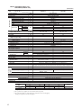
Model SRK50ZC-S (Indoor unit)
SRC50ZC-S (Outdoor unit)
(220/230/240V)
Model
SRK50ZC-S
Item
Refrigerant
piping
Operation data(1)
Cooling capacity(1)
Heating capacity(1)
Power source
Cooling input
Running current (Cooling)
Heating input
Running current (Heating)
Inrush current
COP
Sound level
Cooling
Power level
Noise level
Sound level
Heating
Power level
Exterior dimensions
Height × Width × Depth
Color
Net weight
Refrigerant equipment
Compressor type & Q’ty
Motor
Starting method
Heat exchanger
Refrigerant control
Refrigerant(3)
Refrigerant oil
Deice control
Air handling equipment
Fan type & Q’ty
Motor
(Cooling)
Air flow (at High)
(Heating)
Air filter, Q’ty
Shock & vibration absorber
Electric heater
Operation control
Operation switch
Room temperature control
Pilot lamp
Safety equipment
O.D
Connecting method
Attached length of piping
W
W
SRC50ZC-S
5000 (600~5300)
6300 (600~7900)
1 Phase, 220-240V, 50Hz
1.66 (0.12~2.1)
7.6/7.3/7.0
1.96 (0.11~2.71)
9.0/8.6/8.2
9.0/8.6/8.2
Cooling: 3.01 Heating: 3.21
Hi 48, Me 42, Lo 26
61
Hi 46, Me 40, Lo 34
62
kW
A
kW
A
A
dB
48
61
49
64
mm
250 × 815 × 247
640 × 850 × 290
kg
Cool white
9.0
Stucco white
43
–
5CS102XFA [Scroll type] × 1
kW
kg
R
–
1.5
–
Line starting
Slit fins + Louver fins & inner grooved tubing
Straight fins & inner grooved tubing
Capillary tubes + Electronic expansion valve
R410A 1.35 (Pre-Charged up to the piping length of 15m)
0.36 (RB68A)
Microcomputer control
W
CMM
Tangential fan × 1
Propeller fan × 1
29
11.5
13.0
Polypropylene net (washable) × 2
–
–
45
42
42
–
Cushion rubber (for compressor)
–
Wireless-Remote controller
–
Microcomputer thermostat
–
RUN (Green), TIMER (Yellow), HI POWER (Green), ECONO (Orange)
Compressor overheat protection, Heating overload protection (High pressure control), Overcurrent protection,
Frost protection, Serial signal error protection, Indoor fan motor error protection, Cooling overload protection
mm (in)
Insulation
Drain hose
Power source cord
Size × Core number
Connecting method
Accessories (included)
Optional parts
Connection wiring
Liquid line: φ6.35 (1/4″) Gas line: φ12.7 (1/2″)
Flare connecting
Liquid line: 0.47 m
–
Gas line : 0.40 m
Necessary (Both sides)
Connectable
2.5 m (3 cores with Earth)
1.5 mm2 × 4 cores (Including earth cable)
Terminal block (Screw fixing type)
Mounting kit
–
Notes (1) The data are measured at the following conditions.
Item
Operation
Cooling
Heating
Indoor air temperature
DB
WB
27ºC
19ºC
20ºC
–
Outdoor air temperature
DB
WB
35ºC
24ºC
7ºC
6ºC
The piping length is 7.5m.
(2) The operation data are applied to the 220/230/240V districts respectively.
(3) The refrigerant quantity to be charged includes the refrigerant in 15 m connecting piping.
(Purging is not required even for the short piping.)
If the piping length is longer, when it is 15 to 25m, add 20 g refrigerant per meter.
10
Standards
ISO-T1, JIS C9612
ISO-T1, JIS C9612
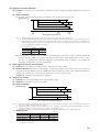
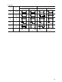
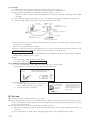
(2) Range of usage & limitations
Models
SRK20ZD-S, 25ZD-S, 35ZD-S
SRK25ZC-S, 35ZC-S
Item
Indoor return air temperature
(Upper, lower limits)
SRK50ZD-S
SRK50ZC-S
Refer to the selection chart
Outdoor air temperature
(Upper, lower limits)
Refrigerant line (one way) length
Vertical height difference between
outdoor unit and indoor unit
Max. 15m
Max. 25m
Max. 10m (Outdoor unit is higher)
Max. 10m (Outdoor unit is lower)
Max. 15m (Outdoor unit is higher)
Max. 15m (Outdoor unit is lower)
Rating ± 10%
Power source voltage
Voltage at starting
Min. 85% of rating
Frequency of ON-OFF cycle
Max. 10 times/h
ON and OFF interval
Max. 3 minutes
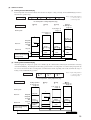
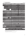
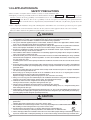
(3) Exterior dimensions
(a) Indoor unit
Models SRK20ZD-S, 25ZD-S, 35ZD-S, 50ZD-S
Unit: mm
A
815
249
3
9
250
60
Piping hole right(left)
Terminal block
580
450
216.5
45
148.5
450
216.5
8.2
47.2
148.5
42.7
117.5
150
117.5
236.1
44.5
175
56
18
Remote controller
)
14.5
45
(
60
60
45
Piping for Gas 67.5
20,25,35: ø9.52
50: ø12.7 397.1
53.5
5.7
44.5
788
5
Piping for Liquid 465.1 (ø6.35)
Drain hose 540 (ø16)
Piping hole (ø65)
Piping hole (ø65)
VIEW A
11
Models SRK25ZC-S, 35ZC-S, 50ZC-S
Unit: mm
A
815
3
247
Therminal block
150
9
250
60
Piping hole right (left)
4.5
117.5
580
450
216.5
148.5
450
56
216.5
47.2
148.5
18
Remote controller
8.2
42.7
117.5
(
60
60
)
Piping for Liquid 465.1 (ø6.35)
Drain hose 540 (ø16)
VIEW A
Piping hole (ø65)
12
Piping hole (ø65)
14.5
4.5
4.5
236.1
44.5
44.5
Piping for Gas 67.5
25,35: ø9.52
50: ø12.7 397.1
53.5
5.7
175
788
5
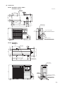
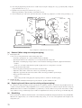
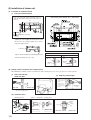
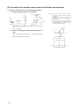
(b) Outdoor unit
Models SRC20ZD-S, 25ZD-S, 35ZD-S
SRC25ZC-S, 35ZC-S
Unit: mm
Drain holes
50
264.5
404.5
17.8
510
71
340
14
47.4
290
312.5
42.6
13.5
12
139
2-16 x12
720
Terminal block
61.9
39.7
°
99.9
°
40
40
14.4
Service valve (Liquid)
Flare connection ø6.35 (1/4")
33.3
540
139.3
Service valve (Gas)
Flare connecting ø9.52 (3/8")
Models SRC50ZD-S
SRC50ZC-S
50
14
49.6
314
290
43.5
12
476
203.1
328
Drain holes
12
286.4
510
850
136.9
Elogated hole
(2-12 x16)
Terminal block
640
124
34.6
Service valve (Liquid)
ø6.35 (1/4'')
Service valve (Gas)
ø12.7 (1/2'')
15
20˚
20˚
100.3
42.7
Ground
terminal
13
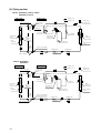
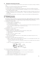
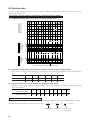
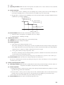
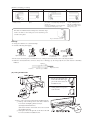
(4) Piping system
Models SRK20ZD-S, 25ZD-S, 35ZD-S
SRK25ZC-S, 35ZC-S
Indoor unit
Outdoor unit
Cooling cycle
Heating cycle
Flare connection
Piping
(Gas)
ø9.52
Service valve
(Gas)
Outdoor air
temp. sensor
Check joint
4 way valve
Accumulator
Room temp.
sensor
Discharge pipe
temp. sensor
Heat
exchanger
sensor
Heat
exchanger
Heat
exchanger
Compressor
Piping
(Liquid)
ø6.35
Heat exchanger
sensor
Service valve (Liquid)
Capillary tube
Electronic
expansion valve
Strainer
Flare connetion
Capillary tube
Models SRK50ZD-S
SRK50ZC-S
Indoor unit
Outdoor unit
Cooling cycle
Heating cycle
Flare connection
Piping
(Gas)
ø12.7
Service valve
(Gas)
Outdoor air
temp. sensor
Muffler
Check joint
4 way valve
Strainer
Room temp.
sensor
Heat
exchanger
sensor
Heat
exchanger
Discharge pipe
temp. sensor
Heat
exchanger
Compressor
Piping
(Liquid)
ø6.35
Service valve (Liquid)
Capillary tube
Flare connection
14
Strainer
Electronic
expansion valve
Capillary tube
Heat exchanger
sensor
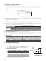
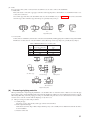
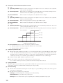
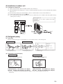
(5) Selection chart
Correct the cooling and heating capacity in accordance with the conditions as follows. The net cooling and heating capacity can be
obtained in the following way.
Net capacity = Capacity shown on specification ✕ Correction factors as follows.
(a) Coefficient of cooling and heating capacity in relation to temperatures
Coefficient of cooling &
Heating capacity in
relation to temperature
1.3
1.2
Cooling
1.1
1.0
Heating
0.9
0.8
0.7
0.6
Outdoor air D.B.
temperature
°C D.B.
Cooling operation
Applicable range
43
40
35
30
25
20
15
24
14
16
18
20
22
Indoor air D.B.
temperature
°C D.B.
Heating operation
Indoor air W.B. temperature °C W.B. ISO-T1 Standard Condition
27
25
20
15
10
20
-10
-5
0
5
10
15
Outdoor air W.B. temperature °C W.B. ISO-T1 Standard Condition
(b) Correction of cooling and heating capacity in relation to one way length of refrigerant piping
It is necessary to correct the cooling and heating capacity in relation to the one way piping length between the indoor and outdoor
units.
Piping length [m]
7
10
15
20
25
Cooling
1.0
0.99
0.975
0.965
0.95
Heating
1.0
1.0
1.0
1.0
1.0
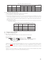
(c) Correction relative to frosting on outdoor heat exchanger during heating
In additions to the foregoing corrections (1), (2) the heating capacity needs to be adjusted also with respect to the frosting on the
outdoor heat exchanger.
Air inlet temperature of
outdoor unit in ˚CWB
-10
-9
-7
-5
-3
-1
1
3
5
Adjustment coefficient
0.95
0.94
0.93
0.91
0.88
0.86
0.87
0.92
1.00
How to obtain the cooling and heating capacity
Example : The net cooling capacity of the model SRK35ZD-S with the piping length of 15m, indoor wet-bulb temperature at 19.0˚C
and outdoor dry-bulb temperature 35˚C is Net cooling capacity =
3500
✕
SRK35ZD-S
0.975
✕
Length 15m
1.0
=
3413 W
Factor by air
temperatures
15
16
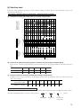
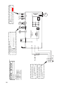
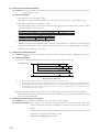
CM
F
FMI
FMo
SM
RE
Compressor motor
Fuse
Fan motor (Indoor)
Fan motor (Outdoor)
Flap motor
F
Reactor
Parts name
Meaning of marks
Symbol
RD
BK
WH
Y
BL
CNM
1
3
4
5
6
CNU
52C4
Th1
Th2
Th4
Th5
Th6
ZNR
Symbol
Color symbol
BK
Black
BR
Brown
RD
Red
Blue
BL
WH
White
Y/GN Yellow/Green
SM
FMI
HEAT
EXCHANGER
Y/GN
BL
BR
Power source
1 Phase
220/230/240V 50Hz
52C
J
Th1
Th2
CNG
20S
52C
DS
EEV
Symbol
Parts name
TB
4 way valve (coil)
Magnetic contactor
Diode stack
Electronic expansion valve
Printed circuit board
ZNR
Parts name
)
N
Room temp. sensor
Heat exchanger sensor (Indoor unit)
Heat exchanger sensor (Outdoor unit)
Outdoor air temp. sensor
Discharge pipe temp. sensor
Varistor
Wireless
R-Amp
Display
CNE
(
52C3
F1
250V
3.15A
52C
1
WH 2
RD
3
BK
Indoor unit
TB
3
2
1
CM
Y/GN
RD
WH
BK
RD
WH
BK
Outdoor unit
U
V
W
N
S.IN
Power
transistor
DS
C2
G
P
CND
CNA
CNE
CNB
Printed circuit
board
R.IN
F2 (250V 20A)
Re
Th6
Th5
Th4
FMo
EEV
20S
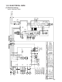
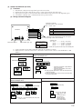
1.1.3 ELECTRICAL DATA
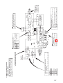
(1) Electrical wiring
Models SRK20ZD-S, 25ZD-S, 35ZD-S
SRK25ZC-S, 35ZC-S
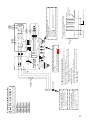
CFo
CM
F
FMI
FMo
SM
RL
Symbol
RD
BK
WH
Y
BL
Capacitor for FMo
Compressor motor
Fuse
Fan motor (Indoor)
Fan motor (Outdoor)
Flap motor
F
Inspection lamp
Parts name
Meaning of marks
Color symbol
BK
Black
BR
Brown
RD
Red
Green
GR
Blue
BL
Orange
OR
White
WH
Y/GN Yellow/Green
SM
FMI
HEAT
EXCHANGER
Y/GN
52C4
52C
52C3
N
52C
J
L
Th1
Th2
Th3
Th4
Th5
Th6
Symbol
CNM
1
3
4
5
6
CNU
Th1
Th2
CNG
ZNR
20S
52C
DS
EEV
Symbol
Parts name
TB
Varistor
4 way valve (coil)
Magnetic contactor
Diode stack
Electronic expansion valve
Th3
CNF
Printed circuit board
ZNR
Parts name
)
Inductor
Room temp. sensor
Heat exchanger sensor (Indoor unit)
Humidity sensor
Heat exchanger sensor (Outdoor unit)
Outdoor air temp. sensor
Discharge pipe temp. sensor
Wireless
R-Amp
Display
CNE
(
F1
250V
3.15A
WH 2
RD
3
BL
1
BK
Indoor unit
BR
Power source
1 Phase
220/230/240V 50Hz
TB
3
2
1
FMo
Y/GN
RD
WH
BK
CFo
EEV
Th6
Th5
Th4
20S
Y
Outdoor unit
OR
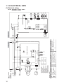
PWB3
P_1
RD P_1
DS
P2
U
P
N
V
Power
transistor W
N2
WH
BK
RD
AF_L2 OR
AF_L1 OR
AC.N AC.L
GR BL
N-OUT2 L-OUT2
GR BL
N1 L
IC12
CNH
PWB2
CNG
BK N_3
RL
PWB1
N_1
DC-P
RD
CNH
1 CNG 2
DC-N
BK
CNJ
CNN
SWITCHING
POWER
CIRCUIT
CND
CNB
CNS
G3 CNO.1 N-1 L-1
F2 (250V 15A)
L
CM
Models SRK50ZD-S
SRK50ZC-S
17
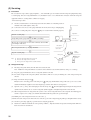
1.1.4 OUTLINE OF OPERATION CONTROL BY MICROCOMPUTER
(1) Operation control function by remote control switch
Remote controller
Models All models
S Operation section
FAN SPEED button
OPERATION MODE select button
Each time the button is pushed, the
indicator is switched over in turn.
Each time the button is pushed, the
indicator is switched over in turn.
HI POWER
ECONO
AUTO
HI
MED
LO
HI POWER button
This button changes the HI POWER mode.
AM
PM
ON
FAN SPEED
ON/OFF button
Press for starting operation, press again for
stopping.
OFF
ON OFF
MODE
ECONOMY button
This button changes the ECONOMY mode.
AIR FLOW button
HI POWER TEMP
This button changes the flap mode. When
pressed, this button changes the mode in the
following order:
AIR FLOW
TIME
(Air scroll)
ECONO
TEMPERATURE button
CANCEL
This button sets the room temperature.
(This button changes the present time and
TIMER time.)
(Swing)
ON
(Flap stopped)
TIME
OFF
TIMER
RESERVE
ACL
CANCEL button
ON TIMER button
This button cancels the ON timer and OFF
timer.
This button selects ON TIMER operation.
RESERVE button
This button sets the present time and
TIMER time.
Clock switch
This switch for setting the clock.
RESET switch
Switch for resetting microcomputer.
OFF TIMER button
This button selects OFF TIMER operation.
• The above illustration shows all controls, but in practice
only the relevant parts are shown.
S Indication section
ECONOMY MODE indicator
HI POWER MODE indicator
Indicates during economy mode operation.
Indicates during Hi power mode operation.
HI POWER
TEMPERATURE indicator
Indicates set temperature.
(Does not indicate temperature when operation
mode is on AUTO)
AUTO
HI
MED
LO
ECONO
AM
PM
OPERATION MODE indicator
Indicates selected operation with
[
ON
OFF
(Auto) •
(Cool) •
lamp.
(Heat) •
(Dry)]
Clock indicator
Indicates present time or timer setting time.
FAN SPEED indicator
Indicates set air flow rate with
lamp.
OFF TIMER indicator
Indicates OFF TIMER operation.
AIR FLOW indicator
Shows selected flap mode.
ON TIMER indicator
Indicates during ON TIMER operation.
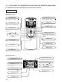
18
Unit indication section
Models SRK20ZD-S, 25ZD-S, 35ZD-S, 50ZD-S
Models SRK25ZC-S, 35ZC-S, 50ZC-S
RUN (HOT KEEP) light (green)
• Illuminates during operation.
• Flashes at air flow stop due to the ‘HOT KEEP’.
RUN
TIMER light (yellow)
Illuminates during TIMER operation.
TIMER
HI POWER light (green)
HIPOWER
Illuminates during HI POWER operation.
ECONO
ECONOMY light (orange)
Illuminates during ECONOMY operation.
(2) Unit ON/OFF button
When the remote controller batteries become weak, or if the remote controller is lost or malfunctioning, this button may be used to turn
the unit on and off.
(a) Operation
Push the button once to place the unit in the automatic mode. Push it once more to turn the unit off.
(b) Details of operation
The unit will go into the automatic mode in which it automatically determines, from room temperature (as detected by sensor),
whether to go into the cooling, thermal dry or heating modes.
Function
Operation mode
Room temperature
setting
Cooling
About 25ºC
Thermal dry
About 25ºC
Heating
About 26ºC
Fan speed
Flap
Timer switch
Auto
Auto
Continuous
Models SRK20ZD-S, 25ZD-S, 35ZD-S, 50ZD-S
Models SRK25ZC-S, 35ZC-S, 50ZC-S
Unit ON/OFF button
Unit ON/OFF button
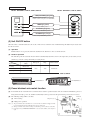
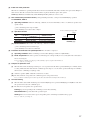
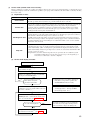
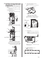
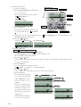
(3) Power blackout auto restart function
(a)
Power blackout auto restart function is a function that records the operational status of the air-conditioner immediately prior to it
being switched off by a power cut, and then automatically resumes operations at that point after the power has been restored.
(b) The following settings will be cancelled:
(i)
Timer settings
Jumper wire (J7)
(ii) High-power operations
Notes (1) The power blackout auto restart function is set at on when the air-conditioner is shipped from the
factory. Consult with your dealer if this function needs to be switched off.
(2) When power failure ocurrs, the timer setting is cancelled. Once power is resumed, reset the timer.
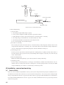
(3) If the jumper wire (J7) “REMOTE/AUTORESTART” is cut, auto restart is disabled. (See the diagram at
right)
19
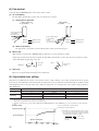
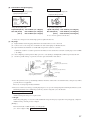
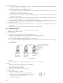
(4) Flap control
Control the flap by AIRFLOW button on the wireless remote control.
(a) Air scroll (AUTO)
The flap will be automatically set to the angle of air flow best to operation.
(i)
Starting time of operation
During cooling and
s dry operation
t
During heating
s operation
t
Stops for approximately
5 seconds in the
horizontal position.
Thick line
: Rapid movement
Thin line
: Slow movement
Stops for approximately
5 seconds in this
position.
Thick line
: Rapid movement
Thin line
: Slow movement
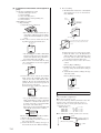
(ii) When not operating
The flap returns to the position of air flow directly below, when operation has stopped.
(b) Memory flap
While the flap is operating if the AIRFLOW button is pushed once, it stops swinging at an angle.
As this angle is memorized in the microcomputer, the flap will be automatically set to the angle when next operation is started.
¡ Recommendable stopping angle of the flap
HEAT
Horizontal
blowing
COOL•DRY
Slant forward
blowing
(c) Swing flap
Flap moves in upward and downward directions continuously.
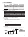
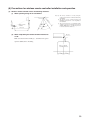
(5) Comfortable timer setting
If the timer is set at ON when the operation select switch is set at the cooling or heating, or the cooling or heating in auto mode operation
is selected, the comfortable timer starts and determines the starting time of next operation based on the initial value of 15 minutes and the
relationship between the room temperature at the setting time (temperature of room temperature sensor) and the setting temperature.
(Max. 60 minutes)
Operation mode
At cooling
At heating
3 < Room temp. – Setting temp.
Operation start time correction value (Min.)
1 < Room temp. – Setting temp. <
=3
+5
No change
–5
3 < Setting temp. – Room temp.
2 < Setting temp. – Room temp. <
=3
Setting temp. – Room temp. <
=2
+5
No change
–5
Room temp. – Setting temp. <
=1
Notes (1) At 5 minutes before the timer ON time, operation starts regardless of the temperature of the room temperature sensor (Th1).
(2) This function does not operate when in the Dry or Auto Dry mode.
However, the operation in item (1) does operate in the Auto Dry mode.
(3) During the comfortable timer operation, both the RUN light and TIMER light illuminate and the TIMER light goes off after expiration of the timer, ON setting
time.
(Example) Heating
Corrects the starting time of next operation by
calculating the temperature difference.
Setting temperature
¡ If the difference (= Setting temperature – Room temperature) is 4ºC, the correction value is found to be +5 minutes from the table shown above so that the starting time
of next operation is determined as follows:
15 min. earlier + 5 min. = 20 min. earlier
↑
↑
Current operation
Correction value
start time
Room temperature
Operation starting time
Time
20
15 min.
earlier
10 min.
earlier
5 min.
earlier
Setting time
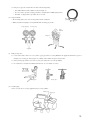
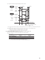
(6) Outline of heating operation
(a)
Operation of major functional components in heating mode
Item
When the inverter
speed is 0rps
Functional
components
When the inverter speed
is other than 0rps
When the inverter speed is 0rps
due to an anomalous stop
Indoor fan motor
ON
ON
OFF
Flaps
ON or OFF
ON or OFF
Stop position control
Display
Lights up
Lights up
Lights up or flashes
52C
ON
ON
OFF after stop mode
Outdoor fan motor
OFF (20, 25, 35 type)
Depending on the stop mode (50 type)
ON
OFF (20, 25, 35 type)
Depending on the stop mode (50 type)
4-way valve
Electronic expansion valve
ON
Depending on the stop mode
Depending on the stop mode
Depending on the EEV control
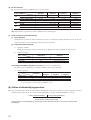
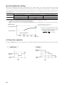
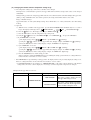
(b) Air flow selection
(i) Speed of inverter changes within the range of selected air flow.
Model
SRK20ZD-S
Air flow selection
Inverter command speed
Auto
SRK50ZC-S
30~102rps
30~100rps
Air flow
15~120rps
30~102rps
15~120rps
8th speed fixed
Inverter command speed
30~72rps
Air flow
6th/7th speed
30~72rps
30~76rps
15~62rps
6th speed fixed
Inverter command speed
LO
SRK50ZD-S
SRK35ZC-S
Depends on inverter command speed.
Inverter command speed
MED
SRK35ZD-S
SRK25ZC-S
30~100rps
Air flow
HI
SRK25ZD-S
30~42rps
Air flow
4th/5th speed
30~42rps
30~46rps
4th speed fixed
15~38rps
3rd speed fixed
(ii) When the defrosting, protection device, etc. is actuated, operation is performed in the corresponding mode.
(iii) Outdoor unit blower operates in accordance with the inverter command speed.
(c)
Details of control at each operation mode (pattern)
(i) Fuzzy operation
Deviation between the room temperature setting correction temperature and the suction air temperature is calculated in
accordance with the fuzzy rule, and used for control of the air capacity and the inverter speed.
(ii) Heating thermostat operation
¡ Operating conditions
If the speed obtained with the fuzzy calculation drops below -24 rps during the heating fuzzy operation, the operation
changes to the heating thermostat operation.
¡ Detail of operation
Model
Item
Inverter speed
SRK20ZD-S, 25ZD-S, 35ZD-S
SRK50ZD-S
SRK25ZC-S, 35ZC-S
SRK50ZC-S
0rps [Comp. stopped]
10 rps [10sec.] → 0rps [Comp. stopped]
Hot keep normal mode → 1st speed
Indoor fan
Outdoor fan
2nd speed [1min.] → stop
Stop
Flap
Horizontal
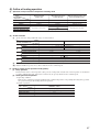
(c) Hot keep operation
If the hot keep operation is selected during the heating operation, the indoor blower is controlled based on the temperature of
the indoor unit heat exchanger (detected with Th2, indoor unit heat exchanger sensor) to prevent blowing of cool wind.
¡ Normal mode (Normal heating operation, operation after HI POWER completion)
(20, 25, 35 only)
8th speed
(20, 25, 35 only)
9th speed
¡ Values of A, B
7th speed
Indoor fan
6th speed
At 0 rps command
Other than 0 rps
command
5th speed
4th speed
A
B
22
25
17
19
3rd speed
1st speed
OFF
A
B 20~35: 23°C 28 29.5
31.5
34
36
50: 20°C
Indoor heat exchanger temp. (˚C)
37.5
39
40
Note (1) Refer to the table shown above right for the values A and B.
21
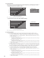
¡ Hot keep M mode [During HI POWER operation (for 15 min.)]
(20, 25, 35 type only)
(20, 25, 35 type only) 9th speed
8th speed
¡ Values of A, B
7th speed
Indoor fan
6th speed
5th speed
At 0 rps command
Other than 0 rps
command
4th speed
3rd speed
A
B
22
25
17
19
1st speed
OFF
A
B
29
31
32
34
36
43
(40)
(43)
(47)
Indoor heat exchanger temp. (˚C)
Notes (1) Refer to the table shown above right for the values A and B.
Note (2) Values in (
) are for type 20, 25, 35.
(iv) Defrosting operation
1)
Starting conditions (Defrosting operation can be started only when all of the following conditions are met.)
1 After start of heating operation → When it elapsed 35 minutes. (Accumulated operation time)
2 After end of defrosting operation → When it elapsed 35 minutes. (Accumulated compressor operation time)
3 Outdoor unit heat exchanger sensor (Th4) temperature → When the temperature has been below –5ºC for 3 minutes
continuously.
4 When the temperature difference between the outdoor air sensor temperature and the outdoor unit heat exchanger
sensor temperature exceeded 20. 25 type: 7.0°C, 35 type: 5.0°C, 50 type: 4.0°C
5 During continuous compressor operation
In addition, when the speed command from the indoor controller of the indoor unit during heating operation has
counted 0 rps 10 times or more and all conditions of 1, 2 and 3 above are satisfied (note that when the temperature
for Th4 is -5°C or less: 62 rps or more, -4°C or less: less than 62 rps), defrost operation is started.
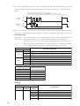
2)
Operation of functional components during defrosting operation
¡ 20, 25, 35 type
Indoor unit
Indoor fan
Corresponding
to speed
Hot keep
OFF
RUN light
Outdoor unit
Inverter
command
ON
Flashing
(Hot keep)
Hot keep
Fuzzy calculated
value
0
70 rps
(1)
6th speed
Outdoor fan
4-way valve
6th speed
Corresponding
to speed
OFF
ON
OFF
60 sec.
Defrost operation 50 sec.
preparation
Defrost operation
Final defrost operation
Normal heating operation restored
Defrost end
(Th4 ≥ 13˚C, 10 minutes)
Defrost control
Note (1) When outdoor unit heat exchanger sensor (Th4) temperature becomes 2°C or higher, inverter command changes 70 rps to 50
rps.
22
¡ 50 type
Indoor unit
Hot keep
Corresponding
to speed
Indoor fan
OFF
ON
Flashing
(Hot keep)
RUN light
Outdoor unit
Inverter
command
Hot keep
Fuzzy calculated
value
0
70 rps
(1)
2nd speed
Outdoor fan
2nd speed
Corresponding
to speed
OFF
ON
OFF
4-way valve
75 sec.
Defrost operation 60 sec.
preparation
Defrost operation
Final defrost operation
Normal heating operation restored
Defrost end
(Th4≥20°C, 10 minutes)
Defrost control
Note (1) When outdoor unit heat exchanger sensor (Th4) temperature becomes 7°C or higher, inverter instruction changes 70 rps to 50
rps.
3)
Ending conditions (Operation returns to the heating cycle when either one of the following is met.)
1 Outdoor heat exchanger sensor (Th4) temperature: 13ºC or higher (50 type: 20°C or higher)
2 Continued operation time of defrosting → For more than 10 min.
(v) Heating “HI POWER” operation (HI POWER button on remote controller: ON)
Operation is maintained for 15 minutes with a higher blow out air temperature.
¡ Detail of operation
Model
SRK20ZD-S
Item
Inverter speed
100 rps
Indoor fan
SRK25, 35ZD-S
SRK50ZD-S
SRK25, 35ZC-S
SRK50ZC-S
102 rps
120 rps
Hot keep M mode (max 8th speed)
Hot keep M mode (max 7th speed)
4th speed
2nd speed
Outdoor fan
Notes (1) Room temperature is not adjusted during the HI POWER operation.
(2) Protective functions will actuate with priority even during the HI POWER operation.
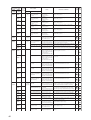
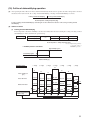
(7) Outline of cooling operation
(a)
Operation of major functional components in Cooling mode
Item
Functional
components
When the inverter
speed is 0rps
When the inverter speed
is other than 0rps
When the inverter speed is 0rps
due to an anomalous stop
Indoor fan motor
ON
ON
OFF
Flaps
ON or OFF
ON or OFF
Stop position control
Display
Lights up
Lights up
Lights up or flashes
52C
ON
ON
OFF after stop mode
Outdoor fan motor
OFF (20, 25, 35 type)
Depending on the stop mode (50 type)
ON
OFF (20, 25, 35 type)
Depending on the stop mode (50 type)
4-way valve
Electronic expansion valve
Depending on the stop mode
ON
Depending on the EEV control
Depending on the stop mode
23
(b) Air flow selection
(i)
Speed of inverter changes within the range of selected air flow.
Model
SRK20ZD-S
Air flow selection
Inverter command speed
Auto
Air flow
20~60rps
SRK50ZC-S
20~62rps
20~86rps
15~85rps
20~86rps
7th speed fixed
Inverter command speed
20~58rps
5th speed fixed
Inverter command speed
15~60rps
3rd~5th speed
20~34rps
20~38rps
Air flow
15~85rps
5th~7th speed
20~52rps
Air flow
LO
SRK50ZD-S
SRK35ZC-S
20~62rps
Air flow
MED
SRK35ZD-S
SRK25ZC-S
Depends on inverter command speed.
Inverter command speed
HI
(ii)
20~60rps
SRK25ZD-S
15~30rps
2nd speed fixed
When any protective function actuates, the operation is performed in the mode corresponding to the function.
(iii) Outdoor blower is operated in accordance with the inverter command speed.
(c) Detail of control in each mode (Pattern)
(i)
Fuzzy operation
During the fuzzy operation, the air flow and the inverter speed are controlled by calculating the difference between the room
temperature setting correction temperature and the suction air temperature.
(ii)
Cooling thermostat operation
1)
Operating conditions
During the cooling fuzzy operation or when the speed obtained by the fuzzy calculation is less than -24 rps.
2)
Detail of operation
Model
SRK20, 25, 35ZD-S
SRK50ZD-S
SRK25, 35ZC-S
SRK50ZC-S
0 rps [Comp. stopped]
10rps [10sec.] → 0rps [Comp. stopped]
Item
Inverter speed
Indoor fan
Corresponds to fan speed switch.
Outdoor fan
2nd speed [1min.] → stop
Stop
(iii) Cooling “HI POWER” operation (HI POWER button on remote controller: ON)
The unit is operated continuously for 15 minutes regardless of the setting temperature.
1)
Detail of operation
Model
Item
SRK20ZD-S
Inverter speed
SRK25ZD-S
SRK35ZD-S
SRK50ZD-S
SRK25ZC-S
SRK35ZC-S
SRK50ZC-S
62
86
60
Indoor fan
85
7th speed
Outdoor fan
4th speed
2nd speed
Notes (1) Protective functions will actuate with priority even during the “HI POWER” operation.
(2) Room temperature is not adjusted during the “HI POWER” operation
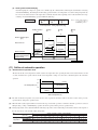
(8) Outline of dehumidifying operation
(a) After operating the indoor blower for 20 seconds from immediately after the start of operation, the indoor temperature is checked
and, based on the result of check, the cooling oriented dehumidifying or heating oriented dehumidifying is selected.
Heating oriented dehumidifying
Low
Cooling oriented dehumidifying
–3
High
Room temperature - Setting temperature (deg)
Cooling or heating oriented dehumidifying is selected again one hour after the first selection of the cooling or heating oriented
dehumidifying.
24
(b) Outline of control
(i)
Cooling oriented dehumidifying
Room temperature is checked at 5-minute intervals after selecting the cooling or heating oriented dehumidifying in order to
determine the operation range.
Operation range
D (D )
C (C)
Low
B (C)
–1
Note (1)
A (B)
0
+2
High
Figures in the parentheses
( ) show the values at
economical operation.
Room temperature – Setting temperature (deg)
D range
C range
B range
A range
Operation pattern
20, 25, 35 type : 50
50 type : 40
20, 25, 35 type : 38
50 type : 24
Inverter speed
20, 25, 35 type : 30
50 type : 15
0
50 type :
4th speed
5th speed
25 sec.
2nd speed
Indoor fan
1st speed
OFF
50 type :
1st speed
50 type :
1st speed
50 type :
1st speed
3rd speed
Outdoor fan
OFF
5 min.
Determination of cooling
oriented dehumidifying
operation range
5 min.
5 min.
5 min.
Temperature check
(ii) Heating oriented dehumidifying
After interrupting the compressor operation for 3 minutes (by the 3-minute timer) following the determination of heating
oriented dehumidifying, the unit begins in the heating operation. If the room temperature exceeds the setting temperature by
2ºC or more, the unit checks the room temperature at 5-minute intervals and, depending on the result, determines the range of
heating oriented dehumidifying operation.
Note (1)
Operation range
O
Low
(O )
L
–1
(L)
M (L)
0
Figures in the parentheses
( ) show the values at
economical operation.
High
Room temperature – Setting temperature (deg)
Operation pattern
Heating operation
O range
L range
M range
20, 25, 35 type : 38
50 type : 28
20, 25, 35 type : 48
50 type : 44
20, 25, 35 type : 30
50 type : 15
Inverter speed
0
Indoor fan
4th speed
4th speed
25 sec.
2nd speed
1st speed
OFF
Outdoor fan
3rd speed
OFF
Determination of heating
oriented dehumidifying
operation range
50 type :
1st speed
Depends on
the operation
condition
5 min.
50 type :
1st speed
50 type :
1st speed
5 min.
5 min.
Temperature check
25
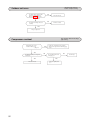
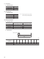
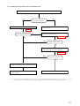
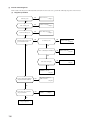
(9) Outline of automatic operation
(a)
Determination of operation mode
The unit checks the room temperature and the outdoor air temperature after operating the indoor and outdoor blowers for 20
seconds, determines the operation mode and the room temperature setting correction value, and then begins in the automatic
operation.
27.5
Cooling
25.5
Dehumidifying
Room temperature (˚C)
19.5
Heating
30
18
Outdoor temperature (˚C)
(b) The unit checks the temperature every hour after the start of operation and, if the result of check is not same as the previous
operation mode, changes the operation mode.
(c) When the unit is started again within one hour after the stop of automatic operation or when the automatic operation is selected
during heating, cooling or dehumidifying operation, the unit is operated in the previous operation mode.
(d) Setting temperature can be adjusted within the following range. There is the relationship as shown below between the signals of
the wireless remote controller and the setting temperature.
Signals of wireless remote controller (Display)
Setting
temperature
–6
–5
–4
–3
–2
–1
±0
+1
+2
+3
+4
+5
+6
Cooling
19
20
21
22
23
24
25
26
27
28
29
30
31
Dehumidifying
19
20
21
22
23
24
25
26
27
28
29
30
31
Heating
20
21
22
23
24
25
26
27
28
29
30
31
32
(10) Economical operation (ECONO button on remote controller: ON)
(a) The set temperature is raised by 1.5ºC (0.5ºC every one hour) at cooling operation and lowered by 2.5ºC (Steps of 1ºC, 1ºC and
0.5ºC every one hour) at heating operation to continue the operation with the following contents.
(b) Detail of operation
Model
SRK20ZD-S, 25ZD-S
SRK35ZD-S
SRK50ZD-S
SRK25ZC-S
SRK35ZC-S
SRK50ZC-S
Item
Operation mode
Cooling
Heating
Cooling
Heating
Cooling
Heating
Inverter command speed
20~52rps
20~72rps
20~58rps
20~76rps
15~60rps
15~62rps
2nd, 5th speed
4th, 6th speed
2nd, 5th speed
4th, 6th speed
3rd~5th speed
Indoor fan
Outdoor fan
3rd speed
4th, 5th speed
1st speed
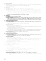
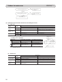
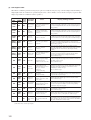
(11) Protective control function
(a) Frost prevention for indoor heat exchanger (During cooling or dehumidifying)
(i)
(ii)
Operating conditions
1)
Indoor heat exchanger temperature (detected with Th2) is lower than 5ºC.
2)
10 minutes after reaching the inverter command speed except 0 rps.
Detail of anti-frost operation
Item
Indoor heat exchanger
temperature
Indoor command speed
5°C or lower
40 rps (Type 50: 15 rps)
2.5°C or lower
40 rps
(Type 50: 15rps)
0rps
Indoor fan
Depends on operation mode
20~35: Max 2nd
50: Max 3rd
Outdoor fan
Depends on operation mode
OFF
4-way valve
OFF
Depends on stop mode
(iii) Reset conditions: 40 rps (Type 50: 15 rps) After 5 minutes of operation,
the indoor heat exchanger temperature (Th2) is 8ºC or higher.
26
Inverter
command
speed
0 rps
2.5
5
8
Indoor heat exchanger
temperature (°C)
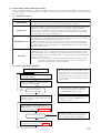
(b) Indoor fan motor protection
When the air conditioner is operating and the indoor fan motor is turned ON, if the indoor fan motor has operated at 300 rpm or
under for more than 30 seconds, the unit enters first in the stop mode and then stops the entire system.
TIMER light illuminates simultaneously and the RUN light flashing 6 times at each 8-second.
(c)
Dew condensation prevention control [Cooling (including automatic), cooling oriented dehumidifying operation)
◆ SRK50ZD-S, 50ZC-S
(i)
Operating conditions: When the following conditions are met after 20 minutes or more of continuous operation after
operation starts.
1 The command speed is 28 rps or higher
2 The humidity sensor value is 68% or higher
(ii)
Inverter command speed at upper limit
Operation contents
30 rps
Type
SRK50ZD-S, 50ZC-S
Item
50 rps
Fan Speed Medium
Indoor fan speed
4th speed
Fan Speed Low
Indoor fan speed
4th speed
Other Settings
Indoor fan speed
Corresponding to command speed
68
73
Humidity (%)
(iii) Reset Conditions: When either of the following conditions is satisfied.
1 The command speed is lower than 28 rps.
2 The humidity sensor value is less than 63%.
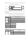
(d) Prevention of continuous low speed operation: For oil return to compressor
(i)
Operating conditions: When command speed of less than 30(26) rps continues for 8(60) minutes
(ii) Detail of operation: The unit is operated at command speed of 30 rps forcibly for 15 seconds. (The indoor and outdoor
fans are not changed.)
Notes (1) When the command of exceeding 30 rps is directed during 30 rps forced operation, the unit follows it.
Note (2) Values in ( ) are for Type 50.
(e)
Compressor protection start
(i)
When the indoor unit calculated speed is 64 rps or over at operation start, the unit is operated with 64 rps for 1 minute and 45
seconds. (All models) After that when the calculated speed is 96 rps or over, the unit is operated with 96 rps for 5 minutes
then moved to command speed. (50 type only)
(ii) At thermo operation (OFF → ON) this control is not executed.
(iii) The indoor unit fan corresponds to the command speed of each operation mode.
Note (1) When the calculated speed is less than 64 rps, the unit is started with low load starting described in article (f).
(f)
Low load starting
(i)
When the unit is started with calculated speed of less than 60(30) rps, it is operated with 60(30) rps for 80(60) seconds, then
the operation is moved to the command speed.
(ii) The indoor fan corresponds to the operation mode.
Cooling: Speed corresponding to the command speed of air flow switching
Dehumidification: Speed decided in the operation region
Heating: The lower one between the speed corresponding to the command speed and the hot keep speed
Note (1)
Values in ( ) are for Type 50.
27
(g) Inching prevention
When the compressor goes into the thermo operation within 10(5) minutes since operation start or becomes various dehumidifying
operations, the operation is continued with the command speed of 20(15) rps forcibly.
Note (1) Values in ( ) are for Type 50.
(h) Current safe
(i)
Purpose: Current is controlled not to exceed the upper limit of the setting operation current.
(ii)
Detail of operation: Input current to the converter is monitored with the current sensor fixed on the printed circuit board
of the outdoor unit and, if the operation current value reaches the limiting current value, the inverter speed is reduced.
If the mechanism is actuated when the speed of outdoor unit is less than 30 rps, the compressor is stopped immediately.
Simultaneously, a red LED on the printed circuit board provided on the outdoor unit controller flashing 3 times for 0.5 second
at intervals of 8 seconds. Operation starts again after a delay time of 3 minutes.
(i)
Current cut
(i)
Purpose: Inverter is protected from overcurrent.
(ii)
Detail of operation: Output current from the converter is monitored with a shunt resistor and, if the current exceeds the
setting value, the compressor is stopped immediately. Simultaneously, a red LED on the printed circuit board provided on the
outdoor unit controller flashing for 0.5 second at intervals of 8 seconds. Operation starts again after a delay time of 3 minutes.
(j)
Heating overload protective control
(i)
Operating conditions : When the unit is operating with the outdoor unit speed other than 0 rps or when the outdoor air
(ii)
Detail of operation
temperature (detected by Th5) rose beyond 17ºC for 30 seconds continuously.
1) Indoor fan speed is raised forcibly by 1 step.
2) Taking the upper limit of control speed range at 60 rps, if the output speed obtained with the fuzzy calculation exceeds the
upper limit, the upper limit value is maintained.
3) The outdoor fan is set on 2nd speed. (20, 25, 35 types only)
4) The lower limit of control speed is set to 40(35) rps and even if the calculated result becomes lower than that after fuzzy
calculation, the speed is kept to 40(35) rps. However, when the thermo becomes OFF, the speed is reduced to 0 prs.
(iii) Reset conditions: When the outdoor air temperature drops below 16ºC.
Note (1) Values in ( ) are for Type 50.
(k) Cooling overload protective control
(i)
Operating conditions: When the outdoor unit is operating with the speed of other than 0 rps, or when the outdoor air
(ii)
Detail of operation
temperature (detected by Th5) becomes 41ºC or over for 30 seconds continuously.
1) Outdoor fan is stepped up by 3(1) speed step.
2) The lower limit of control speed is set to 30 rps and even if the calculated result becomes lower than that after fuzzy
calculation, the speed is kept to 30 rps. However, when the thermo becomes OFF, the speed is reduced to 0 rps.
3) The upper limit of control speed is 72 rps.
(iii) Restoration condition: When the outdoor air temperature becomes 40ºC or less
Note (1) Values in ( ) are for Type 50.
(l)
Freezing cycle system protective control
(i)
Operating conditions: When both of following conditions have continued for more than 5 minutes later than 5 minutes
after the start of operation.
1) Command speed is higher than 60 rps
2) During cooling, dehumidifying: Indoor heat exchanger temperature - Room temperature > – 4ºC
During heating: Indoor heat exchanger temperature - Room temperature < 6ºC
(ii)
Detail of operation
The command speed repeats 30 minutes at 30rps ↔ 2 minutes at 62 rps.
(iii) Restoration conditions: When the condition becomes outside of either conditions 1) or 2) shown above
Note (1) This control is valid when the room air temperature is in the range of 10 to 40ºC at cooling and dehumidification operation and 0 to 40ºC at heating
operation.
28
(m) Compressor overheat protection
(i) Purpose: It is designed to prevent deterioration of oil, burnout of motor coil and other trouble resulting from the compressor
overheat.
(ii) Detail of operation
1) Speeds are controlled with temperature detected by the sensor mounted on the discharge pipe.
(Example) Fuzzy
4 rps (1)
After lapse of 3 min. or over (3)
After lapse of 3 min. or over (3)
4 rps
Lower limit (4)
After lapse of 3 min. or over (3)
0 rps
90
(80)
100
(90)
125
(110)
Discharge pipe temperature (˚C)
Notes (1)
(2)
(3)
(4)
When the discharge pipe temperature is in the range of 100(90) to 125(110)ºC, the speed is reduced by 4 rps.
When the discharge pipe temperature is raised and continues operation for 20 seconds without changing, then the speed is reduced again by 4 rps.
If the discharge pipe temperature is still 90 (80) ºC or greater but less than 100 (90) ºC even when the inverter command speed is maintained for 3
minutes when the temperature is 90 (80) ºC or greater but less than 100 (90) ºC, the speed is raised by 2 rps and kept at that speed for 3 minutes. This
process is repeated until the command speed is reached.
Lower Limit Speed
Cooling
(5)
Heating
20, 25, 35 type
20
30
50 type
22
38
Values in ( ) are for Type 50.
2) If the temperature of 125(110)ºC is detected by the sensor on the discharge pipe, then the compressor will stop immediately.
Simultaneously, the red LED on the printed circuit board of outdoor unit controller flashing 5 times for 0.5 second at
interval of 8 seconds.When the discharge pipe temperature drops and the time delay of 3 minutes is over, the unit starts
again within 1 hour but there is no start at the third time.
(n) Serial signal transmission error protection
(i) Purpose: Prevents malfunction resulting from error on the indoor ↔ outdoor signals.
(ii) Detail of operation: When the indoor unit controller ↔ outdoor unit controller signals cannot be received, the compressor
is stopped immediately. Simultaneously, the red LED on the printed circuit board of outdoor unit controller flashing 6 times
for 0.5 second at intervals of 8 seconds. Once the operation stops, it does not start any more.
(TIMER light on the indoor unit flashing at the same time.)
(o) High pressure control
(i) Purpose: Prevents anomalous high pressure operation during heating.
(ii) Detector: Indoor unit heat exchanger sensor (Th2)
(iii) Detail of operation:
(Example) Fuzzy
8 rps(1)
After lapse of 20 Sec. or over (2)
8 rps
After lapse of 20 Sec. or over (2)
After lapse of 20 Sec. or over
(2)
Lower limit
speed 20(35)rps
0 rps
A
B
Indoor unit heat exchanger temperature (˚C)
C
Notes (1) When the indoor unit heat exchanger temperature is in the range of B~C ºC, the speed is reduced by 8 rps at each 20 seconds. When the temperature is C
ºC or over for 1 minute continuously, the inverter is stopped.
(2) When the indoor unit heat exchanger temperature is in the range of A~B ºC, if the inverter command speed is been maintained and the operation has
continued for more than 20 seconds at the same speed, it returns to the normal heating operation.
(3) Indoor blower retains the fan tap when it enters in the high pressure control. Outdoor blower is operated in accordance with the speed.
¡ Temperature list
Unit : ºC
A
B
C
RPSmin < 40(88)
40(88) <= RPSmin < 50(108)
48 (48.5)
53 (56)
58 (61)
48 (44)
53 (51.5)
58 (56.5)
50(108) <
= RPSmin
48.5 (39)
56 (46.5)
61 (51.5)
Notes (1) RPSmin: The lower one between the outdoor unit speed and the command speed
Note (2) Values in ( ) are for Type 50.
29
(p) Heating low outdoor temperature protective control (50 type only)
◆ <I>
(a) Operating conditions: When the outdoor air temperature sensor (Th5) is 4ºC or lower continues for 5 minutes while the
outdoor speed is other than 0 rps.
(b) Operation content:
When the command speed is less than 22 rps, the command speed is forcibly set at 22 rps.
(c) Reset conditions:
When the outdoor air temperature sensor (Th5) becomes 6ºC or higher.
◆ <II>
(a) Operating conditions: When the outdoor air temperature sensor (Th5) is 0ºC or lower continuously for 5 minutes while
the outdoor speed is other than 0 rps.
(b) Operation content:
The outdoor fan motor speed is raised to the next higher speed. (Upper limit 2nd speed)
(c) Reset conditions:
When the outdoor air temperature sensor (Th5) becomes 2ºC or higher.
◆
<III>
(a) Operating conditions: When the temperature sensed by the outdoor heat exchanger sensor (Th4) becomes –10ºC or
lower continuously for 1 minute.
(b) Operation content:
When the command speed upper limit is set at 70 rps.
(c) Reset conditions:
When the temperature sensed by the outdoor heat exchanger sensor (Th4) becomes -7ºC or higher.
(q) Stop mode
(i)
Operating conditions: When the operation mode is changed, when the dehumidifying operation is changed from the
heating oriented mode to the cooling oriented mode or vice versa, or when the inverter speed turns to 0 rps. [When 0 rps is
commanded from the indoor unit controller, or when an outdoor protective function is actuated]
(ii) Detail of operation
◆ 20~35 type
When stopped by indoor unit controller
Function
Operation
Inverter
speed
(Command
speed)
0
Indoor
fan
(Speed
dependent)
OFF
Indoor
power
relay
ON
Outdoor
fan
4-way
valve
Heating, heating
oriented dehumidifying
3 min.(1)
3 min.(1)
When stopped or reset by outdoor unit protective function
Heating, heating
oriented dehumidifying
2 min.
55 sec.
Cooling, cooling
oriented dehumidifying
2 min.
55 sec.
Hot keep
1st speed
OFF
ON
OFF
ON
2 min.55sec.
OFF
Stop
Full stop
(0 rps command)
30
Cooling, cooling
oriented dehumidifying
Stop
Full stop
(0 rps command)
Stop
(0 rps command)
Restart
Stop
Restart
(0 rps command)
◆ 50 type
When stopped by indoor unit controller
Function
Operation
Inverter
speed
(Command
speed)
0
Indoor
fan
(Speed
dependent)
OFF
Indoor
power
relay
Outdoor
fan
4-way
valve
Heating, heating
oriented dehumidifying
Cooling, cooling
oriented dehumidifying
3 min.(1)
When stopped or reset by outdoor unit protective function
Heating, heating
oriented dehumidifying
3 min.(1)
3 min.
Cooling, cooling
oriented dehumidifying
2 min.
55 sec.
Hot keep
1st speed
ON
OFF
2nd speed
ON
OFF
ON
2nd speed
1 min.
1 min.
1 min.
1 min.
2nd speed
2nd speed
2 min.55sec.
2 min.55sec.
OFF
Stop
Full stop
(0 rps command)
Stop
Full stop
(0 rps command)
Stop
(0 rps command)
Restart
Stop
Restart
(0 rps command)
Note (1) When the start delay of compressor of indoor unit controller is actuated and the operation is reset, it takes 2 minutes and 55 seconds.
31
1.1.5 APPLICATION DATA
SAFETY PRECAUTIONS
¡ Please read these “Safety Precautions” first then accurately execute the installation work.
¡ Though the precautionary points indicated herein are divided under two headings,
WARNING and
CAUTION , those points
which are related to the strong possibility of an installation done in error resulting in death or serious injury are listed in the
WARNING section. However, there is also a possibility of serious consequences in relationship to the points listed in the
CAUTION section as well. In either case, important safety related information is indicated, so by all means, properly observe all
that is mentioned.
¡ After completing the installation, along with confirming that no abnormalities were seen from the operation tests, please explain
operating methods as well as maintenance methods to the user (customer) of this equipment, based on the owner’s manual.
Moreover, ask the customer to keep this sheet together with the owner’s manual.
WARNING
¡ To disconnect the appliance from the mains supply this appliance must be connected to the mains by means of
a circuit breaker or a switch (use a recognized 16A) with a contact separation of at least 3mm.
¡ The appliance shall be installed in accordance with national wiring regulations.
¡ This system should be applied to places as households, residences and the like. Application to inferior environment such as engineering shop could cause equipment malfunction.
¡ Please entrust installation to either the company which sold you the equipment or to a professional contractor.
Defects from improper installations can be the cause of water leakage, electric shocks and fires.
¡ Execute the installation accurately, based on following the installation manual. Again, improper installations can
result in water leakage, electric shocks and fires.
¡ For installation, confirm that the installation site can sufficiently support heavy weight. When strength is insufficient, injury can result from a falling of the unit.
¡ For electrical work, please see that a licensed electrician executes the work while following the safety standards
related to electrical equipment, and local regulations as well as the installation instructions, and that only exclusive use circuits are used.
Insufficient power source circuit capacity and defective installment execution can be the cause of electric shocks
and fires.
¡ Accurately connect wiring using the proper cable, and insure that the external force of the cable is not conducted
to the terminal connection part, through properly securing it improper connection or securing can result in heat
generation or fire.
¡ Take care that wiring does not rise upward ,and accurately install the lid/service panel.It’s improper installation
can also result heat generation or fire.
¡ When setting up or moving the location of the air conditioner, do not mix air etc. or anything other than the
designated refrigerant within the refrigeration cycle.
Rupture and injury caused by abnormal high pressure can result from such mixing.
¡ Always use accessory parts and authorized parts for installation construction. Using parts not authorized by this
company can result in water leakage, electric shock, fire and refrigerant leakage.
¡ Ventilate the work area when refrigerant leaks during the operation.
Coming in contact with fire, refrigerant could generate toxic gas.
¡ Confirm after the foundation construction work that refrigerant does not leak.
If coming in contact with fire of a fan heater, a stove or movable cooking stove, etc., refrigerant leaking in the
room could generate toxic gas.
¡ In joining pipes, do not use conventional (R22) pipng flare nuts, etc. The use of conventional pipng materials may
lead to the rapture of piping due to higher pressure used for the refrigerant cycle and possible personal injury.
(Use only piping material designed specifically for R410A)
CAUTION
¡ Execute proper grounding. Do not connect the ground wire to a gas pipe, water pipe, lightning rod or a telephone
ground wire.
Improper placement of ground wires can result in electric shock.
¡ The installation of an earth leakage breaker is necessary depending on the established location of the unit.
No installing an earth leakage breaker may result in electric shock.
¡ Do not install the unit where there is a concern about leakage of combustible gas.
The rare even of leaked gas collecting around the unit could result in an outbreak of fire.
¡ For the drain pipe, follow the installation manual to insure that it allows proper drainage and thermally insulate it
to prevent condensation. Inadequate plumbing can result in water leakage and water damage to interior items.
32
(1) Selection of location for installation
(a)
Indoor unit
(i)
Where there is no obstructions to the air flow and where the cooled
air can be evenly distributed.
(ii) A solid place where the unit or the wall will not vibrate.
(iii) A place where there will be enough space for servicing. (Where
6.5 cm
space mentioned below can be secured)
10 cm
(iv) Where wiring and the piping work will be easy to conduct.
(v)
The place where receiving part is not exposed to the direct rays of
5 cm
the sun or the strong rays of the street lighting.
1.5 cm
(b) Outdoor unit
(i)
A place where good air circulation can be obtained.
(ii) A place where the exhausted air will not be sucked in for the second time.
(iii) A place where the unit will not be affected by other heat sources. (When there are several units installed or another heat
source)
(iv) Do not install the unit near the seaside, or where there is possibility of chlorine gas generation.
(v)
A place where discharged hot and cold air or unit’s operating sound will not be a nuisance to the neighborhood.
(vi) A place where servicing space can be secured.
100
Unit : mm
Air inlet
No obstacles
(Service space
for electrical
parts)
Air
Outlet
60
Air inlet
100
Note (1) If the wall is higher than 1.2 m or a ceiling is
present, distances larger than indicated in the above
table must be provided.
(vii) A place where vibration will not be enlarged.
Snow hood
(viii) In heating operation, snow deposit on the heat-exchanger of outdoor unit must be
prevented for keeping the normal performance capacity.
1)
Snow-hood on outdoor unit as in drawing, will reduce the frequency of
defrost operation.
When installing the snow hood, take care so that the air outlet of the snow
Height:
Must be over
the possible
snow deposit
height
hood will not face directly into the most windy direction.
2)
(c)
Design the base higher than possible snow deposit.
Limitations for one way piping length and vertical
height difference.
Model
Item
One way piping length (R)
Vertical
height
difference (h)
Outdoor
unit is lower
Outdoor unit
is higher
20~35 type
50 type
15 m
25 m
10 m
15 m
10 m
15 m
h
33
(2) Installation of indoor unit
(a) Installation of installation board
(i)
Fixing of installation board
Look for the inside wall structures (Intersediate support or
pillar and firaly install the unit after level surface has been
checked.)
450
Adjustment of the installation board in the horizontal
direction is to be conducted with four screws in a
temporary tightened state.
Standard hole
Adjust so that board will be level by turning the board
with the standard hole as the center.
Mating mark for level surface
Fixing on concrete wall
Use of nut anchor
Use of bolt anchor
Nut
(M6)
Bolt
(M6 × 12)
Mounting
board
Max. 10
Mounting
board
(b) Drilling of holes and fixture sleeve (Option parts)
When drilling the wall that contains a metal lath, wire lath or metal plate, be sure to use pipe hole sleeve sold separately.
(i)
Drill a hole with ø65
(ii)
Adjusting sleeve length
whole core drill
Cut off the sleeve
collar in case of
drawing piping out
to rear.
Indoor side
Cut off the sleeve
collar that can be
seen from beneath
the unit.
Outdoor side
Wall thickness
+ 1.5 cm
Note (1) Drill a hole with incline of 5 degree from
indoor side to outdoor side.
(iii) Install the sleeve
(Inserting sleeve)
(*Sleeve + *Inclined + *Sealing plate)
View of sleeve when installed
Turn to
tighten
Sleeve
Inclined
flange
Sealing
plate
Paste
Indoor side
34
Outdoor side
Indoor side
Outdoor side
(c)
Preparation of indoor unit
(i)
Mounting of connecting wires
1) Remove the lid (R).
2) Remove the terminal cover.
3) Remove the wiring clamp.
4) Connect the connecting wire securely to the terminal block.
Terminal block
Use cables for interconnection wiring to avoid loosening of the
wires.
CENELEC code for cables. Required field cables.
H05 RNR3G1.5 (Example) or 245IEC57
H Harmonized cable type
05 300/500 volts
R Natural-and/or synth, rubber wire insulation
N Polychloroprene rubber conductors insulation
R Standed core
4or5 Number of conductors
G One conductor of the cable is the earth conductor (yellow/
green)
1.5 Section of copper wire (mm2)
Clamp
Terminal
cover
Lid (R)
1 Connect the connection wire securely to the terminal block. If the wire is not affixed completely, contact will be
poor,and it is dangerous as the terminal block may heat up and catch fire.
2 Take care not to confuse the terminal numbers for indoor and outdoor connections.
3 Affix the connection wire using the wiring clamp.
5) Fix the connecting wire by wiring clamp.
6) Attach the lid.
7) Close the suction grille.
(ii)
Protective taping (Protect the cable with tape at the section where the cable passes through the hole opened on the wall.)
(iii) Forming of pipe (Holding down the pipe at the root, change the pipe direction, extend it and adjust according to the
circumstance.)
[When the pipe is extended to left and taken out from the rear center]
(Drain pipe relocation procedure)
1. Remove the drain pipe. 2. Remove the drain cap. 3. Insert the drain cap.
¡ Loosen the spring ¡ Remove by hand or
clamp to remove.
use cutting pliers, etc.
¡ Securely insert the
drain cap removed in
the step 2.
Note: If it is inserted in
sufficiently, water
leakage could result.
Since this air conditioner has been designed to collect dew
drops on the rear surface to the drain pan, do not attach the
power cord above the gutter.
4. Connect the drain pipe.
¡ Loosen the spring
clamp and securely
insert the drain pipe.
Note: If it is inserted insufficiently, water
leakage could result.
Gutter
Wall
Pipe accommodation section
35
(d) Installation on indoor unit
(i) Install the indoor unit on the mounting plate.
Hook the upper part of the indoor unit on the stoppers disposed at the upper part of the mounting plate and lightly push the
lower part of the indoor unit so that the unit is fixed in position.
¡ When removing the indoor unit
1) Disconnect the lid at right and left.
Mounting
plate
2) Pull down the stoppers (right and left) proWall
vided at the bottom of the indoor unit base.
(See the detail view shown at right.)
Light push
(ii) Be sure not to leave any trap on the drain pipe.
Declining slope
Inverted slope
Indoor unit base bottom stopper
(2 places at right, left)
Trap
(3) Installation of outdoor unit
(a) Installation of outdoor unit
(i) Make sure that sufficient space for installation and service is secured.
(ii) Fix the leg sections of the unit on a firm base which will not play.
Attach cushion pads, etc. between the unit and the mounting fixtures not to transmit vibration to the building.
(iii) Attach a drain elbow, etc. under the drain port of the bottom plate to guide drain water.
(Drain elbow should not be used where days when temperature drops below 0°C continue for several days. Draining may be
disturbed by frozen water.)
(iv) When installing the unit at a higher place or where it could be toppled with strong winds, secure the unit firmly with
foundation bolts, wire, etc.
(b) Connection of indoor and outdoor connecting wiring
(i) Connect the wiring according to the number of the indoor terminal block. (Mis-wiring may cause the burning damage, and
make sure to connect correctly.)
Terminal block
1 Brown
2 Blue
3 Black
Yellow/Green
For power supply, indoor outdoor
Connecting wiring
Indoor/outdoor signal wire (Low voltage)
Earth wiring terminal
Interconnecting
wire
Notes (1) To prevent the mis-operation by noise, when the connecting wire too long for indoor and outdoor. Please hide the fixed wire in the pipe or use vinyl tape to set.
Do not put wire into the unit.
Notes (2) Please let the anchorized personal to decide by indoor wiring code whether connect the leakage breaker or not.
(4) Refrigerant piping
(a) Preparation
Keep the openings of the pipes covered with tapes etc. to prevent dust, sand, etc. from entering them.
Indoor unit side
(Do not
turn)
¡ Remove the flared nuts.
(on both liquid and gas sides)
36
Outdoor unit side
Press
Remove
Remove
¡ Remove the flared nuts.
(on both liquid and gas sides)
Dimension A
Liquid side
(φ6.35): 9.1 dia
Gas side
(φ9.52): 13.2 dia
(φ12.7): 16.6 dia
¡ Install the removed flared nuts to the pipes to be connected,
then flare the pipes.
(b) Connection of refrigerant piping
Indoor unit side
Outdoor unit side
¡ Connect firmly gas and liquid side
¡ Connect firmly gas and liquid side
pipings by Torque wrench.
pipings by Torque wrench.
Spanner
(for fixing
the piping)
Torque
wrench
¡ Specified torquing value:
¡ Specified torquing value:
Liquid side (ø6.35) : 14.0~18.0N·m (1.4~1.8kgf·m)
Liquid side (ø6.35) : 14.0~18.0N·m (1.4~1.8kgf·m)
Gas side (ø9.52)
: 34.0~42.0N·m (3.4~4.2kgf·m)
Gas side (ø9.52)
: 34.0~42.0N·m (3.4~4.2kgf·m)
(ø12.7)
: 49.0~61.0N·m (4.9~6.1kgf·m)
(ø12.7)
: 49.0~61.0N·m (4.9~6.1kgf·m)
¡ Use one more spanner to fix the valve.
¡ Always use a Torque wrench and back up spanner to tighten the flare nut.
(c)
Air purge
(i)
Tighten all flare nuts in the pipings both indoor and outside will so as not to cause leak.
(ii)
Connect service valve, charge hose, manifold valve and vacuum pump as is illustrated below.
(iii) Open manifold valve handle Lo to its full width, and perform vacuum or evacuation.
Continue the vacuum or evacuation operation for 15 minutes or more and check to see that the vacuum gauge reads – 0.1 MPa
(– 76 cmHg).
(iv) After completing vacuum operation, fully open service valve (Both gas and liquid sides) with hexagon headed wrench.
(v)
Check for possible leakage of gas in the connection parts of both indoor and outdoor.
Service Valve
(two-way valve)
Compound
pressure
gauge
–0.1MPa
(–76cmHg)
Service Valve
(three-way valve)
Service Port
Pressure
gauge
Gauge Manifold
(Designed specifically for R410A)
Handle Hi.
Handle Lo
Charge hose
(Designed specifically for R410A)
Vacuum pump
Charge hose
(Designed specifically for R410A)
Vacuum pump adapter
(Anti-reverse flow type)
(Designed specifically for R410A)
¡ Since the system uses service ports differing in diameter from those found on the conventional models, a charge hose (for R22)
presently in use is not applicable.
Please use one designed specifically for R410A
¡ Please use an anti-reverse flow type vacuum pump adapter so as to prevent vacuum pump oil from running back into the system.
Oil running back into an air-conditioning system may cause the refrigerant cycle to break down.
Additional refrigerant charge
¡ 20~35 type
Additional refrigerant charge is not required at all.
¡ 50 type
When refrigerant piping exceeds 15m conduct additional refrigerant charge by weight after refrigerant piping completion.
Additional charge amount per meter = 20g/m
[Example]
How much amount of additional charge for 25m piping?
(25 – 15)m × 20g/m = 200g
200g for additional charge
37
(d) Insulation of connecting portion
(i)
Cover the connecting portion of the refrigerant piping with the pipe cover and seal them.
If neglecting to do so, moisture occurs on the piping and water will drip out.
To cover the connecting portion with
insulation material materials, cut upper portion
and then seal it with insulation materials.
Vinyl tape
(ii)
Finishing and fixing
1)
Insulation
Refrigerant piping
Electrical wiring
Covering tape
Drain hose
Tie up the piping with wrapping tape, and shape it so
that it conforms to which the pipe is attached.
2)
Fix them with clamps as right figure.
Cover the exterior portion with covering tape and shape the piping so
it will match the contours of the
route that the piping to take. Also
fix the wiring and pipings to the
wall with clamps.
Tapping screw
(5) Test run
(a) Conduct trial run after confirming that there is no gas leaks.
(b) When conducting trial run set the remote controller thermostat to continuous operation position. However when the power source
is cut off or when the unit’s operation switch is turned off or was turned to fan operation position, the unit will not go into operation
in order to protect the compressor.
(c) Insert in electric plug into the electric outlet and make sure that it is not loose.
(i)
When there is something wrong with the electric outlet and if the insertion of the electric plug is insufficient, there may occur
a burn out.
(ii) It is very important to be careful of above when plugging in the unit to an already furnished electrical outlet.
(d) Explain to the customer on the correct usage of the air conditioner in simple layman’s terms.
(e) Make sure that drain flows properly.
(f)
Standard operation data
(220/230/240V)
Model
Item
High pressure (MPa)
Low pressure (MPa)
Temp. difference between
return air and supply air (°C)
Running current (A)
SRK20ZD-S
SRK35ZD-S
SRK50ZD-S
SRK35ZC-S
SRK50ZC-S
Cooling
–
–
–
–
Heating
2.5~2.7
2.5~2.7
2.8~3.0
3.2~3.3
Cooling
0.9~1.1
0.9~1.1
0.8~1.0
0.7~0.9
Heating
–
–
–
–
Cooling
13~15
13~15
13~15
14~16
Heating
18~20
18~20
18~20
24~26
Cooling
2.4/2.3/2.2
3.1/3.0/2.9
5.4/5.2/5.0
7.6/7.3/7.0
Heating
3.0/2.9/2.8
4.5/4.3/4.1
5.9/5.7/5.4
9.0/8.6/8.2
Note (1) The data are measured at following conditions
Ambient air temperature
Indoor side: Cooling ... 27˚C DB, 19˚C WB, Heating ... 20˚C DB
Outdoor side: Cooling ... 35˚C DB, 24˚C WB, Heating ... 7˚C DB, 6˚C WB
38
SRK25ZD-S
SRK25ZC-S
(6) Precautions for wireless remote controller installation and operation
(a)
Wireless remote controller covers the following distances:
(i)
When operating facing the air conditioner:
6
m
ss
le
or
Wireless remote
controller
5 m or less
(ii)
or les
s or le
ss
or less
When manipulating the remote controller mounted on
Notes (1) The remote controller is correctly facing the
sensing element of the air conditioner when being
manipulated.
(2) The typical coverage is indicated (in the left
illustration). It may be more or less depending on
the installation.
(3) The coverage may be less or even nil. If the sensing
element is exposed to strong light, such as direct
sunlight, illumination, etc., or dust is deposited on
it or it is used behind a curtain, etc.
Receiver
a wall:
Make sure that it works normally (i.e., transmission/reception
signal is audible) before mounting.
Remote controller
available in this area.
39
1.1.6 MAINTENANCE DATA
(1) Troubleshooting procedures for electrical equipment
(a) Cautions
1 If you are disassembling and checking an air conditioner, be sure to turn off the power before beginning. When working on
indoor units, let the unit sit for about 1 minute after turning off the power before you begin work. When working on an outdoor
unit, there may be an electrical charge applied to the main circuit (electrolytic condenser), so begin work only after discharging
this electrical charge (to DC 10 V or lower).
2 When taking out printed circuit boards, be sure to do so without exerting force on the circuit boards or package components.
3 When disconnecting and connecting connectors, take hold of the connector housing and do not pull on the lead wires.
(b) Items to check before troubleshooting
1 Have you thoroughly investigated the details of the trouble which the customer is complaining about?
2 Is the air conditioner running? Is it displaying any self-diagnosis information?
3 Is a power supply with the correct voltage connected?
4 Are the control lines connecting the indoor and outdoor units wired correctly and connected securely?
5 Is the outdoor unit’s refrigerant service valve open?
(c) Troubleshooting procedure (If the air conditioner does not run at all)
If the air conditioner does not run at all, diagnose the trouble using the following troubleshooting procedure. If the air conditioner
is running but breaks down, proceed to troubleshooting step (d).
Important
When all the following conditions are met, we say that the air conditioner will not run at all.
1 The RUN light does not light up.
2 The flaps do not open.
3 The indoor unit fan motors do not run.
4 The self-diagnosis display does not function.
Troubleshooting procedure (If the air conditioner does not run at all)
Is the correct voltage
connected for the power
supply?
NO
* If the voltage is correct, it will be
within the following voltage range.
198 ~ 264 V
Make sure the correct
voltage is connected, then
perform an operation check.
YES
With the power off, do
the flaps open manually,
then close again when
the power is turned on?
NO
Is the current fuse on the
indoor unit’s board blown?
YES
NO
YES
Proceed to the indoor unit
circuit board check.
Is there a reception
sound emitted from the
unit when it is operated
by the remote controller?
NO
YES
Replace the indoor unit’s
circuit board and perform an
operation check.
40
Proceed to the wireless remote
controller troubleshooting
procedure.
If the package components
are not damaged, replace
the fuse and perform an
operation check again.
(d) Troubleshooting procedure (If the air conditioner runs)
Confirm the contents of the customer complaint.
NO
The cause of the trouble can
be specifically identified.
Eliminate the cause of the trouble and perform an
operation check.
Check the self-diagnosis display.
See page 42.
Is an error code displayed by
the self-diagnosis function?
YES
NO
Using the Service Mode, access the self-diagnosis
displays generated in the past.
See pages 43~46.
YES
YES
Is there a history of selfdiagnosis display items?
NO
Using the Service Mode, access the stop history due
to protection control generated in the past.
See pages 43~46.
YES
Is there a history of stops due
to protection control? (1)
NO
Identify the faulty component by using the check
procedure corresponding to the content of the trouble.
Replace the faulty component, then perform an
operation check.
The air conditioning system is operating normally.
Note (1) Even in cases where only intermittent stop data are generated, the air conditioning system is normal. However, if the same protective operation recurs
repeatedly (3 or more times), it will lead to customer complaints. Judge the conditions in comparison with the contents of the complaints.
41
(e) Self-diagnosis table
When this air conditioner performs an emergency stop, the reason why the emergency stop occurred is displayed by the flashing of
display lights. If the air conditioner is operated using the remote controller 3 minutes or more after the emergency stop, the trouble
display stops and the air conditioner resumes operation. (2)
Indoor unit display panel
Description
of trouble
Cause
Display (flashing) condition
RUN
light
TIMER
light
ON
6 time
flash
Error of signal
transmission
• Defective power supply,
Broken signal wire, defective
in/outdoor unit boards
When there is no signal between the indoor unit’s board and outdoor
unit’s board for 10 seconds or longer (when the power is turned on), or
when there is no signal for 1 minute 50 seconds or longer (during
operation)(the compressor is stopped).
1 time
flash
ON
Heat exchanger
sensor error
• Broken heat exchanger sensor
wire, poor connector
connection
When a heat exchanger sensor wire disconnection is detected while
operation is stopped. (If a temperature of –20ºC or lower is detected for
15 seconds, it is judged that the wire is disconnected.) (Not displayed
during operation.)
2 time
flash
ON
Room temperature
sensor error
• Broken room temperature
sensor wire, poor connector
connection
When a room temperature sensor wire disconnection is detected while
operation is stopped. (If a temperature of –20ºC or lower is detected for
15 seconds, it is judged that the wire is disconnected.) (Not displayed
during operation.)
6 time
flash
ON
Indoor fan motor
error
• Defective fan motor, poor
connector connection
When conditions for turning the indoor unit’s fan motor on exist during
air conditioner operation, an indoor unit fan motor speed of 300 rpm or
lower is measured for 30 seconds or longer. (The air conditioner stops.)
ON
5 time
flash
Over heat of
compressor
• Gas shortage, defective
discharge pipe sensor, closed
service valve
When the value of the discharge pipe sensor exceeds the set value.
(The air conditioner stops.)
Keeps
flashing
2 time
flash
Outdoor heat
exchanger sensor
error
• Broken heat exchanger sensor
wire, poor connector
connection
When a sensor wire disconnection is detected while operation is
stopped. (If a temperature of –50ºC or lower is detected for 15 seconds,
it is judged that the wire is disconnected.) (Not displayed during
operation.)
Keeps
flashing
1 time
flash
Outdoor air
temperature sensor
error
• Broken outdoor air temp.
sensor wire, poor connector
connection
When an outdoor air temperature sensor wire disconnection is detected
while operation is stopped. (If a temperature of –40ºC or lower is
detected for 15 seconds, it is judged that the wire is disconnected.) (Not
displayed during operation.)
Keeps
flashing
4 time
flash
Discharge pipe
sensor error
• Broken discharge pipe sensor
wire, poor connector
connection
When a compressor discharge pipe sensor wire disconnection is detected
for 15 seconds or longer (less than 7ºC) after the outdoor unit’s speed
has continued at 0 rps or higher for 9 minutes.
(The air conditioner stops.)
ON
1 time
flash
Current Cut
ON
7 time
flash
Outdoor fan motor
error
(20, 25, 35 type
only)
• Compressor locking, open
phase on compressor output,
shortcircuit on power
transistor, closed service valve
The inverter output current (compressor motor current) exceeds the set
value during compressor start.
(The air conditioner stops.)
• Defective fan motor, poor
connector connection
When the outdoor unit’s fan motor speed continues for 30 seconds or
longer at 75 rpm or lower. (3 times) (The air conditioner stops.)
When there is an emergency stop caused by trouble in the outdoor unit,
or the input current value is found to be lower than the set value
continuously for 3 minutes or longer.
(The air conditioner stops.)
If the compressor motor’s magnetic pole positions cannot be correctly
detected when the compressor starts.
(The air conditioner stops.)
ON
2 time
flash
Trouble of outdoor
unit
• Broken power transistor,
broken compressor wire
• Broken discharge pipe sensor
wire, poor connector
connection
• Compressor blockage
2 time
flash
2 time
flash
Rotor lock
• Defective compressor
• Open phase on compressor
• Defective outdoor unit boards
Notes (1) There is no error indicator in the 20, 25 and 35 types.
Notes (2) The air conditioner cannot be restarted using the remote controller for 3 minutes after operation stops.
42
(f)
Service mode (Trouble mode access function)
This air conditioner is capable of recording error displays and protective stops (service data) which have occurred in the past. If
self-diagnosis displays cannot be confirmed, it is possible to get a grasp of the conditions at the time trouble occurred by checking
these service data.
(i) Explanation of terms
Term
Explanation
Service mode
The service mode is the mode where service data are displayed by flashing of the display lights
when the operations in item (ii) below are performed with the indoor controller.
Service data
These are the contents of error displays and protective stops which occurred in the past in the air
conditioner system. Error display contents and protective stop data from past anomalous
operations of the air conditioner system are saved in the indoor unit controller’s non-volatile
memory (memory which is not erased when the power goes off). There are two types of data,
self-diagnosis data and stop data, described below.
Self-diagnosis data
These are the data which display the reason why a stop occurred when an error display (selfdiagnosis display) occurred in an indoor unit. Data are recorded for up to 5 previous occurrences.
Data which are older than the 5th previous occurrence are erased.
In addition, data on the temperature of each sensor (room temperature, indoor heat exchanger,
outdoor heat exchanger, outdoor air temperature, discharge pipe), remote controller information
(operation switching, fan speed switching) are recorded when trouble occurs, so more detailed
information can be checked.
Stop data
These are the data which display the reason by a stop occurred when the air conditioning system
performed protective stops, etc. in the past. Even if stop data alone are generated, the system
restarts automatically. (After executing the stop mode while the display is normal, the system
restarts automatically.) Data for up to 10 previous occasions are stored. Data older than the 10th
previous occasion are erased.
( Important) In cases where transient stop data only are generated, the air conditioner system
may still be normal. However, if the same protective stop occurs frequently (3 or
more times), it could lead to customer complaints.
(ii) Service mode display procedure
Start
Turn off the air conditioner’s power once, then
wait 1 minute or longer.
Turn the air conditioner’s power on again while
pressing the unit ON/OFF button.
YES
NO
(*1)
*1: If the buzzer does not sound no matter how
many times you repeat the operation, the
unit ON/OFF button may be faulty.
Did a buzzer located in
the indoor unit sound?
Within 1 minute after turning the air
conditioner’s power on, signals will be sent from
the remote controller (*2)
*2: Set the remote controller’s settings on
“Cooling Operation,” “Fan Speed: MED”
and “Set Temperature: 21ºC.”
Count the number of times the RUN light and
TIMER light flash (*3), and check the contents of the
error, etc. from the table. (See pages 45 and 46.)
Are other data displayed?
NO
Turn off the air conditioner’s power to terminate the
service mode. If you are going to turn the power on
again, wait 1 minute or longer after turning it off.
YES
Change the remote controller’s settings based on
the instructions in the table (*4). (See page 44.)
43
*3: To count the number of flashes in the service mode, count the number of flashes after the light lights up for 1.5 second
initially (start signal). (The time that the light lights up for 1.5 second (start signal) is not counted in the number of
flashes.)
• In the case of current safe (heating CT1) (example: stop code “32”)
The RUN light (10’s digit) flashes 3 times and the TIMER light (1’s digit) flashes 2 times.
3 × 10 + 2 × 1 = 32 → From the table, read the instructions for error code 32, “current safe (heating CT1).
1.5 sec.
ON
RUN light
(10’s digit)
OFF
0.5 sec.
0.5 sec.
ON
TIMER light
(1’s digit)
OFF
11-second interval
*4: When in the service mode, when the remote controller’s settings (operation switching, fan speed switching, temperature
setting) are set as shown in the following table and sent to the air conditioner unit, the unit switches to display of service data.
1 Self-diagnosis data
What are Self- ...... These are control data (reasons for stops, temperature at each sensor, remote controller information)
diagnosis Data?
from the time when there were error displays (abnormal stops) in the indoor unit in the past.
Data from up to 5 previous occasions are stored in memory. Data older than the 5th previous occasion are erased.
The temperature setting indicates how many occasions previous to the present setting the error display
data are and the operation switching and fan speed switching data show the type of data.
Remote controller setting
Operation switching
Contents of output data
Fan speed switching
MED
Cooling
HI
Heating
Displays the reason for stopping display in the past (error code).
Displays the room temperature sensor temperature at the time the error code was displayed in the past.
AUTO
Displays the indoor heat exchanger sensor temperature at the time the error code was displayed in the past.
LO
Displays the remote controller information at the time the error code was displayed in the past.
MED
Displays the outdoor air temperature sensor temperature at the time the error code was displayed in the past.
HI
AUTO
Displays the outdoor heat exchanger sensor temperature at the time the error code was displayed in the past.
Displays the discharge pipe sensor temperature at the time the error code was displayed in the past.
Temperature setting
Indicates the number of
occasions previous to the present
the error display data are from.
21°C
1 time previous (previous time)
22°C
2 times previous
23°C
3 times previous
24°C
4 times previous
25°C
5 times previous
Remote controller setting
(Example)
Remote controller setting
Operation
switching
Cooling
44
Fan speed Temperature
switching
setting
MED
Displayed data
21°C
Displays the reason for the stop (error code) the previous time an error was displayed.
22°C
Displays the reason for the stop (error code) 2 times previous when an error was displayed.
23°C
Displays the reason for the stop (error code) 3 times previous when an error was displayed.
24°C
Displays the reason for the stop (error code) 4 times previous when an error was displayed.
25°C
Displays the reason for the stop (error code) 5 times previous when an error was displayed.
2 Stop data
Remote controller setting
Operation
switching
Displayed data
Fan speed Temperature
switching
setting
Cooling
LO
21°C
Displays the reason for the stop (stop code) the previous time when the air conditioner was stopped by protective stop control.
22°C
Displays the reason for the stop (stop code) 2 times previous when the air conditioner was stopped by protective stop control.
23°C
Displays the reason for the stop (stop code) 3 times previous when the air conditioner was stopped by protective stop control.
24°C
Displays the reason for the stop (stop code) 4 times previous when the air conditioner was stopped by protective stop control.
25°C
Displays the reason for the stop (stop code) 5 times previous when the air conditioner was stopped by protective stop control.
26°C
Displays the reason for the stop (stop code) 6 times previous when the air conditioner was stopped by protective stop control.
27°C
Displays the reason for the stop (stop code) 7 times previous when the air conditioner was stopped by protective stop control.
28°C
Displays the reason for the stop (stop code) 8 times previous when the air conditioner was stopped by protective stop control.
29°C
Displays the reason for the stop (stop code) 9 times previous when the air conditioner was stopped by protective stop control.
30°C
Displays the reason for the stop (stop code) 10 times previous when the air conditioner was stopped by protective stop control.
(iii) Error code, stop code table (Assignment of error codes and stop codes is done in common for all models.)
Number of flashes
when in service mode Stop code
or
RUN
TIMER
Error code
light
light
(10’s digit) (1’s digit)
Major category
Error content
Cause
OFF
0
Normal
-
1 time
flash
1 time
flash
11
Current
Cut
Compressor Software Start Compressor lock
Compressor wiring short circuit
Compressor output is open phase
Outdoor unit’s circuit board is faulty
3 time
flash
Error Auto
display recovery
Minor category
OFF
2 time
flash
Occurrence conditions
-
-
-
-
Compressor start fails 42 times in succession and the
reason for the final failure is current cut.
(2 times)
After the compressor starts, it stops due to current cut at
Service valve closed
Compressor output is open phase. less than 20 rps.
Electronic expansion valve is faulty.
-
When operation is stopped by current cut at 20 rps or
Service valve is closed.
Compressor output is open phase. higher.
Compressor is faulty.
Electronic expansion valve is faulty.
-
Excessive voltage
(DC 350 V)
Outdoor unit’s circuit board is defective. When the DC voltage (DC 280 V) exceeds 350 V.
Power supply is abnormal.
-
15
Short circuit in the power
transistor (high side)
Outdoor unit’s circuit board is faulty. When it is judged that the power transistor was damaged
at the time the compressor started.
Power transistor is damaged.
-
6 time
flash
16
Current cut circuit
breakdown
Outdoor unit’s circuit board is faulty. When it is judged that the power transistor was damaged
Power transistor is damaged.
at the time the compressor started.
-
1 time
flash
21
PWM calculation results
are abnormal.
Compressor wiring is disconnected. When PWM calculation results of 0% continue for 3
minutes or longer.
Power transistor is damaged.
-
Input is 2A or lower
(PWM 90% or higher)
Compressor wiring is disconnected. When PWM calculation results of 90% and an input current
Outdoor unit’s circuit board is faulty. lower than the set value continue for 3 minutes or longer.
-
Abnormal stop 3 times in
20 minutes.
When an abnormal stop occurs 3 times with automatic
Operation valve is closed.
Compressor output is open phase. recovery within 20 minutes after the outdoor unit’s power
Electronic expansion valve is faulty. supply was turned on.
Refrigerant is insufficient.
-
2 time
flash
12
3 time
flash
13
4 time
flash
14
5 time
flash
Lower than 20 rps
20 rps or higher
Outdoor
unit
error
2 time
flash
22
3 time
flash
23
8 time
flash
28
Wrong voltage
Power supply construction is defective. When the wrong voltage is applied.
9 time
flash
29
Voltage drop
Power supply construction is defective. When the power supply voltage drops during operation.
Outdoor unit’s circuit board is faulty.
7 time
flash
27
Outdoor
fan motor
error
Outdoor unit’s fan motor
is abnormal
(DC motor only).
When a fan speed of 75 rpm or lower continues for 30
Outdoor fan motor is faulty.
Connector connections are poor. seconds or longer.
Outdoor unit’s circuit board is faulty.
1 time
flash
31
Current
safe
Cooling current safe I
When there is a current safe stop in current safe I mode
during cooling operation.
-
2 time
flash
32
Heating current safe I
Overcharge
Compressor lock
Overcharge
Compressor lock
When there is a current safe stop in current safe I mode
during heating operation.
-
3 time
flash
33
Cooling current safe II
Overcharge
Compressor lock
When there is a current safe stop in current safe II mode
during cooling operation.
-
4 time
flash
34
Heating current safe II
Overcharge
Compressor lock
When there is a current safe stop in current safe II mode
during heating operation.
-
5 time
flash
35
Cooling current safe III
Overcharge
Compressor lock
When there is a current safe stop in current safe III mode
during cooling operation.
-
6 time
flash
36
Heating current safe III
Overcharge
Compressor lock
When there is a current safe stop in current safe III mode
during heating operation.
-
7 time
flash
37
Heating current safe
III + 3A
Overcharge
Compressor lock
When there is a current safe stop in current safe III + 3A
mode during heating operation.
-
-
(3 times)
45
Number of flashes
when in service mode Stop code
Error content
or
RUN
TIMER
light
Error code
light
Minor category
Major category
(10’s digit) (1’s digit)
4 time
flash
5 time
flash
6 time
flash
7 time
flash
Error Auto
display recovery
Overcharge
Compressor lock
Overload operation
When there is a current safe stop in overload 1 mode
during cooling operation.
-
42
Heating overload 1
(outdoor temperature:
5~12ºC)
Overcharge
Compressor lock
Overload operation
When there is a current safe stop in overload 1 mode
during heating operation.
-
3 time
flash
43
Cooling overload 2
(outdoor temperature:
40~45ºC)
Overcharge
Compressor lock
Overload operation
When there is a current safe stop in overload 2 mode
during cooling operation.
-
4 time
flash
44
Heating overload 2
(outdoor temperature:
12~17ºC)
Overcharge
Compressor lock
Overload operation
When there is a current safe stop in overload 2 mode
during heating operation.
-
5 time
flash
45
Cooling overload 3
(outdoor temperature:
45ºC~)
Overcharge
Compressor lock
Overload operation
When there is a current safe stop in overload 3 mode
during cooling operation.
-
6 time
flash
46
Heating overload 3
(outdoor temperature:
17ºC~)
Overcharge
Compressor lock
Overload operation
When there is a current safe stop in overload 3 mode
during heating operation.
-
OFF
50
41
2 time
flash
Compressor 125ºC
overheat
Refrigerant is insuffcient.
When the discharge pipe sensor’s value exceeds the set
Discharge pipe sensor is faulty. value.
Service valve is closed.
Serial signal Can’t receive signals for 1 minute Power supply is faulty.
When 1 minute 55 seconds passes without
transmission 55 seconds (if communications
Power supply cables and signal lines are improperly wired. communications signals from either the outdoor unit or
error
Indoor or outdoor unit circuit board is faulty. the indoor unit being detected correctly.
have recovered)
(2 times)
OFF
60
1 time
flash
61
Connection lines between the indoor and When 10 seconds passes after the power is turned on without communications
Connection lines between the
outdoor units are faulty.
indoor and outdoor units are faulty. Indoor or outdoor unit circuit boards are faulty. signals from the indoor or outdoor unit being detected correctly.
2 time
flash
62
Serial transmission error.
Indoor or outdoor unit circuit boards
are faulty.
Noise is causing faulty operation.
1 time
flash
71
Less than 16 rps
After the compressor starts, when the compressor stops at
Compressor is faulty
Compressor output is open phase less than 16 rps due to rotor lock.
Electronic expansion valve is faulty.
Overload operation
Outdoor unit circuit board is faulty.
-
2 time
flash
72
When the compressor stops at 16 rps or higher speed due
Compressor is faulty
Compressor output is open phase to rotor lock.
Electronic expansion valve is faulty.
Overload operation
Outdoor unit circuit board is faulty.
-
4 time
flash
5 time
flash
6 time
flash
46
Occurrence conditions
Cooling overload 1
(outdoor temperature:
36~40ºC)
1 time
flash
3 time
flash
8 time
flash
Current
safe
Cause
Rotor lock
16 rps or higher
Phase switching defects
(U phase)
73
Phase switching defects
(V phase)
74
75
76
OFF
80
1 time
flash
81
Protective
control
operation
When 1 minute 50 seconds passes without communications signals
from either the outdoor unit or the indoor unit being detected correctly.
When compressor start fails 42 times in succession and
Compressor is faulty
Compressor wiring is disconnected. the reason for the final failure is rotor lock.
Compressor wiring is short circuited.
Outdoor unit’s circuit board is faulty.
Compressor is faulty
When compressor start fails 42 times in succession and
Compressor wiring is disconnected. the reason for the final failure is rotor lock.
Compressor wiring is short circuited.
Outdoor unit’s circuit board is faulty.
Phase switching defects
(W phase or impossible to
distinguish).
When compressor start fails 42 times in succession and
Compressor is faulty
Compressor wiring is disconnected. the reason for the final failure is rotor lock.
Compressor wiring is short circuited.
Outdoor unit’s circuit board is faulty.
Compressor software start
(within 4 seconds after
phase switching)
When compressor start fails 42 times in succession and
Compressor is faulty
Compressor wiring is disconnected. the reason for the final failure is rotor lock.
Compressor wiring is short circuited.
Outdoor unit’s circuit board is faulty.
Indoor unit fan motor is
abnormal.
When the indoor unit’s fan motor is detected to be
Fan motor is faulty.
Connector connections are poor. running at 300 rpm or lower speed with the fan motor in
Indoor unit circuit board is faulty. the ON condition while the air conditioner is running.
When a disconnection signal (temperature below 7ºC) is sent for
Discharge pipe sensor wire is
Discharge pipe sensor is
15 seconds or longer as the discharge pipe sensor data after the
abnormal (anomalous stop). disconnected.
Connector connections are poor. outdoor unit’s speed is 0 rps or higher continuously for 9 minutes.
Indoor heat exchanger sensor wire is
disconnected.
Connector connections are poor.
Outdoor heat exchanger sensor
wire is disconnected.
Connector connections are poor.
(3 times)
(2 times)
(2 times)
(2 times)
(2 times)
-
(4 times)
2 time
flash
82
Indoor heat exchanger sensor
is abnormal (anomalous stop).
3 time
flash
83
Outdoor heat exchanger sensor is
abnormal (anomalous stop).
4 time
flash
84
Anti-condensation control
High humidity condition.
Humidity sensor is faulty.
5 time
flash
85
Anti-frost control
Indoor unit fan speed drops.
When the anti-frost control operates and the compressor
Indoor heat exchanger sensor short circuit stops during cooling operation.
-
-
When a temperature of –20ºC or lower is sensed continuously
for 40 minutes during heating operation (the compressor stops).
-
When a temperature of –50ºC or lower is sensed continuously
for 40 minutes during heating operation (the compressor stops).
Anti-condensation prevention control is operating.
6 time
flash
86
High pressure control
Heating overload
When high pressure control operates during heating
Indoor unit fan speed drops
operation and the compressor stops.
Indoor heat exchanger sensor short circuit
7 time
flash
87
Compressor overheating
protection control
When compressor overheating protective control operates
Refrigerant is insufficient.
Discharge pipe sensor is faulty. and the compressor stops.
Service valve is closed.
8 time
flash
88
Refrigeration cycle system Service valve is closed.
Refrigerant is insufficient.
protective control
When refrigeration cycle system protective control
operates.
-
-
Notes (1) The number of flashes when in the Service Mode do not include the 1.5 second period when the light light up at first (starting signal). (See the example shown
below.)
• In the case of current safe (heating CT1) (example: stop code “32”)
The RUN light (10’s digit) flashes 3 times and the TIMER light (1’s digit) flashes 2 times.
3 × 10 + 2 × 1 = 32 → From the table, read the instructions for error code 32, “Current safe (heating CT1).
1.5 sec.
RUN light
(10 s digit)
ON
OFF
0.5 sec.
0.5 sec.
ON
TIMER light
(1 s digit)
OFF
11-second interval
Notes (2) Abnormal Stop:
- Is not displayed. (automatic recovery only)
Displayed.
If there is a ( ) displayed, the error display shows the number of times that an automatic recovery occurred for the same reason has
reached the number of times in ( ).
If no ( ) is displayed, the error display shows that the trouble has occurred once.
Notes (3) Automatic Recovery: - Does not occur
Automatic recovery occurs.
(iv) Remote controller information tables
2) Fan speed switching
1) Operation switching
Display pattern when
in service mode
Operation switching
when there is an
RUN light
abnormal stop
(Operation switching)
Display pattern when
in service mode
TIMER light
(Fan speed switching)
Fan speed
switching when
there is an
abnormal stop
0
AUTO
0
AUTO
1
DRY
2
HI
2
COOL
3
MED
4
HEAT
4
LO
6
HI POWER
7
ECONO
* If no data are recorded (error code is normal), the information display in the remote controller becomes as follows.
Remote controller setting
Display when error code is normal.
Operation switching
AUTO
Fan speed switching
AUTO
(Example): Operation switching, fan speed switching, cooling HI
1.5 sec.
RUN light
(10 s digit)
ON
OFF
0.5 sec.
TIMER light
(1 s digit)
0.5 sec.
ON
OFF
11-second interval
47
(v) Room temperature sensor temperature, indoor heat exchanger sensor temperature, outdoor air temperature
sensor temperature, outdoor heat exchanger sensor temperature table
Units: °C
TIMER light
(1’s digit)
RUN light
(10’s digit)
0
1
2
3
4
5
6
7
8
9
6
-60
-61
-62
-63
-64
5
-50
-51
-52
-53
-54
-55
-56
-57
-58
-59
4
-40
-41
-42
3
-30
-31
-32
-43
-44
-45
-46
-47
-48
-49
-33
-34
-35
-36
-37
-38
-39
2
-20
-21
1
-10
-11
-22
-23
-24
-25
-26
-27
-28
-29
-12
-13
-14
-15
-16
-17
-18
-19
Buzzer sound
(minus)
Yes
(sounds for 0.1 second)
0
No
(does not sound)
-1
-2
-3
-4
-5
-6
-7
-8
-9
0
0
1
2
3
4
5
6
7
8
9
1
10
11
12
13
14
15
16
17
18
19
2
20
21
22
23
24
25
26
27
28
29
3
30
31
32
33
34
35
36
37
38
39
4
40
41
42
43
44
45
46
47
48
49
5
50
51
52
53
54
55
56
57
58
59
6
60
61
62
63
64
65
66
67
68
69
7
70
71
72
73
74
75
76
77
78
79
8
80
81
82
83
84
85
86
87
88
89
9
90
91
92
93
94
95
96
97
98
99
* If no data are recorded (error code is normal), the display for each sensor becomes as shown below.
Sensor value displayed when the error code is normal
Sensor name
Room temperature sensor temperature
-19°C
Indoor heat exchanger sensor temperature
-64°C
Outdoor air temperature sensor temperature
-64°C
Outdoor heat exchanger sensor temperature
-64°C
(Example) Room temperature, indoor heat exchanger, outdoor air temperature, outdoor heat exchanger: “-9ºC”
0.1 sec.
If the temperature is < 0, the buzzer sounds.
If the temperature is >
= 0, the buzzer does not sound.
ON
Buzzer sound
(minus)
OFF
1.5 sec.
RUN light
(10 s digit)
ON
OFF
0.5 sec.
0.5 sec.
ON
TIMER light
(1 s digit)
OFF
11-second interval
48
(vi) Discharge pipe temperature table
Units: °C
TIMER light
(1’s digit)
RUN light
(10’s digit)
0
1
2
3
4
5
6
7
8
9
3
-60
-62
-64
2
-40
-42
-44
-46
-48
-50
-52
-54
-56
-58
1
-20
-22
-24
-26
-28
-30
-32
-34
-36
-38
-2
-4
-6
-8
-10
-12
-14
-16
-18
Buzzer sound
(minus)
Yes
(sounds for 0.1 second)
0
No
(does not sound)
0
0
2
4
6
8
10
12
14
16
18
1
20
22
24
26
28
30
32
34
36
38
2
40
42
44
46
48
50
52
54
56
58
3
60
62
64
66
68
70
72
74
76
78
4
80
82
84
86
88
90
92
94
96
98
5
100 102
104 106
108 110
112
114
116 118
6
120 122
124 126
128 130
132
134
136 138
7
140 142
144 146
148 150
* If no data are recorded (error code is normal), the display for each sensor becomes as shown below.
Sensor value displayed when the error code is normal
Sensor name
-64°C
Discharge pipe sensor temperature
(Example) Discharge pipe temperature: “122ºC”
* In the case of discharge pipe data, multiply the reading value by 2. (Below, 61 x 2 = “122ºC”)
0.1 sec.
If the temperature is < 0, the buzzer sounds.
If the temperature is >
= 0, the buzzer does not sound.
ON
Buzzer sound
(minus)
OFF
1.5 sec.
ON
RUN light
(10 s digit)
OFF
0.5 sec.
TIMER light
(1 s digit)
0.5 sec.
ON
OFF
11-second interval
49
Service data record form
Model
Customer
Date of investigation
Machine name
Content of complaint
Display results
Remote controller settings
MED
Cooling
21
Heating
Cooling
22
Heating
Cooling
23
Heating
Cooling
24
Heating
Cooling
25
Heating
Room temperature sensor temperature on previous occasion.
AUTO
Indoor heat exchanger sensor temperature on previous occasion.
LO
Remote controller information on previous occasion.
MED
Outdoor air temperature sensor temperature on previous occasion.
HI
Outdoor heat exchanger sensor temperature on previous occasion.
AUTO
Discharge pipe sensor temperature on previous occasion.
MED
Error code on second previous occasion.
HI
Room temperature sensor temperature on second previous occasion.
AUTO
Indoor heat exchanger sensor temperature on second previous occasion.
LO
Remote controller information on second previous occasion.
MED
Outdoor air temperature sensor temperature on second previous occasion.
HI
Outdoor heat exchanger sensor temperature on second previous occasion.
AUTO
Discharge pipe sensor temperature on second previous occasion.
MED
Error code on third previous occasion.
HI
Room temperature sensor temperature on third previous occasion.
AUTO
Indoor heat exchanger sensor temperature on third previous occasion.
LO
Remote controller information on third previous occasion.
MED
Outdoor air temperature sensor temperature on third previous occasion.
HI
Outdoor heat exchanger sensor temperature on third previous occasion.
AUTO
Discharge pipe sensor temperature on third previous occasion.
MED
Error code on fourth previous occasion.
HI
Room temperature sensor temperature on fourth previous occasion.
AUTO
Indoor heat exchanger sensor temperature on fourth previous occasion.
LO
Remote controller information on fourth previous occasion.
MED
Outdoor air temperature sensor temperature on fourth previous occasion.
HI
Outdoor heat exchanger sensor temperature on fourth previous occasion.
AUTO
Discharge pipe sensor temperature on fourth previous occasion.
MED
Error code on fifth previous occasion.
HI
Room temperature sensor temperature on fifth previous occasion.
AUTO
Indoor heat exchanger sensor temperature on fifth previous occasion.
LO
Remote controller information on fifth previous occasion.
MED
Outdoor air temperature sensor temperature on fifth previous occasion.
HI
Outdoor heat exchanger sensor temperature on fifth previous occasion.
AUTO
Discharge pipe sensor temperature on fifth previous occasion.
Stop code on previous occasion.
22
Stop code on second previous occasion.
23
Stop code on third previous occasion.
24
Stop code on fourth previous occasion.
26
Cooling
Lo
Stop code on fifth previous occasion.
Stop code on sixth previous occasion.
27
Stop code on seventh previous occasion.
28
Stop code on eighth previous occasion.
29
Stop code on ninth previous occasion.
30
Stop code on tenth previous occasion.
Judgment
Remarks
Display content
Buzzer (Yes/No.) RUN light (Times) TIMER light (Times)
Error code on previous occasion.
HI
21
25
50
Content of displayed data
Examiner
Temperature setting Operation switching Fan speed switching
(g) Inspection procedures corresponding to detail of trouble
[Broken sensor wire,
connector poor connection]
Sensor error
Is connector connection good?
NO
Correct connection.
YES
NO
Is sensor resistance value good?
Replace sensor.
YES
Replace PCB.
Temperature (˚C)
Ω)
Resistance (kΩ
Temperature (˚C)
Ω)
Resistance (kΩ
0
164
70
8.7
5
127
75
7.3
10
99
80
6.2
15
78
85
5.3
20
62
90
4.5
25
50
95
3.9
30
40
100
3.3
35
32
105
2.9
40
26
110
2.5
45
21
115
2.2
50
17
120
1.9
55
14
125
1.6
60
12
130
1.4
65
10
135
1.3
30
(Broken wire)
25
20
15
10
5
(Shortcircuit)
–10
0
20
10
30
40
50
60
70
Temperature (˚C)
[Open phase on compressor output
terminal, compressor lock]
Current cut
Does current cut operate when
operating inverter with compressor
wire disconnected?
◆ Sensor temperature characteristics
(Room temp., indoor unit heat exchanger
temp., outdoor unit heat exchanger
temp., outdoor air temp.)
Resistance (kΩ)
◆ Discharge pipe sensor temperature characteristics
NO
Defective inverter
YES
Is output voltage applied to all 3
phases of power transistor?
NO
Defective inverter
YES
NO
Is there any shortcircuit?
Secure space for suction
and blow out.
YES
¡ Check compressor wiring visually.
Inspect compressor.
¡ Check insulation resistance. (1 MΩ or over)
¡ Check coil wire resistance. (Few Ω)
If check results are normal,
compressor is locked.
51
[Broken power transistor
broken compressor wire]
Outdoor unit error
Is output voltage applied to all 3
phases of power transistor?
(Refer to page 57 for details)
NO
Defective inverter
YES
NO
Is compressor wiring connected
securely?
Connect securely.
YES
Inspect compressor.
[Gas shortage, defective discharge
pipe sensor]
Compressor overheat
Is Discharge pipe sensor
resistance value good?
(Page 51)
NO
Connector connection check, resistance
value check, replacement of discharge pipe
sensor
YES
Is sufficient quantity of refrigerant
circulated?
YES
Defective inverter
52
NO
Does trouble persist after
charging gas?
YES
Clogged capillary tube,
etc.
NO
Gas shortage
[Wiring error including power cable, defective indoor/
outdoor unit PCB, error on power supply system]
Serial signal transmission error
Does error persist after power
reset?
NO
Trouble by transient cause, not unit trouble.
YES
Is there any wrong connection on
indoor/outdoor unit wiring?
NO
Correct improper wire connection on indoor/
outdoor unit.
YES
Is DC 0~Approx. 12V detected
between 2~3 terminals on
indoor unit terminal block?
NO
Defective indoor unit PCB
YES
Is DC 0~Approx. 12V detected
between2~3 terminals on
outdoor unit terminal block?
NO
Check crossover wires.
YES
Is AC 220/230/240V applied
between 1~2 on the outdoor side
terminal block?
NO
Defective indoor unit PCB. Check crossover wires.
YES
Is there any problem on the power
supply line (fuse, reactor,
capacitor, etc.)?
NO
Replace fuse, reactor or capacitor.
YES
Defective outdoor unit PCB
[Defective fan motor,
defective PCB]
Indoor fan motor error
Is connector connection good?
NO
Correct connector
connection.
YES
NO
Is voltage applied to fan motor?
Defective indoor unit
PCB
YES
Defective fan motor
[Compressor defect, outdoor
unit circuit defect]
Rotor lock
Is output voltage applied to all 3
phases of power transistor?
NO
Defective inverter
YES
¡ Check compressor wiring visually.
Inspect compressor.
¡ Check insulation resistance. (1 MΩ or over)
If check results are normal,
compressor is locked.
¡ Check coil wire resistance. (Few Ω)
53
[Defective fan motor,
defective PCB]
Outdoor fan motor error
Is connector connection good?
NO
Correct connector
connection.
YES
NO
Is voltage applied to fan motor?
Defective indoor unit
PCB
YES
Defective fan motor
(h) Phenomenon observed after shortcircuit, wire breakage on sensor.
(i)
Indoor unit
Sensor
Operation
mode
Room temperature
sensor
Heat exchanger
sensor
Humidity Sensor
(1)
Phenomenon
Cooling
Shortcircuit
Release of continuous compressor operation command
Broken wire
Continuous compressor operation command is not released.
Heating
Continuous compressor operation command is not released.
Release of continuous compressor operation command
Cooling
System can be operated normally.
Continuous compressor operation command is not
released. (Anti-frosting)
Heating
High pressure control mode (Inverter stop command)
Hot keep (Indoor fan stop)
Cooling
1 in the table below.
1 in the table below.
Heating
Normal system operation is possible.
Note (1) The humidity sensor is included in the 50 type only.
Humidity sensor
element
1 Humidity sensor operation
Short Disconnected
wire
Circuit
Failure mode
Control input circuit reading
Air conditioning system operation
Humidity reading is 0%
Operates in the Dry region
2 Disconnected wire
Humidity reading is 0%
Operates in the Dry region
12 Disconnected wire
Humidity reading is 0%
Operates in the Dry region
1 and 2 are short
circuited
Humidity reading is 100%
Operates in the Cooling region.
1 Disconnected wire
Remark: Do not perform a continuity check of the humidity sensor with a tester. If DC current is applied, it
could damage the sensor.
(ii)
Humidity sensor assembly
Outdoor unit
Sensor
Heat exchanger
Outdoor air
temperature sensor
Discharge pipe
sensor
54
Connector
(CnF)
Operation
mode
Phenomenon
Shortcircuit
Broken wire
Cooling
System can be operated normally.
System can be operated normally.
Heating
Defrosting is not performed.
Defrosting is performed for 10 minutes at approx. 1 hour.
Cooling
System can be operated normally.
System can be operated normally.
Heating
Defrosting is not operated.
Defrosting is performed for 10 minutes at intervals of approx. 1 hour.
All modes
Compressor overload protection is disabled.
(Can be operated.)
Compressor stop (There is no inverter output.)
(i)
How to make sure of remote controller
(j)
(1)
Is remote
controller
normal?
NO
Inspection procedures of indoor electrical equipment
NO
Is fuse (3.15A) blown?
Remote controller
defects
Replace fuse.
YES
Is voltage applied between
terminals 1~2 on terminal
block? (AC 220/230/240V)
YES
Again pushing
operating switch
NO
Replace PCB.
YES
Operating the unit?
YES
Is DC 0~12V detected between
terminals 2~3 on terminal
block?
Abnormality is not
found.
NO
Replace PCB.
YES
NO
Indoor electrical equipment
are normal.
Does unit ON/OFF
button operates?
Notes (1) Since the communication timing signal is transmitted only when the
52C is turned ON, check it under the operating condition.
(2) Check the voltage on the terminal block.
¡ Power supply: Between 1~2 (AC 220/230/240V)
¡ Signal: Between 2~3 (Changing between DC 0~Approx. 12V)
Operating the unit.
NO
Control problem on
main unit
YES
Note (1) Check method of remote controller
(a)
Press the reset switch of the remote controller.
(b)
If all LCD are displayed after zero (0) display, it is basically normal.
Replace the display.
HI POWER
Is the unit
operable with remote
controller?
NO
YES
Normal
AUTO
HI
MED
LO
ECONO
AM
ON
PM
OFF
Defective remote
controller
55
CAUTION - HIGH VOLTAGE
Yellow/Green
Y/GN
◆ Inspection of serial signal
Check the voltage between terminals
2~3on the terminal block.(It is normal
if the needle swing in the range of DC
0~Approx.12V)
◆ Inspection of input to PCB
¡ Check the voltage between terminals
1~2 on the terminal block.
(It is normal if AC 220/230/240V
is detected.)
Red
White
WH
Black
RD
BK
Color symbol
High voltage is produced in the control box. Don t touch
electrical parts in the control box for 5 minutes after the
unit is stopped.
3
2
1
Y/GN
RD
WH
BK
F2 (250V 20A)
C2
S.IN
R.IN
G
Re
Printed circuit
board
CNB
20S
◆ Inspection of electronic expansion valve
To test if there is voltage.
(Voltage is only applied to the electronic expansion valve when the valve opening
is being changed.)
Red to White
Red to Orange
Normal if there is approximately DC 5 V 10 seconds
Brown to Yellow
after the power asupply is turned on.
Brown to Blue
If the expansion valve does not operate as shown above, it is defective.
FMo
CNA
CNE
U VW
N
P
CND
Th4 Th5 Th6
◆ Inspection of resistance value of discharge pipe
sensor
Remove the connector and check the resistance value.
See the section of sensor characteristics on page 51.
EEV
DS
◆ Check point of outdoor unit (20~35 type)
Power
transistor
CM
RD
WH
BK
56
57
◆ Inspection of serial signal
Check the voltage between terminals
2~3on the terminal block.(It is normal
if the needle swing in the range of DC
0~Approx.12V)
◆ Inspection of input to PCB
¡ Check the voltage between terminals
1~2 on the terminal block.
(It is normal if AC 220/230/240V
is detected.)
Color symbol
BK
Black
BR
Brown
RD
Red
Green
GR
Blue
BL
Orange
OR
WH
White
Y/GN Yellow/Green
1
3
2
PWB1
Y
CFo
OR
20S
CNB
Th4
Th5 Th6
CND
[Use a tester with a needle indicator for the inspection. (Do not use a
digital tester. Check in the AC 300 volt range.)]
(1) If there is a self-diagnosis display, inspect the compressor system
(burns, wiring mistakes, etc.) If no problems are found, check the
output of the power transistor.
(2) Output inspection procedure
Disconnect the terminals for the compresseor.
If an output such as the one shown in the figure on the right can
be measured, the power transistor and the circuit board for the
outdoor unit are normal.
PWB3
8~10 sec.
1
Measure in this section
(Example)
Self-diagnosis display
: Flashes 2 times
For about 50 seconds. After being switched on,
the will be a delay of approximately one minute
depending on the conditions.
◆ Inspection of electronic expansion valve
To test if there is voltage.
(Voltage is only applied to the electronic expansion valve when the valve opening
is being changed.)
Red to White
Red to Orange
Normal if there is approximately DC 5 V 10 seconds
Brown to Yellow
after the power asupply is turned on.
Brown to Blue
If the expansion valve does not operate as shown above, it is defective.
1
CNG
P_1
N_1
2
N
P
P_1
RD
Operation SW ON
0
Output voltage
(ACV)
EEV
CNJ
DC-N
DC-P
CNH
CNN
CM
U V W
RD
N_3
BK
P2
IC12
N1 N2
L
AF_L2
CNG
DS
◆ Inspection of resistance value of discharge pipe
sensor
Remove the connector and check the resistance value.
See the section of sensor characteristics on page 51.
FMo
CNS
◆ Check lamp
RL
OR
AF_L1
L
OR
PWB2
CNH
GR AC.N
N-OUT2 GR
N-1
CNO.1
G3
BL AC.L
L-OUT2 BL
L-1
◆ Power transistor inspection procedure
F2 (250V 15A)
High voltage is produced in the control box. Don t touch
electrical parts in the control box for 5 minutes after the
unit is stopped.
CAUTION - HIGH VOLTAGE
SWITCHING
POWER
CIRCUIT
◆ Check point of outdoor unit (50 type)
RD
BK
WH
BK
Power
transistor
(2) Servicing
(a) Evacuation
The evacuation is an procedure to purge impurities......noncondensable gas, air, moisture from the refrigerant equipment by using
a vacuum pump. Since the refrigerant R410A is very insoluble in water, even a small amount of moisture left in the refrigerant
equipment will freeze, causing what is called water clogging.
¡ Evacuation procedure
(i)
Check to ensure that there is no internal pressure in the unit. If there is an internal pressure, it
should be relieved through the check joint.
(ii)
Connect the service hoses of the gauge manifold to the check joint of the gas & liquid piping.
(iii) Connect a vacuum pump to the charge hose A . Repeat evacuation in the following sequence.
Liquid side
Start the vacuum pump.
Compound pressure gauge indicates 0.1 MPa (–76 cmHg)
Gas side
Operate the vacuum pump for more than 15 minutes after 0.1 MPa
(–76 cmHg) is indicated.
Check joint
Close low pressure valve 1 of gauge manifold.
Service hose
Gauge
manifold
Stop the vacuum pump.
Charge hose
Notes (1) Do not use the refrigerant pressure to expel air.
(2) Do not use the compressor for evacuation.
(3) Do not operate the compressor in the vacuum condition.
Refrigerant
cylinder
Vacuum
pump
(b) Refrigerant charge
(i)
Discharge refrigerant entirely from the unit and evacuate the unit.
Note: Addition of refrigerant without evacuation is unreasonable, because it will result in low charge or overcharge.
(ii)
Keep the gauge manifold and connect a refrigerant cylinder to the unit.
(iii) Record the weight of the refrigerant cylinder on the balance. This is necessary for making sure of the charged refrigerant
amount.
(iv) Purge air from the charge hose A
Firstly loose the connecting portion of the charge hose A at the gauge manihold side and open the valve 3 for a few seconds,
and then immediately retighten it after observing that gas is blow out from the loosened portion.
(v)
Open the valve 1 and 3 after discharging air from the charge hose A , then the liquid refrigerant begins flowing from the
cylinder into the unit. Be sure to erect the refrigerant cylinder upright to let liquid refrigerant flow into the unit.
(vi) When refrigerant has been charged into the system to some extent, refrigerant flow becomes stagnant, when that happens,
start the compressor in cooling cycle until the unit is filled with refrigerant to the specified weight.
(vii) Making sure of the refrigerant amount, close the valve 3
(viii) Disconnect the charge hose from the unit. Cover the valve ports of the refrigerant piping with caps and tighten them securely.
(ix) Check for gas leakage applying a gas leak detector along the piping line.
(x)
Start the air conditioner and make sure of its operating condition......high side and low side pressures and temperature difference
between suction air and outlet air.
58
1.1.7 REFRIGERANT PIPING INSTALLATION/SERVICING
MANUAL FOR AIR CONDITIONERS USING R410A
(These materials are extracted from document issued by The Japan Refrigeration
and Air Conditioning Industry Association)
(1) Outline
(a)
(i)
Refrigerant R410A
Adoption of R410A in air conditioners
In 1974, it was pointed out that the ozone layer in the upper stratosphere (about 20 ~ 40 km above ground) might have been
damaged by the ozone depleting substances such as CFC (chlorofluorocarbon) and HCFC (hydrochlorofluorocarbon). Since that
time, many countries across the world have endeavored to take countermeasures against the ozone depletion.
As a refrigerant belonging to the HCFCs, the conventional refrigerant (R22) used in air conditioners also tends to deplete the ozone
layer. Therefore, complying with the provisions of the international regulations (i.e. Montreal Protocol concerning the Ozone
Depleting Substances) and national laws & Regulations concerned, it is necessary to replace R22 with other types of refrigerant
which do not deplete the ozone layer.
A refrigerant composed of hydrogen (H), fluorine (F) and carbon (C), is called an HFC and does not deplete the ozone layer. One
HFC’s is R410A whose pressure is about 1.6 times higher than R22 and whose energy efficiency is almost comparable to that of
R22 at the same refrigerant temperature.
(ii) Chemical characteristics of R410A
1) Chemical stability
Like R22, R410A is a chemically stable, less toxic and non-flammable refrigerant. However, as in the case of R22, the specific
gravity of its vapour is larger than that of air and should it leak in an airtight room it may stay at a low level and cause an oxygen
starvation accident. It may also, should it come in direct contact with fire, cause a poisonous gas to occur, so be sure to handle
it only in a well ventilated area.
2) Composition changes (Pseudo-azeotropic characteristics)
R410A is a pseudo-azeotropic mixed refrigerant composed of two constituents - R32 and R125. “Quasi-azeotropic” condition
refers to a state in which the dew-point curve and boiling-point curve - gas-liquid equilibrium curves (pressure constant) almost lie on top of each other, and a multi-constituent refrigerant having this chemical characteristic incurs less composition
changes even when evaporation (or condensation) as a phase change occurs. Consequently, even when refrigerant leaks from
the gas phase somewhere in the piping installation, the composition of circulated refrigerant incurs less changes.
Therefore, R410A can be treated in almost a same manner as a mono-constituent refrigerant like R22 is treated. When actually
charging R410A, however, do so from the liquid phase side by taking into account the phenomenon that, when put in a
cylinder, the composition changes a little between gas and liquid phases.
3) Pressure characteristics
As shown in Table 2, since R410A’s vapor pressure is about 1.6 times higher than that of R22 at the same temperature, perform
installation/service with special tools and materials which are exclusive for R410A and can withstand high pressure.
Table 1. Comparison of thermophysical properties of R410A and
R22
Table 2. Comparison of saturated vapor pressure of
R410A and R22
R410A
Refrigerant
R32/R125
R22
Temperature (°C)
(50/50)
(100)
-20
0.30
0.14
Molecular weight
72.6
86.5
0
0.70
0.40
Boiling point (°C)
-51.4
-40.8
20
1.35
0.81
Vapor pressure (25°C, MPa)
1.56
0.94
40
2.32
1.43
Saturated vapor density (25°C, kg/m2)
64.0
44.4
60
3.73
2.33
Nonflammable
Nonflammable
65
4.15
2.60
Ozone depletion potential (ODP)
0
0.055
Global warming potential (GWP)
1730
1700
Composition
(wt%)
Inflammability
Source: List of thermophysical properties complied by the Japan society of
refrigeration and air conditioning, NIST REFPROP V5.10, etc.
R410A
unit: MPa
R22
R22
Source: List of thermophysical properties complied by the Japan
society of refrigeration and air conditioning, NIST
REFPROP V5.10, etc.
59
(iii) Lubricating oils for R410A
As the lubricating oils for R22, mineral oils, alkylbenze synthetic oils, etc. have so far been used. As R410A features less solubility
with these conventional lubricating oils such as mineral oils, the lubricating oils tend to stay within the refrigeration cycle. As the
lubricating oils highly soluble with R410A, ester, ethereal and other synthetic oils are available. However, as these synthetic oils
are very hygroscopic, they must be treated even more carefully than the conventional lubricating oils. Furthermore, if these synthetic oils are mixed with mineral oils, alkylbenzene synthetic oils, etc., they may deteriorate, and block the capillary tubes, or
cause the compressor to fail. So, never mix these synthetic oils.
(b)
Safety during installation/servicing
As R410A’s pressure is about 1.6 times higher than that of R22, improper installation/servicing may cause a serious trouble. By
using tools and materials exclusive for R410A, it is necessary to carry out installation/servicing safely while taking the following
precautions into consideration.
1) Never use refrigerant other than R410A in an air conditioner which is designed to operate with R410A.
2) If a refrigeration gas leakage occurs during installation/servicing, be sure to ventilate fully.
If the refrigerant gas comes into contact with fire, a poisonous gas may occur.
3) When installing or removing an air conditioner, do not allow air or moisture to remain in the refrigeration cycle. Otherwise,
pressure in the refrigeration cycle may become abnormally high so that a rupture or personal injury may be caused.
4) After completion of installation work, check to make sure that there is no refrigeration gas leakage.
If the refrigerant gas leaks into the room, coming into contact with fire in the fan driven heater, space heater, etc., a poisonous
gas may occur.
5) When an air conditioning system charged with a large volume of refrigerant (e.g.multi type air conditioner) is installed in a
small room, it is necessary to exercise care so that, even when refrigerant leaks, its concentration does not exceed the marginal
level.
If the refrigerant gas leakage occurs and its concentration exceeds the marginal level, an oxygen starvation accident may result.
6) Be sure to carry out installation or removal according to the installation manual.
Improper installation may cause refrigeration trouble, water leakage, electric shock, fire, etc.
7) Unauthorized modifications to the air conditioner may be dangerous. If a breakdown occurs please call a qualified air conditioner technician or electrician.
Improper repair’s may result in water leakage, electric shock and fire, etc.
(2) Refrigerant piping installation
(a)
Piping materials and joints used
For the refrigerant piping installation, copper pipes and joints are mainly used. Copper pipes and joints suitable for the refrigerant
must be chosen and installed. Furthermore, it is necessary to use clean copper pipes and joints whose interior surfaces are less
affected by contaminants.
(i)
Copper pipes
It is necessary to use seamless copper pipes which are made of either copper or copper alloy and it is desirable that the amount of
residual oil is less than 40 mg/10m. Do not use copper pipes having a collapsed, deformed or discolored portion (especially on the
interior surface). Otherwise, the expansion valve or capillary tube may become blocked with contaminants.
As an air conditioner using R410A incurs pressure higher than when using R22, it is necessary to choose adequate materials.
Thicknesses of copper pipes used with R410A are as shown in Table 3. Never use copper pipes thinner than 0.8 mm even when it
is available on the market.
Table 3. Thicknesses of annealed copper pipes
Thickness (mm)
Nominal Outer diameter
60
R410A
[ref.] R22
6.35
0.80
0.80
9.52
0.80
0.80
1/2
12.70
0.80
0.80
5/8
15.88
1.00
1.00
diameter
(mm)
1/4
3/8
(ii) Joints
For copper pipes, flare joints or socket joints are used. Prior to use, be sure to remove all contaminants.
1) Flare joints
Flare joints used to connect the copper pipes cannot be used for pipings whose outer diameter exceeds 20 mm. In such a case,
socket joints can be used.
Sizes of flare pipe ends, flare joint ends and flare nuts are as shown in Tables 5~8 (see on page 62, 63) below. Also, union, half
union, Tee-type union and elbow-type union shapes are generally used (see Fig 1).
Union
Tee
Half union
Elbow
Half elbow
Fig.1 Flare joints
2) Socket joints
Socket joints are such that they are brazed for connections, and used mainly for thick pipings whose diameter is larger than 20 mm.
Thicknesses of socket joints are as shown in Table 4. Socket, elbow-type and tee-type shapes are generally used (see Fig. 2).
Table 4.Minimum thicknesses of socket joints
Nominal
Reference outer diameter
Minimum joint thickness
diameter
of copper pipe jointed (mm)
(mm)
1/4
6.35
0.50
3/8
9.52
0.60
1/2
12.70
0.70
5/8
15.88
0.80
Socket
90° elbow A type
Socket with
different diameter
90° elbow B type
Tee
Fitting reducer
Tee with
different diameter
Fig.2 Socket joints
(b)
Processing of piping materials
When performing the refrigerant piping installation, care should be taken to ensure that water or dust does not enter the pipe
interior, that no other oil other than lubricating oils used in the installed air conditioner is used, and that refrigerant does not leak.
When using lubricating oils in the piping processing, use such lubricating oils whose water content has been removed. When
stored, be sure to seal the container with an airtight cap or any other cover.
(i) Flare processing procedures and precautions
1) Cutting the pipe
By means of a pipe cutter, slowly cut the pipe so that it is not deformed.
2) Removing burrs and chips
If the flared section has chips or burrs, refrigerant leakage may occur. Carefully remove all burrs and clean the cut surface
before installation.
3) Insertion of flare nut
61
4) Flare processing
øD
Make certain that a clamp bar and copper pipe have been cleaned.
A
By means of the clamp bar, perform the flare processing correctly.
Use either a flare tool for R410A or conventional flare tool.
Flare processing dimensions differ according to the type of flare tool. Be careful. When
using a conventional flare tool, be sure to secure “dimension A” by using a gage for size
adjustment.
Fig.3 Flare processing dimensions
Table 5. Dimensions related to flare processing for R410A
A (mm)
Nominal
diameter
Outer diameter
(mm)
Thickness
(mm)
Conventional flare tool
Flare tool for R410A
Clutch type
Clutch type
Wing nut type
1/4
6.35
0.8
0~0.5
1.0~1.5
1.5~2.0
3/8
9.52
0.8
0~0.5
1.0~1.5
1.5~2.0
1/2
12.70
0.8
0~0.5
1.0~1.5
2.0~2.5
5/8
15.88
1.0
0~0.5
1.0~1.5
2.0~2.5
Table 6. Dimensions related to flare processing for R22
A (mm)
Nominal
diameter
Outer diameter
(mm)
Thickness
(mm)
1/4
6.35
3/8
1/2
5/8
15.88
Conventional flare tool
Flare tool for R410A
Clutch type
Clutch type
0.8
0~0.5
0.5~1.0
1.0~1.5
9.52
0.8
0~0.5
0.5~1.0
1.0~1.5
12.70
0.8
0~0.5
0.5~1.0
1.5~2.0
1.0
0~0.5
0.5~1.0
1.5~2.0
Wing nut type
Fig.4 Relations between flare nut and flare seal surface
Table 7. Flare and flare nut dimensions for R410A
62
[unit: mm]
Dimension (mm)
Nominal
diameter
Outer diameter
(mm)
Thickness
(mm)
A
B
C
D
1/4
6.35
0.8
9.1
9.2
6.5
13
Flare nut width
17
3/8
9.52
0.8
13.2
13.5
9.7
20
22
1/2
12.70
0.8
16.6
16.0
12.9
23
26
5/8
15.88
1.0
19.7
19.0
16.0
25
29
Table 8. Flare and flare nut dimensions for R22
[unit: mm]
Dimension (mm)
Nominal
diameter
Outer diameter
(mm)
Thickness
(mm)
1/4
6.35
0.8
9.0
9.2
6.5
13
17
3/8
9.52
0.8
13.0
13.5
9.7
20
22
1/2
12.70
0.8
16.2
16.0
12.9
20
24
5/8
15.88
1.0
19.4
19.0
16.0
23
27
A
B
C
D
Flare nut width
(ii) Flare connecting procedures and precautions
1) Make sure that the flare and union portions do not have any scar or dust, etc.
2) Correctly align the processed flare surface with the union axis.
3) Tighten the flare with designated torque by means of a torque wrench. The tightening torque for R410A is same as that for
conventional R22. Incidentally, when the torque is weak, the gas leakage may occur. When it is strong, the flare nut may crack
and may be made nonremovable. When choosing the tightening torque, comply with values designated by manufacturers.
Table 9 shows reference values.
Note : When applying oil to the flare surface, be sure to use oil designated by the manufacturer. If any other oil is used, the lubricating oils may deteriorate and
cause the compressor to burn out.
Table 9. Tightening torque of flare for R410A [Reference values]
Nominal
diameter
(c)
(i)
Outer diameter
(mm)
Tightening torque
N·m (kgf·cm)
Tightening torque of torque
wrenches available on the
market N·m (kgf·cm)
1/4
6.35
14~18 (140~180)
16 (160), 18 (180)
3/8
9.52
33~42 (330~420)
42 (420)
1/2
12.70
50~62 (500~620)
55 (550)
5/8
15.88
63~77 (630~770)
65 (650)
Storage of piping materials
Types and storage of piping materials
Refrigerant piping materials for air conditioners are broadly classified into the following types.
Refrigerant piping
materials
with heat
insulation
without heat
insulation
(bare copper pipe)
General name
: (a) Piping set
with flare processing
without flare processing : (b) Copper pipe with insulation
without flare processing : (c) Bare copper pipe
As R410A features pressure about 1.6 times higher than R22, it is necessary to use a copper pipe which has a thickness stated in
Table 3 (see on page 60) and which contains less contaminants. It is necessary to carefully treat/store copper pipes so that they are
not collapsed, deformed or damaged. Due care must also be exercised so that foreign matters such as dust and water do not enter
the pipe interior.
A piping set’s open end is sealed with a cap, etc. When storing it, make sure that it is sealed securely. When storing a cladded
copper pipe or bare copper pipe, securely seal the opening with pinching, taping, etc.
63
(ii) Identification
1) Piping set
A copper pipe as piping set for R410A must have a thickness as stated in Table 3 (see on page 60), and, as shown in Tables 5
and 6 (see on page 62), it also differs from R22 in flare processing and flare nut dimensions. So, it is necessary to choose a
piping set suitable for R410A.
2) Copper pipe with insulation
Before using a copper pipe with insulation, make sure that it has a thickness designated for R410A.
3) Bare copper pipe
It is necessary to use a bare copper pipe which has a thickness designated in Table 3 (see on page 60) and contains less
contaminants. As the bare copper pipe surface is naked, it is necessary to treat it with exceeding care and adopt a means for
identification to prevent improper usage by making it easily discriminable from other piping materials.
(iii) Precautions before installation
Observe the following precautions when performing the piping connection at the site.
1) Keep any open ends of pipes be sealed with a cap, etc. until connected with the equipment.
2) Exercise great care when performing piping installation on a rainy day.
When water enters into the piping, the lubricating oil may deteriorate and cause the equipment to fail.
3) Carry out the piping connection in as short a time as possible.
If the piping is left open for a long period, fully purge the interior with nitrogen gas or dry it with a vacuum pump.
(d)
(i)
Brazing
Processing the connected parts
As brazing is molten between the joined surfaces to yield high adhesive strength, it is necessary to secure a wide enough space to
be joined and also an adequate clearance between the joined surfaces. Copper pipe joints’ minimum insertion depths, outer pipe
diameters and clearances between outer and inner pipe diameters are as shown in Table 10. In the case of bronze brazing filler,
when the clearance is about 0.05~0.1mm, the pipes can be connected most strongly.
Table 10. Copper pipe joints’ minimum insertion depths and clearances
B
A
D
Outer pipe diameter
D
(mm)
Minimum insertion depth
B
(mm)
Clearance
(A-D) × 1/2
(mm)
5~8
6
0.05~0.35
8~12
7
0.05~0.35
12~16
8
0.05~0.45
* When joining the pipes, either the pipe ends are processed, or pipes are connected by brazing with a socket joint.
(ii) Brazing filler metal
1) Alloy brazing filler
An alloy mainly composed of silver and copper is used to join iron, copper or copper alloy. Although it excels in solderability,
it is relatively expensive.
2) Phosphor bronze brazing filler
Phosphor bronze brazing filler is generally used to join copper or copper alloy.
3) Low temperature solder
An alloy of tin and lead. An ordinary type of solder. Since it is weak in adhesive strength, it should not be used for refrigerant
pipe brazing.
* Cautions:
a) BCuP tends to react with sulphur and produce a fragile compound water solution, which may cause a gas leakage. So,
use any other type of brazing filler at a hot spring resort, etc., and coat the surface with a paint.
b) When performing brazing again at the time of servicing, use the same type of brazing filler.
64
(iii) Flux
1) Reasons for the use of flux
• By removing the oxide film and any foreign matter on the metal surface, it assists the flow of brazing filler.
• In the brazing process, it prevents the metal surface from being oxidized.
• By reducing the brazing filler’s surface tension, the brazing filler adheres better to the treated metal.
2) Properties required for flux
• Temperature at which flux is active coincides with the brazing temperature.
• Due to a wide effective temperature range, flux is hard to carbonize.
• It is easy to remove slag after brazing.
• The corrosive action to the treated metal and brazing filler is negligible.
• Excels in coating performance and is harmless to the human body.
As the flux works in a complicated manner as described above, it is necessary to choose an adequate type of flux according to
the type and shape of treated metal, type of brazing filler and brazing method, etc.
3) Types of flux
• Incorruptible flux
Generally, it is a compound of borax and boric acid.
Effective in cases where the brazing temperature is higher than 800°C.
• Activated flux
Most of fluxes generally used for silver brazing fall under this type.
It features an increased oxide film removing capability due to the addition of compounds such as potassium fluoride, potassium chloride and sodium fluoride, to the borax-boric acid compound.
* Cautions:
1 Remove the flux after brazing.
2 When chlorine contained in the flux stays within the pipe, the lubricating oil deteriorates. So, use a flux which does not
contain chlorine.
3 When adding water to the flux, use water which does not contain chlorine (e.g. distilled water or ion-exchange water).
(iv) Brazing
As brazing requires sophisticated techniques and experiences, it must be performed by a qualified person.
In order to prevent the oxide film from occurring in the pipe interior during brazing, it is effective to proceed with brazing while
letting dry nitrogen gas (N2) flow.
<Brazing method for preventing oxidation>
1) Attach a reducing valve to the nitrogen gas cylinder
2) Use a copper pipe to direct the nitrogen gas into the piping, and attach a flowmeter to the nitrogen gas cylinder.
3) Apply a seal onto the clearance between the piping and inserted pipe for the nitrogen gas in order to prevent the nitrogen gas
from flowing backward.
4) When the nitrogen gas is flowing, be sure to keep the piping end open.
5) Adjust the flow rate of nitrogen gas so that it is lower than 0.05m3/h, or 0.02MPa (0.2kgf/cm2) by means of the reducing valve.
6) After taking the steps above, keep the nitrogen gas flowing until the piping cools down to a certain extent (i.e. temperature at
which pipes are touchable with finger).
7) Completely remove the flux after brazing.
65
Reducing
valve
Nitrogen gas
M
Flow meter
Stop valve
From the nitrogen cylinder
Piping
Nitrogen gas
Rubber plug for sealing
Fig.5 Prevention of oxidation during brazing
* Cautions during brazing
1 General cautions
1) The brazing strength should be high as required.
2) After operation, airtightness should be kept under a pressurized condition.
3) During brazing do not allow component materials to become damaged due to overheating.
4) The refrigerant pipe work should not be come blocked with scale or flux.
5) The brazed part should not restrict the flow in the refrigerant circuit.
6) No corrosion should occur from the brazed part.
2 Prevention of overheating
Due to heating, the interior and exterior surfaces of treated metal may oxidize. Especially, when the interior of the
refrigerant circuit oxidizes due to overheating, scale occurs and stays in the circuit as dust, thus exerting a fatally adverse
effect. So, make brazing at adequate brazing temperature and with a minimum of heating area.
3 Overheating protection
In order to prevent components near the brazed part from overheating damage or quality deterioration due to flame or
heat, take adequate steps for protection such as (1) by shielding with a metal plate, (2) by using a wet cloth, and (3) by
means of heat absorbent.
4 Movement during brazing
Eliminate all vibration during brazing to protect brazed joints from cracking and breakage.
5 Oxidation preventive
In order to improve the brazing efficiency, various types of antioxidant are available on the market. However, the constituents of these are widely varied, and some are anticipated to corrode the piping materials, or adversely affect HFC
refrigerant, lubricating oil, etc. Exercise care when using an oxidation preventive.
(3) Installation, removal and servicing
(a)
Tools for R410A
In the case of an air conditioner using R410A, in order to prevent any other refrigerant from being charged accidentally, the service
port diameter of the outdoor unit control valve (3-way valve) has been changed. Also, to increase the pressure resisting strength,
flare processing dimensions and sizes of opposite sides of flare nuts (for copper pipes with nominal diameters 1/2 and 5/8) have
been changed. During installation/service, therefore, prepare tools exclusive for R410A shown in (1) on page 67 and general tools
shown in (2) on page 68.
66
(i)
Tools exclusive for R410A
1) Gauge manifold
• As R410A is characterized by high pressure, conventional tools cannot be used.
Table 11. Differences between conventional high/low pressure gauges and those for R410A
Conventional gauges
Gauges exclusive for R410A
High pressure
gauge (red)
-0.1~3.5MPa
-76 cmHg~35 kgf/cm2
-0.1~5.3MPa
-76 cmHg~53 kgf/cm2
Compound
gauge (blue)
-0.1~1.7MPa
-76 cmHg~17 kgf/cm2
-0.1~3.8MPa
-76 cmHg~38 kgf/cm2
• In order to prevent any other refrigerant from being charged accidentally, each port of the manifold has been changed in
shape.
Table 12. Differences in port size between conventional manifold and that for R410A
Conventional manifold
Manifold for R410A
7/16 UNF
20 threads per inch
1/2 UNF
20 threads per inch
Port size
2) Charge hose
• As R410A is characterized by high pressure, the pressure resistance of the charge hose has been increased. The material has
also been changed to an HFC resistant type, and, as in the case of each port of the manifold, the hose cap size has been
changed. Furthermore, for prevention of gas pressure reaction, a charge hose with a valve placed near the cap is also available.
Table 13. Differences between conventional charge hose and that for R410A
Normal pressure
Conventional charge hose
Charge hose for R410A
3.4 MPa (34 kgf/cm2)
5.1 MPa (51 kgf/cm2)
Pressure
resistance Breaking pressure
17.2 MPa (172 kgf/cm )
27.4 MPa (274 kgf/cm2)
Engineering material
NBR rubber
HNBR rubber
internally coated with nylon
Cap size
7/16 UNF
20 threads per inch
1/2 UNF
20 threads per inch
2
3) Electronic balance for refrigerant charging
• As R410A belonging to the HFCs features high pressure and high evaporating speed, when R410A is charged by using a
charging cylinder, R410A in the cylinder cannot be kept in a liquefied state and gasified refrigerant bubbles in the charging
cylinder, it becomes difficult to read values. Therefore, it is advisable to adequately use an electronic balance for refrigerant
charging.
• An electronic balance for refrigerant charging has higher strength due to its structure with four points of support for refrigerant cylinder weight detection. As the charge hose connecting part has two ports-one for R22 (7/16 UNF 20 threads per
inch) and the other for R410A (1/2 UNF 20 threads per inch) - it can also be used for charging the conventional refrigerant.
• Two types of electronic balance for refrigerant charging are available - one for 10kg cylinder and the other for 20kg cylinder.
Electronic balance for 10kg cylinder ...... precision ± 2g
Electronic balance for 20kg cylinder ...... precision ± 5g
• Refrigerant is charged manually by opening/closing the valve.
4) Torque wrench (for nominal diameters 1/2 and 5/8)
• Along with changes in flare nut sizes for enhanced pressure resisting strength, torque wrenches for R410A differ in opposite
side size.
Table 14. Differences between conventional wrenches and those for R410A
Conventional torque wrench
Torque wrench for R410A
For 1/2 (opposite side
× torque)
24mm × 55N·m
(550 kgf·cm)
26mm × 55N·m
(550 kgf·cm)
For 5/8 (opposite side
× torque)
27mm × 65N·m
(650 kgf·cm)
29mm × 65N·m
(650 kgf·cm)
67
5) Flare tool (clutch type)
• A flare tool for R410A is provided with a large clamp bar receiving hole so that the projection of the copper pipe from the
clamp bar can be set at 0~0.5 mm in flare processing, and also features higher spring strength for increased expansion pipe
torque. This flare tool can also be used for R22 copper pipe.
6) Gauge for projection adjustment (used when flare processing is made by using conventional flare tool [clutch type])
• A gauge 1.0 mm in thickness which helps in easily setting the projection of the copper pipe from the clamp bar at 1.0~1.5 mm.
7) Vacuum pump adapter
• It is necessary to use an adapter for preventing vacuum pump oil from flowing back to the charge hose. The charge hose
connecting part has two ports - one for conventional refrigerant (7/16 UNF 20 threads per inch) and the other for R410A. If
the vacuum pump oil (mineral) mixes with R410A, a sludge may occur and damage the equipment.
8) Refrigerant cylinder
• A refrigerant cylinder exclusive for R410A comes identified with refrigerant name and is coated with pink paint as designated by the ARI, U.S.A.
9) Charge port and packing for refrigerant cylinder
• According to the charge hose’s cap size, a charge port with 1/2 UNF 20 threads per inch and corresponding packing are
required.
10) Gas leakage detector
• A high sensitivity gas leakage detector exclusive for HFC refrigerant is used. In the case of R410A, the detection sensitivity
is about 23g per year.
(ii) General tools
7) Hole core drill (ø65 or 70)
1) Vacuum pump
8) Hexagonal wrench (opposite side 4 or 5 mm)
2) Torque wrench
for 1/4: opposite side 17 mm ×
for 1/4: opposite side 17 mm ×
for 3/8: opposite side 22 mm ×
(16 N·m)
(160 kgf·cm)
(18 N·m)
(180 kgf·cm)
(42 N·m)
(420 kgf·cm)
9) Spanner, or monkey wrench
10) Tape measure
11) Thermometer
3) Pipe cutter
12) Clamping ampere meter
4) Reamer
13) Insulation resistance tester (mega tester)
5) Screwdriver (+, -)
14) Electro circuit tester
6) Hacksaw
15) Pipe bender
(iii) Applicability of R410A tools to R22 model
Table 15. Applicability of R410A tools to R22 model
Tools for R410A
Gauge manifold
⳯
b)
Charge hose
⳯
c)
Electronic balance for refrigerant charging
䡬
d)
Torque wrench (nominal diameter 1/2, 5/8)
⳯
e)
Flare tool (clutch type)
䡬
f)
Gauge for projection adjustment*
䡬
g)
Vacuum pump adapter
䡬
h)
Refrigerant cylinder
⳯
i)
Charge port and packing for refrigerant cylinder
⳯
j)
Gas leakage detector
⳯
* Used when conventional flare tool (clutch type) is used.
Note: For inquiry, contact your agent.
68
Applicable to R22 model
a)
(b)
(i)
New installation work (when using new refrigerant piping)
Air purge by vacuum pump and gas leakage inspection (see Fig. 6)
1) Connect the charge hose to the outdoor unit. 1
2) Connect the charge hose to the vacuum pump adapter. 2
At this time, keep the control valves in the fully closed position. 3 4
3) Place the handle Lo in the fully opened position 5, and turn on the vacuum pump’s power switch.
During this step, perform evacuating (about 10 ~ 15 minutes); for the evacuating time, refer to the equipment manufacturer’s
manual.
4) When the compound gauge’s pointer has indicated -0.1 MPa (-76 cmHg) 6, place the handle Lo in the fully closed position
5, and turn OFF the vacuum pump’s power switch
Keep this state for 1~2 minutes, and ascertain that the compound gauge’s pointer does not return.
5) Fully open the control valves. 3 4
6) Detach the charge hoses. 1 2
7) Tightly secure the cap on the service port. 7
8) After securing the caps on the control valves, check the caps’ periphery if there is any gas leakage. 3 4 7
-76cmHg
6 Compound pressure Gauge manifold
gauge
5 Handle Lo
8 Handle Hi (always closed)
2 Charge hose
1 Charge hose
Vacuum pump adapter
Vacuum pump
3 Control valve (2-way)
7 Service port
4 Control valve
(3-way)
Caution:
• Be sure to use the vacuum pump, vacuum pump adapter and
gauge manifold to refer to their instruction manuals beforehand.
• Ascertain that the vacuum pump is filled with oil to the level
designated on the oil gauge.
Fig.6 Configuration of air purge by vacuum pump
(ii) Additional refrigerant charging required for refrigerant piping length longer than standard length (The following steps should be
taken following the step e) in (1) above. See Fig. 7)
1) Set the refrigerant cylinder to the electronic balance, and connect the connecting hoses on the cylinder and electronic balance’s
connecting port.
* Caution:
Be sure to make setting so that liquid can be charged. When using a cylinder equipped with a siphon, liquid can be charged
without turning it upside down.
2) Connect the gauge manifold’s charge hose to the electronic balance’s connecting port. 3 2
3) Open the refrigerant cylinder’s valve, and, after opening the charging valve a little, close it. 1 2
4) After making zero (0) adjustment, open the charging valve and, by opening the gauge manifold’s valve Lo, charge the liquid
refrigerant. 2 5
(Before handling the electronic balance, refer to its instruction manual).
5) When the designated amount of refrigerant could not be charged, make additional charging bit by bit by cooling operation (for
the amount of each addition, follow the instruction manual prepared by the equipment manufacturer). If the first additional
charging was not enough, make the second additional charging after about one minute in the same manner as the first additional charging.
* Caution:
Be sure never to charge a large amount of liquid refrigerant at once to the unit in cooling mode, since liquid is charged from
the gas side.
69
6) After charging liquid refrigerant into the air conditioner by closing the charging valve, stop operation by fully closing the
gauge manifold’s valve Lo. 2 5
7) Quickly remove the charge hose from the service port. 6
When stopped halfway, refrigerant being cycled will be released.
8) After securing the caps on the service port and control valve, check the caps’ periphery to see if there is any gas leakage. 6 7
(Indoor unit)
(Liquid side)
(Outdoor unit)
Control valve 7
(2-way)
Opened
(Gas side)
Refrigerant cylinder
(with syphon)
1
Control valve 7
(3-way)
Service port
4
Opened
Charging
valve
2
5
3
Service port 6
Electronic balance for refrigerant charging
Fig.7 Configuration of additional refrigerant charging
(c)
Removal (When using new refrigerant piping)
(i)
Removing the unit
1) Recovery of refrigerant from the outdoor unit by pump down
• At the time of pump down, use a gauge manifold exclusive for R410A.
• Operating the unit in forced cooling mode, recover refrigerant from the outdoor unit.
(For details of reclaiming steps and precautions, see the instruction manual prepared by the equipment manufacturer)
* Caution:
In the case of an outdoor unit which is incapable of pump down, use a refrigerant recovery unit.
2) Removing the indoor/outdoor units
• Remove the piping and wiring between the indoor and outdoor units.
• Tighten the outdoor unit’s control valves and service port with the specified torque.
• Tighten the capped flare nuts at the indoor/outdoor units connecting part with the specified torque.
• Remove the indoor/outdoor units.
* Caution:
When storing the indoor unit piping in its original position, be careful not to break the piping.
(ii) Installing the unit
1) Proceed with the installation following the steps described in “ (b) New installation work”.
(d)
Replacing the unit (Never use the existing refrigerant piping)
Use a brand-new refrigerant piping (1) when replacing the air conditioner using the conventional refrigerant (R22) with an air
conditioner using the alternative refrigerant (R410A) or (2) even when replacing the air conditioner using the alternative refrigerant
(R410A) with another air conditioner using R410A, as a problem may occur due to differences in pressure characteristics of refrigerant or differences in type of lubricating oil (air conditioners using R410A do not always use the same type of the lubricating oils).
(e)
Retrofitting
Do not operate the air conditioner which has used the conventional refrigerant (R22) by charging the alternative refrigerant (R410A).
Otherwise, the equipment may cease to function normally and go wrong, or even cause serious problems such as rupture of the
refrigeration cycle.
70
(f)
Refrigerant recharging at servicing
When it becomes necessary to recharge refrigerant, charge the specified amount of new refrigerant according to the following
steps.
(For details, see the instruction manual prepared by the equipment manufacturer)
1) Connect the charge hose to the outdoor unit’s service port.
2) Connect the charge hose to the vacuum pump adapter. At this time, keep the control valves in the fully opened position.
3) Place the handle Lo in the fully opened position, and turn ON the vacuum pump’s power source. (For the evacuating time, refer
to the equipment manufacturer’s manual)
4) When the compound gauge’s pointer has indicated -0.1 MPa (-76 cmHg), place the handle Lo in the fully closed position, and
turn OFF the vacuum pump’s power source. Keep this state for 1 ~ 2 minutes, and ascertain that the compound gauge’s pointer
does not return.
5) Charge liquid refrigerant by using the electronic balance according to the steps described in Section (b)(ii) (pages69~70).
(4) Refrigerant recovery
(a)
Recovering procedures
The following procedures for refrigerant recovery represent general procedures, and they may differ between actual cases depending upon the type of refrigerant recovering equipment. The connecting and handling methods for different type of refrigerant
recovering equipment may also differ. So, ascertain the details by referring to the respective instruction manuals, etc.
(i) Checks prior to recovering procedures
1) Checking the refrigerant recovering equipment
1 Gas leakage [If there is any malfunction, repair it].
2 Oil separator [Drain the residual oil].
3 Recovering equipment weighing function, overcharge preventing function (float switch), moisture indicator, drier and
other accessory functions [should be adjusted or replaced where necessary].
4 Electrical circuit
2) Checking the accessories to the refrigerant recovering equipment
(ii) Preparations for recovering procedures
1) Installation of refrigerant recovering equipment
Install the equipment in a place which satisfies the following requirements as much as possible.
1 Ambient temperature is higher than 0°C and lower than 40°C.
2 A flat and dry floor.
3 A place as close to the air conditioner as possible.
2) Preparation of recovering cylinder
A recovering cylinder should be such that it does not go against prohibitions, and is suitable for refrigerant recovered.
3) Connect to the power source
4) Preparations for air conditioner subjected to refrigerant recovery
1 When it is possible to run the air conditioner subjected to refrigerant recovery, perform pump down operation so that
refrigerant is contained in the outdoor unit (condenser side).
• Carry out the pump down operation after confirming the specification of the air conditioner subjected to refrigerant
recovery.
2 If there is any clogging part (ex. the electronic expansion valve, etc.), fully open such part.
Gauge manifold
Refrigerant
Air conditioner
subjected to
recovering
recovery
equipment
(Discharge
port)
(Intake
port)
Recovering cylinder
(iii) Connection of refrigerant recovering equipment
1) Connect the air conditioner subjected to refrigerant recovery to the refrigerant recovering equipment.
1 When there is a service port (port for recovery):
Make connection to the service port (port for recovery) by using a gauge manifold and charge hose.
2 When there is no service port (port for recovery):
Make connection in a manner similar to 1 above by using a piercing valve.
2) Connect the refrigerant recovering equipment to the recovering cylinder.
71
(iv) Recovering procedures
1) According to the instructions for handling the refrigerant recovering equipment (described in the attached instruction manual),
operate the equipment to recover refrigerant.
2) During the operation, take care of the following cautions.
1 Ascertain that the refrigerant recovering equipment is running as required and always monitor the state of operation so that
adequate steps can be taken in an emergency.
2 During the operation, remain at work site to ensure safety.
3 If you have to leave your work site for any unavoidable reason, stop the operation after ascertaining that the recovering
cylinder is not overcharged.
3) During the operation, if the refrigerant recovering equipment’s overcharging prevention mechanism operates and the equipment stops automatically, replace the recovering cylinder with an empty one.
4) If the pressure gauge’s reading increases after a short time from the accomplishment of recovery and automatic stoppage of the
refrigerant recovering equipment, restart the equipment and, if it stops again, finish the recovery.
(v) Procedures after recovery
1) Close the valves on the air conditioner subjected to refrigerant recovery, the refrigerant recovering equipment and the recovering cylinder.
2) Detach the recovering cylinder charged with refrigerant and store it as required by law.
(b)
(i)
Accessories/tools
In order to carry out R410A recovery, a variety of accessories/tools are required.
Shown below are standard accessories.
Recovering cylinder
• Use a recovering cylinder designated by the equipment manufacturer.
• A detachable cylinder must be such that it complies with the laws and regulations concerned.
• Do not use an ordinary cylinder as a recovering cylinder.
Note 1: A cylinder available when R410A was purchased, is a borrowed one.
Note 2: As a cylinder available when R410A was purchased, is provided with a check valve, it cannot be used as a recovering
cylinder.
• Types (by function)
Valve for liquid
Valve for gas
Valve
Valve for liquid the tube is inserted to a
level close to the cylinder bottom.
Valve for gas
(for gas releasing)
Liquid
(a) Basic type
• 1-port valve
• Can be used for
R410A recovery.
• Inverted when
delivering liquid
R410A.
Liquid
Liquid
(b) 2-port valve type
• Capable of delivering
liquid R410A or
releasing gas in the
upright position.
• Convenient for
servicing.
Signal line
(c)
Float
}
(c) Float type special
cylinder
• With a built-in float
(signal) for prevention of
overcharging
Fig.8 Cylinder types
• Caution
It is prohibited by law to recover R410A into a throw-away service can or one-way cylinder.
(ii) Drier
• A desiccant container for removing the water content of R410A.
• A drier should be prepared as expendables.
• Keep the drier sealed just before fitting it.
• Required to protect the R410A recovering equipment.
(iii) Connection hose
1) Charge port and charge port packing
• Usually, it is sold independently of a refrigerant cylinder.
• In the case of a two-port cylinder, the diameter may be special.
Inquire the manufacture for confirmation.
Charge port
• A packing is expendables.
72
2) Charge hose (pressure resistant hose for fluorocarbon) and packing
• It is 1/4B in thickness and available in various lengths, etc.
• Use a hose whose pressure resisting performance is higher than 5.2 MPa (52 kg/cm2G).
• Generally, a setting fixture is provided only on one end.
(iv) Gauge manifold
Hose
packing
• The most important service tool for refrigeration and air conditioner.
Setting
fixture
• Widely used when charging/recovering R410A while checking gas pressure.
Compound gauge
Pressure gauge
Gauge
manifold
Charge hose
Stop valve
(v)
Tube piercing valve
1) A tool used to make a hole for recovery in the copper pipe when recovering R410A from equipment which has no port for
charging or recovering gas. Various types are available on the market and given various names.
2) As the piercing edge tends to wear, it is necessary to treat this valve as semi-expendables.
3) As vacuum rises, air tends to be inhaled from the hole. So, care must be exercised.
Piercing pliers
Piercing valve
(vi) Vacuum pump
Used to evacuate the recovering equipment and recovering cylinder.
Exhaust port
Suction port
73
CONTENTS
1.2.1 GENERAL INFORMATION ....................................................................... 75
(1) Specific features .................................................................................... 75
(2) How to read the model name ............................................................... 75
1.2.2 SELECTION DATA .................................................................................... 76
(1) Specifications ........................................................................................ 76
(2) Range of usage & limitations ............................................................... 78
(3) Exterior dimensions .............................................................................. 78
(4) Piping system ........................................................................................ 79
(5) Selection chart ....................................................................................... 80
1.2.3 ELECTRICAL DATA .................................................................................. 81
(1) Electrical wiring ..................................................................................... 81
1.2.4 OUTLINE OF OPERATION CONTROL BY MICROCOMPUTER ............. 82
(1) Operation control function by remote control switch ....................... 82
(2) Unit ON/OFF button ............................................................................... 84
(3) Power blackout auto restart function .................................................. 84
(4) Custom cord switching procedure ...................................................... 85
(5) Flap and louver control ......................................................................... 85
(6) Comfortable timer setting ..................................................................... 86
(7) Sleep timer operation ............................................................................ 86
(8) Outline of heating operation ................................................................ 87
(9) Outline of cooling operation ................................................................ 90
(10) Outline of dehumidifying operation ..................................................... 91
(11) Outline of automatic operation ............................................................ 92
(12) Outline of fan operation ........................................................................ 93
(13) Outline of clean operation .................................................................... 93
(14) Outline of allergen clear operation ...................................................... 93
(15) ECONOMY operation............................................................................. 95
(16) External control (remote display)/control of input signal ................. 95
(17) Operation permission/prohibition control .......................................... 96
(18) Protective control function ................................................................... 97
1.2.5 APPLICATION DATA ................................................................................ 104
(1) Selection of location for installation ................................................... 105
(2) Installation of indoor unit ..................................................................... 106
(3) Installation of outdoor unit ................................................................... 109
(4) Refrigerant piping ................................................................................. 109
(5) Test run................................................................................................... 110
(6) Precautions for wireless remote control installation and
operation ................................................................................................ 112
(7) Installation of wired remote control and super link adapter
(SC-AD-E) (Optional parts) ................................................................... 113
1.2.6 MAINTENANCE DATA .............................................................................. 120
(1) Troubleshooting procedures for electrical equipment ...................... 120
(2) Servicing ................................................................................................ 139
1.2.7 REFRIGERANT PIPING INSTALLATION/SERVICING MANUAL
FOR AIR CONDITIONERS USING R410A ............................................... 139
74
1.2.1 GENERAL INFORMATION
(1) Specific features
The “Mitsubishi Daiya” room air-conditioner: SRK series are of split and wall mounted type and the unit consists of indoor unit and
outdoor unit with refrigerant precharged in factory. The indoor unit is composed of room air cooling or heating equipment with operation control switch and the outdoor unit is composed of condensing unit with compressor.
(a) Inverter (Frequency converter) for multi-steps power control
¡ Heating/Cooling
The rotational speed of a compressor is changed in step in relation to varying load, to interlock with the indoor and outdoor
unit fans controlled to changes in frequency, thus controlling the power.
¡ Allowing quick heating/cooling operation during start-up period. Constant room temperature by fine-tuned control after the
unit has stabilized.
(b) Fuzzy control
¡ Fuzzy control calculates the amount of variation in the difference between the return air temperature and the setting temperature in compliance with the fuzzy rules in order to control the air capacity and the inverter frequency.
(c) Remote control flap & louver
The Flap & louver can be automatically controlled by operating wireless remote control.
¡ Flap swing
: The flaps swing up and down successively.
¡ Louver swing
: The louvers swing left and right successively.
¡ Multi-directional Air Flow : Activating both up/down air swing and left/right air swing at the same time results in a multidirectional air flow.
¡ Memory flap
: Once the Flap & louver position is set, the unit memorizes the position and continues to operate
at the same position from the next time.
(d) Self diagnosis function
¡ We are constantly trying to do better service to our customers by installing such judges that show abnormality of operation as
follows.
RUN light
1 time flash
TIMER light
ON
2 time flash
6 time flash
TIMER light
Heat exchanger sensor error
Room temperature sensor error
RUN light
keeps flashing
Indoor fan motor error
RUN light
ON
RUN light
2 time flash
1 time flash
Outdoor temperature sensor error
2 time flash
Outdoor heat exchanger sensor
error
4 time flash
Discharge pipe temp. sensor error
1 time flash
Current cut
2 time flash
Trouble of outdoor unit
3 time flash
Over current
5 time flash
Over heat of compressor
6 time flash
Error of signal transmission
7 time flash
Outdoor fan motor error
2 time flash
Rotor lock
(2) How to read the model name
Example :
SR K 63
Z E-S
R410A models
Series No.
Inverter type
Product capacity
Wall mounted type
Split type room air-conditioner
75
1.2.2 SELECTION DATA
(1) Specifications
Model SRK63ZE-S (Indoor unit)
SRC63ZE-S (Outdoor unit)
(220/230/240V)
Model
SRK63ZE-S
Item
Refrigerant
piping
Operation data(1)(2)
Cooling capacity(1)
Heating capacity(1)
Power source
Cooling input
Running current (Cooling)
Heating input
Running current (Heating)
Inrush current
COP
Sound level
Cooling
Power level
Noise level
Sound level
Heating
Power level
Exterior dimensions
Height × Width × Depth
Color
Net weight
Refrigerant equipment
Compressor type & Q’ty
Motor
Starting method
Heat exchanger
Refrigerant control
Refrigerant(3)
Refrigerant oil
Deice control
Air handling equipment
Fan type & Q’ty
Motor
(Cooling)
Air flow (at High)
(Heating)
Air filter, Q’ty
Shock & vibration absorber
Electric heater
Operation control
Operation switch
Room temperature control
Pilot lamp
Safety equipment
O.D
Connecting method
Attached length of piping
Insulation
Drain hose
Power source supply
Size × Core number
Connecting method
Accessories (included)
Optional parts
Connection wiring
W
W
SRC63ZE-S
6300 (900~7100)
7100 (900~9000)
1 Phase, 220-240V, 50Hz
1.84
8.4/8.1/7.7
1.86
8.5/8.2/7.8
8.5/8.2/7.8
Cooling: 3.42 Heating: 3.82
Hi 43, Me 39, Lo 33, ULo 26
58
Hi 44, Me 38, Lo 32, ULo 27
59
kW
A
kW
A
A
dB
47
62
48
63
mm
318 × 1098 × 248
750 × 880 × 340
kg
Yellowish white
15
Stucco white
59
–
TNB220FLBM1 (Twin rotary type) × 1
kW
–
1.3
–
Line starting
Slit fins & inner grooved tubing
Straight fin & inner grooved tubing
Capillary tubes + Electronic expansion valve
R410A 1.9 (Pre-Charged up to the piping length of 15m)
0.67 (MEL56)
Microcomputer control
kg
R
W
CMM
Tangential fan × 1
Propeller fan × 1
46
18.5
21
Polypropylene net (washable) × 2
–
–
86
46
46
–
Cushion rubber (for compressor)
–
Wireless-Remote control
–
Microcomputer thermostat
–
RUN (Green), TIMER (Yellow), HI POWER (Green), ECONO (Orange)
Compressor overheat protection, Heating overload protection (High pressure control), Overcurrent protection,
Frost protection, Serial signal error protection, Indoor fan motor error protection, Cooling overload protection
mm (in)
Liquid line: φ6.35 (1/4″) Gas line: φ15.88 (5/8″)
Flare connecting
Liquid line: 0.70m
–
Gas line : 0.63m
Necessary (Both sides)
Connectable
Terminal block (Screw fixing type)
1.5 mm2 × 4 cores (Including earth cable)
Terminal block (Screw fixing type)
Mounting kit, Clean filter (Allergen clear filter × 1, Photocatalytic washable deodorizing filter × 1)
Wired-Remote control
Notes (1) The data are measured at the following conditions.
Item
Operation
Cooling
Heating
Indoor air temperature
DB
WB
27ºC
19ºC
20ºC
–
Outdoor air temperature
DB
WB
35ºC
24ºC
7ºC
6ºC
The piping length is 7.5m.
(2) The operation data are applied to the 220/230/240V districts respectively.
(3) The refrigerant quantity to be charged includes the refrigerant in 15 m connecting piping.
(Purging is not required even for the short piping.)
If the piping length is longer, when it is 15 to 30 m, add 25g refrigerant per meter.
76
Standards
ISO-T1, JIS C9612
ISO-T1, JIS C9612
Model SRK71ZE-S (Indoor unit)
SRC71ZE-S (Outdoor unit)
(220/230/240V)
Model
SRK71ZE-S
Item
Refrigerant
piping
Operation data(1)(2)
Cooling capacity(1)
Heating capacity(1)
Power source
Cooling input
Running current (Cooling)
Heating input
Running current (Heating)
Inrush current
COP
Sound level
Cooling
Power level
Noise level
Sound level
Heating
Power level
Exterior dimensions
Height × Width × Depth
Color
Net weight
Refrigerant equipment
Compressor type & Q’ty
Motor
Starting method
Heat exchanger
Refrigerant control
Refrigerant(3)
Refrigerant oil
Deice control
Air handling equipment
Fan type & Q’ty
Motor
(Cooling)
Air flow (at High)
(Heating)
Air filter, Q’ty
Shock & vibration absorber
Electric heater
Operation control
Operation switch
Room temperature control
Pilot lamp
Safety equipment
O.D
Connecting method
Attached length of piping
Insulation
Drain hose
Power source supply
Size × Core number
Connecting method
Accessories (included)
Optional parts
Connection wiring
W
W
SRC71ZE-S
7100 (900~8000)
8000 (900~10500)
1 Phase, 220-240V, 50Hz
2.21
10.1/9.7/9.3
2.21
10.1/9.7/9.3
10.1/9.7/9.3
Cooling: 3.21 Heating: 3.62
Hi 45, Me 40, Lo 34, ULo 26
60
Hi 46, Me 40, Lo 34, ULo 27
60
kW
A
kW
A
A
dB
52
67
49
64
mm
318 × 1098 × 248
750 × 880 × 340
kg
Yellowish white
15
Stucco white
59
–
TNB220FLBM1 [Twin rotary type] × 1
kW
–
1.3
–
Line starting
Slit fins & inner grooved tubing
Straight fin & inner grooved turbing
Capillary tubes + Electronic expansion valve
R410A 1.9 (Pre-Charged up to the piping length of 15m)
0.67 (MEL56)
Microcomputer control
kg
R
W
CMM
Tangential fan × 1
Propeller fan × 1
46
20
22.5
Polypropylene net (washable) × 2
–
–
86
56
46
–
Cushion rubber (for compressor)
–
Wireless-Remote control
–
Microcomputer thermostat
–
RUN (Green), TIMER (Yellow), HI POWER (Green), ECONO (Orange)
Compressor overheat protection, Heating overload protection (High pressure control), Overcurrent protection,
Frost protection, Serial signal error protection, Indoor fan motor error protection, Cooling overload protection
mm (in)
Liquid line: φ6.35 (1/4″) Gas line: φ15.88 (5/8″)
Flare connecting
Liquid line: 0.70m
–
Gas line : 0.63m
Necessary (Both sides)
Connectable
Terminal block (Screw fixing type)
1.5 mm2 × 4 cores (Including earth cable)
Terminal block (Screw fixing type)
Mounting kit, Clean filter (Allergen clear filter × 1, Photocatalytic washable deodorizing filter × 1)
Wired-Remote control
Notes (1) The data are measured at the following conditions.
Item
Operation
Cooling
Heating
Indoor air temperature
DB
WB
27ºC
19ºC
20ºC
–
Outdoor air temperature
DB
WB
35ºC
24ºC
7ºC
6ºC
Standards
ISO-T1, JIS C9612
ISO-T1, JIS C9612
The piping length is 7.5m.
(2) The operation data are applied to the 220/230/240V districts respectively.
(3) The refrigerant quantity to be charged includes the refrigerant in 15 m connecting piping.
(Purging is not required even for the short piping.)
If the piping length is longer, when it is 15 to 30 m, add 25g refrigerant per meter.
77
(2) Range of usage & limitations
Models
SRK63ZE-S, 71ZE-S
Item
Indoor return air temperature
(Upper, lower limits)
Cooling operation: Approximately 18 to 32°C
Heating operation: Approximately 15 to 30°C
Outdoor air temperature
(Upper, lower limits)
Cooling operation: Approximately -15 to 46°C
Heating operation: Approximately -15 to 21°C
Refrigerant line (one way) length
Max. 30m
Vertical height difference between
outdoor unit and indoor unit
Max. 20m (Outdoor unit is higher)
Max. 20m (Outdoor unit is lower)
Rating ± 10%
Power source voltage
Voltage at starting
Min. 85% of rating
Frequency of ON-OFF cycle
Max. 10 times/h
ON and OFF interval
Max. 3 minutes
(3) Exterior dimensions
(a) Indoor unit
Models SRK63ZE-S, 71ZE-S
Unit: mm
A
1098
248
3
9 48
318
Piping hole right (left)
Terminal block 55
Indoor unit
886
450
49.5
50
Installation board
106
299
50
150
349
8.5
106
221.5
4
19
17.3
1090
51.2
64
4
43.5
55
77
Piping for Gas (ø15.88) 633.5
Piping for Liquid (ø6.35) 703.5
Drain hose 772 (ø16)
Piping hole (ø65)
Piping hole (ø65)
55
53.5
7.7
44.5
47
25
44.5
301.8
60
25
VIEW A
78
(b) Outdoor unit
Models SRC63ZE-S, 71ZE-S
532
223
60
Drain holes
Unit: mm
2-ø15
61
150
580
880
25.8
29.8
150
19
61
340
380
418
47.5
19
15
87.9
Terminal block
750
165.5
25.1
Service valve (Liquid)
Flare fitting ø6.35 (1/4")
103.3
24.1
30°
48.5
30°
Service valve (Gas)
Flare fitting ø15.88 (5/8")
(4) Piping system
Models SRK63ZE-S, 71ZE-S
Indoor unit
Outdoor unit
Cooling cycle
Heating cycle
Flare connecting
Piping
(Gas)
ø15.88
Humidity
sensor
Room temp.
sensor
Service valve
(Gas)
Check joint
Sub
accumulator
4 way valve
Muffler
Heat
exchanger
sensor
Heat
exchanger
Discharge pipe
temp. sensor
Heat
exchanger
Accumulator
Compressor
Piping
(Liquid)
ø6.35
Outdoor air
temp. sensor
Heat exchanger
sensor
Service valve (Liquid)
Capillary tube
Flare connecting
Strainer
Electronic
expansion valve
Strainer
79
(5) Selection chart
Correct the cooling and heating capacity in accordance with the conditions as follows. The net cooling and heating capacity can be
obtained in the following way.
Net capacity = Capacity shown on specification ✕ Correction factors as follows.
(a) Coefficient of cooling and heating capacity in relation to temperatures
Coefficient of cooling &
Heating capacity in
relation to temperature
1.3
1.2
Cooling
1.1
1.0
Heating
0.9
0.8
0.7
0.6
Outdoor air D.B.
temperature
¡C D.B.
Cooling operation
Applicable range
43
40
35
30
25
20
15
24
14
16
18
20
22
Indoor air D.B.
temperature
¡C D.B.
Heating operation
Indoor air W.B. temperature ¡C W.B. ISO-T1 Standard Condition
27
25
20
15
10
20
-10
-5
0
5
Outdoor air W.B. temperature ¡C W.B.
10
15
ISO-T1 Standard Condition
(b) Correction of cooling and heating capacity in relation to one way length of refrigerant piping
It is necessary to correct the cooling and heating capacity in relation to the one way piping length between the indoor and outdoor
units.
Piping length [m]
7
10
15
20
25
Cooling
1.0
0.99
0.975
0.965
0.95
Heating
1.0
1.0
1.0
1.0
1.0
30
(c) Correction relative to frosting on outdoor heat exchanger during heating
In additions to the foregoing corrections (a), (b) the heating capacity needs to be adjusted also with respect to the frosting on the
outdoor heat exchanger.
Air inlet temperature of
outdoor unit in ˚CWB
-10
-9
-7
-5
-3
-1
1
3
5
Adjustment coefficient
0.95
0.94
0.93
0.91
0.88
0.86
0.87
0.92
1.00
How to obtain the cooling and heating capacity
Example : The net cooling capacity of the model SRK63ZE-S with the piping length of 15m, indoor wet-bulb temperature at 19.0˚C
and outdoor dry-bulb temperature 35˚C is Net cooling capacity =
6300
✕
SRK63ZE-S
80
0.975
Length 15m
✕
1.0
= 6143w
Factor by air
temperatures
CM
F
FMI
FMO
SM
LM1,2
Th1
Th2
Parts name
Compressor motor
Fuse
Fan motor(Indoor)
Fan motor(Outdoor)
Flap motor
Louver motor
Room temp.sensor
Heat exch.sensor(Indoor unit)
Th3
Th4
Th5
Th6
ZNR
20S
EEV
DS
Symbol
SM
WH
CNF
Humidity sensor
Heat exch.sensor(Outdoor unit)
Outdoor air temp.sensor
Discharge pipe temp.sensor
Varistor
4 way valve(coil)
Electronic expansion valve
Diode stack
CNB
Printed circuit
board
J
RD
L
RL
XR1
XR2
XR3
XR4
XR5
XYZ
3
2/N
1
2/N
1
EEV
Th6
Th5
Th4
Y/G
20S
Y/GN
RD
WH
BK
Outdoor unit
3
Inductor
Inspection lamp
Operation indication (DC12)
Heating indication (DC12)
ON indication for CM(DC12)
Check indication (DC12)
Distant operation
Parts name
To wired
remote
control
(option)
Terminal block
XYZ
Symbol
Th1 Th2 Th3
G
Y/GN
F
250V
3.15A
CNG
ZNR
R/L
BK
Parts name
Wireless
R-AMP
Display
CNE
S/N
Y/GN
RD
WH
BK
TB TB
G2 6 4
FMo
C1
C1
C1
F
250V
2A
CNT
PWB3
P_1
RD
N L
G3 N-1 L-1
P_1
N_1
PWB2
CNH
~
DS1
CM
F
250V
20A
AF-L1 OR
P
Q1
WV U
N
F
250V
20A
AF-L2 OR
BL GR
AC.L
N1 L
IC2
N2 P2
-
~
AC.N
CNG
AC.N AC.L
BL GR
PWB1
CNO
N_1 BK
1 CNG 2
+
Symbol
Meaning of marks
Color symbol
Black
BK
Blue
BL
Orange
OR
Red
RD
Y
Yellow
WH White
Y/G Yellow/Green
GR
Green
CNX
CNM
LM1
CNT
JEM-A
6
5
4
3
1
CNU
CNY
XR5
XR1
XR2
XR3
XR4
HA
BL
Y
WH
BK
RD
LM2
Option
FMI
Heat
exchanger
RD
WH
BK
CNB
CNJ
CNI
BK DC-N
CNG
CNH
CND
Switching
power circuit
F1
250V 2A
+
BK
WH
RD
RD DC-P
Y/G
WH
BK
+
Power
transistor
Indoor unit
L
Power Source
1 Phase
220-240V 50Hz
1.2.3 ELECTRICAL DATA
(1) Electrical wiring
Models SRK63ZE-S, 71ZE-S
+
81
1.2.4 OUTLINE OF OPERATION CONTROL BY MICROCOMPUTER
(1) Operation control function by remote control switch
(a) Wireless remote control
Models All models
S Operation section
FAN SPEED button
Each time the button is pushed, the
cator is switched over in turn.
OPERATION MODE select button
indi-
Each time the button is pushed, the
cator is switched over in turn.
indi-
ON/OFF (luminous) button
HI POWER/ECONO button
Press for starting operation, press again for
stopping.
This button changes the HI POWER/
ECONOMY mode.
AIR FLOW (UP/DOWN) button
This button changes the flow (up/down)
mode.
ALLERGEN button
This button selects ALLERGEN CLEAR
operation.
AIR FLOW (LEFT/RIGHT) button
This button changes the air flow (left/right)
mode.
TEMPERATURE button
This button sets the room temperature.
(This button changes the present time and
TIMER time.)
CANCEL button
This button cancels the ON timer,OFF
timer, and SLEEP operation.
SLEEP button
OFF TIMER button
This button changes to SLEEP operation.
This button selects OFF TIMER operation.
CLEAN switch
RESET switch
This switch changes the CLEAN mode.
ON TIMER button
This button selects ON TIMER operation.
Switch for resetting microcomputer.
• The above illustration shows all controls, but in practice
only the relevant parts are shown.
TIME SET UP switch
Switch for setting the time.
S Indication section
SLEEP indicator
ON/OFF TIMER indicator
Indicates during ON/OFF TIMER operation.
Indicates during SLEEP operation.
OPERATION MODE indicator
TEMPERATURE indicator
Indicates set temperature.
(Does not indicate temperature when operation
mode is on AUTO)
Indicates selected operation with lamp.
[
(Auto) •
(Cool) • (Heat) • (Dry) •
(Fan) ]
TIME indicator
Indicates present time or timer setting time.
FAN SPEED indicator
Indicates set air flow rate with
lamp.
AIR FLOW indicator
Shows selected flap and louver mode.
ALLERGEN CLEAR indicator
Indicates during ALLERGEN CLEAR operation.
CLEAN indicator
Indicates during CLEAN operation.
82
HI POWER/ECONO MODE indicator
Indicates during HIGH POWER/ECONOMY
mode operation.
(b) Wired remote control (Optional parts)
The figure below shows the remote control with the cover opened. Note that all the items that may be displayed in the liquid crystal display
area are shown in the figure for the sake of explanation.
Characters displayed with dots in the liquid crystal display area are abbreviated.
Note (1) The SRK models don't support the switches and functions displayed in [ ].
Pull the cover downward to open it.
Central control display
[Vent Indicator]
Displayed when the air conditioning
system is controlled by the option controller.
Indicates operation in the
Ventilation mode.
Weekly timer display
Displays the settings of
the weekly timer.
Timer operation display
Displays the settings related to
timer operation.
Operation setting display area
Temperature setting switches
Operation/Check indicator light
These switches are used to set
the temperature of the room.
During operation: Lit in green
In case of error: Flashing in red
TIMER switch
Operation/Stop switch
This switch is used to select
a timer mode.
(The comfortable timer or sleep
operation cannot be selected.)
This switch is used to operate and
stop the air conditioning system.
Press the switch once to operate
the system and press it once again to
stop the system.
Displays setting temperature,
airflow volume, operation mode and
operation message.
MODE switch
This switch is used to switch between
operation modes.
(The clean operation or allergen clear
operation cannot be selected.)
FAN SPEED switch
Timer setting switches
This switch is used to set the
airflow volume.
(AUTO, ULO, HI POWER or ECONO
cannot be selected.)
These switches are used to set
the timer mode and time.
VENT switch
Switch that operates the
connected ventilator.
[GRILL switch]
This switch has no function.
When this switch is pressed,
(Invalid Operation)
is displayed, but it does not mean a failure.
LOUVER switch
AIR CON No. (Air conditioning system No.) switch
Displays the number of the connected
air conditioning system.
("00" appears.)
This switch is used to operate/stop
the swing louver.
(Up/down swing only)
SET switch
This switch is used at servicing.
This switch is used to apply the timer
operation setting.
This switch is also used to make silent
mode operation settings.
[TEST switch]
[RESET switch]
This switch is used during test operation.
Press this switch while making settings
to go back to the previous operation.
This switch is also used to reset the
FILTER CLEANING message display.
(Press this switch after cleaning the air filter.)
[CHECK switch]
* If you oress any of the switches above and
But it does not mean a failure.
INVALID OPER is display, the switch has no function.
83
(c) Unit indication section
RUN (HOT KEEP) light (green)
Models All models
• Illuminates during operation.
• Brinks at air flow stop due to the ‘HOT KEEP’.
TIMER light (yellow)
Illuminates during TIMER operation.
HI POWER light (green)
Illuminates during HIGH POWER operation.
ECONOMY light (orange)
Illuminates during ECONOMY operation.
(2) Unit ON/OFF button
When the remote control batteries become weak, or if the remote control is lost or malfunctioning, this button may be used to turn the
unit on and off.
(a) Operation
Push the button once to place the unit in the automatic mode. Push it once more to turn the unit off.
(b) Details of operation
The unit will go into the automatic mode in which it automatically determines, from room temperature (as detected by sensor),
whether to go into the cooling, thermal dry or heating modes.
Function
Operation mode
Room temperature
setting
Cooling
About 24ºC
Thermal dry
About 24ºC
Heating
About 26ºC
Fan speed
Flap
Timer switch
Auto
Auto
Continuous
Unit ON/OFF button
(3) Power blackout auto restart function
(a) Power blackout auto restart function is a function that records the operational status of the air-conditioner immediately prior to it
being switched off by a power cut, and then automatically resumes operations at that point after the power has been restored.
(b) The following settings will be cancelled:
(i)
Timer settings
(ii) High-power operations
EXTERNAL INPUT
Jumper wire (J7)
Notes (1) The power blackout auto restart function is set at on when the air-conditioner is shipped from the
factory. Consult with your dealer if this function needs to be switched off.
(2) When power failure ocurrs, the timer setting is cancelled. Once power is resumed, reset the timer.
(3) If the jumper wire (J7) “AUTO RESTART” is cut, auto restart is disabled. (See the diagram at right)
WIRED REMOCON
OPE PERMISSION
CUSTOM
AUTO RESTART
LO TEMP
DIRT PREVENT
COOL ONLY
HI CEIL
PANEL
50/60
84
(4) Custom cord switching procedure
If two wireless remote controls are installed in one room, in order to prevent wrong
EXTERNAL INPUT
operation due to mixed signals, please modify the printed circuit board in the indoor
OPE PERMISSION
CUSTOM
unit’s control box and the remote control using the following procedure. Be sure to
AUTO RESTART
WIRED REMOCON
LO TEMP
modify both boards. If only one board is modified, receiving (and operation) cannot
DIRT PREVENT
COOL ONLY
be done.
(a)
Jumper wire (J4)
HI CEIL
PANEL
Modifying the indoor unit’s printed circuit board
50/60
Take out the printed circuit board from the control box and cut off jumper wire (J4)
using wire cutters.
After cutting of the jumper wire, take measures to prevent contact with the other the lead wires, etc.
(b) Modifying the wireless remote control
1) Remove the battery.
2) Cut the jumper wire shown in the figure at right.
Cut
(5) Flap and louver control
Control the flap and louver by AIRFLOW (LEFT/RIGHT) button on the wireless remote control.
(UP/DOWN) and
(a) (i)
Swing flap
Flap moves in upward and downward directions continuously.
(ii)
Swing louver
Louver moves in left and right directions continuously.
(iii) When not operating
The flap returns to the position of air flow directly below, when operation has stopped.
(b) Multi-directional Air Flow (up/down air and left/right air scroll)
Activating both up/down air swing and left/right air swing at the same time results in a multi-directional air flow.
Up/down air scroll
In COOL, DRY and FAN operation
Left/right air scroll
In HEAT operation
In COOL, DRY and FAN operation
In HEAT operation
Stops at this position
for 5 seconds.
Stops at this position
for 5 seconds.
Thick line
Thin line
: moves quickly
: moves slowly
Left louver
Right louver
(c) Memory flap (Flap or Louver stopped)
When you press the AIRFLOW (UP/DOWN or LEFT/RIGHT) button once while the flap or louver is operating, it stops swinging
at an angle. Since this angle is memorized in the micro-computer, the flap or louver will automatically be set at this angle when the
next operation is started.
¡ Recommendable stopping angle of the flap
COOL•DRY
Horizontal
blowing
HEAT
Slant forward
blowing
85
(6) Comfortable timer setting
If the timer is set at ON when the operation select switch is set at the cooling or heating, or the cooling or heating in auto mode operation
is selected, the comfortable timer starts and determines the starting time of next operation based on the initial value of 15 minutes and the
relationship between the room temperature at the setting time (temperature of room temperature sensor) and the setting temperature.
(Max. 60 minutes)
Operation mode
At cooling
At heating
3 < Room temp. – Setting temp.
Operation start time correction value (Min.)
<3
1 < Room temp. – Setting temp. =
+5
No change
3 < Setting temp. – Room temp.
<3
2 < Setting temp. – Room temp. =
No change
+5
<1
Room temp. – Setting temp. =
–5
<2
Setting temp. – Room temp. =
–5
Notes (1) At 5 minutes before the timer ON time, operation starts regardless of the temperature of the room temperature sensor (Th1).
(2) This function does not operate when in the Dry or Auto Dry and FAN mode.
However, the operation in item (1) does operate in the Auto Dry and FAN mode.
(3) During the comfortable timer operation, both the RUN light and TIMER light illuminate and the TIMER light goes off after expiration of the timer, ON setting
time.
(Example) Heating
Corrects the starting time of next operation by
calculating the temperature difference.
Setting temperature
¡ If the difference (= Setting temperature – Room temperature) is 4ºC, the correction value is found to be +5 minutes from the table shown above so that the starting time
of next operation is determined as follows:
15 min. earlier + 5 min. = 20 min. earlier
↑
↑
Current operation
Correction value
start time
Room temperature
Operation starting time
Time
15 min.
earlier
10 min.
earlier
5 min.
earlier
Setting time
(7) Sleep timer operation
Pressing the SLEEP button causes the temperature to be controlled as shown in the following chart with respect to the set temperature.
Cooling, DRY
Heating
Temperature
setting (˚C)
Temperature
setting (˚C)
+1.0
-1.0
0
-2.0
-1.0
-3.0
-6.0
Timer operation
(time)
0
Start
86
0
1.0
2.0
Timer operation
(time)
0
Start
0.5
1.0
2.0
(8) Outline of heating operation
(a) Operation of major functional components in heating mode
Item
When the inverter
speed is 0rps
Functional
components
When the inverter speed
is other than 0rps
When the inverter speed is 0rps
due to an anomalous stop
Indoor fan motor
ON
ON
OFF
Flap and louver
ON or OFF
ON or OFF
Stop position control
Display
Lights up
Lights up
Lights up or flashes
Outdoor fan motor
4-way valve
ON
Depending on the stop mode
Electronic expansion valve
ON
Depending on the stop mode
Depending on the EEV control
(b) Air flow selection
(i) Speed of inverter changes within the range of selected air flow.
Model
SRK63ZE-S
Air flow selection
Auto
Inverter command speed
12~88rps
Air flow
12~95rps
Depends on inverter command speed.
Inverter command speed
HI
SRK71ZE-S
12~88rps
Air flow
MED
Inverter command speed
12~88rps
Air flow
12~74rps
Air flow
12~80rps
5th speed fixed
Inverter command speed
ULO
12~95rps
7th speed fixed
Inverter command speed
LO
12~95rps
9th speed fixed
12~40rps
Air flow
3rd speed fixed
(ii) When the defrosting, protection device, etc. is actuated, operation is performed in the corresponding mode.
(iii) Outdoor unit blower operates in accordance with the inverter command speed.
(c)
Details of control at each operation mode (pattern)
(i) Fuzzy operation
Deviation between the room temperature setting correction temperature and the suction air temperature is calculated in
accordance with the fuzzy rule, and used for control of the air capacity and the inverter command speed.
(ii) Heating thermostat operation
¡ Operating conditions
If the inverter command speed obtained with the fuzzy calculation drops below -24 rps during the heating fuzzy operation,
the operation changes to the heating thermostat operation.
¡ Detail of operation
Model
Item
Inverter command speed
Indoor fan motor
Outdoor fan motor
Flap and louver
SRK63ZE-S, 71ZE-S
0rps [Comp. stopped]
Hot keep N or M mode → 1st speed
Stop
Horizontal, center
87
(iii) Hot keep operation
If the hot keep operation is selected during the heating operation, the indoor blower is controlled based on the temperature of
the indoor unit heat exchanger (detected with Th2, indoor unit heat exchanger sensor) to prevent blowing of cool wind.
¡ Hot keep N mode (Air flow: HI, MED, LO, ULO)
0
¡ Values of A, B
9
Indoor fan speed
8
7
At 0 rps command
Other than 0 rps
command
6
5
4
A
B
22
25
10
15
3
2
1
OFF
A
B
26
27
28
29.5 31.5
33
34.5 36
37.5
39
40.5
42
Indoor heat exchanger temp. (˚C)
Note (1) Refer to the table shown above right for the values A and B.
¡ Hot keep M mode (Air flow: AUTO, HIGH POWER, ECONOMY)
0
9
Indoor fan speed
8
¡ Values of A, B
7
6
At 0 rps command
Other than 0 rps
command
5
4
3
A
B
22
25
10
15
2
1
OFF
A
B
26
27
28
29.5 31.5
33
35.5 38
40.5
43
45.5
48
Indoor heat exchanger temp. (˚C)
Notes (1) Refer to the table shown above right for the values A and B.
(d) Defrosting operation
(i) Starting conditions (Defrosting operation can be started only when all of the following conditions are met.)
1) 1 After start of heating operation → When it elapsed 45 minutes.(Accumulated compressor operation time)
2 After end of defrosting operation → When it elapsed 45 minutes.(Accumulated compressor operation time)
3 Outdoor unit heat exchanger sensor (Th4) temperature → When the temperature has been below –5ºC for 3
minutes continuously.
> –17°C
4 ¡ The outdoor air temperature =
The difference between the outdoor air temperature sensor temperature and the outdoor heat exchanger
> 7ºC.
temperature sensor temperature is =
¡ The outdoor air temperature < –17°C
The difference between the outdoor air temperature sensor temperature and the outdoor heat exchanger
> –5ºC.
temperature sensor temperature is =
5 During continuous compressor operation (Defrost operations shall not be performed from 10 minutes after the
compressor begins running.)
2) In addition, when the inverter command speed from the indoor controller of the indoor unit during heating operation
has counted 0 rps 10 times or more and all conditions of 1, 2, 3 and 5 above and when the outdoor air temperature
is 3°C or less are satisfied (note that when the temperature for Th4 is -5°C or less: 30 rps or more, -4°C or less: less
than 30 rps), After running at an inverter command speed of 40rps for 7 minutes, defrost operations will start.
3) 1 After start of heating operation → Less than 45 minutes.(Accumulated compressor operation time)
2 After end of defrosting operation → Less than 45 minutes.(Accumulated compressor operation time)
3 Outdoor unit heat exchanger sensor (Th4) temperature → When the temperature has been below –5ºC for 3
minutes continuously.
> –17°C
4 ¡ The outdoor air temperature =
The difference between the outdoor air temperature sensor temperature and the outdoor heat exchanger
> 20ºC.
temperature sensor temperature is =
¡ The outdoor air temperature < –17°C
The difference between the outdoor air temperature sensor temperature and the outdoor heat exchanger
> 15ºC.
temperature sensor temperature is =
5 During continuous compressor operation (Defrost operations shall not be performed from 10 minutes after the
compressor begins running.)
88
(ii)
Operation of functional components during defrosting operation
indoor unit
Indoor fan
motor
RUN light
Hot keep
OFF
ON
Flashing
(Hot keep)
outdoor unit
Inverter
command
Outdoor fan
motor
Hot keep
Corresponding
to speed
70rps
Fuzzy calculated
value
0
(1)
Corresponding
to speed
OFF
40sec. 40sec.
ON
OFF
4-way valve
Defrost operation
preparation
120sec.
Defrost
operation
120sec. Final defrost operation
Normal heating operation restored
Defrost end (Th4 15°C ,10 min.)
Note (1) When outdoor unit heat exchanger sensor (Th4) temperature becomes 2°C or higher, inverter command changes 70 rps to 40
rps.
(e)
(iii) Ending conditions (Operation returns to the heating cycle when either one of the following is met.)
1 Outdoor heat exchanger sensor (Th4) temperature: 15ºC or higher
2 Continued operation time of defrosting → For more than 10 min.
Heating “HIGH POWER” operation (HI POWER button on remote controller: ON)
Operation is maintained for 15 minutes with a higher blow out air temperature.
¡ Detail of operation
Model
Item
Inverter command speed
Indoor fan motor
Outdoor fan motor
SRK63ZE-S
SRK71ZE-S
88 rps
95 rps
Hot keep M mode (max 10th speed)
6th speed
Notes (1) Room temperature is not adjusted during the HIGH POWER operation.
(2) Protective functions will actuate with priority even during the HIGH POWER operation.
89
(9) Outline of cooling operation
(a) Operation of major functional components in Cooling mode
Item
When the inverter
speed is 0rps
Functional
components
When the inverter speed
is other than 0rps
When the inverter speed is 0rps
due to an anomalous stop
Indoor fan
ON
ON
OFF
Flap and louver
ON or OFF
ON or OFF
Stop position control
Display
Lights up
Lights up
Lights up or flashes
Outdoor fan motor
ON
4-way valve
Depending on the stop mode
OFF
Electronic expansion valve
Depending on the stop mode
Depending on the EEV control
(b) Air flow selection
(i)
Speed of inverter changes within the range of selected air flow.
Model
Air flow selection
Auto
HI
MED
LO
ULO
(ii)
Inverter command speed
SRK63ZE-S
SRK71ZE-S
12~64rps
12~74rps
Air flow
Depends on inverter command speed.
Inverter command speed
12~64rps
Air flow
12~74rps
8th speed fixed
Inverter command speed
12~54rps
Air flow
12~62rps
6th speed fixed
Inverter command speed
12~40rps
Air flow
12~44rps
4th speed fixed
Inverter command speed
12~30rps
Air flow
2nd speed fixed
When any protective function actuates, the operation is performed in the mode corresponding to the function.
(iii) Outdoor blower is operated in accordance with the inverter command speed.
(c) Detail of control in each mode (Pattern)
(i)
Fuzzy operation
During the fuzzy operation, the air flow and the inverter command speed are controlled by calculating the difference between
the room temperature setting correction temperature and the suction air temperature.
(ii)
Cooling thermostat operation
1)
Operating conditions
During the cooling fuzzy operation or when the inverter command speed obtained by the fuzzy calculation is less than
-24 rps.
2)
Detail of operation
Model
SRK63, 71ZE-S
Item
Inverter command speed
0 rps [Comp. stopped]
Indoor fan motor
Corresponds to fan speed switch.
Outdoor fan motor
Stop
(iii) Cooling “HIGH POWER” operation (HI POWER button on remote control: ON)
The unit is operated continuously for 15 minutes regardless of the setting temperature.
1)
Detail of operation
Model
Item
Inverter command speed
SRK63ZE-S
SRK71ZE-S
64 rps
74 rps
Indoor fan motor
8th speed
Outdoor fan motor
6th speed
Notes (1) Protective functions will actuate with priority even during the “HIGH POWER” operation.
(2) Room temperature is not adjusted during the “HIGH POWER” operation
90
(10) Outline of dehumidifying operation
(a)
After operating the indoor blower for 20 seconds from immediately after the start of operation, the indoor temperature is checked
and, based on the result of check, the cooling oriented dehumidifying or heating oriented dehumidifying is selected.
Heating oriented dehumidifying
Low
Cooling oriented dehumidifying
–3
High
Room temperature - Setting temperature (deg)
Cooling or heating oriented dehumidifying is selected again one hour after the first selection of the cooling or heating oriented
dehumidifying.
(b) Outline of control
(i)
Cooling oriented dehumidifying
Room temperature and relative humidity is checked at 5-minute intervals after selecting the cooling or heating oriented
dehumidifying in order to determine the operation range.
Operation range
High humidity regions
I (I)
Low humidity regions
Low
• Humidity sensor’s set values
F (F)
E (F)
D (E)
C (C)
B (C)
A (B)
–1
0
+2
High
Room temperature – Setting temperature (deg)
Note (1) Figures in the parentheses
( ) show the values at
ECONOMY operation.
High humidity regions
Low humidity regions
55
70
Relative humidity (%)
Operation pattern
A range
B range
C range
D range
E range
F range
I range
40
30
30
22
16
12
Inverter command speed
(rps)
0
4th speed
Indoor fan motor
2nd speed
2nd speed
4th speed
3rd speed
2nd speed
1st speed
OFF
25sec.
5th speed
Outdoor fan motor
4th speed
3rd speed
4th speed
3rd speed
3rd speed
OFF
5min.
5min.
5min.
5min.
5min.
5min.
5min.
Determination of cooling
oriented dehumidifying
operation range
Temperature and humidity check
91
(ii)
Heating oriented dehumidifying
After interrupting the compressor operation for 3 minutes (by the 3-minute timer) following the determination of heating
oriented dehumidifying, the unit begins in the heating operation. If the room temperature exceeds the setting temperature by
2ºC or more, the unit checks the room temperature at 5-minute intervals and, depending on the result, determines the range
of heating oriented dehumidifying operation within the (M) range.
Note (1)
Operation range
O
(O )
Low
L
(L)
M (L)
–1
0
Figures in the parentheses
( ) show the values at
ECONOMY operation.
High
Room temperature – Setting temperature (deg)
Operation pattern
Heating operation
O range
L range
M range
32
22
12
Inverter command speed
(rps)
0
4th speed
Indoor fan motor
2nd speed
2nd speed
3rd speed
3rd speed
5 min.
5 min.
1st speed
OFF
25 sec.
4th speed
Outdoor fan motor
Determination of heating
oriented dehumidifying
operation range
OFF
Depends on
the operation
condition
5 min.
Temperature check
(11) Outline of automatic operation
(a)
Determination of operation mode
The unit checks the room temperature and the outdoor air temperature after operating the indoor and outdoor blowers for 20
seconds, determines the operation mode and the room temperature setting correction value, and then begins in the automatic
operation.
27.5
Cooling
25.5
Dehumidifying
Room temperature (˚C)
19.5
Heating
30
18
Outdoor temperature (˚C)
(b) The unit checks the temperature every hour after the start of operation and, if the result of check is not same as the previous
operation mode, changes the operation mode.
(c) When the unit is started again within one hour after the stop of automatic operation or when the automatic operation is selected
during heating, cooling or dehumidifying operation, the unit is operated in the previous operation mode.
(d) Setting temperature can be adjusted within the following range. There is the relationship as shown below between the signals of
the wireless remote control and the setting temperature.
Signals of wireless remote control (Display)
Setting
temperature
92
–6
–5
–4
–3
–2
–1
±0
+1
+2
+3
+4
+5
+6
Cooling
18
19
20
21
22
23
24
25
26
27
28
29
30
Dehumidifying
18
19
20
21
22
23
24
25
26
27
28
29
30
Heating
20
21
22
23
24
25
26
27
28
29
30
31
32
(12) Outline of fan operation
(a)
Operation of major functional components
Fan speed switching
Functional
components
Inverter command speed
Indoor fan motor
AUTO
HI
MED
LO
ULO
ECONO
Speed 4
Speed 2
Speed 2
0rps
Speed 2
Speed 8
Speed 6
Outdoor fan motor
OFF
Flap and louver
Depend on the flap and louver control
(13) Outline of clean operation
COOL,DRY,AUTO (COOL,DRY); after operation has stopped, the moisture inside the dryer air conditioner, controls the production of
fungus etc.
(a)
Operating condition
‘Clean’ is switched ON, when the air conditioner receives a STOP signal.
(b) Detail of operation
(c)
Inverter command speed
0 rps
Indoor fan motor
Speed 2
Outdoor fan motor
OFF
Flap and louver
Fully closed
Reset condition
When control finishes 120 minutes after the Clean operation starts. When the stop signal is received from the remote controller.
(14) Outline of allergen clear operation
(a)
The start fan operation, and decision to the operation pattern.
Indoor fan speed at 2nd speed, outdoor fan speed at 4th speed for 6 minutes, measure room temperature and outdoor temperature,
Inverter command speed
0
Indoor fan motor
2nd Speed
Outdoor fan motor
4th Speed
Flap and louver
Horizontal, center
Room temperature (°C)
decide to use operation Pattern 1 or operation Pattern 2 according to the conditions in the following diagram.
Operation pattern2
20
Operation pattern1
0
4
Outdoor temperature (°C)
(b) Operation flow
Complete stop
Operation pattern1
Fan operation1
(84 min.)
Operation pattern2
Cooling
operation
(18 min.)
Start
Standby
operation
(6 min.)
Fan operation1
(18 min.)
After cooling operation, if (outdoor
temperature-indoor temperature) < 9°C
and humidity sensor measures humidity
< 70%
Heating cycle operation (42 min.)
Allergen clear operations control (90 minutes)
Complete stop
After cooling operation, if (outdoor
> 9°C or
temperature-indoor temperature) =
humidity sensor measures humidity >
= 70%
Fan operation2 (42 min.)
Start fan
operation
(6 min.)
End
93
(i)
Fan operation1
1)
Operation content
Inverter command speed (rps)
0
Indoor fan motor
2nd Speed
Outdoor fan motor
OFF
Flap and louver
Fully closed/ Center
(ii) Cooling operation
1)
Operation content
Note (1)
Inverter command speed (rps)
20
Indoor fan motor
2nd Speed
Outdor fan motor
3rd Speed
Flap and louver
Horizoc/Center
4-way valve
OFF
During cooling operation safety control,frost
prevention control, and cooling overload
protective control are generally not applicable
(iii) Heating cycle operation
1)
Operation content
When the compressor is operating
When the compressor is stopped
(Including protection stoppage)
20
0
Inverter command speed (rps)
Indoor fan motor
OFF
Outdoor fan motor
3rd Speed
Flap and louver
4-way valve
2)
Determined by heating stop mode
Horizontal/ Center
ON
Determined by heating stop mode
Operation time
Compressor operation
Stop
Time
T1
T2
42min.
(Sec.)
After cooling operation
(outdoor temperature–indoor
temperature)
~–12°C
T1 (Compressor operation time)
T2 (Compressor stopped time)
90
2430
Heating operation control time (T1+T2)
94
–12°C~–10°C –10°C~–8°C –8°C~–6°C –6°C~–4°C –4°C~–2°C –2°C~0°C
80
2440
70
2450
60
2460
50
2470
42min.
40
2480
30
2490
0°C~4°C
4°C~9°C
20
2500
10
2510
(iv) Fan operation2
1)
(v) Standby operation
Operation content
1)
Operation content
Inverter command speed (rps)
0
Inverter command speed (rps)
0
Indoor fan motor
OFF
Indoor fan motor
OFF
Outdoor fan motor
2nd Speed
Outdoor fan motor
Determined by stop mode
Flap and louver
Fully closed/ Center
Flap and louver
Fully closed/ Center
(15) ECONOMY operation (ECONO button on remote control: ON)
(a)
The set temperature is raised by 1.5ºC (0.5ºC every one hour) at cooling operation and lowered by 2.5ºC (Steps of 1ºC, 1ºC and
0.5ºC every one hour) at heating operation to continue the operation with the following contents.
(b) Detail of operation
Model
SRK63ZE-S
Item
Operation mode
Heating
Cooling
Heating
12~46 rps
12~60 rps
12~52 rps
12~66 rps
2nd, 4th speed
3rd, 5th speed
2nd, 4th speed
3rd, 5th speed
Inverter command speed
Indoor fan motor
SRK71ZE-S
Cooling
Outdoor fan motor
3rd~5th speed
(16) External control (remote display)/control of input signal
Make sure to connect the standard remote control unit. Control of input signal is not available without the standard remote control unit.
(a) External control (remote display) output
Following output connectors (CNT) are provided on the printed circuit board of indoor unit.
(i)
Operation output: Power to engage DC 12V relay (provided by the customer) is outputted during operation.
(ii)
Heating output: Power to engage DC 12V relay (provided by the customer) is outputted during the heating operation.
(iii) Compressor ON output: Power to engage DC 12V relay (provided by the customer) is outputted while the compressor is
operating.
(iv) Error output: When any error occurs, the power to engage DC 12V relay (provided by the customer) is outputted.
(b) Control of input signal
Control of input signal (switch input, timer input) connectors (CNT) are provided on the control circuit board of the indoor unit.
However, when the operation of air conditioner is under the Center Mode, the remote control by CnT is invalid.
(i)
If the factory settings (Jumper wire J1 EXTERNAL INPUT on the PCB) are set, or “LEVEL INPUT” is selected in the wired
remote control’s indoor unit settings.
1)
Input signal to CnT OFF → ON
Air conditioner ON
2) Input signal to CnT ON → OFF
Air conditioner OFF
ON
ON
CnT Input
OFF
OFF
OFF
Note (1) The ON with the * mark indicates an
A Unit
OFF
B Unit
*ON
*ON
ON
ON
OFF
OFF
ON operation using the remote control
unit switch, etc.
ON
ON
OFF
OFF
(ii) When Jumper wire J1 on the PCB of indoor unit is cut at the field or “PULSE INPUT” is selected in the wired remote
control’s indoor unit settings.
Input signal to CnT becomes valid at OFF → ON only and the motion of air conditioner [ON/OFF] is inverted.
ON
CnT Input
OFF
A Unit
OFF
ON
OFF
OFF
ON
OFF
OFF
B Unit
ON
OFF
95
(17) Operation permission/prohibition control
The air conditioner operation is controlled by releasing the jumper wire (J3) on the indoor control board and inputting the
external signal into the CnT.
(a) The operation mode is switched over between Permission and Prohibition by releasing the jumper wire(1) on
the indoor control board.
When the jumper wire (J3) is short circuited
When the jumper wire (J3) is released
Normal operation is enable (when shipping)
Permission / Prohibition mode
When CnT input is set to ON, the operation starts and
When Cnt input is set to ON, the operation mode is
if the input is set to OFF, the operation stops.
changed to permission and if input is set to OFF the
For the CnT and remote control inputs, the input which
operation is prohibited.
is activated later has priority and can start and stop the
operation.
(b) When the CnT input is set to ON (Operation permission)
(i)
The air conditioner can be operated or stopped by the signal from the remote control signal line.
(When the "CENTER" mode is set, the operation can be controlled only by the center input.
(ii) When the CnT input is changed from OFF to ON, the air conditioner operation mode is changed depending on the status of
the jumper wire (J1) on the indoor control board.
When the jumper wire (J1) is short circuited
When the jumper wire (J1) is released
The signal (i) above starts the air conditioner.
When the CnT input is set to ON, the air conditioner
(Shipping status)
starts operation. After that, the operation of the air
conditioner depends on (i) above. (Local status)
(c) When the CnT input is set to OFF (Prohibition)
(i)
The air conditioner cannot be operated or stopped by the signal from the remote control signal line.
(ii) The air conditioner operation is stopped when the CnT input is changed from ON to OFF.
(d) When the operation permission / prohibition mode is set to effective by the indoor function setting selected by
the remote control, the operation depends on (a) above.
96
(18) Protective control function
(a) Indoor fan motor protection
When the air conditioner is operating and the indoor fan motor is turned ON, if the indoor fan motor has operated at 300 rpm or
under for more than 30 seconds, the unit enters first in the stop mode and then stops the entire system.
TIMER light illuminates simultaneously and the RUN light flashing 6 times at each 8-second.
(b) Dew condensation prevention control [Cooling (including automatic), cooling oriented dehumidifying operation]
(i)
Operating conditions: When all of the following conditions are met.
1
When the inverter command speed is higher than 20 rps, and the humidity sensor value is higher than 68% continuously
for more than 20 minutes.
Indoor heat exchanger temperature <
= Room temperature –12ºC.
2
(ii) Detail of operation:
Indoor heat exchanger temperature <
= Room temperature –12ºC
1
The inverter command speed is reduced 4rps at each 20 seconds. Lower limit speed is 20 rps.
Room temperature –12ºC <Indoor heat exchanger temperature <
= Room temperature –8ºC
2
The inverter command speed is maintained for 20 seconds.
3
When this control continues for more than 30 minutes, carry out air flow control.
a) Up/down air flow
When selecting other than Up/down swing or multi-directional air flow, compel flat orientation.
b) Left/right air flow
When selecting other than Left/right swing or multi-directional air flow, compel centralized orientation.
(iii) Reset conditions: When either of the following conditions is satisfied.
1
The humidity sensor value is less than 63%.
2
The inverter command speed is less than 20 rps.
3
Indoor heat exchanger temperature > Room temperature –8ºC.
The inverter command speed is raised by 1rps and kept at that speed for 20 seconds. This process is repeated until the
calculated speed is reached.
(c) Frost prevention for indoor heat exchanger (During cooling or dehumidifying)
◆
<I>
(i)
Operating conditions: After the inverter command speed is at a value other than 0 rps for ten minutes, when the indoor
heat exchanger temperature is less than 2.5°C.
(ii) Detail of operation
1)
2)
Inverter command speed
0rps
Indoor fan motor
Depends on inverter command speed
Outdoor fan motor
OFF
4-way valve
OFF
If the indoor heat exchanger temperature reaches more than 8°C, the inverter command speed shall be limited to 50rps
to restart operation.
(iii) Reset conditions: Indoor heat exchanger temperature reaches more than 8°C, inverter command speed is at a value other
than 0rps for 10 minutes.
97
◆
< II >
(i)
Operating conditions: When all of the following conditions are met.
1 After the inverter command speed is at a value other than 0 rps for 8 minutes, when the indoor heat exchanger temperature
is less than 5°C.
2 When the inverter command speed is more than 20 rps.
(ii) Detail of operation:
1 Indoor heat exchanger temperature <
= 5ºC
The inverter command speed is reduced 4rps at each 20 seconds. Lower limit speed is 20 rps.
2 5ºC <Indoor heat exchanger temperature <
= 8ºC
The inverter command speed is maintained for 20 seconds.
(iii) Reset conditions: When either of the following condition is satisfied.
1 The inverter command speed is less than 20rps.
2 The indoor heat exchanger temperature is more than 8ºC.
The inverter command speed is raised by 1rps and kept at that speed for 20 seconds. This process is repeated until the
calculated speed is reached.
(d) Cooling overload protective control
(i)
Operating conditions: When the outdoor unit is operating with the outdoor unit speed of other than 0 rps, and when the
outdoor air temperature sensor (Th5) becomes 41ºC or over for 30 seconds continuously.
(ii) Detail of operation
1) Outdoor fan is stepped up by 3 speed step. (Upper limit speed is 7th speed.)
2) The lower limit of control speed is set to 30 rps and even if the calculated result becomes lower than that after fuzzy
calculation, the speed is kept to 30 rps. However, when the thermo becomes OFF, the speed is reduced to 0 rps.
(iii) Reset conditions: When either of the following condition is satisfied.
1 When the outdoor air temperature becomes 40ºC or less.
2 When the inverter command speed is 0rps.
(e) Cooling low outdoor temperature protective control
◆
<I>
(i)
Operating conditions: When the outdoor air temperature sensor (Th5) is 22ºC or lower continues for 30 seconds while
outdoor speed is other than 0rps.
(ii) Detail of operation: After the outdoor fan operates at 3rd speed for 60 seconds; the corresponding outdoor heat
1
exchanger temperature shall implement the following controls.
Outdoor heat exchanger temperature <
= 22ºC
After the outdoor fan speed drops (down) to one speed for 60 seconds; if the outdoor heat exchanger temperature is
lower than 22°C, gradually reduce the outdoor fan speed by 1 speed. (Lower limit speed is 1st speed)
2
22ºC < Outdoor heat exchanger temperature <
= 40ºC
After the outdoor fan speed maintains at 3rd speed for 20 seconds; if the outdoor heat exchanger temperature is 22°C~
40°C, maintain outdoor fan speed.
3
Outdoor heat exchanger tempeature > 40ºC
After the outdoor fan speed rises (up) to 1 speed for 60 seconds; if the outdoor heat exchanger temperature is
higher than 40°C, gradually increase outdoor fan speed by 1 speed. (Upper limit speed is 3rd speed)
(iii) Reset conditions: When the either of the following conditions is satisfied
98
1
When the outdoor air temperature sensor (Th5) becomes 25ºC or higher.
2
When the inverter command speed is 0rps.
◆
< II >
(i)
Operating conditions: When the outdoor air temperature sensor (Th5) is 22ºC or lower continues for 30 seconds while
outdoor speed is other than 0rps.
(ii) Detail of operation:
1 The lower limit of inverter command speed is set to 20(30)rps and even if the speed becomes lower than 20(30)rps, the
speed is kept to 20(30)rps. However, when the thermo becomes OFF, the speed is reduced to 0rps.
2 The upper limit of control speed is set to 60(50)rps and even if the calculated result becomes higher than that after fuzzy
calculation, the speed is kept to 60(50)rps.
ON Upper limit 50rps
Lower limit 30rps
ON
Upper limit 60rps
Lower limit 20rps
OFF
0
3
22
25
Outdoor air temp.(°C)
(iii) Reset conditions: When the either of the following condition is satisfied
(f)
1
When the outdoor air temperature sensor (Th5) becomes 25ºC or higher.
2
When the inverter command speed is 0rps.
High pressure control
(i) Purpose: Prevents anomalous high pressure operation during heating.
(ii) Detector: Indoor heat exchanger sensor (Th2)
(iii) Detail of operation:
1
56ºC <
= Indoor heat exchanger temperature < 58°C
The inverter command speed is reduced 2rps at each 20 seconds. When the indoor unit heat exchanger temperature is
58°C or higher but less 61°C, the speed is reduced 4rps at each 20 seconds. The lower limit speed is 30rps. When the
temperature is 61°C or higher for 1 minute continuously, the inverter is stopped.
2
48.5ºC <
= Indoor unit heat exchanger temperature < 56ºC
The inverter command speed is been maintained and the operation has continued for more than 20 seconds at the same
speed, it returns to the normal heating operation.
Note (1) Indoor fan retains the fan tap when it enters in the high pressure control. Outdoor fan is operated in accordance with the speed.
(iv) Reset conditions: When the indoor heat exchanger temperature is less than 48.5°C
The inverter command speed is raised by 1rps and kept at that speed for 20 seconds. This process is repeated until the
calculated speed is reached.
(g) Heating overload protective control
(i)
Operating conditions : When the unit is operating with the outdoor unit speed other than 0 rps or when the outdoor air
temperature sensor (Th5) rose beyond 22ºC for 30 seconds continuously.
(ii) Detail of operation:
1 Taking the upper limit of control speed range at 50 rps, if the output speed obtained with the fuzzy calculation exceeds the
upper limit, the upper limit value is maintained.
2 The lower limit of control speed is set to 30 rps and even if the calculated result becomes lower than that after fuzzy
calculation, the speed is kept to 30 rps. However, when the thermo becomes OFF, the speed is reduced to 0 prs.
3 The outdoor fan is lowered forcibly by 1step. (Lower limit speed is 2nd speed.)
(c) Reset conditions: When the outdoor air temperature drops below 21ºC.
99
(h) Heating low outdoor temperature protective control
◆
<I>
(i)
Operating conditions: When the outdoor air temperature sensor (Th5) is 4°C or lower continues for 30 seconds while
outdoor speed is other than 0rps.
(ii) Detail of operation:
When the inverter command speed is less than 20rps, the speed is forcibly set at 20rps. However,
when the thermo becomes OFF, the speed is reduced to 0rps.
(iii) Reset conditions:
When the outdoor air temperature sensor (Th5) becomes 6°C or higher.
◆
< II >
(i)
Operating conditions: When the outdoor air temperature sensor (Th5) is 4°C or lower continues for 30 seconds while
outdoor speed is other than 0rps.
(ii) Detail of operation:
Outdoor fan is stepped up by 2 speed step. (Upper limit 7th speed)
(iii) Reset conditions:
When the outdoor air temperature sensor (Th5) becomes 6°C or higher.
◆
< III >
(i)
Operating conditions: When the outdoor unit is operating with the speed of other than 0rps, and when the outdoor heat
exchanger temperature (Th4) is less than -18°C.
(ii) Detail of operation:
The inverter command speed upper limit and corresponding outdoor heat exchanger temperature
are set as follows.
OFF
ON: 70rps
ON: 40rps
ON: 20rps
-25
-20
-18
-16
Outdoor heat exchanger temp.(°C)
(iii) Reset conditions: When the either of the following conditions is satisfied
(i)
1
When the outdoor heat exchanger temperature (Th4) becomes -16°C or higher.
2
When the inverter command speed is 0rps.
Compressor protection start
(i)
When the indoor unit calculated speed is 30rps or over at operation start, the unit is operated with 30rps for 1 minute and 45
seconds. After that when the calculated speed is 38rps or over, the unit is operated with 38rps for 1minute and 15 seconds.
After that when the calculated speed is 46rps or over, the unit is operated with 46rps for 1minute. After that when the
calculated speed is 54rps or over,the unit is operated with 54rps for 1minute then moved to command speed.
(ii)
At thermo operation (OFF → ON) this control is not executed.
(iii) The indoor unit fan corresponds to the command speed of each operation mode.
Note (1) When the calculated speed is less than 30 rps, the unit is started with low load starting described in article (k).
(j)
Inching prevention
When the compressor goes into the thermo operation within 5 minutes since operation start or becomes various dehumidifying
operations, the operation is continued with the command speed of 12 rps forcibly.
(k) Low load starting
(i)
When the unit is started with calculated speed of less than 20 rps, it is operated with 20 rps for 60 seconds, then the operation
is moved to the command speed.
(ii)
The indoor fan corresponds to the operation mode.
Cooling: Speed corresponding to the command speed of air flow switching
Dehumidification: Speed decided in the operation region
Heating: The lower one between the speed corresponding to the command speed and the hot keep speed
100
(l)
Freezing cycle system protective control
(i)
Operating conditions: When both of following conditions have continued for more than 5 minutes later than 5 minutes
after the start of operation.
1)
Inverter command speed is higher than 60 rps
2)
During cooling, dehumidifying: Indoor heat exchanger temperature–Room temperature > –4ºC
During heating:
Indoor heat exchanger temperature–Room temperature < 6ºC
(ii) Detail of operation: The inverter command speed repeats 30 minutes at 30rps↔2 minutes at 62 rps.
(iii) Reset conditions: When the condition becomes outside of either conditions 1) or 2) shown above
Note (1) This control is valid when the room air temperature is in the range of 10 to 40ºC at cooling and dehumidification operation and 0 to 40ºC at heating
operation.
(m) Prevention of continuous low speed operation: For oil return to compressor
(i)
Operating conditions: When inverter command speed of less than 20 rps continues for 60 minutes
(ii)
Detail of operation: The unit is operated at inverter command speed of 30 rps forcibly for 15 seconds. (The indoor and
outdoor fans are not changed.)
Note (1) When the inverter command of exceeding 30 rps is directed during 30 rps forced operation, the unit follows it.
(n) Current cut
(i)
Purpose: Inverter is protected from overcurrent.
(ii)
Detail of operation: Output current from the converter is monitored with a shunt resistor and, if the current exceeds the
setting value, the compressor is stopped immediately. Operation starts again after a delay time of 3
minutes.
(o) Outdoor unit failure
This is a function for determining when there is trouble with the outdoor unit during air conditioning.
The compressor is stopped if any one of the following in item 1), 2) is satisfied. Once the unit is stopped by this function, it is not
restarted.
1) When the input current is measured at 1 A or less for 3 continuous minutes or more.
2) If the outdoor unit sends a 0 rps signal to the indoor unit 3 times or more within 20 minutes of the power being turned on.
(p) Current safe
(i)
Purpose: Current is controlled not to exceed the upper limit of the setting operation current.
(ii)
Detail of operation: Input current to the converter is monitored with the current sensor fixed on the printed circuit board
of the outdoor unit and, if the operation current value reaches the limiting current value, the outdoor
unit speed is reduced.
If the mechanism is actuated when the speed of outdoor unit is less than 20 rps, the compressor is
stopped immediately. Operation starts again after a delay time of 3 minutes.
101
(q) Power transistor overheat protection
(i)
Purpose: In order to prevent the power transistor overheating during operation, faulty controller operations, deterioration,
(ii)
Detail of operation:
damage and so on occurs.
> 110ºC
1 Power transistor sensor temperature =
The compressor is stopped immediately. When the power transistor sensor temperature is less than 80°C, restart.
2 90ºC <
= Power transistor sensor temperature < 110ºC
The outdoor unit speed drops to 4 rps. After 20 seconds, the outdoor unit speed performs the following controls, according
to the power thansistor sensor temperature.
If the previous sensor temperature <
= current sensor temperature
reduce by 4rps
If the previous sensor temperature > current sensor temperature
reduce by 2rps
Lower limit speed
Cooling
Heating
20rps
20rps
3 80ºC <
= Power transistor sensor temperature < 90ºC
Maintain the outdoor unit speed. When the rotation speed is the same for 6 minutes, or when the power transistor sensor
temperature is less than 80°C. The speed is raised by 2rps and kept at that speed for 1 minute. This process is repeated
until the inverter command speed is reached.
(r)
Compressor overheat protection
(i) Purpose: It is designed to prevent deterioration of oil, burnout of motor coil and other trouble resulting from the compressor
overheat.
(ii) Detail of operation
1) Speeds are controlled with temperature detected by the sensor mounted on the discharge pipe.
(Example) Fuzzy
4 rps (1)
After lapse of 3 min. or over (3)
After lapse of 3 min. or over (3)
After lapse of 3 min. or over
(3)
4 rps
Lower limit
speed 20rps
0 rps
90
100
110
Discharge pipe temperature (˚C)
Notes (1)
(2)
(3)
When the discharge pipe temperature is in the range of 100 to 110ºC, the speed is reduced by 4 rps.
When the discharge pipe temperature is raised and continues operation for 20 seconds without changing, then the speed is reduced again by 4 rps.
If the discharge pipe temperature is still 90 ºC or greater but less than 100 ºC even when the inverter command speed is maintained for 3 minutes
when the temperature is 90 ºC or greater but less than 100 ºC, the speed is raised by 1 rps and kept at that speed for 3 minutes. This process is
repeated until the calculated speed is reached.
2) If the temperature of 110ºC is detected by the sensor on the discharge pipe, then the compressor will stop immediately.
When the discharge pipe temperature drops and the time delay of 3 minutes is over, the unit starts again within 1 hour but
there is no start at the third time.
(s) Serial signal transmission error protection
(i) Purpose: Prevents malfunction resulting from error on the indoor ↔ outdoor signals.
(ii)
Detail of operation: If the compressor is operating and a serial signal cannot be received from the indoor control with
outdoor control having serial signals continuously for 1 minute and 55 seconds, the compressor is
stopped.
After the compressor has been stopped, it will be restarted after the compressor start delay if a serial
signal can be received again from the indoor control.
(RUN light: ON, TIMER light: 6 times flash)
102
(t)
Compressor lock
If the motor for the compressor does not turn 1/12 revolution 0.044 seconds after it has been started, it is determined that a
compressor lock has occurred and the compressor is stopped.
(u) Outdoor fan motor protection
If the outdoor fan motor has operated at 75rpm or under for more than 30 seconds, the inverter and fan motor are stopped.
(v) Stop mode
(i)
Operating conditions: When the operation mode is changed, when the dehumidifying operation is changed from the
heating oriented mode to the cooling oriented mode or vice versa, or when the inverter speed
turns to 0 rps. [When 0 rps is commanded from the indoor unit controller, or when an outdoor
protective function is actuated]
(ii) Detail of operation
Functional
components
When the complete stop command is given,
when there is and abnormal stoppage command
Operation
Cooling,cooling
oriented dehumidifying
3 min.
Inverter command
speed
Heating,heating
oriented dehumidifying
3 min.
When stoppage occurs due to thermostat operation,
switching operations and protective function operations
Cooling,cooling
oriented dehumidifying
2 min.55 sec.
Heating,heating
oriented dehumidifying
2 min.55 sec.
Decision
rps
0 rps
According to
outdoor rps
Outdoor unit fun
OFF
ON
4-way valve
OFF
Hot keep
According to
indoor rps
Indoor unit fun
1st speed
OFF
Fully closed
Flap
Set location
EEV
2 min.55 sec.
2 min.55 sec.
470 pulse
470 pulse
40 sec.
470 pulse
40 sec.
470 pulse
150 pulse
EEV
control
Stop instructions
All stop
Stop instructions
All stop
Stop instructions
Restart
Stop instructions
Restart
103
1.2.5 APPLICATION DATA
SAFETY PRECAUTIONS
¡ Please read these “Safety Precautions” first then accurately execute the installation work.
¡ Though the precautionary points indicated herein are divided under two headings,
WARNING and
CAUTION , those points
which are related to the strong possibility of an installation done in error resulting in death or serious injury are listed in the
WARNING section. However, there is also a possibility of serious consequences in relationship to the points listed in the
CAUTION section as well. In either case, important safety related information is indicated, so by all means, properly observe all
that is mentioned.
¡ After completing the installation, along with confirming that no abnormalities were seen from the operation tests, please explain
operating methods as well as maintenance methods to the user (customer) of this equipment, based on the owner’s manual.
Moreover, ask the customer to keep this sheet together with the owner’s manual.
WARNING
¡ To disconnect the appliance from the mains supply this appliance must be connected to the mains by means of
a circuit breaker or a switch (use a recognized 20A) with a contact separation of at least 3mm.
¡ The appliance shall be installed in accordance with national wiring regulations.
¡ This system should be applied to places as households, residences and the like. Application to inferior environment such as engineering shop could cause equipment malfunction.
¡ Please entrust installation to either the company which sold you the equipment or to a professional contractor.
Defects from improper installations can be the cause of water leakage, electric shocks and fires.
¡ Execute the installation accurately, based on following the installation manual. Again, improper installations can
result in water leakage, electric shocks and fires.
¡ For installation, confirm that the installation site can sufficiently support heavy weight. When strength is insufficient,
injury can result from a falling of the unit.
¡ For electrical work, please see that a licensed electrician executes the work while following the safety standards
related to electrical equipment, and local regulations as well as the installation instructions, and that only exclusive use circuits are used.
Insufficient power source circuit capacity and defective installment execution can be the cause of electric shocks
and fires.
¡ Accurately connect wiring using the proper cable, and insure that the external force of the cable is not conducted
to the terminal connection part, through properly securing it. Improper connection or securing can result in heat
generation or fire.
¡ Take care that wiring does not rise upward, and accurately install the lid/service panel.It’s improper installation
can also result heat generation or fire.
¡ When setting up or moving the location of the air conditioner, do not mix air etc. or anything other than the
designated refrigerant (R410A) within the refrigeration cycle.
Rupture and injury caused by abnormal high pressure can result from such mixing.
¡ Always use accessory parts and authorized parts for installation construction. Using parts not authorized by this
company can result in water leakage, electric shock, fire and refrigerant leakage.
¡ Ventilate the work area when refrigerant leaks during the operation.
Coming in contact with fire, refrigerant could generate toxic gas.
¡ Confirm after the foundation construction work that refrigerant does not leak.
If coming in contact with fire of a fan heater, a stove or movable cooking stove, etc., refrigerant leaking in the
room could generate toxic gas.
¡ In joining pipes, do not use conventional (R22) pipng flare nuts, etc. The use of conventional pipng materials may
lead to the rapture of piping due to higher pressure used for the refrigerant cycle and possible personal injury.
(Use only piping material designed specifically for R410A)
CAUTION
¡ Execute proper grounding. Do not connect the ground wire to a gas pipe, water pipe, lightning rod or a telephone
ground wire.
Improper placement of ground wires can result in electric shock.
¡ The installation of an earth leakage breaker is necessary depending on the established location of the unit.
Not installing an earth leakage breaker may result in electric shock.
¡ Do not install the unit where there is a concern about leakage of combustible gas.
The rare event of leaked gas collecting around the unit could result in an outbreak of fire.
¡ For the drain pipe, follow the installation manual to insure that it allows proper drainage and thermally insulate it
to prevent condensation. Inadequate plumbing can result in water leakage and water damage to interior items.
104
(1) Selection of location for installation
(a)
Indoor unit
(i)
(ii)
(iii)
(iv)
(v)
(vi)
(vii)
Where there is no obstructions to the air flow and where the cooled
air can be evenly distributed.
A solid place where the unit or the wall will not vibrate.
A place where there will be enough space for servicing. (Where
space mentioned below can be secured)
Where wiring and the piping work will be easy to conduct.
The place where receiving part is not exposed to the direct rays of
the sun or the strong rays of the street lighting.
A place where it can be easily drained.
A place separated at least 1m away from the television or the radio.
(To prevent interfence to images and sound.)
6.5 cm
Right
side
10 cm
Left
side
5 cm
1.5 cm
(b) Outdoor unit
(i)
A place where good air circulation can be obtained and where rain, snow or sunshine will not directly strike the unit.
• A place where intake air temperature is over 46°C , it is desirable to install a roof avoiding the sunlight.
(ii) A place where discharged hot air or unit’s operating sound will not be a nuisance to the neighborhood.
(iii) A place where servicing space can be secured.
(iv) A place where vibration will not be enlarged.
(v) Avoid installing in the following palces.
• A place near the bed room and the like, so that the operation noise will cause no trouble.
• A place where there is possibility of flammable gas leakage.
• A place exposed to strong wind.
Air inlet
100
Unit : mm
No obstacles
(Service space
for electrical
parts)
Air
outlet
(
)
600
Air inlet
100
Notes (1) Blowing out port and suction port on the back side of the unit can be
installed at a distance of 10cm from walls.
In case the barrier is 1.2m or above in height, or is overhead, the
sufficient space between the unit and wall shall be secured.
(2) When the unit is installed, the space of the following dimension and
above shall be secured.
(vi) In heating operation, snow deposit on the heat-exchanger of outdoor unit must be
prevented for keeping the normal performance capacity.
1) Snow-hood on outdoor unit as in drawing, will reduce the frequency of
defrost operation.
When installing the snow hood, take care so that the air outlet of the snow
hood will not face directly into the most windy direction.
2) Design the base higher than possible snow deposit.
(c)
Snow hood
Height:
Must be over
the possible
snow deposit
height
Limitations for one way piping length and vertical
height difference.
Model
Item
One way piping length (R)
Outdoor
Vertical height unit is lower
difference (h) Outdoor unit
is higher
All models
30 m
20 m
h
r
20 m
105
(2) Installation of indoor unit
(a) Installation of installation board
(i)
Fixing of installation board
Look for the inside wall structures (Intersediate support or
pillar and firaly install the unit after level surface has been
checked.)
610
450
INSTALLATION SPACE (INDOOR UNIT)
(FRONT VIEW)
Mating mark for level surface
Adjustment of the installation board in the horizontal
direction is to be conducted with four screws in a
temporary tightened state.
Standard hole
Adjust so that board will be level by turning the board
with the standard hole as the center.
Fixing on concrete wall
Use of nut anchor
Use of bolt anchor
Nut
(M6)
Bolt
(M6 × 12)
Mounting
board
Max. 10
Mounting
board
(b) Drilling of holes and fixture sleeve (Option parts)
When drilling the wall that contains a metal lath, wire lath or metal plate, be sure to use pipe hole sleeve sold separately.
(i)
Drill a hole with ø65
(ii)
whole core drill
Adjusting sleeve length
Cut off the sleeve
collar in case of
drawing piping out
to rear.
Indoor side
Cut off the sleeve
collar that can be
seen from beneath
the unit.
Outdoor side
Wall thickness
+ 1.5 cm
Note (1) Drill a hole with incline of 5 degree from
indoor side to outdoor side.
(iii) Install the sleeve
(Inserting sleeve)
(*Sleeve + *Inclined + *Sealing plate)
Turn to
tighten
View of sleeve when installed
Inclined
flange
Sealing
Sleeve
plate
Paste
Indoor side
106
Outdoor side
Indoor side
Outdoor side
(c)
Preparation of indoor unit
(i)
Mounting of connecting wires
1) Open the air inlet panel.
2) Remove the lid.
3) Remove the wiring clamp.
4) Connect the connecting wire securely to the terminal block.
Use cables for interconnection wiring to avoid loosening of the
wires.
CENELEC code for cables. Required field cables.
H05RNR4G1.5 (Example)
H Harmonized cable type
05 300/500 volts
R Natural-and/or synth, rubber wire insulation
N Polychloroprene rubber conductors insulation
R Standed core
4 Number of conductors
G One conductor of the cable is the earth conductor (yellow/
green)
1.5 Section of copper wire (mm2)
Terminal block
Wiring Clamp
Lid
1 Connect the connection wire securely to the terminal block. If the wire is not affixed completely, contact will be poor,
and it is dangerous as the terminal block may heat up and catch fire.
2 Take care not to confuse the terminal numbers for indoor and outdoor connections.
3 Affix the connection wire using the wiring clamp.
5) Fix the connecting wire by wiring clamp.
6) Attach the lid.
7) Close the air inlet panel.
(ii)
Installing the support of piping
[Shaping the piping]
[Taping of the exterior]
Piping
Drain hose
¡ Hold the bottom of the piping and fix direction before
stretching it and shaping it.
¡ Tape only the portion that goes through the wall.
Always tape the crossover wiring with the piping.
[When the hose is extended to left and taken out from the rear center]
[Top View]
Left-hand-sided-piping
Piping in the left rear direction
Piping in the left direction
Right-hand-sided-piping
Piping in the right rear direction
Piping in the right direction
Piping is possible in the rear,
left, left lear, left downward,
right or downward direction.
Right
Rear
Downward Left rear
Left
Left downward
107
[Drain hose changing procedures]
1. Remove the drain hose. 2. Remove the drain cap.
¡Remove the drain hose, ¡Remove it with hand or
making it rotate.
pliers.
3. Insert the drain cap.
4. Connect the drain hose.
¡Insert the drain cap which was removed at ¡I n s e r t t h e d r a i n h o s e
proce-dure “2” securely using a hexagonal
securely, makingit rotate.
wrench, etc.
Note: Be careful that if it is
Note: Be careful that if it is not inserted
not inserted securely, water
securely, water leakage may occur.
leakage may occur.
Gutter
Since this air conditioner has been designed to collect dew drops
on the rear surface to the drain pan, do not attach the power
cord above the gutter.
Pipe accommodation section
Drainage
¡ Arrange the drain hose in a downward angle.
¡ Avoid the following drain piping.
Odor from
the gurtter
Higher than specified
The drain hose
tip is in water.
Weavy
The gap to the ground
is 5 cm or less.
The drain hose tip is in
the gutter.
¡ Pour water to the drain pan located under the heat exchanger, and ensure that the water is discharged outdoor.
¡ When the extended drain hose is indoor, always use a shield pipe (to be arranged by the user) and ensure it is thermally
insulated.
Shield pipe
Drain hose
When it is exposed indoor.
Extended drain hose
(iii) Fixing of indoor unit
Installation Steps
1 Pass the pipe through the hole
in the wall, and hook the upper
part of the indoor unit to the
installation board.
2 Gently push the lower part to
secure the unit.
¡ How to remove the indoor unit from the installation board
1 Push up at the marked portion of the indoor unit base
lower latch, and slightly pull it toward you.
(both right and left hand sides)
(The indoor unit base lower latch can be removed from
the installation board)
2 Push up the indoor unit upward. So the indoor unit will
be removed from the installation board.
108
(3) Installation of outdoor unit
(a)
Installation of outdoor unit
(i) Make sure that the unit is stable in installation. Fix the unit to stable base.
(ii) When installing the unit at a higher place or where it could be toppled by strong winds, secure the unit firmly with foundation
bolts, wire, etc.
(iii) Perform wiring, making wire terminal numbers conform to terminal numbers of indoor nuit terminal block.
(iv) Connect using ground screw located near mark.
(v) In areas where the temperatures drop below 0ºC for serveral continuous days, do not install a drain elbow. (Water dischage
could stop due to freezing.)
Power supply cord
CENELEC code for cables requiring field cables
H05RNR3G2.5
(4) Refrigerant piping
(a) Preparation
Keep the openings of the pipes covered with tapes etc. to prevent dust, sand, etc. from entering them.
Indoor unit side
Outdoor unit side
Press
Press
(Do not
turn)
Remove
Remove
¡ Remove the flared nuts.
(on both liquid and gas sides)
Dimension A
Liquid side
(φ6.35): 9.1 mm
Gas side
(φ15.88): 19.7 mm
¡ Remove the flared nuts.
(on both liquid and gas sides)
¡ Install the removed flared nuts to the pipes to be connected,
then flare the pipes.
(b) Connection of refrigerant piping
Indoor unit side
¡ Connect firmly gas and liquid side
pipings by Torque wrench.
Outdoor unit side
¡ Connect firmly gas and liquid side
pipings by Torque wrench.
Spanner
(for fixing
the piping)
Torque
wrench
¡ Specified torquing value:
¡ Specified torquing value:
Liquid side (ø6.35) : 14.0~18.0N·m (1.4~1.8kgf·m)
Liquid side (ø6.35) : 14.0~18.0N·m (1.4~1.8kgf·m)
Gas side (ø15.88) : 68.0~82.0N·m (6.8~8.2kgf·m)
Gas side (ø15.88) : 68.0~82.0N·m (6.8~8.2kgf·m)
¡ Always use a Torque wrench and back up spanner to tighten ¡ Use one more spanner to fix the valve.
the flare nut.
109
(c) Air purge
(i) Tighten all flare nuts in the pipings both indoor and outside will so as not to cause leak.
(ii) Connect service valve, charge hose, manifold valve and vacuum pump as is illustrated below.
(iii) Open manifold valve handle Lo to its full width, and perform vacuum or evacuation.
Continue the vacuum or evacuation operation for 15 minutes or more and check to see that the vacuum gauge reads – 0.1 MPa
(– 76 cmHg).
(iv) After completing vacuum operation, fully open service valve (Both gas and liquid sides) with hexagon headed wrench.
(v) Check for possible leakage of gas in the connection parts of both indoor and outdoor.
Service Valve
(two-way valve)
Compound
pressure
gauge
–0.1MPa
(–76cmHg)
Service Valve
(three-way valve)
Service Port
Pressure
gauge
Gauge Manifold
(Designed specifically for R410A)
Handle Hi.
Handle Lo
Charge hose
(Designed specifically for R410A)
Vacuum pump
Charge hose
(Designed specifically for R410A)
Vacuum pump adapter
(Anti-reverse flow type)
(Designed specifically for R410A)
¡ Since the system uses service ports differing in diameter from those found on the conventional models, a charge hose (for R22)
presently in use is not applicable.
Please use one designed specifically for R410A
¡ Please use an anti-reverse flow type vacuum pump adapter so as to prevent vacuum pump oil from running back into the system.
Oil running back into an air-conditioning system may cause the refrigerant cycle to break down.
Additional refrigerant charge
When refrigerant piping exceeds 15m conduct additional refrigerant charge by weight after refrigerant piping completion.
Additional charge amount per meter = 25g/m
[Example]
How much amount of additional charge for 25m piping?
(25 – 15)m × 25g/m = 250g 250g for additional charge
(d) Insulation of connecting portion
(i) Cover the connecting portion of the refrigerant piping with the pipe cover and seal them.
If neglecting to do so, moisture occurs on the piping and water will drip out.
Vinyl tape
(ii)
To cover the connecting portion with
insulation materials, cut upper portion and
then seal it with insulation materials.
Finishing and fixing
1) Tie up the piping with wrapping tape, and shape it so
that it conforms to which the pipe is attached.
2) Fix them with clamps as right figure.
Insulation
Refrigerant piping
Electrical wiring
Covering tape
Drain hose
Cover the exterior portion with covering tape and shape the piping so
it will match the contours of the
route that the piping to take. Also
fix the wiring and pipings to the
wall with clamps.
Tapping screw
(5) Test run
(a) Conduct trial run after confirming that there is no gas leaks.
(b) When conducting trial run set the remote controller thermostat to continuous operation position. However when the power source
is cut off or when the unit’s operation switch is turned off or was turned to fan operation position, the unit will not go into operation
in order to protect the compressor.
(c) Insert in electric plug into the electric outlet and make sure that it is not loose.
(i) When there is something wrong with the electric outlet and if the insertion of the electric plug is insufficient, there may occur
a burn out.
(ii) It is very important to be careful of above when plugging in the unit to an already furnished electrical outlet.
110
(d) Explain to the customer on the correct usage of the air conditioner in simple layman’s terms.
(e)
Make sure that drain flows properly.
(f)
Standard operation data
(220/230/240V)
Model
SRK63ZE-S
SRK71ZE-S
Cooling
–
–
Heating
2.5~2.7
2.6~2.8
Cooling
0.8~1.0
0.7~0.9
Item
High pressure (MPa)
Low pressure (MPa)
Temp. difference between
return air and supply air (°C)
Running current (A)
Heating
–
–
Cooling
12~14
12~14
Heating
16~18
17~19
Cooling
8.4/8.1/7.7
10.1/9.7/9.3
Heating
8.5/8.2/7.8
10.1/9.7/9.3
Note (1) The data are measured at following conditions
Ambient air temperature
Indoor side: Cooling ... 27˚C DB, 19˚C WB, Heating ... 20˚C DB
Outdoor side: Cooling ... 35˚C DB, 24˚C WB, Heating ... 7˚C DB, 6˚C WB
HEATING CHARACTORISTICS
1.4
Hi
Me
Lo
1.3
CAPACITY RATIO
1.2
1.1
1
0.9
ULo
0.8
0.7
0.6
0.5
- 15
- 10
-5
0
5
10
OUTDOOR DB TEMP.(°C)
15
20
25
INDOOR CONDITION: DB20°C
COOLING CHARACTARISTICS
1.4
CAPACITY RATIO
1.2
1
Rated
0.8
Hi
0.6
Me
0.4
Lo
0.2
ULo
0
15
20
25
30
35
40
45
50
OUTDOOR DB TEMP.(°C)
INDOOR CONDITION: DB27°C/WB19°C
111
(6) Precautions for wireless remote control installation and operation
(a) Wireless remote control covers the following distances:
(i)
When operating facing the air conditioner:
5
m
or
le
ss
Wireless remote
control
5 m or less
or les
s or le
ss
or less
Notes (1) The remote control is correctly facing the
sensing element of the air conditioner when being
manipulated.
(2) The typical coverage is indicated (in the left
illustration). It may be more or less depending on
the installation.
(3) The coverage may be less or even nil. If the sensing
element is exposed to strong light, such as direct
sunlight, illumination, etc., or dust is deposited on
it or it is used behind a curtain, etc.
If the distances exceed the area indicated above, be sure to check
the receiver status.
(ii) When manipulating the remote control mounted on a
Receiver
wall:
Make sure that it works normally (i.e., transmission/reception
signal is audible) before mounting.
Remote control
available in this area.
112
(7) Installation of wired remote control
and super link adapter (SC-AD-E)
(Optional parts)
(a) Modifying the indoor unit’s printed circuit
board
(i) Remove the air inlet panel (Refer to the installa
tion directions).
(ii) Remove the front panel (Refer to the installation directions).
(iii) Remove the control box
• Remove the screw and the latch, and open
the control lid.
(iv) Cut the jumper attached on the board.
• Remove the upper box.
Remove the screw, the latch and the band.
Screw
Band
Latch
Latch
•
Control lid
Latch
Cut the jumper (printed “WIRED
REMOCON”) attached on the board.
It is impossible to control by the wireless
remote control after cutting the jumper.
Jumper
(WIRED REMOCON)
Screw
• Remove the flap connector, the louver
connector, the fan motor connector, the earth
and the sensor.
J1
J2
SW12 J3
J4
SW12
WIRED REMOCON
(v)
Fan motor connector
Earth
Install the upper box.
Connect the wire
• Connect the wired remote control and super
link wire.
(Please refer to the installation manual of attachment in wired remote control for details)
Flap/Louver connector
Screw
(Fixing the control box)
•
•
WIRED REMOCON
SW14
•
Sensor
J1
J2
J3
J4
SW13
Remove the screw fixing the control box.
Remove the control box from the base .
It is possible to remove the control box from
the base by leaning the control box slightly
to right-hand side and pulling it toward you.
1
2
Band
Each wire can be connected the left or right
terminal block.
(vi) Install the control box.
Be careful not to bite the wire.
(vii) Install the front panel.
(vii) Install the air inlet panel.
Notes (1) One remote control cannot control two or more indoor
units.
(2) To connect the super link, the optional SC-AD-E (super
link adapter) is required.
113
(b) Installation of wired remote control (Optional
parts)
(i) Selection of installation location
Avoid the following locations
1) Direct sunlight.
2) Close to heating device.
3) Highly humid or water splashing area.
4) Uneven surface.
(ii) Installation procedure
1) Exposed fiting
a) Open the remote control case.
2) Recessed fitting
a) The Electrical box and remote control (shield
wire must be use in case of extension) are
first embedded.
Remote
control cord
Electrical box
Not included
Upper
Lower case
• Put a screw driver (flat-head) into the concavity made on the upper part of a remote
control unit and twist it lightly to open the
casing.
b) The cord of a remote control unit can only
be pulled out in the upward direction.
Lower
Cable outlet
Upper
Cut off with a knife or the like thin walled parts
intended for screw holes, and then fix it with
screws.
Thin walled part
Upper
Lower
Lower case
Cable outlet
b) Remove the upper case to the remote control.
c) Attach the lower case to the Electricl box
with two M4 screws. (Head diameter must
be 8 mm). Choose either of the following
two positions in fixing it with screws.
d) Connect the remote cord to the remote
control.
Lower
• Cut off with nippers or a knife a thin walled
part made on the upper end of the remote
control unit’s bottom casing, and then remove burrs with a file or the like.
c) Fix the remote control unit’s bottom casing
onto a wall with two wood screws supplied
as accessories.
Refer to [Exposed Fitting].
e) Installation work is completed by replacing
the top casing onto the bottom casing as
before.
f) Set the function switch according to the type
of the indoor unit.
Upper
Lower case
Lower
Refer to [Function setting].
d) Connect the remote control to the terminal
block. Connect the terminals of the remote
control to the indoor unit with the same
numbers. Because the terminal block has
polarity, the device becomes inoperative if
there are wrong connections.
Terminals: xRed wire, YWhite wire, ZBlack wire
Two M4 screws
(Head diameter must be 8mm)
(not included)
Upper
Upper case
Board
Red White Black
X Y Z
▼
Lower
Precation in Extending the Remote control cord
Wiring
• Use a cord of 0.3mm2 (recommended) - 0.
5mm2 (maximum) for a remote control unit
cord. Remove a sheathe of the remote control unit cord for the section laid within
the remote control unit casing.
The length of each wire that should be left
after a sheath is removed is as follows:
Length of the
section where a
sheath is removed
Black: 195mm, White: 205mm, Red: 215mm
e) Replace the top casing as before.
f) Use a cord clamp to attach the remote control cord to the wall.
g) Set the functions according to the types of
in door unit. See Section “Function Setting’’.
114
Maximum total extension 600m.
The cord should be a shielded wire.
● For all types : 0.3mm2 × 3 cores
Note (1) Use cables up to 0.5mm2 (maximum) for those laid
inside the remote control unit casing and connect to a
different size cable at a vicinity point outside the remote
control unit, if necessary.
Within 100-200m…………
Within 300m…………
Within 400m…………
Within 600m…………
0.5 mm2
0.75 mm2
1.25 mm2
2.0 mm2
× 3 cores
× 3 cores
× 3 cores
× 3 cores
● The shielded wire should be grounded at one side only.
Earth
Indoor unit
Remote control cord
(Shielded wire)
(This side is not grounded)
Remote control
switch
(c) Setting functions using the wired remote control
(i)
The default settings of this unit's functions are as follows: If you want to charge a setting, follow the procedure found in the
installation manual and set to your desired setting.
For the method of setting, please refer to the installation manual of a remote control unit.
1 Remote control unit functions (
Function
number A
Function description B
FUNCTION
Setting C
Default
setting
2 Indoor unit functions (I/U FUNCTION
)
Function
number A
Function description B
Setting C
STANDARD (Mild mode)
INVALID
(01)
GRILLE
(
Grille lift
SET panel setting
)
(01)
50Hz AREA ONLY
Hi CEILING SET
Hi CEILING 1 (Powerful mode)
03
04
05
06
07
08
(09)
10
INVALID
1000H→STOP
04
INVALID
13
(
)
LEVEL INPUT
INVALID
05
EXTERNAL INPUT SET
NORMAL OPERATION
06
OPERATION PERMISSION
PROHIBITED
NORMAL OPERATION
(07)
ROOM TEMP OFFSET
(Heating room temperature offset)
(08)
Heating
FAN CONTROL fan control
VALID
FANSPEED S/W
INVALID
VALID
LOUVER S/W
INVALID
VALID
TIMER S/W
INVALID
(
(
)
SENSOR ON (Valid)
(09)
FREEZE PREVENT TEMP
(10)
FREEZE PREVENT CONTROL
VALID
VENTI SET
*
VENTI LINK SET
DISP CHANGE
TEMP RANGE SET
NO DISP CHANGE
(
Indoor unit
I/U FAN SPEED fan speed setting
)
VALID
TEMP SHIFT +3˚C
)
LOW FAN
STOP→LOW FAN (Intermittent operation)
*
TEMP Lo
FAN CONTROL ON
INVALID
POWER FAILURE
COMPENSATION SET
PULSE INPUT
TEMP Hi
SENSOR OFF (Invalid)
Remote control
SENSOR S/W
sensor setting
*
Louver control FIX (1 OF 4) (4 positiion stop)
POSITION setting
IN MOTION (Free stop)
VALID
ON/OFF ON/OFF S/W
NO VENTI LINK
12
AFTER 600H
AFTER 1000H
VALID
MODE S/W
FILTER SIGN SET
VALID
NO VENTI
(11)
(03)
AUTO RUN OFF
TEMP S/W
*
AFTER 180H
AUTO RUN ON
AUTO RUN SET
Default
setting
NO DISPLAY
60Hz AREA ONLY
02
)
3 FAN SPEED
FAN CONTROL OFF
Notes(1) Setting marked with [⁄] are the default setting.
(2) Setting marked with [*] are those that are set automatically
according to an indoor unit or an outdoor unit connected.
Please check default settings with the indoor unit's installation
manual.
(3) The SRK model cannot set the items described in ( ) in the
function number A.
2 FAN SPEED
1 FAN SPEED
14
HEAT PUMP
MODEL TYPE
COOLING ONLY
15
EXTERNAL CONTROL SET
16
ERROR DISP SET
17
(18)
(
Louver
POSITION
control setting
°C/°F SET
INDIVIDUAL OPERATION
SAME OPERATION FOR ALL UNITS
ERROR DISP
NO ERROR DISP
)
FIX (1 OF 4) (4 position stop)
IN MOTION (Free stop)
°C
°F
Notes(1) Setting marked with [⁄] are the default setting.
(2) Setting marked with [*] are those that are set automatically
according to an indoor unit or an outdoor unit connected.
Please check default settings with the indoor unit's installation
manual.
POSITION” is changed, please also
(3) When Item 17 : “
change Item 04 “
POSITION” setting found in
“Indoor unit functions”.
(4) The SRK model cannot set the items described in ( ) in the
function number A.
115
(ii) Function setting method
Operating guide message
1) Stop the air conditioner
Function description:
B
, Settting:
C
Function number:
A
2) Press the SET and MODE buttons simultaneously
for 3 seconds or longer.
The screen display will be switched as follows:
Confirm Button
SELECT ITEM”
“
AUTO RUN SET
SET"
“
Finish Button
“FUNCTION SET
”
FUNCTION SET
Start Button
Selector button
3) Press the SET button.
The unit will enter the function setting mode. The
screen display will charge to “
FUNCTION
Indoor unit selector button
Previous screen button
”.
FUNCTION
4) Check which category your desired setting belongs to, “
FUNCTION
5) Press either
(Remote control unit function)” or “I/U
" (Indoor unit function).
or
button.
FUNCTION
Select either “
” or “I/U FUNCTION
FUNCTION
”.
I/U FUNCTION
6) Press the SET button.
When “
FUNCTION
” is selected.
1 “DATA LOADING” (blinking)
“01 GRILLE
“
FUNCTION”
SET” (Function number: A, Function description: B)
The screen display will be switched like this.
2 Press either
or
button.
“Function number: A, Function description: B “from the list of remote control unit functions will be displayed one by
one. Select a desired function.
3 Press the SET button.
The screen display will be switched as follows:
“
SETTING”
4 Press either
or
“Setting: C” (ex. “AUTO RUN ON”)
button.
A list of “Settings: C” will be displayed one by one. Select your desired setting.
5 Press the SET button.
The selected setting is displayed
for 2 seconds, then followed by
* When Ò
AUTO RUN SET Ó is selected.
“SET COMPLETE” and the
function setting process is
completed.
Function number:
A
AUTO RUN SET
Function description:
AUTO RUN ON
Setting:
B
Then the screen display will be
swiched to “Function number:
A, Function description: B,” so
C
if you want to continue to set another function, repeat the steps as
explained above.
AUTO RUN ON
AUTO RUN OFF
To finish the function setting process, please proceed to Step (c).
116
SET COMPLETE
When “I/U FUNCTION ” is selected.
1 The screen display will be switched as follows:
“
I/U SELECT”
“
“I/U No.00” (blinking)
SET”
I/U No.00
or
button.
2 Press either
Select the indoor unit number that you want to change settings. If only one indoor unit is connected, the indoor unit
number will not charge, so please proceed to Step 3.
If “ALL I/U
” is selected while indoor group control is in effect, you can set all units to the same settings.
3 Press the SET button.
Indoor unit number indication will change from blinking to lit continuously, The screen display will be switched as
follows:
"DATA LOADING" (blinking for about 2 to 23 seconds)
“
FUNCTION”
“05 EXTERNAL INPUT SET”
(Function number: A, Function description: B)
* When “ 05 EXTERNAL INPUT SET” is selected.
05
EXTERNAL INPUT SET
Function number: A
Function description: B
4 Press either
or
button.
“Function number: A, Function description: B” from the list of indoor unit functions will be displayed one by one.
Select a desired function.
5 Press the SET button.
The screen display will be switched as follows: “
SETTING”
“Setting: C” (ex. “LEVEL INPUT”)
05
LEVEL INPUT
Settings: C
or
button.
6 Press either
A list “Setting: C” will be displayed one by one. Select your desired setting.
7 Press the SET button.
The selected setting is displayed for 2 seconds, then followed by “SET COMPLETE” and the function setting process is
completed.
Then the screen display will be switched to “Function number: A, Function description: B” so if you want to continue to set
another function, repeat the stepa as explained above. To finish the function setting process, please proceed to Step 8.
8 Press AIR CON No. button.
The screen display will go back to the indoor unit selection screen (ex. “ I/U No.00”).
(iii) Press the ON/OFF button.
This ends a function setting process. Even if a function setting process is not completed, this ends the process.
Please note that any setting that is not completed will become void.
¡ Pressing the RESET button during a function setting process will allow you to go back the previous
step. Please note that any setting that is not completed will become void.
¡ Method of checking the current setting
While following the above mentioned step, the setting that appears when the SET button is pressed for each “Function
number: A, Function description: B” is the current setting “Stting: C”. (When "ALL I/U " is selected, the setting of
the indoor unit with the lowest number is displayed)
¡ Settings are stored in the controller and not lost even a power outage occurs.
117
(iv) Changing the remote control’s temperature setting range
1) The temperature setting range of the remote controller can be changed.
Through remote controller button operations, the upper limit and lower limit set temperature values can be changed
individually.
During heating operation, the changed upper limit value becomes valid and at times other than during heating operation,
(during cooling, dehumidification, auto and fan operation), the changed lower limit value becomes valid.
Range of Possible Changes
Upper Limit Value: 22~30ºC (valid during heating) Lower Limit Value: 18 ~ 26ºC (valid at times other than during
heating)
2) Operation
a) With the remote controller in the stopped state, press the SET and MODE buttons simultaneously for 3 seconds or
longer. The display will changed from “
“
“FUNCTION SET
”
SELECT ITEM”
SET”
b) Press the
.
button once. The display will change to TEMP RANGE
c) Press the SET button to enter the temperature range setting mode.
” or “Lo LIMIT SET
d) Using the
,” the press the SET button.
or
button, select “Hi LIMIT SET
e) If “Hi LIMIT SET” is selected,
SET UP”
“Hi LIMIT 22ºC
” (flashing).
1 The display changes from “
2 Using the “
” button, select the upper limit value. Display example: “Hi LIMIT 22ºC
” (flashing)
3 Press the SET button to fix the setting. Display example: “Hi LIMIT 22ºC” (lighted up)
f) If “Lo LIMIT SET” is selected,
1 The display changes from “
SET UP”
“Lo LIMIT 26ºC
” (flashing).
2 Using the “
” button, select the upper limit value. Display example: “Lo LIMIT 26ºC
” (flashing)
3 Press the SET button to fix the setting. Display example: “Lo LIMIT 26ºC” (lighted up)
g) Press the ON/OFF button to end the setting procedure.
(The procedure also ends if the ON/OFF button is pressed during the setting operation. However, settings which have
not been fixed become invalid, so exercise caution.)
• If the RESET button is pressed during a setting operation, the display returns to the previously displayed setting screen.
However, settings which have not been fixed become invalid, so exercise caution.
* If “NO DISP CHANGE” is selected in No. 12, “TEMP RANGE SET” of the remote control’s functions, of the function
setting modes, the remote control’s display does not change even if the temperature range has been changed.
(Example) If the upper limit is set at 28˚C
Function No. A
12
118
Function Contents B
Setting Contents C
Control Contents
DISP CHANGE
The remote control’s display and sent
data upper limit changes to 28°C.
NO DISP CHANGE
The remote control’s display upper limit
remains at 30ºC and only the upper limit
of the sent data is changed to 28°C.
TEMP RANGE SET
(d) SUPER LINK ADAPTER (SC-AD-E)
(i)
Functions
1)
2)
3)
4)
Transmits the settings from the Super link option to the indoor units.
Returns the priority indoor unit data in response to a data request from the Super link option.
Inspects the error status of connected indoor units and transmits the inspection codes to the Super link option.
A maximum of 16 units can be controlled (if in the same operation mode).
(ii) Wiring connection diagram
Connection to super link
(total length of wires: 1000 m maximum)
0.75 ~ 2.0 mm2 2-core
Blue
A
SC-AD-E
B
Red
X
1)
2)
X
White
Y
Z
Master/Slave address
No.
1
2
3
4
Blue
Y
Z
Black
Connection to the terminal block for remote control (polar)
(total length of wires: 600 m maximum)
Master/Slave Address
SW 3-1
ON
Master
OFF
Slave
Network address [00] ~ [47]
Name ot the recommended signal wire
Shielding wire
Vinylcabtire round cord
Vinyl cabtire round cable
Control vinyl insulated, vinyl sheath cable
Shielding wires:
100 ~ 200 m .................
~ 300 m .................
~ 400 m .................
~ 600 m .................
0.5 mm2 × 3-core wires
0.75 mm2 × 3-core wires
1.25 mm2 × 3-core wires
2.0 mm2 × 3-core wires
● Make sure to ground one side only of the shielding wire.
Set the super link network address with SW1 (10-position) and SW2 (1-position).
Without a remote control (no wired remote control and no wireless remote control), set SC-AD-E SW3-1 to ON
(Master).
Plural Controls by Multiple Remote Controls.
Mixture of Multiple Units
Basic Connections
Outdoor unit
Outdoor unit
Internal/external Crossing
Internal/external Crossing
Indoor unit
X Y Z
SC-AD-E
X Y Z
A B
Inside Inside Inside Inside
SCAD-E
Remote control
X Y Z
Network
options
Network A B
options
Plural Controls by Multiple Remote Controls.
Mixture of Multiple Units
R
R
* Transmit the information of plural “Master”
units to the network.
• Transmit the abnormalities of the “Slave”
units to the network.
s Setting the plural “Master/Slave” units with the dip SW of the
printed circuit board.
s Setting the “Master/Slave” remote controls with the dip SW of
the remote control board.
Without Remote Control
Outdoor unit
Outdoor unit
Outdoor unit
Internal/external Crossing
Internal/external Crossing
Internal/external Crossing
Inside Inside
Inside Inside Inside Inside
SCAD-E
Network
options
R
R
Inside Inside Inside
SCAD-E
R
R
SCAD-E
Network
options
s Set “00” ~ “47” with the address SW (rotary SW)
of the SC-AD-E.
s Set the SC-AD-E dip
SW to “Master” SW31 ON.
❈ The network option
SLA-1-E is not
allowed (This will
disturd switching of
the operation mode)
119
1.2.6 MAINTENANCE DATA
(1) Troubleshooting procedures for electrical equipment
(a) Cautions
1 If you are disassembling and checking an air conditioner, be sure to turn off the power before beginning. When working on
indoor units, let the unit sit for about 1 minute after turning off the power before you begin work. When working on an outdoor
unit, there may be an electrical charge applied to the main circuit (electrolytic condenser), so begin work only after discharging
this electrical charge (to DC 10 V or lower).
2 When taking out printed circuit boards, be sure to do so without exerting force on the circuit boards or package components.
3 When disconnecting and connecting connectors, take hold of the connector housing and do not pull on the lead wires.
(b) Items to check before troubleshooting
1 Have you thoroughly investigated the details of the trouble which the customer is complaining about?
2 Is the air conditioner running? Is it displaying any self-diagnosis information?
3 Is a power supply with the correct voltage connected?
4 Are the control lines connecting the indoor and outdoor units wired correctly and connected securely?
5 Is the outdoor unit’s refrigerant service valve open?
(c) Troubleshooting procedure (If the air conditioner does not run at all)
If the air conditioner does not run at all, diagnose the trouble using the following troubleshooting procedure. If the air conditioner
is running but breaks down, proceed to troubleshooting step (d).
Important
When all the following conditions are met, we say that the air conditioner will not run at all.
1 The RUN light does not light up.
2 The flaps do not open.
3 The indoor unit fan motors do not run.
4 The self-diagnosis display does not function.
Troubleshooting procedure (If the air conditioner does not run at all)
Is the correct voltage
connected for the power
supply?
NO
* If the voltage is correct, it will be
within the following voltage range.
198 ~ 264 V
Make sure the correct
voltage is connected, then
perform an operation check.
YES
With the power off, do
the flaps open manually,
then close again when
the power is turned on?
NO
Is the current fuse on the
indoor unit’s board blown?
YES
NO
YES
Proceed to the indoor unit
circuit board check.
Is there a reception
sound emitted from the
unit when it is operated
by the remote control?
NO
YES
Replace the indoor unit’s
circuit board and perform an
operation check.
120
Proceed to the wireless remote
control troubleshooting
procedure.
If the package components
are not damaged, replace
the fuse and perform an
operation check again.
(d) Troubleshooting procedure (If the air conditioner runs)
Confirm the contents of the customer complaint.
NO
The cause of the trouble can
be specifically identified.
Eliminate the cause of the trouble and perform an
operation check.
Check the self-diagnosis display.
See pages 122.
Is an error code displayed by
the self-diagnosis function?
YES
NO
Using the Service Mode, access the self-diagnosis
displays generated in the past.
See pages 123~126.
YES
YES
Is there a history of selfdiagnosis display items?
NO
Using the Service Mode, access the stop history due
to protection control generated in the past.
See pages 123~126.
YES
Is there a history of stops due
to protection control? (1)
NO
Identify the faulty component by using the check
procedure corresponding to the content of the trouble.
Replace the faulty component, then perform an
operation check.
The air conditioning system is operating normally.
Note (1) Even in cases where only intermittent stop data are generated, the air conditioning system is normal. However, if the same protective operation recurs
repeatedly (3 or more times), it will lead to customer complaints. Judge the conditions in comparison with the contents of the complaints.
121
(e) Self-diagnosis table
When this air conditioner performs an emergency stop, the reason why the emergency stop occurred is displayed by the flashing of
display lights. If the air conditioner is operated using the remote control 3 minutes or more after the emergency stop, the trouble
display stops and the air conditioner resumes operation. (2)
RUN
light
TIMER
light
Wired
remote
control
display
Description
of trouble
Cause
1 time
flash
ON
E6
Heat exchanger
sensor error
• Broken heat exchanger sensor
wire, poor connector
connection
When a heat exchanger sensor wire disconnection is detected while
operation is stopped. (If a temperature of –20ºC or lower is detected for
15 seconds, it is judged that the wire is disconnected.) (Not displayed
during operation.)
2 time
flash
ON
E7
Room
temperature
sensor error
• Broken room temperature
sensor wire, poor connector
connection
When a room temperature sensor wire disconnection is detected while
operation is stopped. (If a temperature of –20ºC or lower is detected for
15 seconds, it is judged that the wire is disconnected.) (Not displayed
during operation.)
6 time
flash
ON
E 16
Indoor fan
motor error
• Defective fan motor, poor
connector connection
When conditions for turning the indoor unit’s fan motor on exist during
air conditioner operation, an indoor unit fan motor speed of 300 rpm or
lower is measured for 30 seconds or longer. (The air conditioner stops.)
Outdoor air
temperature
sensor error
• Broken outdoor air temp.
sensor wire, poor connector
connection
When an outdoor temperature sensor wire disconnection is detected
while operation is stopped. (If a temperature of –40ºC or lower is
detected for 15 seconds, it is judged that the wire is disconnected.) (Not
displayed during operation.)
E 37
Outdoor heat
exchanger
sensor error
• Broken heat exchanger sensor
wire, poor connector
connection
When a sensor wire disconnection is detected while operation is
stopped. (If a temperature of –50ºC or lower is detected for 15 seconds,
it is judged that the wire is disconnected.) (Not displayed during
operation.)
E 39
Discharge pipe
sensor error
• Broken discharge pipe sensor
wire, poor connector
connection
When a compressor discharge pipe sensor wire disconnection is
detected for 15 seconds or longer (less than 7ºC) after the outdoor
unit’s speed has continued at 0 rps or higher for 9 minutes.
(The air conditioner stops.)
Indoor unit display panel
Keeps 1 time
flashing flash
Keeps 2 time
flashing flash
Keeps 4 time
flashing flash
ON
1 time
flash
E 38
E 42
Current Cut
• Compressor locking, open
phase on compressor output,
shortcircuit on power
transistor, closed service valve
Display (flashing) condition
The inverter output current (compressor motor current) exceeds the set
value during compressor start.
(The air conditioner stops.)
• Broken power transistor,
broken compressor wire
• Broken discharge pipe sensor
wire, poor connector
connection
• Compressor blockage
When there is an emergency stop caused by trouble in the outdoor unit,
or the input current value is found to be lower than the set value
continuously for 3 minutes or longer.
(The air conditioner stops.)
ON
2 time
flash
E 59
Trouble of
outdoor unit
ON
3 time
flash
E 58
Current safe
stop
• Overload operation
• Overcharge
• Compressor locking
When the inverter command speed is 20 rps or less and the current save
has operated. (the compressor stops)
ON
5 time
flash
E 36
Over heat of
compressor
• Gas shortage, defective
discharge pipe sensor, closed
service valve
When the value of the discharge pipe sensor exceeds the set value.
(The air conditioner stops.)
ON
6 time
flash
E5
Error of signal
transmission
• Defective power supply,
Broken signal wire, defective
in/outdoor unit boards
When there is no signal between the indoor unit’s board and outdoor
unit’s board for 10 seconds or longer (when the power is turned on), or
when there is no signal for 1 minute 50 seconds or longer (during
operation)(the compressor is stopped).
2 time
flash
2 time
flash
E 60
Rotor lock
• Defective compressor
• Open phase on compressor
• Defective outdoor unit boards
If the compressor motor’s magnetic pole positions cannot be correctly
detected when the compressor starts.
(The air conditioner stops.)
ON
7 time
flash
E 48
Outdoor fan
motor error
• Defective fan motor, poor
connector connection
When the outdoor unit’s fan motor sped continues for 30 seconds or
longer at 75 rpm or lower. (3 times) (The air conditioner stops.)
Error of wired
remote control
wiring
• Broken wired remote control
wire, defective indoor unit
boards
The wired remote control wire Y is open. The wired remote control
wires X and Y are reversely connected. Noise is penetrating the wired
remote control lines. The wired remote control or indoor control PCB is
faulty. (The communications circuit is faulty.)
—
—
E1
Notes (1)The air conditioner cannot be restarted using the remote controller for 3 minutes after operation stops.
(2)The wired remote control is optional parts.
122
(f)
Service mode (Trouble mode access function)
This air conditioner is capable of recording error displays and protective stops (service data) which have occurred in the past. If
self-diagnosis displays cannot be confirmed, it is possible to get a grasp of the conditions at the time trouble occurred by checking
these service data.
(i) Explanation of terms
Term
Explanation
Service mode
The service mode is the mode where service data are displayed by flashing of the display lights
when the operations in item (ii) below are performed with the indoor controller.
Service data
These are the contents of error displays and protective stops which occurred in the past in the air
conditioner system. Error display contents and protective stop data from past anomalous
operations of the air conditioner system are saved in the indoor unit controller’s non-volatile
memory (memory which is not erased when the power goes off). There are two types of data,
self-diagnosis data and stop data, described below.
Self-diagnosis data
These are the data which display the reason why a stop occurred when an error display (selfdiagnosis display) occurred in an indoor unit. Data are recorded for up to 5 previous occurrences.
Data which are older than the 5th previous occurrence are erased.
In addition, data on the temperature of each sensor (room temperature, indoor heat exchanger,
outdoor heat exchanger, outdoor air temperature, discharge pipe), remote control information
(operation switching, fan speed switching) are recorded when trouble occurs, so more detailed
information can be checked.
Stop data
These are the data which display the reason by a stop occurred when the air conditioning system
performed protective stops, etc. in the past. Even if stop data alone are generated, the system
restarts automatically. (After executing the stop mode while the display is normal, the system
restarts automatically.) Data for up to 10 previous occasions are stored. Data older than the 10th
previous occasion are erased.
( Important) In cases where transient stop data only are generated, the air conditioner system
may still be normal. However, if the same protective stop occurs frequently (3 or
more times), it could lead to customer complaints.
(ii) Service mode display procedure
Start
Turn off the air conditioner’s power once, then
wait 1 minute or longer.
When the optional wired remote control is used:
When the service mode is effective and the
optional wired remote control is used, the signal
from the wired remote control won't be received.
Use the self diagnostic function with the wireless
remote control.
Turn the air conditioner’s power on again while
pressing the unit ON/OFF button.
YES
NO
(*1)
*1: If the buzzer does not sound no matter how
many times you repeat the operation, the
unit ON/OFF button may be faulty.
Did a buzzer located in
the indoor unit sound?
Within 1 minute after turning the air
conditioner’s power on, signals will be sent from
the remote control (*2)
*2: Set the remote control’s settings on “Cooling
Operation,” “Fan Speed: MED” and “Set
Temperature: 21ºC.”
Count the number of times the RUN light and
TIMER light flash (*3), and check the contents of the
error, etc. from the table. (See pages 125 and 126.)
Are other data displayed?
NO
Turn off the air conditioner’s power to terminate the
service mode. If you are going to turn the power on
again, wait 1 minute or longer after turning it off.
YES
Change the remote control’s settings based on
the instructions in the table (*4). (See page 124.)
123
*3: To count the number of flashes in the service mode, count the number of flashes after the light lights up for 1.5 second
initially (start signal). (The time that the light lights up for 1.5 second (start signal) is not counted in the number of
flashes.)
• In the case of current safe (heating CT1) (example: stop code “32”)
The RUN light (10’s digit) flashes 3 times and the TIMER light (1’s digit) flashes 2 times.
3 × 10 + 2 × 1 = 32 → From the table, read the instructions for error code 32, “current safe (heating CT1).
1.5 sec.
ON
RUN light
(10’s digit)
OFF
0.5 sec.
0.5 sec.
ON
TIMER light
(1’s digit)
OFF
11-second interval
*4: When in the service mode, when the remote control’s settings (operation switching, fan speed switching, temperature
setting) are set as shown in the following table and sent to the air conditioner unit, the unit switches to display of service data.
1 Self-diagnosis data
What are Self- ...... These are control data (reasons for stops, temperature at each sensor, remote control information)
diagnosis Data?
from the time when there were error displays (abnormal stops) in the indoor unit in the past.
Data from up to 5 previous occasions are stored in memory. Data older than the 5th previous occasion are erased.
The temperature setting indicates how many occasions previous to the present setting the error display
data are and the operation switching and fan speed switching data show the type of data.
Remote control setting
Operation switching
Contents of output data
Fan speed switching
MED
Cooling
HI
Heating
Displays the reason for stopping display in the past (error code).
Displays the room temperature sensor temperature at the time the error code was displayed in the past.
AUTO
Displays the indoor heat exchanger sensor temperature at the time the error code was displayed in the past.
LO
Displays the remote controller information at the time the error code was displayed in the past.
MED
Displays the outdoor air temperature sensor temperature at the time the error code was displayed in the past.
HI
AUTO
Displays the outdoor heat exchanger sensor temperature at the time the error code was displayed in the past.
Displays the discharge pipe sensor temperature at the time the error code was displayed in the past.
Temperature setting
Indicates the number of
occasions previous to the present
the error display data are from.
21°C
1 time previous (previous time)
22°C
2 times previous
23°C
3 times previous
24°C
4 times previous
25°C
5 times previous
Remote control setting
(Example)
Remote control setting
Operation
switching
Cooling
124
Fan speed Temperature
switching
setting
MED
Displayed data
21°C
Displays the reason for the stop (error code) the previous time an error was displayed.
22°C
Displays the reason for the stop (error code) 2 times previous when an error was displayed.
23°C
Displays the reason for the stop (error code) 3 times previous when an error was displayed.
24°C
Displays the reason for the stop (error code) 4 times previous when an error was displayed.
25°C
Displays the reason for the stop (error code) 5 times previous when an error was displayed.
2 Stop data
Remote control setting
Operation
switching
Displayed data
Fan speed Temperature
switching
setting
Cooling
LO
21°C
Displays the reason for the stop (stop code) the previous time when the air conditioner was stopped by protective stop control.
22°C
Displays the reason for the stop (stop code) 2 times previous when the air conditioner was stopped by protective stop control.
23°C
Displays the reason for the stop (stop code) 3 times previous when the air conditioner was stopped by protective stop control.
24°C
Displays the reason for the stop (stop code) 4 times previous when the air conditioner was stopped by protective stop control.
25°C
Displays the reason for the stop (stop code) 5 times previous when the air conditioner was stopped by protective stop control.
26°C
Displays the reason for the stop (stop code) 6 times previous when the air conditioner was stopped by protective stop control.
27°C
Displays the reason for the stop (stop code) 7 times previous when the air conditioner was stopped by protective stop control.
28°C
Displays the reason for the stop (stop code) 8 times previous when the air conditioner was stopped by protective stop control.
29°C
Displays the reason for the stop (stop code) 9 times previous when the air conditioner was stopped by protective stop control.
30°C
Displays the reason for the stop (stop code) 10 times previous when the air conditioner was stopped by protective stop control.
(iii) Error code, stop code table (Assignment of error codes and stop codes is done in common for all models.)
Number of flashes
when in service mode Stop code
or
RUN
TIMER
Error code
light
light
(10’s digit) (1’s digit)
Major category
Error content
Cause
OFF
0
Normal
-
1 time
flash
1 time
flash
11
Current
Cut
Compressor Software Start Compressor lock
Compressor wiring short circuit
Compressor output is open phase
Outdoor unit’s circuit board is faulty
3 time
flash
Error Auto
display recovery
Minor category
OFF
2 time
flash
Occurrence conditions
-
-
-
-
Compressor start fails 42 times in succession and the
reason for the final failure is current cut.
(2 times)
After the compressor starts, it stops due to current cut at
Service valve closed
Compressor output is open phase. less than 20 rps.
Electronic expansion valve is faulty.
-
When operation is stopped by current cut at 20 rps or
Service valve is closed.
Compressor output is open phase. higher.
Compressor is faulty.
Electronic expansion valve is faulty.
-
Excessive voltage
(DC 350 V)
Outdoor unit’s circuit board is defective. When the DC voltage (DC 280 V) exceeds 350 V.
Power supply is abnormal.
-
15
Short circuit in the power
transistor (high side)
Outdoor unit’s circuit board is faulty. When it is judged that the power transistor was damaged
at the time the compressor started.
Power transistor is damaged.
-
6 time
flash
16
Current cut circuit
breakdown
Outdoor unit’s circuit board is faulty. When it is judged that the power transistor was damaged
Power transistor is damaged.
at the time the compressor started.
-
1 time
flash
21
PWM calculation results
are abnormal.
Compressor wiring is disconnected. When PWM calculation results of 0% continue for 3
minutes or longer.
Power transistor is damaged.
-
2 time
flash
22
Input is 2A or lower
(PWM 90% or higher)
Compressor wiring is disconnected. When PWM calculation results of 90% and an input current
Outdoor unit’s circuit board is faulty. lower than the set value continue for 3 minutes or longer.
-
3 time
flash
23
Abnormal stop 3 times in
20 minutes.
When an abnormal stop occurs 3 times with automatic
Service valve is closed.
Compressor output is open phase. recovery within 20 minutes after the outdoor unit’s power
Electronic expansion valve is faulty. supply was turned on.
Refrigerant is insufficient.
-
9 time
flash
29
Voltage drop
Power supply construction is defective. When the power supply voltage drops during operation.
Outdoor unit’s circuit board is faulty.
7 time
flash
27
Outdoor
fan motor
error
Outdoor unit’s fan motor
is abnormal
(DC motor only).
When a fan speed of 75 rpm or lower continues for 30
Outdoor fan motor is faulty.
Connector connections are poor. seconds or longer.
Outdoor unit’s circuit board is faulty.
1 time
flash
31
Current
safe
Cooling current safe I
When there is a current safe stop in current safe I mode
during cooling operation.
-
2 time
flash
32
Overcharge
Compressor lock
Overcharge
Compressor lock
When there is a current safe stop in current safe I mode
during heating operation.
-
When there is a current safe stop in current safe II mode
during cooling operation.
-
2 time
flash
12
3 time
flash
13
4 time
flash
14
5 time
flash
Lower than 20 rps
20 rps or higher
Outdoor
unit
error
Heating current safe I
-
(3 times)
3 time
flash
33
Cooling current safe II
Overcharge
Compressor lock
4 time
flash
34
Heating current safe II
Overcharge
Compressor lock
When there is a current safe stop in current safe II mode
during heating operation.
-
5 time
flash
35
Cooling current safe III
Overcharge
Compressor lock
When there is a current safe stop in current safe III mode
during cooling operation.
-
6 time
flash
36
Heating current safe III
Overcharge
Compressor lock
When there is a current safe stop in current safe III mode
during heating operation.
-
Heating current safe
III + 3A
Overcharge
Compressor lock
When there is a current safe stop in current safe III + 3A
mode during heating operation.
-
7 time
flash
37
125
Number of flashes
when in service mode Stop code
Error content
or
RUN
TIMER
light
Error code
light
Minor category
Major category
(10’s digit) (1’s digit)
4 time
flash
5 time
flash
6 time
flash
7 time
flash
Error Auto
display recovery
Overcharge
Compressor lock
Overload operation
When there is a current safe stop in overload 1 mode
during cooling operation.
-
42
Heating overload 1
(outdoor temperature:
5~12ºC)
Overcharge
Compressor lock
Overload operation
When there is a current safe stop in overload 1 mode
during heating operation.
-
3 time
flash
43
Cooling overload 2
(outdoor temperature:
40~45ºC)
Overcharge
Compressor lock
Overload operation
When there is a current safe stop in overload 2 mode
during cooling operation.
-
4 time
flash
44
Heating overload 2
(outdoor temperature:
12~17ºC)
Overcharge
Compressor lock
Overload operation
When there is a current safe stop in overload 2 mode
during heating operation.
-
5 time
flash
45
Cooling overload 3
(outdoor temperature:
45ºC~)
Overcharge
Compressor lock
Overload operation
When there is a current safe stop in overload 3 mode
during cooling operation.
-
6 time
flash
46
Heating overload 3
(outdoor temperature:
17ºC~)
Overcharge
Compressor lock
Overload operation
When there is a current safe stop in overload 3 mode
during heating operation.
-
1 time
flash
51
110ºC
Cooling problem
When power transistor temperature exceeds setting value
(the compressor stops).
-
OFF
50
41
2 time
flash
Power
transistor
overheat
Compressor 110ºC
overheat
Refrigerant is insufficient.
When the discharge pipe sensor’s value exceeds the set
Discharge pipe sensor is faulty. value.
Service valve is closed.
Serial signal Can’t receive signals for 1 minute Power supply is faulty.
When 1 minute 55 seconds passes without
transmission 55 seconds (if communications
Power supply cables and signal lines are improperly wired. communications signals from either the outdoor unit or
error
Indoor
or
outdoor
unit
circuit
board
is
faulty.
the indoor unit being detected correctly.
have recovered)
(2 times)
OFF
60
1 time
flash
61
Connection lines between the indoor and When 10 seconds passes after the power is turned on without communications
Connection lines between the
outdoor units are faulty.
indoor and outdoor units are faulty. Indoor or outdoor unit circuit boards are faulty. signals from the indoor or outdoor unit being detected correctly.
2 time
flash
62
Serial transmission error.
Indoor or outdoor unit circuit boards
are faulty.
Noise is causing faulty operation.
1 time
flash
71
Less than 16 rps
After the compressor starts, when the compressor stops at
Compressor is faulty
Compressor output is open phase less than 16 rps due to rotor lock.
Electronic expansion valve is faulty.
Overload operation
Outdoor unit circuit board is faulty.
-
2 time
flash
72
When the compressor stops at 16 rps or higher speed due
Compressor is faulty
Compressor output is open phase to rotor lock.
Electronic expansion valve is faulty.
Overload operation
Outdoor unit circuit board is faulty.
-
4 time
flash
5 time
flash
6 time
flash
Rotor lock
16 rps or higher
Phase switching defects
(U phase)
73
Phase switching defects
(V phase)
74
75
76
Protective
control
operation
When 1 minute 50 seconds passes without communications signals
from either the outdoor unit or the indoor unit being detected correctly.
When compressor start fails 42 times in succession and
Compressor is faulty
Compressor wiring is disconnected. the reason for the final failure is rotor lock.
Compressor wiring is short circuited.
Outdoor unit’s circuit board is faulty.
Compressor is faulty
When compressor start fails 42 times in succession and
Compressor wiring is disconnected. the reason for the final failure is rotor lock.
Compressor wiring is short circuited.
Outdoor unit’s circuit board is faulty.
Phase switching defects
(W phase or impossible to
distinguish).
When compressor start fails 42 times in succession and
Compressor is faulty
Compressor wiring is disconnected. the reason for the final failure is rotor lock.
Compressor wiring is short circuited.
Outdoor unit’s circuit board is faulty.
Compressor software start
(within 4 seconds after
phase switching)
When compressor start fails 42 times in succession and
Compressor is faulty
Compressor wiring is disconnected. the reason for the final failure is rotor lock.
Compressor wiring is short circuited.
Outdoor unit’s circuit board is faulty.
Indoor unit fan motor is
abnormal.
When the indoor unit’s fan motor is detected to be
Fan motor is faulty.
Connector connections are poor. running at 300 rpm or lower speed with the fan motor in
Indoor unit circuit board is faulty. the ON condition while the air conditioner is running.
(3 times)
(2 times)
(2 times)
(2 times)
(2 times)
OFF
80
1 time
flash
81
2 time
flash
82
heat exchanger sensor wire is
Indoor heat exchanger sensor Indoor
disconnected.
is abnormal (anomalous stop). Connector connections are poor.
When a temperature of –20ºC or lower is sensed continuously
for 40 minutes during heating operation (the compressor stops).
-
3 time
flash
83
Outdoor heat exchanger sensor is
abnormal (anomalous stop).
Outdoor heat exchanger sensor wire
is disconnected.
Connector connections are poor.
When a temperature of –50ºC or lower is sensed continuously
for 40 minutes during heating operation (the compressor stops).
-
84
Anti-condensation control
High humidity condition.
Humidity sensor is faulty.
Anti-condensation prevention control is operating.
-
4 time
flash
126
Occurrence conditions
Cooling overload 1
(outdoor temperature:
36~40ºC)
1 time
flash
3 time
flash
8 time
flash
Current
safe
Cause
When a disconnection signal (temperature below 7ºC) is sent for
Discharge pipe sensor wire is
Discharge pipe sensor is
15 seconds or longer as the discharge pipe sensor data after the
abnormal (anomalous stop). disconnected.
Connector connections are poor. outdoor unit’s speed is 0 rps or higher continuously for 9 minutes.
-
(4 times)
-
5 time
flash
85
Anti-frost control
Indoor unit fan speed drops.
When the anti-frost control operates and the compressor
Indoor heat exchanger sensor short circuit stops during cooling operation.
6 time
flash
86
High pressure control
Heating overload
When high pressure control operates during heating
Indoor unit fan speed drops
operation and the compressor stops.
Indoor heat exchanger sensor short circuit
-
7 time
flash
87
Compressor overheating
protection control
When compressor overheating protective control operates
Refrigerant is insufficient.
Discharge pipe sensor is faulty. and the compressor stops.
Service valve is closed.
-
8 time
flash
88
Refrigeration cycle system Service valve is closed.
Refrigerant is insufficient.
protective control
When refrigeration cycle system protective control
operates.
-
Notes (1) The number of flashes when in the Service Mode do not include the 1.5 second period when the lights light up at first (starting signal). (See the example
shown below.)
• In the case of current safe (heating CT1) (example: stop code “32”)
The RUN light (10’s digit) flashes 3 times and the TIMER light (1’s digit) flashes 2 times.
3 × 10 + 2 × 1 = 32 → From the table, read the instructions for error code 32, “Current safe (heating CT1).
1.5 sec.
RUN light
(10’s digit)
ON
OFF
0.5 sec.
0.5 sec.
ON
TIMER light
(1’s digit)
OFF
11-second interval
Notes (2) Abnormal Stop:
- Is not displayed. (automatic recovery only)
⁄ Displayed.
If there is a ( ) displayed, the error display shows the number of times that an automatic recovery occurred for the same reason has
reached the number of times in ( ).
If no ( ) is displayed, the error display shows that the trouble has occurred once.
Notes (3) Automatic Recovery: - Does not occur
⁄ Automatic recovery occurs.
(iv) Remote control information tables
1) Operation switching
2) Fan speed switching
Display pattern when
in service mode
Operation switching
when there is an
RUN light
abnormal stop
(Operation switching)
Display pattern when
in service mode
TIMER light
(Fan speed switching)
Fan speed
switching when
there is an
abnormal stop
0
AUTO
0
AUTO
1
DRY
2
HI
2
COOL
3
MED
4
HEAT
4
LO
5
ULO
6
HI POWER
7
ECONO
* If no data are recorded (error code is normal), the information display in the remote control becomes as follows.
Remote control setting
Display when error code is normal.
Operation switching
AUTO
Fan speed switching
AUTO
(Example): Operation switching, fan speed switching, cooling HI
1.5 sec.
RUN light
(10’s digit)
ON
OFF
0.5 sec.
TIMER light
(1’s digit)
0.5 sec.
ON
OFF
11-second interval
127
(v) Room temperature sensor temperature, indoor heat exchanger sensor temperature, outdoor air temperature
sensor temperature, outdoor heat exchanger sensor temperature table
Units: °C
TIMER light
(1’s digit)
RUN light
(10’s digit)
0
1
2
3
4
5
6
7
8
9
6
-60
-61
-62
-63
-64
5
-50
-51
-52
-53
-54
-55
-56
-57
-58
-59
4
-40
-41
-42
3
-30
-31
-32
-43
-44
-45
-46
-47
-48
-49
-33
-34
-35
-36
-37
-38
-39
2
-20
-21
1
-10
-11
-22
-23
-24
-25
-26
-27
-28
-29
-12
-13
-14
-15
-16
-17
-18
-19
Buzzer sound
(minus)
Yes
(sounds for 0.1 second)
0
No
(does not sound)
-1
-2
-3
-4
-5
-6
-7
-8
-9
0
0
1
2
3
4
5
6
7
8
9
1
10
11
12
13
14
15
16
17
18
19
2
20
21
22
23
24
25
26
27
28
29
3
30
31
32
33
34
35
36
37
38
39
4
40
41
42
43
44
45
46
47
48
49
5
50
51
52
53
54
55
56
57
58
59
6
60
61
62
63
64
65
66
67
68
69
7
70
71
72
73
74
75
76
77
78
79
8
80
81
82
83
84
85
86
87
88
89
9
90
91
92
93
94
95
96
97
98
99
* If no data are recorded (error code is normal), the display for each sensor becomes as shown below.
Sensor value displayed when the error code is normal
Sensor name
Room temperature sensor temperature
-19°C
Indoor heat exchanger sensor temperature
-64°C
Outdoor air temperature sensor temperature
-64°C
Outdoor heat exchanger sensor temperature
-64°C
(Example) Room temperature, indoor heat exchanger, outdoor air temperature, outdoor heat exchanger: “-9ºC”
0.1 sec.
If the temperature is < 0, the buzzer sounds.
If the temperature is >
= 0, the buzzer does not sound.
ON
Buzzer sound
(minus)
OFF
1.5 sec.
RUN light
(10’s digit)
ON
OFF
0.5 sec.
0.5 sec.
ON
TIMER light
(1’s digit)
OFF
11-second interval
128
(vi) Discharge pipe temperature table
Units: °C
TIMER light
(1’s digit)
RUN light
(10’s digit)
0
1
2
3
4
5
6
7
8
9
3
-60
-62
-64
2
-40
-42
-44
-46
-48
-50
-52
-54
-56
-58
1
-20
-22
-24
-26
-28
-30
-32
-34
-36
-38
-2
-4
-6
-8
-10
-12
-14
-16
-18
Buzzer sound
(minus)
Yes
(sounds for 0.1 second)
0
No
(does not sound)
0
0
2
4
6
8
10
12
14
16
18
1
20
22
24
26
28
30
32
34
36
38
2
40
42
44
46
48
50
52
54
56
58
3
60
62
64
66
68
70
72
74
76
78
4
80
82
84
86
88
90
92
94
96
98
5
100 102
104 106
108 110
112
114
116 118
6
120 122
124 126
128 130
132
134
136 138
7
140 142
144 146
148 150
* If no data are recorded (error code is normal), the display for each sensor becomes as shown below.
Sensor value displayed when the error code is normal
Sensor name
-64°C
Discharge pipe sensor temperature
(Example) Discharge pipe temperature: “122ºC”
* In the case of discharge pipe data, multiply the reading value by 2. (Below, 61 x 2 = “122ºC”)
0.1 sec.
If the temperature is < 0, the buzzer sounds.
If the temperature is >
= 0, the buzzer does not sound.
ON
Buzzer sound
(minus)
OFF
1.5 sec.
ON
RUN light
(10’s digit)
OFF
0.5 sec.
TIMER light
(1’s digit)
0.5 sec.
ON
OFF
11-second interval
129
Service data record form
Model
Customer
Date of investigation
Machine name
Content of complaint
Display results
Remote control settings
MED
Cooling
21
Heating
Cooling
22
Heating
Cooling
23
Heating
Cooling
24
Heating
Cooling
25
Heating
Content of displayed data
Error code on previous occasion.
HI
Room temperature sensor temperature on previous occasion.
AUTO
Indoor heat exchanger sensor temperature on previous occasion.
LO
Remote controller information on previous occasion.
MED
Outdoor air temperature sensor temperature on previous occasion.
HI
Outdoor heat exchanger sensor temperature on previous occasion.
AUTO
Discharge pipe sensor temperature on previous occasion.
MED
Error code on second previous occasion.
HI
Room temperature sensor temperature on second previous occasion.
AUTO
Indoor heat exchanger sensor temperature on second previous occasion.
LO
Remote controller information on second previous occasion.
MED
Outdoor air temperature sensor temperature on second previous occasion.
HI
Outdoor heat exchanger sensor temperature on second previous occasion.
AUTO
Discharge pipe sensor temperature on second previous occasion.
MED
Error code on third previous occasion.
HI
Room temperature sensor temperature on third previous occasion.
AUTO
Indoor heat exchanger sensor temperature on third previous occasion.
LO
Remote controller information on third previous occasion.
MED
Outdoor air temperature sensor temperature on third previous occasion.
HI
Outdoor heat exchanger sensor temperature on third previous occasion.
AUTO
Discharge pipe sensor temperature on third previous occasion.
MED
Error code on fourth previous occasion.
HI
Room temperature sensor temperature on fourth previous occasion.
AUTO
Indoor heat exchanger sensor temperature on fourth previous occasion.
LO
Remote controller information on fourth previous occasion.
MED
Outdoor air temperature sensor temperature on fourth previous occasion.
HI
Outdoor heat exchanger sensor temperature on fourth previous occasion.
AUTO
Discharge pipe sensor temperature on fourth previous occasion.
MED
Error code on fifth previous occasion.
HI
Room temperature sensor temperature on fifth previous occasion.
AUTO
Indoor heat exchanger sensor temperature on fifth previous occasion.
LO
Remote controller information on fifth previous occasion.
MED
Outdoor air temperature sensor temperature on fifth previous occasion.
HI
Outdoor heat exchanger sensor temperature on fifth previous occasion.
AUTO
Discharge pipe sensor temperature on fifth previous occasion.
21
Stop code on previous occasion.
22
Stop code on second previous occasion.
23
Stop code on third previous occasion.
24
Stop code on fourth previous occasion.
25
26
Cooling
Lo
Stop code on fifth previous occasion.
Stop code on sixth previous occasion.
27
Stop code on seventh previous occasion.
28
Stop code on eighth previous occasion.
29
Stop code on ninth previous occasion.
30
Stop code on tenth previous occasion.
Judgment
Remarks
130
Display content
Buzzer (Yes/No.) RUN light (Times) TIMER light (Times)
Examiner
Temperature setting Operation switching Fan speed switching
(g) Inspection procedures corresponding to detail of trouble
[Broken sensor wire,
connector poor connection]
Sensor error
Is connector connection good?
NO
Correct connection.
YES
NO
Is sensor resistance value good?
Replace sensor.
YES
Replace PCB.
◆ Sensor temperature characteristics
(Room temp., indoor unit heat exchanger
temp., outdoor unit heat exchanger
temp., outdoor air temp.)
◆ Discharge pipe sensor temperature characteristics
Resistance (k )
Temperature (˚C)
Resistance (k )
0
164
70
8.7
5
127
75
7.3
10
99
80
6.2
15
78
85
5.3
20
62
90
4.5
25
50
95
3.9
30
40
100
3.3
35
32
105
2.9
40
26
110
2.5
45
21
115
2.2
50
17
120
1.9
55
14
125
1.6
60
12
130
1.4
65
10
135
1.3
30
(Broken wire)
25
Resistance (kΩ)
Temperature (˚C)
20
15
10
5
(Shortcircuit)
–10
0
10
30
40
50
70
60
Temperature (˚C)
[Defective fan motor, connector
poor connection, defective PCB]
Indoor fan motor error
Is connector connection good?
20
NO
Correct connector connection
YES
* Disconnect the fan motor
connector, then investigate
the DC fan motor and indoor
unit circuit board separately.
Is the output of the indoor unit’s
printed circuit board normal?
Is DC fan motor resistance value good?
NO
YES
Replace indoor fan motor
NO
YES
Replace indoor PCB
Notes (1) See pages 135 for the DC fan motor and indoor unit circuit
board check procedure.
(2) After making sure the DC fan motor and indoor unit circuit
board are normal, connect the connectors and confirm that
the fan motor is turning.
(If power is turned on while one or the other is broken down,
it could cause the other to break down also.)
Normal
131
[Open phase on compressor output
terminal, compressor lock]
Current cut
Does current cut operate when
operating inverter with compressor
wire disconnected?
NO
Defective inverter
YES
Is output voltage applied to all 3
phases of power transistor?
NO
Defective inverter
YES
NO
Secure space for suction
and blow out.
Is there any shortcircuit?
YES
¡ Check compressor wiring visually.
Inspect compressor.
If check results are normal,
compressor is locked.
¡ Check insulation resistance. (1 M or over)
¡ Check coil wire resistance. (Few )
[Compressor malfunction of
insufficient gas (refrigerant)]
Abnormality of outdoor unit
NO
Does compressor operation?
Is capacitor for compressor normal?
NO
Replace capacitor for compressor.
YES
Is connector for compressor connection
good?
NO
Correct connection
YES
YES
Replace compressor.
NO
Is heat exchanger sensor resistance
value good?
Replace heat exchanger sensor
YES
NO
Is refrigerant amount normal?
Does trouble persist after charging gas?
YES
NO
YES
Clogged capillary tube or strainer,
defective EEV, etc.
Insufficient gas
[Overload operation, compressor
lock, overcharge]
Current safe stop
NO
Is refrigerant charge quantity adequate?
Discharge refrigerant.
YES
Is outdoor ventilation condition good?
YES
Inspect compressor.
YES
Defective inverter
132
Check if there are any places where
gas is leaking
NO
Secure space for inlet and outlet.
[Gas shortage, defective discharge
pipe sensor]
Over heat of compressor
Is discharge pipe sensor
resistance value good?
(page 131)
NO
Connector connection check, resistance
value check, replacement of discharge pipe
sensor
YES
Is sufficient quantity of refrigerant
circulated?
NO
NO
Check if there are any
places where gas is leaking.
YES
YES
Clogged capillary tube or
strainer, defective EEV, etc.
Defective outdoor unit PCB
[Wiring error including power cable, defective indoor/
outdoor unit PCB]
Error of signal transmission
Does error persist after power
reset?
Does trouble persist after
charging gas?
NO
Trouble by transient cause, not unit trouble.
YES
Are the lines connecting the indoor
and outdoor units connected
normally?
NO
Correct improper wire connection on indoor/
outdoor unit.
YES
Is DC 0~Approx. 12V detected
between 2~3 terminals on
indoor unit terminal block?
NO
Defective indoor unit PCB
YES
Is DC 0~Approx. 12V detected
between2~3 terminals on
outdoor unit terminal block?
NO
Check crossover wires.
YES
Is AC 220/230/240V applied
between 1~2 on the outdoor side
terminal block?
NO
Defective indoor unit PCB. Check crossover wires.
YES
Defective outdoor unit PCB
133
[Defective fan motor, connector
poor connection, defective PCB]
Outdoor fan motor error
Is connector connection good?
NO
Correct connector connection
YES
* Disconnect the fan motor
connector, then investigate
the DC fan motor and
outdoor unit circuit board
separately.
Is the output of the outdoor unit’s
printed circuit board normal?
NO
Is DC fan motor resistance value good?
YES
Replace outdoor fan motor
NO
YES
Replace outdoor PCB
Normal
[Compressor defect, outdoor
unit circuit defect]
Rotor lock
Is output voltage applied to all 3
phases of power transistor?
NO
Defective inverter
YES
¡ Check compressor wiring visually.
Inspect compressor.
If check results are normal,
compressor is locked.
¡ Check insulation resistance. (1 MΩ or over)
¡ Check coil wire resistance. (Few Ω)
(h) Phenomenon observed after shortcircuit, wire breakage on sensor
(i)
Indoor unit
Operation
mode
Sensor
Room temperature
sensor
Heat exchanger
sensor
Humidity Sensor
Phenomenon
Cooling
Shortcircuit
Release of continuous compressor operation command
Broken wire
Continuous compressor operation command is not released.
Heating
Continuous compressor operation command is not released.
Release of continuous compressor operation command
Cooling
Compressor stop.
(Abnormality of outdoor unit)
Continuous compressor operation command is not released.
(Anti-frosting)
Heating
High pressure control mode
Hot keep (Indoor fan stop)
Cooling
1 in the table below.
1 in the table below.
Heating
Normal system operation is possible.
Humidity sensor
element
1 Humidity sensor operation
Short Disconnected
wire
Circuit
Failure mode
Control input circuit reading
Air conditioning system operation
Humidity reading is 0%
Operates in the Dry region
2 Disconnected wire
Humidity reading is 0%
Operates in the Dry region
12 Disconnected wire
Humidity reading is 0%
Operates in the Dry region
1 and 2 are short
circuited
Humidity reading is 100%
Operates in the Cooling region.
1 Disconnected wire
Remark: Do not perform a continuity check of the humidity sensor with a tester. If DC current is applied, it
could damage the sensor.
134
Connector
(CnF)
Humidity sensor assembly
(ii) Outdoor unit
Phenomenon
Sensor
Operation
mode
Heat exchanger
sensor
Cooling
System can be operated normally.
System can be operated normally.
Heating
Defrosting is not performed.
Defrosting is performed for 10 minutes at approx. 45 minutes.
Outdoor air
temperature sensor
Cooling
System can be operated normally.
System can be operated normally.
Heating
Defrosting is not operated.
Defrosting is performed for 10 minutes at approx. 45 minutes.
Discharge pipe
sensor
All modes
Compressor overload protection is disabled.
(Can be operated.)
Compressor stop
Broken wire
Checking the indoor electrical equipment
(i) Indoor unit circuit board check procedure
Is there voltage between terminal
blocks 1 and 2 ? (AC 220/230/240
V)
NO
Inspect power source
for outdoor unit.
YES
NO
Is the fuse burnt out? (3.15 A)
Replace fuse.
YES
Is the voltage between terminal
blocks 2 and 3 oscillating between
DC 0 and 12V?
NO
Replace printed
circuit board.
YES
Indoor electrical components
are normal.
(ii) Indoor unit fan motor check procedure
This is a diagnostic procedure for determining if the indoor unit’s fan motor or the circuit board is broken down.
1) Indoor unit printed circuit board output check
a) Turn off the power.
b) Remove the front panel, then disconnect the fan motor lead wire connector.
c) Turn on the power. If the unit operates when the ON/OFF button is pressed, if trouble is detected after the voltages in
the following figure are output for approximately 30 seconds, it means that the circuit board is normal and the fan
motor is broken down.
If the voltages in the following figure are not output at connector pins No. 1, 4 and 5, the indoor unit’s circuit
board has failed and the fan motor is normal.
(–)
GND
DC several V
(4~6 V)
DC 308~336V
5
4
3
2
1
6
5
4
3
2
1
Black
Indoor unit
circuit board
Red
6
White
CNU
Yellow
DC15V
Blue
(i)
Shortcircuit
FMI
2) DC Fan motor resistance check
Measuring Point
1 – 3 (Red – Black)
4 – 3 (White – Black)
Resistance when Normal
25 MΩ or higher
30 kΩ or higher
Notes (1) Remove the fan motor and measure it without power connected to it.
Notes (2) If the measured value is below the value when the motor is normal, it means
that the fan motor is faulty.
135
(j)
Inverter failure diagnosis
If the results of the diagnosis in Item (h) indicate that the inverter is defective, perform the following inspection on the inverter.
(i)
Diagnosis procedure
Is the fuse good?
NO
Fuse is defective
e Replace
YES
Is the varistor good?
NO
Varistor is defective
e Replace
NO
Noise filter is defective
e Replace
YES
Is the noise filter good?
YES
Is DC280V imposed between the
power transistor P and N?
NO
YES
Is condenser good?
NO
Condenser is defective
e Replace
NO
Inductor is defective
e Replace
NO
The diode stack is defective
e Replace
YES
Is there conducitvity in the inductor?
YES
Is the diode stack good?
YES
The printed circuit board
(POWER) is defective
e Replace
Is there output at CNG, CNH on
the printed circuit bord (CPU)?
NO
The printed circuit board
(CPU) is defective
e Replace
YES
Is the voltage at U, V and W of
the power transistor?
YES
Inspect compressor
136
NO
The power transistor is
defective
e Replace
CAUTION – HIGH VOLTAGE
FMo
1
BK
BL
OR
RD
Y
WH
Y/G
GR
Black
Blue
Orange
Red
Yellow
White
Yellow/Green
Green
Color symbol
¡Power source and serial signal inspection
L to N: AC220/230/240V
1 to 2: AC220/230/240V
2 to 3: Normal if the voltage oscillates between DC 0 and approx. 12V
Indoor unit
3
N
L
Y/GN
RD
WH
2/N
BK
TB
Power Source
1 Phase
220-240V 50Hz
Check fuse. There should be conductivity.
BK
6
G2
4
CNT
CNO
N-1
G3
L-1
Y/G
WH
Y/G
F
250V 20A
HEATER
CNC
Th4
Th5
CND
Th6
OR
CNJ
+
DS1
-
L
BK
DC-N
1
}
CNG
2
P_1
N_1
C1
RD
BK
+
P_1
N_1
C1
+
C1
+
PWB3
U
Q1 V
N
W
P
Power
F
transistor
250V 20A
CM
Inspect power
transistor.
Remove the fasten
terminal and test output voltage.
RD
WH
BK
Inspection of electronic expansion valve
To test if there is voltage.
(Voltage is only applied to the electronic expansion valve when the
valve angle is being changed.)
Red to white
Red to Orange
Normal if there is approximately DC 5 V 10 seconds
Brown to yellow after the power supply is turned on.
Brown to blue
If the expansion valve does not operate as shown above, it
is defective.
CNI
RD
PWB2
P2
IC2
N1 N2
L
AF-L1
OR
Inspection of inductor conductivity
Remove the connector and check for conductivity. It must be conductive.
DC-P
CNH
CNH
AF-L2
EEV
F1
250V 2A
CNG
CNG
Inspection of resistance value of
dischargepipe sensor.
Remove the connector and check the resistance value. See the section of sensor characteristics on page 131.
20S
CNB
BL
BL
AC.N
GR AC.L
GR
Switching
power circuit
F
250V 2A
PWB1
RL
AC.N
AC.L
Inspection of diode stack (DS1)
Tester probe Normal
condition (When tester probes
,
.
are inverted, the
+ (OR) ~ (BL)
reading should be
+ (OR) ~ (GR)
approx. 10~20Ω.)
~ (BL) – (BK)
~ (GR) – (BK)
c
High voltage is produced in the control box. Don't touch
electrical parts in the control box for 5 minutes after the
unit is stopped.
c
c
(ii) Outdoor unit inspection points
SSRC63ZE-S, 71ZE-S
c
c
137
◆ Power transistor inspection procedure
[Use a tester with a needle indicator for the inspection. (Do not use a digital tester. Check in the AC 300 volt range.)]
1)
If there is a self-diagnosis display, inspect the compressor system (burns, wiring mistakes, etc.). If no problems are found,
check the output of the power transistor.
2)
Output inspection procedure
(Example)
Self-diagnosis display : Flashes 2 times
Disconnect the terminals for the compressor. If an output such as the one shown in
Output voltage
(ACV)
the figure on the right can be measured,
the power transistor and the circuit board
for the outdoor unit are normal.
* For about 50 seconds. After being switched on,
there will be a delay of approximately one minute
depending on the conditions.
0
8 ~ 10 sec.
1
Operation SW ON
Measure in this section
(k) How to make sure of remote control
(1)
Is remote
control normal?
NO
Remote control
defects
YES
Replace the display.
Again pushing
operating switch
Is the unit
operable with remote
control?
Operating the unit?
YES
Does unit ON/OFF
button operates?
NO
Control problem on
main unit
138
Normal
NO
Defective remote
control
NO
Operating the unit.
Abnormality is not
found.
YES
Note (1) Check method of remote control
(a)
Press the reset switch of the remote control.
(b)
If all LCD are displayed after one (1) display, it is basically normal.
YES
(2) Servicing
(a)
Evacuation
The evacuation is an procedure to purge impurities......noncondensable gas, air, moisture from the refrigerant equipment by using
a vacuum pump. Since the refrigerant R410A is very insoluble in water, even a small amount of moisture left in the refrigerant
equipment will freeze, causing what is called water clogging.
¡ Evacuation procedure
(i)
Check to ensure that there is no internal pressure in the unit. If there is an internal pressure, it
should be relieved through the check joint.
(ii)
Connect the service hoses of the gauge manifold to the check joint of the gas & liquid piping.
(iii) Connect a vacuum pump to the charge hose A . Repeat evacuation in the following sequence.
Liquid side
Start the vacuum pump.
Compound pressure gauge indicates 0.1 MPa (–76 cmHg)
Gas side
Operate the vacuum pump for more than 15 minutes after 0.1 MPa
(–76 cmHg) is indicated.
Check joint
Close low pressure valve 1 of gauge manifold.
Service hose
Gauge
manifold
Stop the vacuum pump.
Charge hose
Notes (1) Do not use the refrigerant pressure to expel air.
(2) Do not use the compressor for evacuation.
(3) Do not operate the compressor in the vacuum condition.
Refrigerant
cylinder
Vacuum
pump
(b) Refrigerant charge
(i)
Discharge refrigerant entirely from the unit and evacuate the unit.
Note: Addition of refrigerant without evacuation is unreasonable, because it will result in low charge or overcharge.
(ii)
Keep the gauge manifold and connect a refrigerant cylinder to the unit.
(iii) Record the weight of the refrigerant cylinder on the balance. This is necessary for making sure of the charged refrigerant
amount.
(iv) Purge air from the charge hose A
Firstly loose the connecting portion of the charge hose A at the gauge manihold side and open the valve 3 for a few seconds,
and then immediately retighten it after observing that gas is blow out from the loosened portion.
(v)
Open the valve 1 and 3 after discharging air from the charge hose A , then the liquid refrigerant begins flowing from the
cylinder into the unit. Be sure to erect the refrigerant cylinder upright to let liquid refrigerant flow into the unit.
(vi) When refrigerant has been charged into the system to some extent, refrigerant flow becomes stagnant, when that happens,
start the compressor in cooling cycle until the unit is filled with refrigerant to the specified weight.
(vii) Making sure of the refrigerant amount, close the valve 3
(viii) Disconnect the charge hose from the unit. Cover the valve ports of the refrigerant piping with caps and tighten them securely.
(ix) Check for gas leakage applying a gas leak detector along the piping line.
(x)
Start the air conditioner and make sure of its operating condition......high side and low side pressures and temperature difference
between return air and supply air.
1.2.7 REFRIGERANT PIPING INSTALLATION/SERVICING
MANUAL FOR AIR CONDITONERS USING R410A
This is same as chapter 1.1.7. Refer to page 59.
139
MEMO
140