1
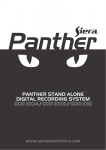
Crestron FT-PWR-D & FT-PWR-D-LG
FlipTop Power Centers, Dual AC Outlets
Operations & Installation Guide
This document was prepared and written by the Technical Documentation department at:
Crestron Electronics, Inc.
15 Volvo Drive
Rockleigh, NJ 07647
1-888-CRESTRON
Regulatory Compliance
This product conforms to UL STD 962A; certified to CSA STD C22.2 No. 21.
As of the date of manufacture, the FT-PWR-D and FT-PWR-D-LG have been tested and found to comply with
specifications for CE marking and standards per EMC and Radiocommunications Compliance Labelling.
Federal Communications Commission (FCC) Compliance Statement
This device complies with part 15 of the FCC Rules. Operation is subject to the following conditions:
(1) This device may not cause harmful interference and (2) this device must accept any interference received,
including interference that may cause undesired operation.
CAUTION: Changes or modifications not expressly approved by the manufacturer responsible for compliance
could void the user’s authority to operate the equipment.
NOTE: This equipment has been tested and found to comply with the limits for a Class B digital device,
pursuant to part 15 of the FCC Rules. These limits are designed to provide reasonable protection against harmful
interference in a residential installation. This equipment generates, uses and can radiate radio frequency energy
and, if not installed and used in accordance with the instructions, may cause harmful interference to radio
communications. However, there is no guarantee that interference will not occur in a particular installation. If
this equipment does cause harmful interference to radio or television reception, which can be determined by
turning the equipment off and on, the user is encouraged to try to correct the interference by one or more of the
following measures:
Reorient or relocate the receiving antenna
Increase the separation between the equipment and receiver
Connect the equipment into an outlet on a circuit different from that to which the receiver is connected
Consult the dealer or an experienced radio/TV technician for help
Industry Canada (IC) Compliance Statement
This Class B digital apparatus complies with Canadian ICES-003.
Cet appareil numérique de la classe B est conforme à la norme NMB-003 du Canada.
All brand names, product names and trademarks are the property of their respective owners.
©2010 Crestron Electronics, Inc.
Crestron FT-PWR-D & FT-PWR-D-LG
FlipTop Power Centers
Contents
FlipTop Power Centers, Dual AC Outlets: FT-PWR-D & FT-PWR-D-LG
1
Introduction ............................................................................................................................... 1
Features and Functions ................................................................................................ 1
Applications................................................................................................................. 2
Specifications .............................................................................................................. 3
Physical Description.................................................................................................... 4
Setup ........................................................................................................................................ 10
Installation ................................................................................................................. 10
Hardware Hookup ..................................................................................................... 16
Operation ................................................................................................................................. 17
Problem Solving ...................................................................................................................... 18
Troubleshooting......................................................................................................... 18
Further Inquiries ........................................................................................................ 18
Future Updates .......................................................................................................... 18
Return and Warranty Policies .................................................................................................. 19
Merchandise Returns / Repair Service ...................................................................... 19
CRESTRON Limited Warranty................................................................................. 19
Operations & Installation Guide – DOC. 6640C
Contents • i
Crestron FT-PWR-D & FT-PWR-D-LG
FlipTop Power Centers
FlipTop Power Centers, Dual AC
Outlets:
FT-PWR-D & FT-PWR-D-LG
Introduction
The FT-PWR-D and FT-PWR-D-LG FlipTop Power Centers provide an elegant
connectivity solution in a stylish flush mount tabletop package. Beneath the
"FlipTop" lid, the cable storage compartment keeps interface cables at the ready for
plugging in computers, AV sources, and a host of other devices. The
FT-PWR-D-LG’s larger size helps accommodate larger cables, connectors and
mounting surface cutouts.
For simplicity within this guide, FT-PWR-D/-LG is used, except where noted.
Features and Functions
•
•
•
•
•
Stylish flush-mount FlipTop housing
New larger size (FT-PWR-D-LG only)
Easy pull-out universal cable management
Two AC power outlets
Available in black anodized or brushed aluminum
The FT-PWR-D/-LG is available in two different sizes and finishes.
Models
DESCRIPTION
Dual AC Outlets
Dual AC Outlets, Large
MODEL NUMBER
COLOR
FT-PWR-D-B
Black Anodized
FT-PWR-D-BALUM
Brushed Aluminum
FT-PWR-D-LG-B
Black Anodized
FT-PWR-D-LG-BALUM
Brushed Aluminum
FlipTop Housing
Handsomely finished in either black anodized or brushed aluminum, the
FT-PWR-D/-LG mounts flush in any tabletop surface for a clean, discreet
appearance.
Operations & Installation Guide – DOC. 6640C
FlipTop Power Centers: FT-PWR-D & FT-PWR-D-LG • 1
FlipTop Power Centers
Crestron FT-PWR-D & FT-PWR-D-LG
Cable Storage Compartment
The FT-PWR-D/-LG provides for extensive connectivity through an easy pull-out
cable storage mechanism to support a wide range of applications and signal types.
Eight grommeted holes are provided in the bottom plate, allowing for smooth
pass-through of virtually any type of AV, communication, control, or data cable
(cables not included). When not in use, the user end of each cable stows neatly
within the FlipTop compartment while excess cable simply drops out-of-sight below
the box.
Dual AC Power Outlets
For complete connectivity, the FT-PWR-D/-LG includes two AC power receptacles
within the FlipTop compartment.
Applications
The following diagram shows an FT-PWR-D/-LG in a lecture hall application.
FT-PWR-D/-LG in a Lecture Hall Application
2 • FlipTop Power Centers: FT-PWR-D & FT-PWR-D-LG
Operations & Installation Guide – DOC. 6640C
Crestron FT-PWR-D & FT-PWR-D-LG
FlipTop Power Centers
Specifications
Specifications for the FT-PWR-D/-LG are listed in the following table.
FT-PWR-D/-LG Specifications
SPECIFICATION
DETAILS
Environmental
Temperature
41º to 104º F (5º to 40º C)
Humidity
10% to 90% RH (non-condensing)
Enclosure
Black painted metal with black anodized or
brushed aluminum cover; flush tabletop
mountable
Dimensions
FT-PWR-D
Height
5.39 in (137 mm) with lid closed
Width
6.75 in (171 mm)
Depth
5.71 in (145 mm) without mounting brackets
FT-PWR-D-LG
Height
5.76 in (146 mm) with lid closed
Width
7.67 in (195 mm)
Depth
6.55 in (166 mm) without mounting brackets
Weight
FT-PWR-D
3.8 lbs (1.7 kg)
FT-PWR-D-LG
5.5 lbs (2.5 kg)
Operations & Installation Guide – DOC. 6640C
FlipTop Power Centers: FT-PWR-D & FT-PWR-D-LG • 3
FlipTop Power Centers
Crestron FT-PWR-D & FT-PWR-D-LG
Physical Description
This section provides information on the connections, controls, and indicators
available on your FT-PWR-D/-LG.
FT-PWR-D Physical View
FT-PWR-D-LG Physical View
NOTE: Cables not included.
4 • FlipTop Power Centers: FT-PWR-D & FT-PWR-D-LG
Operations & Installation Guide – DOC. 6640C
Crestron FT-PWR-D & FT-PWR-D-LG
FlipTop Power Centers
FT-PWR-D Overall Dimensions (Top View)
5.08 in
(129 mm)
5.71 in
(145 mm)
6.75 in
(171 mm)
FT-PWR-D Overall Dimensions (Front View)
FT-PWR-D (Bottom View)
5.16 in
(131 mm)
6.25 in
(159 mm)
Operations & Installation Guide – DOC. 6640C
FlipTop Power Centers: FT-PWR-D & FT-PWR-D-LG • 5
FlipTop Power Centers
Crestron FT-PWR-D & FT-PWR-D-LG
FT-PWR-D Overall Dimensions (Rear View)
FT-PWR-D Overall Dimensions (Side View)
2.31 in
(59 mm)
4.31 in
(110 mm)
5.39 in
(137 mm)
4.63 in
(118 mm)
5.21 in
(132 mm)
6 • FlipTop Power Centers: FT-PWR-D & FT-PWR-D-LG
Operations & Installation Guide – DOC. 6640C
Crestron FT-PWR-D & FT-PWR-D-LG
FlipTop Power Centers
FT-PWR-D-LG Overall Dimensions (Top View)
6.00 in
(152 mm)
6.55 in
(166 mm)
7.67 in
(195 mm)
FT-PWR-D-LG Overall Dimensions (Front View)
FT-PWR-D-LG (Bottom View)
6.08 in
(154 mm)
7.17 in
(182 mm)
Operations & Installation Guide – DOC. 6640C
FlipTop Power Centers: FT-PWR-D & FT-PWR-D-LG • 7
FlipTop Power Centers
Crestron FT-PWR-D & FT-PWR-D-LG
FT-PWR-D-LG Overall Dimensions (Rear View)
FT-PWR-D-LG Overall Dimensions (Side View)
2.64 in
(67 mm)
4.75 in
(121 mm)
5.76 in
(146 mm)
5.51 in
(140 mm)
6.04 in
(153 mm)
FT-PWR-D/-LG (Front Face View)
1
8 • FlipTop Power Centers: FT-PWR-D & FT-PWR-D-LG
Operations & Installation Guide – DOC. 6640C
Crestron FT-PWR-D & FT-PWR-D-LG
FlipTop Power Centers
FT-PWR-D/-LG (Bottom View)
2
Connectors, Controls, & Indicators
#
CONNECTORS,
CONTROLS, &
INDICATORS
1
125V~50/60Hz 10A
(2) Grounded AC sockets,
AC power pass-through outlets;
Maximum load:
10 Amps (total) @ 120 Volts AC, 50/60 Hz
2
125V~50/60Hz 10A
(1) 9 foot grounded AC line cord;
passes through to front panel AC power
outlets
Operations & Installation Guide – DOC. 6640C
DESCRIPTION
FlipTop Power Centers: FT-PWR-D & FT-PWR-D-LG • 9
FlipTop Power Centers
Crestron FT-PWR-D & FT-PWR-D-LG
Setup
Installation
NOTE: To prevent overheating, do not operate this product in an area that exceeds
the environmental temperature range listed in the specifications table. Consideration
must be given if installed inside a closed desk or in a closed podium since the
operating ambient temperature of these environments may be greater than the room
ambient temperature. Contact with thermal insulating materials should be avoided on
all sides of the unit.
Use the following steps to install the FT-PWR-D/-LG.
Tools required
Cable Management Kit
•
Phillips screwdriver (not included)
•
Appropriate carpentry tools for cutout
The FT-PWR-D/-LG is shipped with a separate cable management kit for organizing
cables fed into the power center.
Parts Supplied for Cable Management Kit
DESCRIPTION
PART NUMBER
QUANTITY
Cable Support Plate (FT-PWR-D only)
2011563
1
Cable Support Plate (FT-PWR-D-LG only)
2013435
1
Bushings, 0.55 inch (14 mm) ID,
0.80 inch (2.03 cm) OD
2010496
2
Bushings, 0.39 inch (9.9 mm) ID,
0.64 inch (1.63 cm) OD
2011070
2
Bushings, 0.31 inch (7.9 mm) ID,
0.50 inch (12.7 mm) OD
2009522
4
Screws, #04-40 x 1/4" (6.4 mm)
2007158
4
The cable support plate should be installed before mounting the FT-PWR-D/-LG to a
surface. The cables are threaded through the cable support plate.
1.
Place bushings on the cables you wish to install in the power center (eight
bushings supplied). Use bushings appropriate for the diameter of each
cable.
2.
Thread the cables through the cable support plate slots appropriate for the
size of the cable and the bushing you attached in the previous step.
3.
Snap the bushings into the slots on the cable support plate.
4.
Feed all excess cable through the opening.
5.
Attach the cable support plate using the four #04-40 x 1/4" screws.
6.
If desired, any installed cables can be secured to the bottom bar with tie
wraps (not supplied).
10 • FlipTop Power Centers: FT-PWR-D & FT-PWR-D-LG
Operations & Installation Guide – DOC. 6640C
Crestron FT-PWR-D & FT-PWR-D-LG
FlipTop Power Centers
Cable Support Plate Installation
When selecting cables for installation in the FT-PWR-D/-LG, cable connector length
and strain relief diameter are important considerations.
•
If the connector is too long, it can interfere with cover operation.
•
If the width of the cable strain relief is too similar to the bushing inside
diameter, the bushing can trap the cable.
NOTE: Do not use the cable support plate without the bushings.
Example Cable End
Must be wider than the inside
diameter of the bushing.
Large Bushing: 0.54 in (14 mm)
Medium Bushing: 0.39 in (10 mm)
Small Bushing: 0.31 in (8 mm)
Must not be longer than
2.13 in (54 mm) to avoid
interference with cover
operation.
Operations & Installation Guide – DOC. 6640C
FlipTop Power Centers: FT-PWR-D & FT-PWR-D-LG • 11
FlipTop Power Centers
Crestron FT-PWR-D & FT-PWR-D-LG
Cables Threaded Through the Cable Plate
NOTE: Allow
approximately 40
inches clearance for
cables.
Cables passed through
cable support plate.
NOTE: Ensure that any cables you install have sufficient clearance to enable smooth
movement. Allow approximately 40 inches (~ 1 meter) from the top surface of the
FlipTop box.
Surface Mounting
The FT-PWR-D/-LG is designed to mount in a horizontal surface, such as a desk top,
lectern, or podium. The following diagram illustrates the required opening size to
accommodate the FT-PWR-D/-LG. Use the template supplied with the FT-PWR-D
or FT-PWR-D-LG (4010018 or 4007478, respectively) to make the cutout.
Cutout Dimensions for the FT-PWR-D (Not Actual Cutout Template)
6 3/8 in
(162 mm)
5 5/16 in
(135 mm)
MAXIMUM RADIUS
1/8 IN (4 MM)
12 • FlipTop Power Centers: FT-PWR-D & FT-PWR-D-LG
Operations & Installation Guide – DOC. 6640C
Crestron FT-PWR-D & FT-PWR-D-LG
FlipTop Power Centers
Example of the Cutout Dimensions for the FT-PWR-D-LG (Not Actual Cutout Template)
7 1/4 in
(184 mm)
6 1/8 in
(156 mm)
MAXIMUM RADIUS
1/8 IN (4 MM)
NOTE: Be sure to feed the attached power cord and all required cables through the
mounting hole before inserting the FT-PWR-D/-LG.
Mounting Parts Supplied
DESCRIPTION
PART
NUMBER
QUANTITY
Screws, #06-32 x 3/16”, Pan Head, Phillips
2007204
4
Screws, #10-32 x 2”, Pan Head, Phillips
2007293
4
Mounting Bracket
2013224
2
1.
Install the four supplied #06-32 x 3/16”screws (2007204) to the front of the
unit. Do not fully tighten the screws. These will be used to secure the front
mounting bracket. The four screws for the rear mounting bracket come
pre-installed from the factory. Refer to the illustration “Mounting Bracket
Screw Locations” on the following page.
2.
Position the FT-PWR-D/-LG in the mounting hole.
Operations & Installation Guide – DOC. 6640C
FlipTop Power Centers: FT-PWR-D & FT-PWR-D-LG • 13
FlipTop Power Centers
Crestron FT-PWR-D & FT-PWR-D-LG
Mounting Bracket Screw Locations
Screws (4)
#06-32 X 3/16"
(Pre-Installed)
Screws (4)
#06-32 X 3/16"
(2007204)
Surface
Cutout
3.
Thread a small portion of the #10-32 x 2” screws (2007293) into the
mounting brackets (two screws per bracket). Refer to the illustration on the
following page.
4.
Slide the mounting brackets over the #06-32 screws and tighten the
#06-32 screws.
14 • FlipTop Power Centers: FT-PWR-D & FT-PWR-D-LG
Operations & Installation Guide – DOC. 6640C
Crestron FT-PWR-D & FT-PWR-D-LG
FlipTop Power Centers
Mounting Bracket Installation
5.
Turn the four #10-32 screws equally until they contact the underside of the
mounting surface enough to secure the unit. DO NOT OVER-TIGHTEN.
CAUTION: Do not over-tighten the #10-32 screws as this may damage the surface
and/or the unit.
FT-PWR-D (Mounting Brackets Installed)
Operations & Installation Guide – DOC. 6640C
FlipTop Power Centers: FT-PWR-D & FT-PWR-D-LG • 15
FlipTop Power Centers
Crestron FT-PWR-D & FT-PWR-D-LG
FT-PWR-D-LG (Mounting Brackets Installed)
Hardware Hookup
Hookup consists of simply plugging the line cord into an appropriate outlet.
NOTE: The maximum continuous current from equipment under any external load
conditions shall not exceed a current limit that is suitable for the minimum wire
gauge used in interconnecting cables. The ratings on the connecting unit's supply
input should be considered to prevent overloading the wiring.
16 • FlipTop Power Centers: FT-PWR-D & FT-PWR-D-LG
Operations & Installation Guide – DOC. 6640C
Crestron FT-PWR-D & FT-PWR-D-LG
FlipTop Power Centers
Operation
The spring-loaded lid is opened by pressing briefly and releasing it. Cables are stored
neatly beneath the lid when not in use to keep out debris and dust. The lid opens 135
degrees, allowing full access to cables and power inside.
Beneath the lid, a recessed compartment with eight grommeted holes through the
bottom plate allows any type of AV, communication, data or control cables to be
instantly available for connection to your devices. The recessed compartment also
contains two three-pronged, grounded AC sockets.
Operations & Installation Guide – DOC. 6640C
FlipTop Power Centers: FT-PWR-D & FT-PWR-D-LG • 17
FlipTop Power Centers
Crestron FT-PWR-D & FT-PWR-D-LG
Problem Solving
Troubleshooting
The following table provides corrective action for possible trouble situations. If
further assistance is required, please contact a Crestron customer service
representative.
FT-PWR-D/-LG Troubleshooting
TROUBLE
POSSIBLE CAUSE(S)
Device connected
to the AC socket
is not working.
CORRECTIVE ACTION
Lack of, or insufficient,
power to AC socket.
Provide appropriate power to
the line cord.
Device is not receiving
power.
Check that plug is fully
inserted into AC socket.
Further Inquiries
If you cannot locate specific information or have questions after reviewing this
guide, please take advantage of Crestron's award winning customer service team by
calling Crestron at 1-888-CRESTRON [1-888-273-7876].
You can also log onto the online help section of the Crestron website
(www.crestron.com/onlinehelp) to ask questions about Crestron products. First-time
users will need to establish a user account to fully benefit from all available features.
Future Updates
As Crestron improves functions, adds new features and extends the capabilities of
the FT-PWR-D/-LG, additional information may be made available as manual
updates. These updates are solely electronic and serve as intermediary supplements
prior to the release of a complete technical documentation revision.
Check the Crestron website periodically for manual update availability and its
relevance. Updates are identified as an “Addendum” in the Download column.
18 • FlipTop Power Centers: FT-PWR-D & FT-PWR-D-LG
Operations & Installation Guide – DOC. 6640C
Crestron FT-PWR-D & FT-PWR-D-LG
FlipTop Power Centers
Return and Warranty Policies
Merchandise Returns / Repair Service
1.
No merchandise may be returned for credit, exchange or service without prior authorization
from CRESTRON. To obtain warranty service for CRESTRON products, contact an
authorized CRESTRON dealer. Only authorized CRESTRON dealers may contact the factory
and request an RMA (Return Merchandise Authorization) number. Enclose a note specifying
the nature of the problem, name and phone number of contact person, RMA number and
return address.
2.
Products may be returned for credit, exchange or service with a CRESTRON Return
Merchandise Authorization (RMA) number. Authorized returns must be shipped freight
prepaid to CRESTRON, 6 Volvo Drive, Rockleigh, N.J. or its authorized subsidiaries, with
RMA number clearly marked on the outside of all cartons. Shipments arriving freight collect
or without an RMA number shall be subject to refusal. CRESTRON reserves the right in its
sole and absolute discretion to charge a 15% restocking fee plus shipping costs on any
products returned with an RMA.
3.
Return freight charges following repair of items under warranty shall be paid by CRESTRON,
shipping by standard ground carrier. In the event repairs are found to be non-warranty, return
freight costs shall be paid by the purchaser.
CRESTRON Limited Warranty
CRESTRON ELECTRONICS, Inc. warrants its products to be free from manufacturing defects in materials
and workmanship under normal use for a period of three (3) years from the date of purchase from
CRESTRON, with the following exceptions: disk drives and any other moving or rotating mechanical
parts, pan/tilt heads and power supplies are covered for a period of one (1) year; touchscreen display and
overlay components are covered for 90 days; batteries and incandescent lamps are not covered.
This warranty extends to products purchased directly from CRESTRON or an authorized CRESTRON
dealer. Purchasers should inquire of the dealer regarding the nature and extent of the dealer's warranty, if
any.
CRESTRON shall not be liable to honor the terms of this warranty if the product has been used in any
application other than that for which it was intended or if it has been subjected to misuse, accidental
damage, modification or improper installation procedures. Furthermore, this warranty does not cover any
product that has had the serial number altered, defaced or removed.
This warranty shall be the sole and exclusive remedy to the original purchaser. In no event shall
CRESTRON be liable for incidental or consequential damages of any kind (property or economic damages
inclusive) arising from the sale or use of this equipment. CRESTRON is not liable for any claim made by a
third party or made by the purchaser for a third party.
CRESTRON shall, at its option, repair or replace any product found defective, without charge for parts or
labor. Repaired or replaced equipment and parts supplied under this warranty shall be covered only by the
unexpired portion of the warranty.
Except as expressly set forth in this warranty, CRESTRON makes no other warranties, expressed or
implied, nor authorizes any other party to offer any warranty, including any implied warranties of
merchantability or fitness for a particular purpose. Any implied warranties that may be imposed by law are
limited to the terms of this limited warranty. This warranty statement supersedes all previous warranties.
Trademark Information
All brand names, product names and trademarks are the sole property of their respective owners. Windows is a registered trademark
of Microsoft Corporation. Windows 95/98/Me/XP/Vista/7 and Windows NT/2000 are trademarks of Microsoft Corporation.
Operations & Installation Guide – DOC. 6640C
FlipTop Power Centers: FT-PWR-D & FT-PWR-D-LG • 19
Crestron Electronics, Inc.
15 Volvo Drive Rockleigh, NJ 07647
Tel: 888.CRESTRON
Fax: 201.767.7576
www.crestron.com
Operations & Installation Guide – DOC. 6640C
(2019709)
06.10
Specifications subject to
change without notice.