1
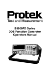
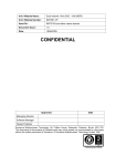
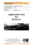
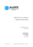
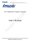
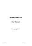
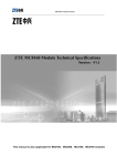
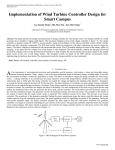
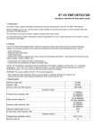
SMT391
User Manual
Version 1.5
Page 2 of 18
SMT391 User Manual
Revision History
Date
Comments
Engineer
Version
25/04/05
First release
JPA
1.0
15/07/05
Added information about on-board clocks.
JPA
1.1
31/08/05
Updated performances.
JPA
1.2
14/06/06
Errata: external trigger maximum frequency.
JPA
1.3
21/09/06
Added: weight characteristic
SM
1.4
28/09/06
Removed: DC-coupled version not supported
SM
1.5
Version 1.5
Page 3 of 18
SMT391 User Manual
Table of Contents
Revision History.......................................................................................................... 2
Table of Contents ....................................................................................................... 3
Introduction................................................................................................................. 4
Overview ................................................................................................................. 4
Module Features ..................................................................................................... 4
Possible Applications .............................................................................................. 4
Related Documents ................................................................................................ 5
Hardware overview..................................................................................................... 6
Block diagram ......................................................................................................... 6
ADC AT84AD001B ................................................................................................. 6
Main analogue features........................................................................................... 6
Inputs / outputs ....................................................................................................... 7
Clock structure ........................................................................................................ 8
Description of the Clock Tree .............................................................................. 9
SLB ......................................................................................................................... 9
Performances ........................................................................................................... 10
Introduction ........................................................................................................... 10
VCO Clock ............................................................................................................ 10
Components location................................................................................................ 12
Physical Properties................................................................................................... 14
Power Supply........................................................................................................ 14
Module Dimensions .............................................................................................. 15
Appendixes............................................................................................................... 16
SMT391 PCB View ............................................................................................... 16
SMT391 Assembly Drawings ................................................................................ 17
Test points location ............................................................................................... 18
Version 1.5
Page 4 of 18
SMT391 User Manual
Introduction
Overview
The SMT391 is a single width TIM module. It is capable of sampling two analogue
inputs at 1 GSPS with a resolution of 8 bits. An Atmel dual channel ADC
(AT84AD001) performs the analogue to digital conversion.
The SMT391 is a “Daughter-Module” that combines with a “base module” such as the
SMT338-VP.
Thanks to this configuration, all the analogue circuits are on the SMT391 (on the top)
and the digital circuits are on the base module (on the bottom). This allows reducing
the cross-talk, provide better separation and heat-dissipation.
The interface between the base module and the SMT391 is digital. It is implemented
using the Sundance LVDS Bus (SLB).
Module Features
The main features of the SMT391 are listed underneath:
•
Dual channel ADC (Ideal for I & Q channel applications)
•
1GHz sampling frequency
•
8 Bit data resolution
•
Custom Clock and Trigger inputs via external connectors
•
SLB connector to interface to the wide range of Sundance base modules
Possible Applications
The SMT391 can be used for the following applications (this non-exhaustive list
should be taken as an example):
•
Broadband cable modem head-end systems
•
3G Radio transceivers
•
High-data-rate point-to-point radios
•
Medical imaging systems
•
Spectrum analyzers
Version 1.5
Page 5 of 18
SMT391 User Manual
Related Documents
[1] Sundance LVDS Bus (SLB) specifications – Sundance.
http://www.sundance.com/docs/SLB%20-%20Technical%20Specifications.pdf
[2] Dual 8-bit ADC datasheet - Atmel.
http://www.atmel.com/dyn/resources/prod_documents/doc2153.pdf
Hardware overview
Block diagram
The following diagram represents the architecture of the SMT391 daughter module.
Base module
SLB connector
Control
AT84AD0001B
Dual 8-bits
1 Gsps
ADC
Control
Low jitter
local
oscillator
Clock
generation
and
distribution
External clock
Signal
conditionning
Signal
conditionning
Channel I
Channel Q
ADC AT84AD001B
Main analogue features
The main analogue characteristics of the SMT391 are listed in the following table:
Analogue inputs
Input voltage range
0.5Vp-p
Impedance
50Ω - terminated to ground
Analogue Bandwidth
ADC Bandwidth: 1500MHz
RF Transformer: 500kHz to 1.5GHz (AC
Coupled)
External sampling clock inputs
Signal format
LVPECL
Frequency range
Up to 1000 MHz
Version 1.5
Page 7 of 18
SMT391 User Manual
External trigger inputs
Signal format
LVPECL
Frequency range
Up to 25 MHz
SMT391 Output
Output Data Width
8-Bits
Data Format
Binary
ADC Performance @ FS = 1 GSPS, FIN = 500 MHz (from Atmel datasheet)
Spurious Free Dynamic Range (SFDR)
-54dBc
Signal to Noise and Distortion (SINAD)
45dB
Effective Number Of Bits (ENOB)
6.8 Bits
Total Harmonic Distortion (THD)
-51dB
Cross-talk channel I versus channel Q (Cr)
FIN = 250 MHz, FS = 1 GHz
< -65dBc
Figure 1 - Main features.
Inputs / outputs
The SMT391 is an AC-coupled mode.
The AC-coupled option uses a twisted pair balun (MACOM TP-101) transformer to
convert a single ended signal to a balanced AC Coupled input on the ADC. The
figure on the following page shows this setup. Note that the input on the ADC is
differential and that for each of these two signals there are two pads on the ADC.
One pad connects to the transformer and the second pad is terminated through a 50
Ohm resistor to ground.
R1
TP101
Input
Connector
R1
Version 1.5
Page 8 of 18
SMT391 User Manual
Figure 2 – AC-coupled Analogue Input stage.
Clock structure
There is an integrated clock generator (PLL+VCO clock or synthesized clock) on the
module. The user can either use this clock or provide the module with an external
clock (input via MMBX connectors, one for each channel).
External Clock
Module Clock
External Clock Input
(MMBX)
PLL
Voltage Controlled
Oscillator
Comparitor
LVPECL
Buffers
TTL to LVPECL
4:2 Mux with Dual Output
Clock
Div 8
Ch B Clock
Ch A Clock
ADC
LVDS
SerDes
Clock
RSL
Clock
DLL
Sys
Clock
DLL
FPGA
Diagram Key:
500 MHz LVDS Clock
125 MHz LVPECL Clock
1000 MHz LVPECL Clock
Clock
Control
Version 1.5
Page 9 of 18
SMT391 User Manual
Figure 3 – Module Clock Structure.
Description of the Clock Tree
The main clock source of the module is a UMC 600MHz to 1200MHz voltage
controlled oscillator. The frequency range of the VCO is adjustable with a National
PLL. The output of the VCO + PLL combination is passed through a Maxim high
frequency comparator with an LVPECL output to form the main system clock. In
addition to this clock there is a clock synthesizer on the module that can generate a
50 to 950 MHz clock. This clock is ideal for testing purposes. Alternatively the user
can provide the module with an external LVPECL clock – one input for each channel.
The clock synthesiser does not provide a clock as clear as the VCO does. Therefore
the performances of the module degrade when using the clock synthesiser.
The FPGA controls the LVPECL multiplexers that choose the final clock (clock
synthesizer, PLL+VCO, or external). A copy of this clock is fed to each channel of the
ADC. Another copy is divided by 8 (to give a 125MHz LVPECL clock) and fed into the
FPGA. (In the current firmware implementation this copy of the clock is not used by
the firmware design. The two clocks originating from the ADC is used by the design.
This clock can also only be the VCO or the synthesizer clock, not one of the external
clocks.)
The ADC clock determines the sampling rate of the ADC. The ADC buffers and
divides this clock by two (or four) to provide a 500MHz LVDS clock for each demultiplexed data channel (or a 250MHz DDR clock depending on the way the ADC is
configured). These two clocks are used to clock the ADC data into the FPGA.
When data is transmitted over the RSL links there must be a reference clock on the
receiving module that is closely matched in frequency to the transmitting clock. This
is important to insure that there will be no data over or under run. Due to this
requirement data can only be transmitted over the RSL interface when the on-board
VCO clock is used.
All clock circuitry is implemented on the daughter card. The four clocks that enter the
FPGA are passed down from the daughter card to the main module. An additional
125MHz oscillator is located on the main module. This oscillator is used as the
system clock for the FPGA design.
SLB
The SMT391 connects to a base module (for example a SMT338-VP) via the SLB
connector. Refer to the SLB specification document for more information.
Version 1.5
Page 10 of 18
SMT391 User Manual
Performances
Introduction
The following figures show data captures using the SMT391-VP to capture the data
and MATLAB to plot and display it. As the SMT391-VP is a broadband converter no
type of band-pass filtering were used when capturing these results. FFT Spurs might
thus seem high at certain points, but in a specific system application selective signal
filtering will significantly increase the quality of the captured signal. The analogue
input signal used is also not derived from the same clock source as the sampling
clock. There is thus also no frequency coherence, which will once again add
additional spurs to the FFT.
VCO Clock
The following figures show captures of the performance of the SMT391 onboard
VCO clock. This data was measured at the point where this clock is distributed to the
FPGA. The 1000MHz clock is split, one side goes to the ADC, and the other side is
divided by 8 (giving a 125MHz clock) and then passed on to the FPGA.
Figure 4 – FFT of Div 8 Version of 1000MHz System Clock.
Version 1.5
Page 11 of 18
SMT391 User Manual
Figure 5 – Time View of Div 8 Version of 1000MHz System Clock.
Figure 6 – Measured Results of the Clock.
Version 1.5
Page 12 of 18
SMT391 User Manual
Components location
The following diagram indicates the location of all the important connectors and
components on the SMT391 (Rev 2) PCB. This specific diagram is for an AC-coupled
analogue input stage using a Macom transformer.
Figure 7 – Connector Location on SMT391 (Rev 2 PCB, AC Coupled).
Diagram
Ref
Pcb
RefDes
Description
Notes
A
J9
External Trigger I Channel
LVPECL Signal. Positive on inside of connector. Negative on
outside of connector.
E
J10
External Trigger Q Channel
LVPECL Signal. Positive on inside of connector. Negative on
outside of connector.
B
J3
External Clock I Channel
LVPECL Signal. Positive on inside of connector. Negative on
outside of connector.
F
J4
External Clock Q Channel
LVPECL Signal. Positive on inside of connector. Negative on
outside of connector.
C
J1
ADC I Channel Input
Analogue signal input for ADC Channel I. Signal on inside of
connector. Analogue ground on outside of connector.
G
J2
ADC Q Channel Input
Analogue signal input for ADC Channel Q. Signal on inside
of connector. Analogue ground on outside of connector.
D
J8
Analog Test Signal
Analogue output test signal. Variable between 200 and
350MHz. Signal on inside of connector, Analogue ground on
outside of connector. Use a 1:1 RF cable to connect J8 to
either J1 or J2 for easy verification of the working of the
ADC.
Figure 8 – Table of Connector Locations on SMT391.
Version 1.5
Diagram
Ref
Page 13 of 18
Pcb
RefDes
Description
SMT391 User Manual
Notes
H
JP2
FPGA JTAG Connector
FPGA on SMT338-VP JTAG Chain. Only routed down to
SMT338-VP. Use for easy access without having to remove
the SMT391.
K
JP1
MSP JTAG Connector
MSP430 on SMT338-VP JTAG Chain. Only routed down to
SMT338-VP. Use for easy access without having to remove
the SMT391.
L
U1
Atmel Dual ADC
ADC Requires heat-sink with air-flow cooling in a system
setup
I
VCO1
UMC 600 – 1000MHz VCO
Main Clock source for SMT391. VCO Requires heat-sink
with air-flow cooling in a system setup.
I
VCO2
UMC 200 – 350MHz VCO
Test Clock for testing the analogue input of the ADC. VCO
Requires heat-sink with air-flow cooling in a system setup.
J
TRANS1
M/A Com TP101 Transformer
The SMT391 analogue input is AC-coupled through a
twisted pair balum transformer (single ended to differential).
J
TRANS2
M/A Com TP101 Transformer
The SMT391 analogue input is AC coupled through a twisted
pair balum transformer (single ended to differential).
Figure 9 – Table of Component Locations on SMT391.
Version 1.5
Page 14 of 18
SMT391 User Manual
Physical Properties
Dimensions
Weight
40 g.
Supply Voltages
Supply Current
+12V
+5V
+3.3V
-5V
-12V
MTBF
Power Supply
The following voltages are required by the SMT391 and must be supplied over the
daughter card power connector.
Voltage
D+3V3_IN
Current Required
2.0 A
D+5V0_IN
500 mA
D+12V0_IN
250 mA
D-12V0_IN
250 mA
DGND
Figure 10 – SMT391 Power Supply Voltages.
The following voltages are required by the SMT391-VP and must be supplied over
the TIM connectors and TIM mounting hole
Voltage
D+3V3_IN
Current Required
4.0 – 6.0 A
D+5V0_IN
4.0 A
D+12V0_IN
500 mA
D-12V0_IN
500 mA
DGND
Figure 11 – SMT391-VP Power Supply Voltages.
Version 1.5
Page 15 of 18
SMT391 User Manual
The following table lists the internal SMT391 voltages that are derived from the
voltages that are provided over the daughter card power connector.
Voltage
D+3V3
D+2V25
A+3V3
VCO+5V0
VCO+12V0
ECL-5V2
AGND
Description
Derived from D+3V3_IN
Derived from D+3V3 on SMT391
Derived from D+3V3_IN
Derived from D+5V0_IN
Derived from D+12V0_IN
Derived from D-12V0_IN
Derived from DGND
Figure 12 – Internal Power Supply Voltages.
Module Dimensions
The following table lists the dimensions for the SMT391 and the SMT391-VP.
Description
Module Dimensions (Only SMT391)
Module Dimensions (SMT391-VP)
Weight
Value
Width: 63.5 mm
Length: 106.68 mm
Height: 21mm (Maximum)
Width: 63.5 mm
Length: 106.68 mm
Height: 21mm (Maximum)
TBD Grams (including heat sinks)
Figure 13 – SMT391-VP Dimensions.
Version 1.5
Page 16 of 18
Appendixes
SMT391 PCB View
The following figures show the top and bottom view of the SMT391.
Figure 14 – SMT391 Top View.
SMT391 User Manual
Version 1.5
Page 17 of 18
SMT391 User Manual
Figure 15 – SMT391 Bottom View.
SMT391 Assembly Drawings
The following figures show the top and bottom assembly drawings of the SMT391.
Figure 16 – SMT391 Top Assembly Drawing.
Version 1.5
Page 18 of 18
SMT391 User Manual
Figure 17 – SMT391 Bottom Assembly Drawing.
Test points location
The following figure shows the location of the voltage test points on the SMT391.
Figure 18 – Voltage Test Point Locations.