1
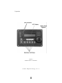
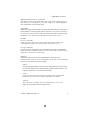
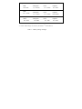
ME Series
Inverter / Chargers
Operator’s Manual
IMPORTANT SAFETY INSTRUCTIONS
This manual contains important safety instructions that must me followed during the
installation and operation of this product.
To reduce the risk of electrical shock, fire, or other safety hazard, the following safety symbols
have been placed throughout this manual to indicate dangerous and important safety instructions.
WARNING - Indicates a dangerous voltage or condition exists.
CAUTION - Indicates a critical ste p necessary for the safe installation and
operation of this device.
NOTE - Indicates an important statement. Follow these instructions closely.
ATTENTION - Electrostatic Sensitive Devices. Observe precautions for
handling.
All electrical work must be pe rformed in accordance with local, state
and federal electrical codes.
Read all instructions and safety information contained in this manual before
installing or using this product.
This product is designed for indoor / compartment installation. It must not be exposed to rain,
snow, moisture or liquids of any type.
Use insulated tools to reduce the chance of electrical shock or accidental
short circuits.
Remove all jewelry such as rings, watches, bracelets, etc., when installing or
performing maintenance on the inverter.
Always disconnect the batteries or energy source prior to installing or performing maintenance on the inverter.
Live power may be present at more than one point since an inverter utilizes both batteries and
AC.
Always verify proper wiring prior to starting the inverter. There
are no user serviceable parts contained in this product.
SAVE THESE INSTRUCTIONS
i
Ó 2003 - Magnum Energy, Inc.
IMPORTANT
BATTERY SAFETY INSTRUCTIONS
Wear eye protection such as safety glasses when working with batteries.
Remove all jewelry such as rings, watches, bracelets, etc., when installing or performing
maintenance on the inverter.
Never work alone. Always have someone near you when working around batteries.
Use proper lif ting techniques when working with batteries.
Never use old or untested batteries. Check each battery's label for age, type and date code to
ensure all batteries are identical.
Batteries are sensitive to changes in temperature. Always install batteries in a stable environment.
Install batteries in a well ventilated area. Batteries can produce explosive gasses. For
compartment or enclosure installations, always vent batteries to the outside.
Provide at least one inch of air space between batteries to provide optimum cooling.
Never smoke when in the vicinity of batteries.
To prevent a spark at the battery and reduce the chance of explosion, always connect the cables to
the batteries first. Then connect the cables to the inverter.
Use insulated tools at a ll times.
Always verify proper polarity and voltage before connecting the batteries to
the inverter.
To reduce the chance of fire or explosion, do not short-circuit the batteries
In the even of accidental exposure to battery acid, wash thoroughly with soap and water. In the
even of exposure to the eyes, flood them for at least 15 minutes with running water and seek
immediate medical attention.
Recycle old batteries.
SAVE THESE INSTRUCTIONS
ii
Ó
2003 - Magnum Energy, Inc.
Magnum Energy
ME Series Inverter / Chargers
Table of Contents
Section
Description
Page
1.
1.
2.
3.
4.
5.
Introduction
Features and Benefits
Standard Features
How an Inverter/Charger Works
Appliances and Run Time
The ME Series Inverter/Charger
1
1
1
3
3
5
2.
1.
2.
Installation
Unpacking and Inspection
Pre -Installation
Locating the Inverter
Locating Dedicated Batteries (optional)
Hardware / Materials Required
Tools Required
Wiring
AC Connections
DC Connections
AC Grounding
DC Grounding
Torque Requirements
AC Main Panel
Circuit Protection
Wire Routing
Installation
Inverter Mounting
Battery Installation
Battery Cables and Sizing
DC Wiring
DC Grounding
Negative Cable
Positive Cable
Battery Wiring
Parallel Connection
Series Connection
Series/Parallel Connection
DC Fuse Block
AC Wiring
AC Input (Shore Power) Routing
AC Input (Generator) Routing
Main AC Electrical Panel Routing
Wiring the Inverter AC Input
Wiring the Inverter AC Output
Final Inspection
7
7
7
7
7
8
8
8
8
8
8
8
9
9
9
9
11
11
11
12
12
12
12
12
13
13
15
15
17
19
19
19
19
21
21
21
3.
Ó
2003 - Magnum Energy, Inc.
iii
Table of Contents, continued
Section
2.
4.
Description
Page
Installation, continued
Options
Battery Temperature Sensor Installation and Wiring
R e m o t e C o n t r o l In s t a l l a t i o n a n d W i r i n g
AGS Module
Smart Shunt
Stacking Cable Kit
Start-up and Test
Connecting the Batteries to the Inverter
F i n a l I n s p e c t i o n a n d P o w e r-u p
Configuring the Inverter
25
25
25
25
25
25
26
26
26
27
3.
1.
Operation
Operating the Inverter
Search
Inverter Mode
AC Shore Power Mode
Bulk Charge Mode
Absorption Charge Mode
Float Charge Mode
Battery SaverTM M o d e
Fault or Alarm Conditions
Low Battery
High Battery
Overload
Overtemperature
28
29
29
29
29
29
29
29
29
31
31
31
31
31
4.
1.
Troubleshooting
Basic Troubleshooting
33
33
5.
1.
2.
Preventive Maintenance
Recommended Inverter and Battery Care
Off-Season Storage
34
34
34
6.
Specifications
35
7.
Warranty
36
5.
iv
Ó 2003 - Magnum Energy, Inc.
1. INTRODUCTION
1. Features and Benefits
Congratulations on your purchase of the ME Series inverter/charger from Magnum
Energy. The ME Series is a “new generation” inverter designed especially for rugged
recreational vehicle usage. Powerful, yet simple to use, the Magnum Energy inverter will provide you with
years of trouble-free performance so you can enjoy the all of the comforts you have come to expect from
your RV, all backed by our limited 3 year (36-month warranty).
The ME Series inverter is ETL Listed meeting the stringent requirements of UL458,
ensuring you the highest level of electrical safety and reliability.
Installation is easy. Simply connect the inverter’s output to your distribution circuits
or electrical panel; connect your shore power cable (AC) to the inverter’s easy-to-reach
terminal block; connect the batteries, and then switch on the power. Using the optional remote
control, you can easily operate your inverter from anywhere within your motor coach.
2. Standard Features
•
Four Power Models (ME1512RV, ME2012RV, ME2512RV and ME3012RV)
•
Shelf, Bulkhead or Upside Down Mounting
•
•
Modified Sine Wave Output
Power Factor Corrected Charger (Sine Wave)
•
•
RS485 Communication Port
Remote Port
•
•
Flash Programming
ON/OFF Inverter- mounted Switch with LED Indicator
•
•
50 Amp T ransfer (on Dual IN / Dual OUT Models)
Extra Large AC Access Cover with Terminal Screw Block
•
•
360 degree DC Connection Terminals with Covers
Battery Temperature Sensor - for optimum battery charging
•
•
•
Aluminum Cover
Smooth, Aesthetically Pleasing Design
ETL listed to UL/cUL 458
The following accessories are also available for ME Series products:
Remote Control - for convenient finger tip operation
AGS Module - automatically starts and stops your generator Smart Shunt
- provides precise voltage to DC current
Stacking Cable Kit - designed to accommodate dual inverter configurations
Ó 2003 - Magnum Energy, Inc.
1
1. INTRODUCTION
Figure 1
ME Series Inverter / Charger
Ó 2003 - Magnum Energy, Inc. 2
1. INTRODUCTION
3. How an Inverter/Charger Works
A n inverter takes direct current (DC) from your batteries and turns it into alternating
current (AC), exactly like you use at home. It also takes alternating current when your motor coach is
connected to shore power and transforms it into direct current to recharge your batteries.
There are two modes of operation associated with an inverter/charger: Inverter Mode:
Direct current (DC) from the vehicle’s batteries is transformed into alternating
current (AC) for use with you household electrical appliances.
Charger Mode:
Alternating current (AC) is taken directly from shore power (or other AC sources) and
passed directly to your household appliances. At the same time, the incoming AC is also converted
to DC to recharge the vehicle’s batteries.
4. Appliances and Run Time
The ME Series inverter/charger can power a wide range of household appliances
including small motors, hair dryers, clocks and other electrical devices. As with any
appliance using batteries for power, there is a certain length of time that it can run - t h i s i s c a l l e d “ r u n
time.” Actual run time depends on several variables including the size and the type of
appliance, the type of batteries installed in your recreational vehicle, as well as the battery’s
capacity and age. Other factors such as the battery’s state of charge and temperature can also affect the
length of time your appliances can run.
Appliances such as TVs, VCRs, stereos, computers, coffee pots, incandescent lights
and toasters can all be successfully powered by your inverter. Larger electrical appliances,
however, such as stoves, water heaters, etc., can quickly drain your batteries and are not recommended for
this application.
All electrical appliances are rated by the amount of power they consume. The rating is printed on
t h e p r o d uct’s nameplate label, usually located on its chassis near the AC power cord. Even
though it is difficult to calculate exactly how long an inverter will run a particular appliance, the
best advice is trial and error. Your ME Series inverter has a built - in s a f e g u a r d t h a t
automatically protects your batteries from over discharge.
NOTE: For optimum performance, a minimum battery bank of 200 AHr is
recommended.
Device
Load
Device
Load
Blender
Computer
Drill
Hot Plate
Light (Flo)
Microwave
400 W
300 W
500 W
1800 W
10 W
1000 W
Coffee Maker
Color TV
Hair Dryer
Iron
Light (Inc)
Refridgerator
1200 W
150 W
1000 W
1000 W
100 W
500 W
Table 1 - Typical Appliance Power Consumption Ó 2003 - Magnum Energy, Inc.
3
Power ON/OFF
Switch
1. INTRODUCTION
Charging / Inverting
LED
Stack Port M a g n u m
Net Port Remote
Port
Battery Temp Sensor Port
Figure 2
ME Series Inverter / Charger
Switch, LED and Connection Ports
Figure 3
ME Series Inverter / Charger
Electrical Connection Points
4
Ó 2003 - Magnum Energy, Inc.
1. INTRODUCTION
5. The ME Series Inverter/Charger
The ME Series inverter/charger is designed to allow easy access to wiring, circuit
breakers, controls and LED status indicator. Its die cast baseplate with one piece aluminum cover ensures
maximum durability with minimum weight, as well as cooler more efficient operation. The inverter is
equipped with the following features:
ON / OFF Switch - used to manually switch the inverter ON and OFF.
Green LED Indicator
• Medium flash (1 every 2 seconds)
Indicates connected loads are being powered from the batteries (inverting).
• Fast flash (1 per second)
Indicates “search” mode, conserving power when appliances are switched OFF.
• Solid
Indicates “bulk” charge when the batteries are low and the inverter is connected to shore power.
• Fast flash (1 per second)
Indicates “absorption” charge when the batteries are almost fully recharged and the
inverter is connected to shore power.
• Slow flash (1 every 8 seconds)
Indicates “float” charge when batteries are fully charged and the inverter is
connected to shore power.
• LED off
Indicates a “fault” condition such as low battery, overload or over temperature.
Remote Control Port - accepts connector for Magnum remote control cable. BTS
Port - accepts connector for remote battery temperature sensor cable.
MagnumNet Communication Port - accepts connector for Auto Gen Start or Smart Shunt (DC
current display) cable.
Positive Battery Terminal - provides 360 degree connection point for the positive (+)
cable from the vehicle’s batteries.
Negative Battery Terminal - provides 180 degree connection point for the negative () cable from the vehicle’s batteries.
Chassis Ground Connector - accepts chassis ground cable.
AC Access Cover - provides access to internal AC screw terminal connections. AC
Input Circuit Breaker - protects main AC (shore power) input circuit.
AC Output 1 Circuit Breaker (optional) - protects the primary AC output circuit (on
dual out units only).
AC Output 2 Circuit Breaker (optional) - protects secondary AC output circuit (on
dual out units only).
ME Series Nameplate Label - provides product and safety information.
Ó 2003 - Magnum Energy, Inc.
5
2. INSTALLATION
1. Unpacking and Inspection
Carefully remove the ME Series inverter from its shipping container and inspect all
contents. If items appear to be missing or damaged, contact Magnum Energy at (425) 353-8833 or your
authorized Magnum Energy dealer. If at all possible, retain the shipping container in the event the unit ever
needs to be returned for factory service.
ATTENTION: Electrostatic Sensitive Devices. Observe precautions for
handling.
2. Pre-Installation
Before installing the inverter, read all of the instructions and cautionary markings
contained in this manual.
NOTE: The inverter is heavy. Use proper lifting t echniques during installation to
prevent personal injury.
Locating the Inverter
The inverter must be mounted in a clean, dry, ventilated environment where the ambient temperatures
will not exceed 122 ºF (50 ºC). The location must be fully accessible and protected from exposure to heat
producing devices. You can mount t h e i n v e r t e r h o r i z o n t a l l y , v e r t i c a l l y o r u p s i d e -d o w n . I t m u s t
be securely fastened to a shelf, bulkhead, or other structural part.
Allow enough clearance to access the AC and DC connection po ints as well as the
inverter’s controls and status indicator. As with any inverter, it should be located as
close to the batteries as possible. Longer battery cable runs tend to loose efficiency and reduce the overall
performance of an inverter.
I f y o u a re p l a n n i n g t o i n s t a l l d e d i c a t e d b a t t e r i e s , o t h e r t h a n t h e v e h i c l e ’ s , m a k e sure
they are in a dedicated compartment that has ventilation to the outside. Also it is important that you never
mount the inverter directly above the batteries as they e m i t c o r r o s iv e f u m e s w h i c h c o u l d d a m a g e
the inverter’s electronics.
Locating Dedicated Batteries (optional)
Dedicated batteries must be mounted in a clean, dry, ventilated environment where they are protected
from high and low temperatures. The batteries must be mounted upright (if using liquid batteries) and
securely fastened to the vehicle. The l o c a t i o n m u s t b e f u l l y a c c e s s i b l e a n d p r o t e c t e d f r o m
exposure to heat producing devices.
To ensure optimum performance, a ventilated battery enclosure is recommended. The batteries should be
located as close as possible to the inverter. Longer battery c a b l e r u n s t e n d t o l o o s e e f f i c i e n c y a n d
r e d u c e t h e o v e r a l l p e r f o r m a n c e o f a n i n v e r t e r . Also, do not mount the batteries beneath the
inverter (or in the same compartment). B a t t e r ie s e m i t c o r r o s i v e f u m e s w h i c h c o u l d d a m a g e t h e
inverter’s electronics.
NOTE: For optimum performance, Magnum Energy recommends using AGM
( a b s o r b e d g l a s s m a t ) b a t t e r i e s s u c h a s L i f e l i n e TM b r a n d b a t t e r i e s .
CAUTION: Never locate dedicated batteries near the vehicle’s fuel tanks containing gasoline or
propane.
Ó 2003 - Magnum Energy, Inc.
7
2. INSTALLATION
2. Pre-Installation, continued
Hardware / Materials Required
Conduit, strain - r e l i e f s a n d a p p r o p r i a t e f i t t i n g s
1/4" mounting bolts and lock washers Electrical tape
Wire ties
Tools Required
Misc screw drivers
Drill and drill bits
Level
Level
Pliers
Pencil or Marker
1/2" wrench
Wire strippers
Multimeter
Wiring
Pre-plan the wire and conduit runs. For maximum safety, run both AC and DC wires/cabling in
(separate) conduit. Direct current wiring, due to its potential to generate RFI, should
be tied together with electrical tape. Wiring and installation methods must conform
to all applicable electrical codes.
NOTE: Run DC cabling in twisted pairs, keeping the runs as short as practical.
AC Connections
Use #10 AWG (or larger) THHN wire for all AC wiring. The inverter’s AC terminal
blocks accept up to #6 AWG wire.
DC Connections
Battery to inverter cabling should be only as long as required. If using #2/0 AWG
cables, do not exceed 5 feet (one way) for 12 VDC systems.
Crimped and sealed copper ring terminal lugs with a 5/16” hole should be used to c o n n e c t t h e
battery cables to the inverter’s DC terminals.
AC Grounding
T h e M E S e r i e s i n v e r t e r / c h a r g e r c o n t a in s a n i n t e r n a l n e u t r a l-t o -g r o u n d s w i t c h i n g
circuit for the AC electrical system.
WARNING: The AC shore power neutral must be grounded ONLY through the shore power cable. Do not
ground AC to the vehicle’s chassis.
DC Grounding
The inverter/charger should always be connected to a permanent, grounded w i r i n g s y s t e m . F o r t h e
majority of installations, the negative battery conductor is bonded to the vehicle’s
s a f e t y -g r o u n d i n g c o n d u c t o r ( g r e e n w i r e ) a t o n l y o n e p o i n t i n the system. The size for the
conductor is usually based on the size of the largest conductor in the DC system. DO NOT connect the
battery negative (- ) cable to the v e h i c l e ’ s s a f e t y g r o u n d . C o n n e c t i t o n l y t o t h e i n v e r t e r ’ s
n e g a t i v e b a t t e r y t e r m i n a l . I f t h e r e a r e a n y n o n -f a c t o r y i n s t a l l e d D C a p p l ia n c e s o n b o a r d
t h e v e h i c l e , D O N O T ground them at the safety ground. Ground them only at the negative bus of the
DC load center (as applicable).
Ó 2003 - Magnum Energy, Inc. 8
2. INSTALLATION
2. Pre-Installation, continued
Torque Requirements
Tor q u e a l l A C w i r i n g c o n n e c t i o n s t o 1 6 i n c h p o u n d s . T o r q u e D C c a b l e c o n n e c t i o n s to
10-12 foot pounds.
AC Main Panel
I f t h e i n s t a l l a t i o n w i l l b e p o w e r i n g a w i d e -r a n g e o f a p p l i a n c e s t h r o u g h o u t t h e vehicle,
an AC main panel is often recommended. This is simila r in appearance and f u n c t i o n a s y o u r h o m e ’ s
circuit breaker panel, providing an additional level of control and protection for the
various circuits. Always refer to electrical codes for safe wiring practices.
Circuit Protection
If using a AC main panel fo r distribution, always use breakers that provide the
correct ampere branch circuit protection in accordance with the National Electric
Code. The breakers must also be properly rated for the appliances that will be powered.
NOTE: Both AC and DC disconnects / overcurrent protection must be provided as part of
the installation.
Wire Routing
Determine all wire routes throughout the vehicle both to and from the inverter.
Conductors that are at risk to physical damage must be protected by conduit, tape, or pla c e d i n a
r a c e w a y . C o n d u c t o r s p a s s i n g t h r o u g h w a l l s , b u l k h e a d s o r o t h e r s t r u c tural members must be
protected to minimize insulation damage such as chafing. D u r i n g t h e i n s t a l l a t i o n , a l w a y s a v o i d
p l a c i n g c o n d u c t o r s n e a r s o u r c e s o f c h a f i n g caused by vibration or constant rubbing.
CAUTION: Always check for existing electrical, plumbing or other areas of potential damage prior to
making cuts in structural surfaces, bulkheads or walls.
Typical routing scenarios are:
AC Input wiring from the shore power source to the inverter
AC Input wiring from a generator (optional) to the inverter
DC Input wiring from the batteries to the inverter
AC Output wiring from the inverter to the coach’s AC main panel or to dedicated
circuits
Battery Temperature Sensor cable (optional) from the inverter to the batteries
Remote Control cable (optional) to the inverter
Ground wiring from the inverter to an external vehicle ground
Ó 2003 - Magnum Energy, Inc.
9
2. INSTALLATION
Mounting Screw
Placements
Figure 4
ME Series Inverter / Charger Base Plate
Inverter
ME1512
ME2012
ME2512
ME3012
DC Rating
150 amps
200 amps
250 amps
300 amps
@ 1 to 3 ft
@ 3 to 5 ft
@ 5 to 10 ft
#2/0 AWG
#4/0 AWG
#4/0 AWG
#2/0 AWG
#4/0 AWG
#4/0 AWG
#4/0 AWG
#4/0 AWG
#4/0 AWG
#4/0 AWG
#4/0 AWG
consult code
Table 2 - Recommended Battery Cable Sizing
10
Ó 2003 - Magnum Energy, Inc.
2. INSTALLATION
3. Installation
NOTE: Read all instructions and cautionary markings located at the beginning of this
m a n u a l a n d i n t h e p r e - i n s t a l l a t i o n s e c t i o n , b e f o re i n s t a l l i n g t h e i n v e r t e r a n d
batteries.
CAUTION: Do not mount the inverter or the batteries near the vehicle’s gasoline or propane fuel
tanks.
Mount the inverter only on a “non-combustable” surfaces. Maximum abient temperature
MUST NOT exceed 113 °F (45 °C).
For Canadian installations, the inverter’s vents must face downward.
Inverter Mounting
Position the inverter in the designated mounting location horizontally, vertically or
upside-down. Allow enough clearance to access the AC and DC connection points as w e l l a s t h e
inverter’s controls and status indicator. Also allow for air flow in to and around the
inverter, especially near the cooling fans (approximately 3”).
Mark the mounting holes in the base of the inverter’s chassis. Remove the in v e r t e r a n d d r i l l
pilot holes into the mounting surface.
Secure the inverter to the mounting surface using appropriate screws and lockwashers.
Remove the inverter’s AC access panel in accommodate the AC Input and Output wiring and
conduit.
Battery Installation
NOTE: To ensure the best performance from your inverter system, do not use old or untested batteries.
Batteries must be of the same size, type, rating and age.
NOTE: For optimum performance, Magnum Energy recommends using AGM
( a b s o r b e d g l a s s m a t ) b a t t e r i e s s u c h a s L i f e l i n e TM b r a n d b a t t e r i e s .
NOTE: If using Flooded Lead Acid batteries, they must be mounted upright.
CAUTION: Install batteries in a well ventilated area. Batteries can produce explosive
gasses. For compartment or enclosure installations, always vent batteries to the outside.
Place the batteries as close as practical to the inverter, preferably in an insulated
and ventilated enclosure. Allow adequate space above the batteries (+/- 6” above the batteries) to access
the terminals and vent caps (as applicable). Also allow at least 1” of space between the batteries to provide
good air flow. DO NOT mount the b a t t e r i e s d i r e c t l y u n d e r t h e i n v e r t e r .
Secure the batteries to the mounting surface with battery hold down clamps.
Ó 2003 - Magnum Energy, Inc.
11
2. INSTALLATION
3. Installation, continued
Battery Cables and Sizing
Select the correct battery cables for the installation from the table. It is important to use the correct
cable to achieve maximum efficiency from the system and reduce fire hazards associated with overheated
cables. Undersized cables can also l o w e r t h e i n v e r t e r ’ s p e a k o u t p u t v o l t a g e a s w e l l a s r e d u c e
its surge power capability. Long cable runs also reduce efficiency due to resistance in
t h e c a b l e . A l w a y s k e e p your cable runs a short as practical.
Battery cables must be color coded with colored tape or heat shrink tubing: RED f o r p o s i t i v e ( + ) ;
BLACK for negative ( -) ; a n d G R E E N f o r D C g r o u n d .
The cables must have soldered and crimped lugs, crimped copper compression l u g s , o r a l u m i n u m
mechanical lugs. Soldered connections alone are not acceptable for this application.
DC Wiring
Refer to the safety information at the beginning of the manual before proceeding. DC
w i r e s a n d c a b l e s s h o u l d b e t i e d t o g e t h e r w i t h w i r e t i e s o r e l e c t r i c a l t a p e a p p r o x i mately
every 6 inches.
WARNING: De -energize all sources of power including batteries ( D C ) , shore power ( A C ) , and AC
generator (if applicable).
CAUTION: Inverter is NOT polarity protected. Verify proper polarity BEFORE connecting the battery
cables.
NOTE: DO NOT connect the battery cables to the inverter until all wiring is complete
and the correct DC voltage and polarity has been verified.
NOTE: Make sure cables have a smooth bend radius and do not become kinked. P l a c e l o n g c a b l e r u n s
in conduit and follow existing wire runs where possible.
DC Grounding
Route a grounding cable (GREEN) from the inverter’s ground lug to a dedicated
vehicle ground.
Negative Cable
R o u t e a n e g a t i v e c a b l e ( B L A C K ) f r o m t h e h o u s e b a t t e r y b a n k ( o r d e d i c a t e d b a t tery
compartment) to the inverter’s negative terminal
Positive Cable
Route a positive cable (RED) from the house battery bank (or dedicated battery compartment) to the
Fuse Block assembly (DC Disconnect). The DC disconnect is usually located next to or near the batteries.
DO NOT connect the positive cable to the batteries at this time.
Route a positive cable (RED) from the Fuse Block assembly (DC Disconnect) to
the
inverter’s positive terminal DO NOT connect the positive cable to the inverter at this
time.
12
Ó 2003 - Magnum Energy, Inc.
2. INSTALLATION
3. Installation, continued Battery
Wiring
WARNING: During the installation and wiring process, cover exposed battery cable ends with electrical
tape to prevent shorting the cables.
NOTE: DO NOT connect the positive cable to the inverter at this time.
Depending upon the type of battery you use in the installation (6 or 12 VDC), the b a t t e r i e s m u s t b e
w i r e d i n s e r i e s , p a r a l l e l o r s e r i e s / p a r a l l e l t o p r o v i d e 1 2 V D C . T h e interconnecting battery
cables must be sized and rated exactly the same as those that used to connect the inverter.
When connecting the cable to the battery terminal, hardware should be installed i n t h e f o l l o w i n g
o r d e r : b o l t , r i n g w a s h e r , c a b l e l u g , ( b a t t e r y t e r m i n a l ) , r i n g w a s h e r , lock washer, nut.
Tighten terminal connections to at least 10 to 12 foot pounds.
When two cables are connected to a terminal (i.e., negative terminal), the hard ware should be
installed in the following order: bolt, ring washer, DC negative cable lug, inverter
negative cable lug, (battery terminal), ring washer, lock washer, nut.
Parallel Connection
(multiple 12 VDC batteries to create a 12 VDC string)
A parallel connection combines overall battery capacity by the number of batter ies in
the string. Even though there are multiple batteries, the voltage remains the same. In the example on the
next page (Figure 7), four, 12 VDC, 100 AHr batteries a r e c o m b i n e d i n t o a s i n g l e s t r i n g ,
resulting in a 12 VDC, 400 AHr bank.
Connect the negative battery terminals together using short cables. Connect the
positive battery terminals together using short cables.
Connect the negative battery cable (BLACK) from the inverter to the negative
terminal of the end battery. At the same time, connect a DC ground cable between t h e n e g a t i v e
terminal and the vehicle’s DC grounding bus.
C o n n e c t t h e p o s i t i v e ( R E D ) b a t t e r y c a b le from the inverter to the positive termi nal of
the battery at the opposite end of the string. This is essential to ensure even charging and discharging
across the entire battery string.
N O T E : A f u s e m u s t b e p l a c e d b e t w e e n t h e p o s i t i v e t e r m i n a l a n d t h e p o sitive (RED)
battery cable to the inverter.
Once the batteries are completely wired and tested, coat the terminals with an a p p r o v e d a n t ioxidizing spray.
Nut - Washer - Lug - Terminal - Washer - Bolt
Figure 5
Battery Hardware Installation
Ó 2003 - Magnum Energy, Inc.
Nut - Washer - Lug - Inverter Terminal
Figure 6
Inverter Hardware Installation
13
2. INSTALLATION
+
+
+
+
+
12 VDC
12 VDC
12 VDC
12 VDC
-
-
-
-
>
TO 12 VDC
INVERTER
>
Figure 7
Parallel Battery Wiring
individual battery capacity = 100 AHr @ 12 VDC
combined battery capacity = 400 AHr @ 12 VDC
- >
Figure 8
Series Battery Wiring
individual battery capacity = 200 AHr @ 6 VDC combined
battery capacity = 200 AHr @ 24 VDC
>
+
6 VDC
+
6 VDC
-
+
6 VDC
-
+
+
6 VDC
-
TO 12 VDC
INVERTER
>
Figure 9
Series/Parallel Battery Wiring
individual battery capacity = 200 AHr @ 6 VDC
combined battery capacity = 400 AHr @ 12 VDC
14
Ó 2003 - Magnum Energy, Inc.
2. INSTALLATION
3. Installation, continued
Series Connection
(four 6 VDC batteries to create a 24 VDC bank)
A s e r i e s c o n n e c t i o n c o m b i n e s o v e r a l l b a t t e r y v o l t a g e b y t h e n u m b e r o f b a t t e r i e s in
the string. Even though there are multiple batteries, the capacity remains the same. In the example at the
left (Figure 8), four 6 VDC, 100 AHr batteries are comb i n e d i n t o a s i n g l e s t r i n g r e s u l t i n g i n a 2 4
VDC, 200 AHr bank.
Connect the negative battery terminal of one battery to the positive of the other using a short cable.
C o n n e c t t h e n e g a t i v e b a t t e r y c a b l e ( B L A C K ) f r o m t h e i n v e r t e r t o t h e o p e n n e g a tive
terminal of one of the batteries. At the same time, connect a DC ground cable b e t w e e n t h e n e g a t i v e
terminal and the vehicle’s DC grounding bus.
C o n n e c t t h e p o s i t i v e b a t t e r y c a b l e ( R E D ) f r o m t h e i n v e r t e r t o t h e p o s i t i v e t e r m i nal of
the opposite battery.
NOTE: A fuse must be placed between the positive terminal and the positive (RED)
battery cable to the inverter.
Once the batteries are completely wired and tested, coat the terminals with an a p p r o v e d a n t ioxidizing spray.
Series/Parallel Connection
(four 6 VDC batteries to create a 12 VDC bank)
A series/parallel connection increases both voltage and capacity using smaller,
lower-voltage batteries. In the example at the left (Figure 9) four 6 VDC, 200 AHr b a t t e r i e s a r e
combined into two pairs resulting in a 12 VDC, 400 AHr bank.
Connect the negative battery terminal of one 6 VDC battery to the positive of the next (creating a pair)
using a short battery cable.
C o n n e c t t h e n e g a t i v e b a t t e r y t e r m i n a l o f a n o t h e r 6 V D C b a t t e r y t o t h e p o s i t i v e o f its
next using a short battery cable (creating a second pair).
Connect the remaining negative battery terminal of the first pair to that of the second pair using a
short battery cable.
Connect the remaining positive battery terminal of the first pair to that of the
second pair using a short battery cable.
Connect the negative battery cable (BLACK) from the inverter to the end battery’s
negative terminal. At the same time, connect a DC ground cable between the negat i v e t e r m i n a l a n d t h e
vehicle’s DC grounding bus.
Connect the positive battery cable (RED) from the inverter to the opposite end
battery’s positive terminal.
N O T E : A f u s e m u s t b e p l a c e d b e t w e e n t h e p o s it i v e t e r m i n a l a n d t h e p o s i t i v e ( R E D )
battery cable to the inverter.
Once the batteries are completely wired and tested, coat the terminals with an a p p r o v e d a n t ioxidizing spray.
Ó 2003 - Magnum Energy, Inc.
15
2. INSTALLATION
In - l i n e f u s e
~
+
+
+
> +
+
12 VDC
12 VDC
12 VDC
12 VDC
-
-
-
-
TO 12 VDC
INVERTER
>
Figure 10
Parallel Battery Wiring - Fuse Placement
Figure 11
Series Battery Wiring - Fuse Placement
+
+
+
>
+
In - l i n e f u s e
~
+
6 VDC
6 VDC
-
6 VDC
-
>
6 VDC
-
-
TO 12 VDC
INVERTER
Figure 12
Series/Parallel Battery Wiring - Fuse Placement
16
Ó 2003 - Magnum Energy, Inc.
>
2. INSTALLATION
3. Installation, continued
DC Fuse Block
A fuse or circuit breaker must be located within 18 inches of the battery to protect the DC wiring
system. The device must be rated to match the size of the cable, but can be rounded up to the next larger
size (i.e., a cable rated at 150 amps can accept a 175 amp fuse) as necessary.
Mount the fuse block (or circuit breaker assembly) as near as practical to the batteries.
Remove the fuse (or open the circuit breaker) and connect a short cable (same rating as the battery
cables) to one end of the fuse block.
Connect the short cable to the positive battery terminal.
Connect the positive cable (RED) fro m the inverter to the assembly. DO NOT
connect the positive cable to the inverter at this time.
Securely tighten the fuse block’s lugs. Once the entire installation is complete,
reinsert the fuse into the fuse block before connecting the positive cable to the
inverter.
Conductor Size
#2 AWG
#2/0 AWG
#4/0 AWG
Rating (conduit)
Rating (free air)
Breaker
Fuse
115 A max
170 A max
N/A
200 A
175 A max
265 A max
DC175
300 A
250 A max
360 A max
DC250
400 A
Table 3 - DC Fuse Rating
Ó 2003 - Magnum Energy, Inc.
17
2. INSTALLATION
DC Chassis
Ground
Figure 13
ME Series Inverter / Charger - AC Wiring
AC Output 2 Circuit Breaker
(on dual output models only)
AC Output 1 Circuit Breaker
(on dual output models only)
Figure 14
ME Series Inverter / Charger - AC Wiring (Access Panel)
18
Ó 2003 - Magnum Energy, Inc.
2. INSTALLATION
3. Installation, continued AC Wiring
WARNING: De -energize all sources of power including batteries ( D C ) , shore power ( A C ) , and AC
generator (if applicable).
AC wiring must be performed by a qualified person or licensed electrician.
DO NOT connect the inverter’s output to an AC power source.
WARNING: Risk of electric shock. Use only the ground-fault circuit interrupter [receptacles(s) or circuit
breaker(s)] specified in the installation and operating instructions manual supplied with the
inverter. Other types may fail to operate properly when con nected to this inverter
equipment.
Ground-fault circuit interrupters must be installed in the vehicle’s wiring system
to protect all branch circuits.
CAUTION: DO NOT place AC cabling in the same conduit with DC cabling.
NOTE: Read all instructions and cautionary markings located at the beginning of
this manual and in the pre -installation section, before installing the inverter
and batteries.
The minimum wire size for all ME Series models must be #10 AWG. The i n s t a l l e r m u s t
provide the appropriate circuit protection for the wire size used.
Refer to appropriate electrical codes for wire sizing and circuit protection.
AC Input (Shore Power) Routing
Route a 30 amp service (shore power) to the inverter. If the installation
i n c l u d e s a generator, route a 30 amp service (shore power) to an approved selector switch and then to the
main AC panel.
AC Input (Generator) Routing
Route a 30 amp service (generator) to an approved selector switch and then to t h e m a i n A C
electrical panel.
Main AC Electrical Panel Routing
Route the AC Output from the inverter’s internal terminal block to the 30
a m p breaker in the sub panel.
Inverter
ME1512
ME2012
ME2512
ME3012
Power Rating
Input Breaker
Input Wiring
Output Wiring
1500 VA
30 A
#10 AWG
#10 AWG
2000 VA
30 A
#10 AWG
#10 AWG
2500 VA
30 A
#10 AWG
#10 AWG
3000 VA
30 A
#10 AWG
#10 AWG
Table 4 - Recommended AC Wire Ratings for 120 VAC Applications
Ó 2003 - Magnum Energy, Inc.
19
2. INSTALLATION
Figure 15
ME Series Inverter / Charger - AC Wiring Diagram
(located on back of cover plate)
Figure 16
ME Series Inverter / Charger - AC Terminal Block
20
Ó 2003 - Magnum Energy, Inc.
2. INSTALLATION
3. Installation, continued
Wiring the Inverter AC Input (refer to diagrams on the following pages) Remove the chassis AC
access cover to access the internal terminal block.
Route the cable and conduit from the main panel, approved bypass selector switch or main
AC panel to the inverter’s AC INPUT conduit clamp. Tighten
the clamp securely on the conduit. Always leave a little extra slack in the wiring.
Connect the hot wire (BLACK) from the main panel’s dedicated 30 amp breaker to the
“AC INPU T (HOT 1 IN)” terminal. Tighten the screw terminal to 16 inch-p o u n d s .
NOTE: If using dual inputs, connect the RED wire from the main panel to AC INPUT
(HOT 2 IN)
Connect the neutral (WHITE) from the main panel’s neutral bus bar to the “AC
INPUT (NEU)” terminal. Tighten the screw terminal to 16 inch-p o u n d s .
Connect the ground (GREEN) wire from the main panel’s neutral bus bar to the “GROUND”
terminal. Tighten the terminal to 16 inch-p o u n d s .
Wiring the Inverter AC Output (refer to diagrams on the following pages) Route the cable and
conduit from the AC distribution panel to the inverter’s AC OUTPUT conduit clamp.
Tighten the clamp securely on the conduit.
Connect the hot (BLACK) wire to the “AC OUTPUT 1 (HOT)” terminal. Tighten the
terminal to 16 inch-pounds.
NOTE: If using dual outputs, connect the RED wire to the “AC OUTPUT 2 (HOT)”
terminal.
Connect the neutral (White) wire to the “AC OUTPUT (NEU)” terminal. Tighten the
terminal to 16 inch-pounds.
Connect the ground (Green) wire to the “GROUND” termin a l . T i g h t e n t h e t e r m i nal to
16 inch-pounds.
Final Inspection
Verify all cables / conduit runs are secured with wire ties or other nonconductive
fasteners to prevent chafing or damage from movement and vibration.
Verify strain reliefs or grommets are in place to prevent damage to the wiring or conduit where it
passes through walls, bulkheads or other openings.
Verify all AC connections are correct and torqued to 16 inch pounds.
Replace the covers on the main electrical / distribution panel. Replace
t h e chassis access cover.
Verify the inverter’s front panel switch is in the "OFF" position.
NOTE: If required by code, have the installation inspected by an electrical inspector.
Ó 2003 - Magnum Energy, Inc.
21
Figure 17a
Typical Wiring - Single IN / Single OUT (120 VAC)
Figure 18a
Typical Wiring - Single IN / Dual OUT (120 VAC)
Figure 19a
Typical Wiring - Dual IN / Dual OUT (120 VAC / 240 VAC)
22
Ó 2003 - Magnum Energy, Inc.
2. INSTALLATION
Inverter/Charger
AC Sub-panel
AC Main
Breaker Panel
AC Input Wiring
30 Amp
AC Output Wiring
Air Conditioning
Water Heater
Microwave
Outlets
30 Amp Outlet
TV / Entertainment
Inverted Outlets
Figure 17b
Typical Wiring - Single IN / Single OUT (120 VAC)
Figure 18b
Typical Wiring - Single IN / Dual OUT (120 VAC)
Figure 19b
Typical Wiring - Dual IN / Dual OUT (120 VAC / 240 VAC)
Ó 2003 - Magnum Energy, Inc.
23
2. INSTALLATION
Stack Port M a g n u m
Net Port Remote
Port
Battery Temp Sensor Port
Figure 20
ME Series Inverter / Charger - Option Connection Ports
24
Ó 2003 - Magnum Energy, Inc.
2. INSTALLATION
4. Options
Battery Temperature Sensor Installation and Wiring
Attach the ring terminal end of the Battery Temperature Sensor to the negative battery terminal.
Route the sensor’s cable to the inverter following existing wire runs.
Connect the cable to the BTS port on the inverter’s chassis.
Remote Control Installation and Wiring
Mount the remote control in a convenient location using four mounting screws
(refer to the ME Series Remote Control Operator’s Manual).
Route the cable to the inverter following existing wire runs.
Connect the cable to the remote port on the inverter’s chassis. AGS Module
future option - a v a i l a b l e s o o n Smart
Shunt
future option - a v a i l a b l e s o o n Stacking
Cable Kit
future option - a v a i l a b l e s o o n
25
Ó 2003 - Magnum Energy, Inc.
2. INSTALLATION
5. Start-up and Test
Connecting the Batteries to the Inverter
After all electrical connections have been completed, connect the batteries to the
inverter to begin the start-up process.
CAUTION: Verify correct battery voltage and polarity before connecting the cables to the inverter.
Replace the fuse or (close the breaker) at the DC disconnect.
Remove the electrical tape from the cable lugs and verify 12 VDC at the cable
connectors using a multimeter. Verify correct polarity: Black is negative (- ); Red is
positive (+).
Connect the negative (BLACK) battery cable to the inverter’s negative terminal. The
cable lug must be flush to the terminal’s surface. Place a lock washer and nut over the lug and torque the
connection to 10 to 15 foot pounds.
NOTE: There may be a spark (and audible snap) when the cable lug first contacts the inverter’s positive
terminal. Th is is a normal condition.
Connect the positive (RED) battery cable to the inverter’s positive terminal. The cable
lug must be flush to the terminal’s surface. Place a lock washer and nut over the lug and torque the
connection to 10 to 15 foot pounds.
Verify all cables and connectors are properly secured.
Place the red and black terminal covers on the inverter’s DC connector. Secure the covers with
enclosed hardware.
If the batteries are in an enclosure, perform a final check of the hold down brackets and all connections.
Close and secure the battery enclosure.
Final Inspection and Power-up
Prior to starting the inverter, make sure all connected appliances are switched
OFF or disconnected from the AC receptacles.
Use a multimeter to verify 12 VDC at the inverter’s DC connectors.
Switch the inverter power switch to ON. The inverter’s LED will flash indicating
DC power and the start -up sequence.
NOTE: When using the remote control, the inverter’s ON/OFF switch is disabled in
Charge mode.
V e r i f y t h e b r e a k e rs on the distribution panel are switched ON.
Use a true RMS multimeter to verify 120 VAC at the coach’s AC outlets. Connect the inverter to shore
power and switch the main circuit breaker ON. Verify the inverter’s LED switches from
INVERTER to AC IN (SHORE POWER). Use a true RMS multimeter to verify 120 VAC at each
of the coach’s AC outlets. Switch the Shore Power OFF. Verify the inverter’s LED switches
to inverter mode.
26
Ó 2003 - Magnum Energy, Inc.
2. INSTALLATION
Configuring the Inverter
The ME Series inverter/charger must be configured for Low Battery Cutoff (LBCO),
Shore Power Current, Charger Amps, Battery Size and Battery Type. These
operational parameters must be configured using the optional remote control.
Refer to the ME Series Remote Control operator’s manual to configure the following
parameters:
Shore (5, 10, 15, 20, 30, 50)
AGS OFF
Enable
Meter DC
AC
Setup Search
LBCO
Battery Bank
Battery Type
Charge Rate
Contrast
Factory Reset
Tech Temps Fault
Record
The ME Series inverter/charger also allows you to select an equalize charge for
the batteries. Press and hold the Charger ON/OFF switch for 4 seconds. The Equalize (EQ) function will
be initiated (and the correct code will be sent to the remote.) The EQ function
automatically terminates after 4 hours of operation. You can also manually stop the
equalize mode by pressing and holding the Charger ON/OFF switch while the inverter is in
EQ mode.
Table 5 - Factory Default Settings
Function
Search
LBCO
Battery Bank
Battery Type
Charge
Rate
Contr a s t
Ó 2003 - Magnum Energy, Inc.
Default
5 watts 11
VDC
400
AHr
Liquid Lead Acid
100 %
75 %
27
3. OPERATION
Charging / Inverting
LED
Figure 21
ME Series Inverter / Charger - LED Indicator
28
Ó 2003 - Magnum Energy, Inc.
3. OPERATION
1. Operating the Inverter
The ME Series inverter/charger has two modes of operation: INVERTER (providing
power to your appliances from the batteries) and AC (running from shore power or a generator). Whenever
the inverter is in AC mode, it passes power directly to your appliances as well as recharges the batteries
using a 3-stage battery charger (Bulk, Absorption and Float). This approach to battery charging provides
rapid and complete charging cycles without placing undue stress on the batteries. Inverter operation is
fully automatic.
Search
With search mode enabled, the inverter pulses the AC output looking for an e l e c t r i c a l a p p l i a n c e
( t y p i c a l l y 5 t o 1 0 0 w a t t s , d e p e n d i n g u p o n t h e s e t t i n g y o u ’ v e selected). Whenever there is no
load detected, the inverter automatically goes into search mode (sleep) to minimize energy consumption.
During this time, the i n v e r t e r ’ s g r e e n L E D f l a s h e s ( f a s t ) t o i n d i c a t e S E A R C H m o d e . W h e n
a n a p p l i a n c e i s switched on inside the coach, the inverter recognizes the need for power and automatically starts the inverter
Inverter Mode
Whenever AC Shore Power is no longer sensed, the inverter automatically transfers to
b a t t e r y p o w e r w i t h n o i n t e r r u p t i o n t o y o u r a p p l i a n c e s . T h e i n v e r t e r ’ s g r e e n L E D flashes
once every 2 seconds (medium flash) to indicate it is running on battery p o w e r a n d p r o v i d i n g A C t o
the coach.
AC Shore Power Mode
Whenever AC Shore Power is sensed, the inverter automatically transfers to the
shore power with minimal interruption to your appli ances.
Bulk Charge Mode
Whenever the inverter is running on nominal AC Shore Power, it charges the
batteries. The inverter’s green LED stays ON (solid) to indicate the first stage of
charging. During bulk charging, the charger supplies the maximum amount of constant current to the
batteries. As the battery voltage rises to a set value (typically 14.1 VDC for GEL, 14.3 VDC for
A G M , a n d 1 4 . 6 V D C f o r l i q u i d l e a d a c i d ) , t h e c h a r g e r will then switch to the next charging
mode.
Absorption Charge Mode
As the inverter continues to run on nominal AC Shore Power, and the batteries have been successfully
bulk charged, the charger enters its second stage of charging. T h e i n v e r t e r ’ s g r e e n L E D f l a s h e s o n c e
e v e r y s e c o n d ( f a s t f l a s h ) t o i n d i c a t e a b s o r p t i o n charging for 1 - 3 hours depending upon battery
bank selection (refer to the ME Series Remote manual). The charger then switches to its final charging
mode.
Float Charge Mode
A s A C s h o r e p o w e r c o n t i n u e s , t h e i n v e r t e r ’ s g r e e n L E D f l a s h e s o n c e e v e r y 8 seconds
(slow flash) to indicate the third and final stage of charging. The batteries a r e h e l d a t t h e f l o a t v o l t a g e
(typically 13.6 VDC for GEL, 13.1 VDC for AGM, and 13.4 VDC for liquid lead acid) as
l o n g a s A C i s p r e s e n t a t t h e i n v e r t e r ’ s i n p u t . F l o a t c h a r g ing reduces battery g a s s i n g ,
m i n i m i z e s w a t e r i n g r e q u i r e m e n t s ( f o r f l o o d e d b a t t e r i e s ) and ensures the batteries are
maintained at optimum capacity.
Battery SaverTM Mode
D e s i g n e d t o k e e p b a t t e r i e s f u l l y c h a r g e d o v e r l o n g p e r i o d s ( s t o r a g e ) w i t h o u t drying
them out. Whenever the charger is in float for 4 hours with no DC loads r u n n i n g , t h e c h a r g e r w i l l
turn OFF. If the battery voltage drops below 12.5 VDC, the charger will automatically
initiate float mode to return them to a full charge.
Ó 2003 - Magnum Energy, Inc.
29
3. OPERATION
Figure 22
ME Series Inverter / Charger - Fault Conditions
Figure 23
Optional ME Series Remote Control - Fault Conditions
30
Ó 2003 - Magnum Energy, Inc.
3. OPERATION
1. Operating the Inverter, continued
Fault or Alarm Conditions
The inverter monitors the AC Shore Power, the batteries and itself. Whenever a c o n d i t i o n o c c u r s
t h a t i s o u t s i d e t h e n o r m a l o p e r a t i n g p a r a m e t e r s , t h e i n v e r t e r w i l l take the necessary steps to
protect your appliances, batteries or itself from damage.
Low Battery
Whenever the battery voltage reaches a low level, the inverter will initiate Low
Battery Cutoff (LBCO) which automatically shuts the inverter down, along with all
connected loads, to protect the batteries from over-discharge damage. The i n v e r t e r ’ s L E D t u r n s
OFF to indicate the fault condition.
High Battery
As the inverter is charging, it constantly monitors the batteries. In the event the battery voltage
a p p r o a c h e s t o o h i g h o f l e v e l , i t a u t o m a t i c a l l y t u r n s o f f t h e b a t t e r y charger to protect the
batteries from damage. The inverter’s LED turns OFF to i n d i c a t e t h e f a u l t c o n d i t i o n .
NOTE: High battery voltage may be caused by excessive voltage from the alternator,
solar panels or other external charging sources.
Overload
During inverter and AC Shore Power operat ion, the inverter monitors the AC and DC
c i r c u i t s . I n t h e e v e n t o f a s h o r t -c i r c u i t o r o v e r l o a d c o n d i t i o n , t h e i n v e r t e r w i l l s h u t
down. The inverter’s LED turns OFF to indicate the fault condition.
Overtemperature
During inverter operation, if the inverter becomes overheated, it will shut down to
p r o t e c t i t s e l f f r o m d a m a g e . T h e i n v e r t e r ’ s L E D t u r n s O F F t o i n d i c a t e t h e f a u l t c o n d it i o n .
Ó 2003 - Magnum Energy, Inc.
31
4. TROUBLESHOOTING
1. Basic Troubleshooting
T h e M E Se r i e s i n v e r t e r / c h a r g e r i s a f a i r l y s i m p l e d e v i c e t o t r o u b l e s h o o t . T h e r e
are only two active circuits (AC and DC) as well as a charging circuit. The
following chart is designed to help you quickly pinpoint the most common inverter
failures.
WARNING: De -energize all sources of power including batteries ( D C ) , shore power ( A C ) , and AC
generator (as applicable).
Symptom
Possible Cause
Recommended Solution
No output power.
Inverter LED is OFF.
No output power.
Inverter LED is OFF.
Inverter is switched OFF.
Switch the in verter ON.
Battery voltage is too low.
Check battery voltage, fuses,
breakers and cable connections.
High or low battery voltage.
Check the battery voltage at
the inverter's terminals.
Discharge or charge batteries.
Replace the batteries.
No output power.
Green LED is flashing.
Load is too small for search
mode circuit detection.
Reduce the search threshold
or defeat search mode.
Low output power.
Low batteries.
Check and recharge batteries.
Appliances turn OFF/ON.
Green LED is flashing.
Loose or corroded battery cables.
Clean and tighten all cables.
Low batteries.
Recharge or replace batteries.
Loose AC output connections.
Tighten AC output connections.
AC output voltage seems
too low when using a meter.
Wrong type of voltmeter used
(displays 80 VAC to 100 VAC).
Use a “true” RMS voltmeter.
Low surge power.
Low batteries.
Check and recharge batteries.
Battery cables are the
wrong length or gauge.
Verify recommended cable lengths
and gauges from the manual.
Replace cables as necessary.
Low charging rate
when connected to
shore power.
Charge rate set too low.
Adjust charge rate from remote.
Low AC voltage (< 90 VAC).
Check AC input wiring.
Low charging rate
when using a generator.
Generator output is too low
to power both load and charger.
Reduce the load.
Increase the generator’s RPMs.
Charger doesn’t charge.
Ó 2003 - Magnum Energy, Inc.
Loose or corroded battery cables.
Clean and tighten battery cables.
Defective batteries.
Replace batteries.
Wrong charger settings.
Adjust the charger settings.
Wrong AC input voltage.
Verify proper AC input
voltage and frequency.
33
5. PREVENTIVE MAINTENANCE
1. Recommended Inverter and Battery Care
T h e M E S e r i e s i n v e r t e r / c h a r g e r i s d e s i g n e d t o p r o v i d e y o u w i t h y e a r s o f t r o u b l e free
service. Even though there are no user-serviceable parts, it is recommended that every 6 months you
perform the following maintenance steps to ensure optimum performance and extend the life of your
batteries.
WARNING: Prior to performing these checks, switch both the AC and DC circuits OFF.
Visually insp e c t t h e b a t t e r i e s f o r c r a c k s , l e a k s , o r s w e l l i n g - r e p l a c e i f n e c e s s a r y
U s e b a k i n g s o d a t o c l e a n a n d r e m o v e a n y e l e c t r o l y t e s p i l l s o r b u i l d u p s Check and
tighten all battery hold down clamps
Clean and tighten (10 to 12 foot pounds) all battery terminals and connecting cables
Check and fill battery water levels (Liquid Lead Acid batteries only)
Check individual battery voltages (replace those that vary more than 0.3 VDC of
each other)
Check all cable runs for signs of chafing - replace if necessary
C h e c k t h e i n v e r t e r ’ s c o o l i n g v e n t s - clean as necessary
Check and tighten (16 foot pounds) the inverter’s internal AC terminal block
connections
2. Off-Season Storage
When placing the coach into seasonal storage, it is recommended that you perf o r m t h e f o l l o w in g t o
ensure the system is properly shutdown (or properly configured for seasonal storage).
This is especially important for maintaining the batteries.
Non-protected Storage
Perform the recommended maintenance steps above Fully
charge the batteries
Connect shore power and verify the breaker to the inverter is switched ON V e r i f y t h e
inverter is switched ON
Switch OFF all unnecessary AC and DC loads
Protected Storage
Perform the recommended maintenance steps above Fully
charge the batteries
Switch OFF all A C and DC loads
Verify the inverter is switched OFF
Remove shore power and disable the generator (if installed)
34
Ó 2003 - Magnum Energy, Inc.
6. SPECIFICATIONS
ME Series Specifications
ME2012
ME2512
ME3012
MODEL
ME1512
12 VDC
12 VDC
12 VDC
Input Voltage (nominal): Input
12 VDC 10.8-15.5
10.8-15.5 VDC
10.8 -15.5 VDC
10.8-15.5 VDC
Voltage (range): Power Rating @
VDC 1500 watts
2000 watts
2500 watts
3000 watts
45°C: Surge Rating: Rated Power: 3000 watts 119
4000 watts
5000 watts
6000 watts
Full Vo ltage: Search Mode:
amps 0.700 amps
158 amps
198 amps
238 amps
Short Circuit: Inverter
0.045 amps 238
0.900 amps
0.900 amps
0.900 amps
Efficiency: Charger
amps 94% max
0.055 amps
0.030 amps
0.030 amps
Efficiency: Charger (power
85% max > 0.95 0-
317 amps
396 amps
476 amps
factor): Charge Rate (adjustable):
70 amps 10-11.5
94% max
94% max
94% max
Battery Protection (variable):
VDC 35lb (16kg)
85% max
85% max
85% max
> 0.95
> 0.95
> 0.95
0-100 amps
0-120 amps
0-140 amps
10-11.5 VDC
10-11.5 VDC
10-11.5 VDC
38lb (17kg)
40lb (18kg)
45lb (20kg)
Unit Weight:
Common Specifications Output
Voltage:
120 VAC
Voltage Regulation (max):
±5% modified
Waveform:
sine 5 to 100 watts
Adjustable Load Sensing:
optional
Remote Control: Charging
liquid lead acid,
Profiles:
AGM, and GEL
Frequency Regulation:
Voltage Regulation (typ):
DC Load Disconnect
on/off
Sensing:
(high/low DC signal)
±2.5% 0 to 1
Power Factor:
30 amps at 120 VAC 50
Automatic Transfer Relay:
amps at 240 VAC bulk,
absorb,
Four Stage Charging:
variable speed fan
Forced Air Cooling:
60 Hz ± .04%
float
Battery Saver
TM
and
yes
optional pigtail
Temp Comp Probe:
(inverter on/off)
Remote Dry Contact:
240 VAC (future)
Series Operation:
Environmental Characteristics
Operating Ambient Temp:
-4 °F to +120 °F (-20 °C to +50 °C)
Max Altitude (operating):
15,000 feet (4.57 km)
Dimensions (HxWxD):
13.75” x 12.65” x 8” (34.9 cm x 32.1 cm x 20.3 cm)
Mounting:
shelf (top or bottom up) or bulkhead
Specifications @ 25 °C - Subject to change without notice
Ó 2003 - Magnum Energy, Inc.
35
7. WARRANTY
36 Month Limited Warranty
Magnum Energy, Inc., warrants the ME Series Inverter / Charger to be free from defects in
material and workmanship that result in product failure during normal usage,
according to the following terms a n d c o n d i t i o n s :
1. The limited warranty for the product extends for 36 months beginning from the product's original
date of purchase.
2. The limited warranty extends to the original purchaser of the product and is not assignable or
transferable to any subsequent purchaser.
3. During the limited warranty period, Magnum Energy will repair, or replace at Magnum
Energy's option, any defective parts, or any parts that will not properly operate for
their intended use with factory new or rebuilt replacement ite ms if such repair or
replacement is needed because of product malfunction or failure during normal usage. The
limited warranty does not cover defects in appearance, cosmetic, decorative or structural parts
o r a n y n o n -operative parts. Magnum Energy's limit of liability under the limited
warranty shall be the actual cash value of the product at the time the original purchaser returns
the product for repair, d e t e r m i n e d b y t h e p r i c e p a i d b y t h e o r i g i n a l p u r c h a s e r . M a g n u m
Energy shall not be liable for any other losses or damages.
4. Upon request from Magnum Energy, the original purchaser must prove the product's original
date of purchase by a dated bill of sale, itemized receipt.
5. The original purchaser shall return the product prepaid to Magnum Energy in Eve r e t t , W A .
Magnum Energy will return the product prepaid to the original purchaser after the
completion of service under this limited warranty.
6. This limited warranty is voided if:
• the product has been modified without authorization
•
•
•
the serial number has been altered or removed
the product has been damaged through abuse, neglect, accident, high voltage or corrosion.
the product was not installed and operated according to the owner's manual.
IN CASE OF WARRANTY FAILURE, CONTACT MAGNUM ENERGY INC. FOR A RETURN
AUTHORIZATION (RA) NUMBER BEFORE RETURNING THE UNIT FOR REPAIR.
1111 80th Street SW - Suite 250
Everett, WA 98203
p: 425.353.8833
f: 425.353.8390
36
Ó 2003 - Magnum Energy, Inc.
Remote Control
for ME Series
Inverter/Chargers
Operator’s Manual
Remote Control
for ME Series Inverter/Chargers
Table of Contents
Section
Page
1. Overview
2. Installation
2
3
3. Operation
4
Front Panel
5
Rotary Knob
5
Switches
5
Chart 1 - Battery Charge Voltages
6
Chart 2 - A b s orption Times
6
Chart 3 - Factory Default Settings
6
LEDs
8
LCD Display
9
4. Troubleshooting and Specifications
11
5. Warranty
12
SAVE THESE
Ó 2003 - Magnum Energy, Inc.
INSTRUCTIONS
This manual contains important
safety instructions.
1
1. Overview
IMPORTANT SAFETY INFORMATION
•
This product must be installed by a qualified technician in
accordance with all applicable electrical codes
•
Always disconnect the coach’s batteries before installing this
product
•
Remove the generator’s spark plug (or disconnect the battery on diesel
generators) to prevent accidental starting during installation of this product
•
Use insulated tools
Remote Control for ME Series Inverter/Chargers Congratulations on your
purchase of a remote control for your Magnum Energy inverter/charger. The
remote allows you to customize the operating parameters of the
inverter/charger, t h u s m a x i m i z i n g p e r f o r m a n c e a n d i n c r e a s i n g t h e
l i f e o f y o u r batteries.
The remote control has all of the programming and operation functions included
in an easy-to-use package. The remo te features soft keys as well as a rotary knob,
LEDs and a two-line L C D r e a d o u t .
To help save energy, the automatic power saver mode turns off a l l L E D s a s
w e l l a s t h e L C D d i s p l a y f i v e m i n u t e s a f t e r t h e l a s t soft key has been
pushed. The display will "wake up" with any keystroke or whenever a change in
operational status occurs.
Installing the remote control is a simple process and requires the following
tools:
• Phillips Screw Driver • Level • Drill
• 7/64” & 1/8” Drill Bits • Pencil
CAUTION: Always check for hidden wires, pipes and cables BEFORE
drilling or cutting into the coach’s walls, cabinets or bulkheads.
Ó 2003 - Magnum Energy, Inc.
2
2. Installation
Installing the ME Series Remote Control
1. Determine a suitable location to mount the remote control. It must be located in
a clean, dry and protected place.
Allow ample room to access the remote’s adjustment dial and to v i e w t h e
L E D s f o r t r o u b l e s h o o t i n g . P r e d r i l l t h e f o u r 1 / 8 ” h o l e s as necessary.
2. Route the 4 wire twisted pair wiring from the inverter/
charger to the remote. Connect the wiring to the rear of the remote and to the
remote port on the inverter/charger.
3. Use the four 6x3/4” screws to mount the remote to the coach’s wall
or bulkhead.
Figure 1
ME Series Remote Control
Ó 2003 - Magnum Energy, Inc.
3
3. Operation
Figure 2
Remote Control - Font Panel
Ó 2003 - M a g n u m E n e r g y , I n c . 4
3. Operation, continued
ME Series Remote Control - Front Panel
The remote control is equipped with a wide range of easy-touse switches
and displays, allowing you to quickly setup your inverter/charger as
well as determine its operational status.
Rotary Knob
The Rotary “spin” knob is similar to a dash radio knob and used to easily move
between menus to select program options. Turn t h e r o t a r y k n o b c lo c k w i s e
t o i n c r e a s e s e l e c t i o n s a n d c o u n t e rclockwise to decrease selections. Push
the knob to “save” the selection displayed in the LCD screen.
Switches
Inverter ON/OFF:
Used to switch the inverter function ON and OFF. The green
“INVERTER” LED turns ON and O F F w i t h t h e s w i t c h .
Charger ON/OFF:
Used to switch the charger function ON and OFF. The green “CHARGER”
LED turns ON and OFF with the switch. Press and hold the switch
down for 5 seconds to initiate EQ.
Soft Keys:
Press the soft keys to access the required function. Then use rotary
“SELECTOR” knob to scroll through the selections. Press the rotary
knob to save the selection. Options include:
Shore –
Sets the appropriate breaker size for the incoming shore power and is used
to control the amount of AC amps the battery charger uses from HOT 1 IN.
Selection options are 5,10,15,20,30 and 50 amps.
AGS –
Turns the optional AGS (Auto Gen Start) function ON and
OFF. Selection options are OFF, ENABLE and TEST.
Meters –
This function is display only and indicat e s D C v o l t s , D C
amps, AC volts (future) and AC amps (future).
Ó 2003 - Magnum Energy, Inc.
5
Liquid Lead Acid (Flooded)
Bulk
14.6 VDC
GEL
Bulk
14.1 VDC
Absorption
14.6 VDC
Float
13.4 VDC
Equalize
15.5 VDC
Absorption
1 4 . 1 VD C
Float
13.6 VDC
Equalize
Disabled*
Float
13.1 VDC
Equalize
15.5 VDC
AGM (Absorbed Glass Mat)**
Bulk
Absorption
14.3 VDC
14.3 VDC
* CAUTION: Never “Equalize” Gel batteries.
** NOTE: AGM voltages are courtesy of Lifeline
TM
brand batteries.
Chart 1 - Battery Charge Voltages
Chart 2 - Absorption Times
(determined by battery bank size selection)
Chart 3 - Factory Default Settings
Ó 2003 - M a g n u m E n e r g y , I n c .
Battery Size 200
AHr 400 AHr
600 AHr 800
AHr 1000 AHr
Function
Search
LBCO
Battery Bank
Battery Type
Charge
Rate
Contrast
6
Charge Time 90
minutes 120
minutes 150
minutes 180
minutes 210
minutes
Default
5 watts 1 0
VDC 400
AHr
Liquid Lead Acid
80 %
75 %
3. Operation, continued
Soft Keys, continued:
Setup –
Configures the inverter/charg er. Options include:
•
Search
Used to set the search watts at which the inverter will come out of “sleep”
mode. Selections are 3-75 watts.
•
LBCO (Low Battery Cut Out)
Used to set the DC voltage level to shut down the inverter and protect the
batteries from over-discharge damage. Selections are 9.0 VDC, 10.0
VDC and 11.0 VDC. DC volts must reach and maintain LBCO
setting for 1 minute before inverter shut down is initiated.
• Battery Size
Used to select the approximate battery bank capacity. Selections are in 200
amp increments from 200 -1000 amps. Battery capacity is also used to
determine absorption time during battery charging. See Chart 2.
• Battery Charge Rate
Used to set the maximum charge rate during bulk, absorption or float
charge. Selections are in 10 amp increments from 10% - 100%.
• Battery Type
Used to select battery type for the battery charge profile. Selections are
Gel, AGM (Absorbed Glass Mat), Liquid Lead Acid (Flooded) and
Custom (future). See Chart 1.
•
Contrast
Used to adjust the LCD contrast.
• AC Dropout Voltage
Used to select the AC voltage threshold (60, 90, 100 VAC) where the
inverter transfers from AC line to inverter mode.
• Tech – (display only)
Reserved for future, this feature is used for troubleshooting the
inverter/charger. Options in clude FET temp, transformer temp, and
battery temp.
Factory Reset
Restores all settings to factory defaults. press and hold the switch the switch
for 5 seconds. “Reset Complete” will be appear in the display. See Chart 3.
Ó 2003 - Magnum Energy, Inc.
7
3. Operation, continued
LEDs
The remote contains the following LEDs to indicate various
modes of operation.
PWR (green):
OFF - NO AC power from inverter, shore or generator at
inverter output terminals
ON - AC power available from inverter, shore or generator at
inverter output terminals
FAULT (red):
OFF - Normal operation
ON - Inverter or Charger shutdown from: Overtemperature (check tech
menu for exact cause), Low Battery Voltage (battery voltage
below LBCO setting or lower than 9.0 VDC, High Battery
Voltage (above 15.5 VDC), AC Overload (loads larger than
inv output capacity)
CHG (green)
OFF - Charger OFF, no shore or generator AC present
Fast Blink - AC present from shore or generator, synchroniz ing
to AC waveform before relay transfer
ON - Bulk, Absorb, Float ,Equalize or Battery Full Charge
mode
Slow Blink - Charger Standby (Charger off button was pressed with AC
available from shore or generator), Charger Backoff (charger
temperature too hot and charger automatically reduced charge rate to
maintain temperature), Low AC Input Voltage (Input voltage below 85 VAC.
Charger automatically disabled to help stabilize AC line voltage).
INV (green)
OFF - Inverter OFF
Slow Blink - Search Mode. AC load below the Search Watts setting
ON - Inverter ON and s upplying AC to output terminals
NOTE: When both the INV and CHG LEDs are "ON," the Inverter
is in standby mode. Shore or generator AC power is passed through the
inverter to the loads. If shore or generator power is lost, the inverter
automatically supplie s A C power to the loads.
Ó 2003 - Magnum Energy, Inc.
8
3. Operation, continued
LCD DISPLAY
INVERTING:
OFF Unit is “OFF” with no shore or generator AC power applied.
Search –
Unit is in search mode. AC loads are less than the search watts setting.
Inverting –
U n i t i s i n v e r t i n g p o w e r f r o m t h e b a t t e r i e s i n t o 1 2 0 V A C a t its
output.
CHARGING:
Bulk Charge –
The battery charger is delivering maximum current to the batteries. The
charger will remain in bulk charge until the bulk charge voltage is
achieved. See Chart 1.
NOTE: The maximum current can be reduced by adjusting the battery
charge rate and shore power settings using the setup options.
Absorption –
Absorption charge is the second stage of charging and indicates the bulk
voltage for battery type selected has been reached. The DC current will start
to taper off in order to maintain the bulk voltage setting. Absorption time is
determined by battery bank size selection. See Chart 2.
Figure 3
Menu Map
Ó 2003 - Magnum Energy, Inc.
Shore
5
10
15
20
30
50
AGS
Enable
OFF
TEST
METER
SETUP
TECH
GET TEMP ERATURES
Battery Temp Transformer
Temp FET Temp
SHOW VERSIONS
Remote V 0.xxx Inverter V
1.xxx
Adj Search Watts
5 - 75 Watts
LBCO
9 VDC
10 VDC
11 VDC
Batt AHr
200
400
600
800
1000
FACTORY RESET Push
and hold to reset to factory
default
Batt Type Charge Rate VAC Dropout Adjust Contrast Gel10 - 100%
60
VAC
0 - 100%
Liq Lead
80 VAC
AGM
100 VAC
9
3. Operation, continued
Float –
At the end of absorption time, the charger reduces the charge voltage to
the float voltage setting for the battery type selected. See Chart 1.
Battery SaverTM - “Battery Full”
Battery saver mode is a new and unique setting to Magnum Energy’s
inverter/chargers. It maintains the batteries without “overcharging” thus
preventing excessive loss of water in flooded batteries or drying
out of AGM batteries. After 4 hours in float mode, the charger is
switched OFF and “Battery Full” is indicated. When the battery voltage
drops to 12.9 VDC, the charger turns on and float charges the batteries to a
nominal level. Once that level has been reached, the charger returns to
“Battery Full” mode to monitor the batteries.
Equalize –
The battery charger is delivering equalize voltage to the
batteries for a maximum of 4 hours. See Chart 1. Press and hold the switch
down for 5 seconds to initiate EQ. The LED will blink fast.
NOTE: Equalize mode will not start until the charger is in float
or “Full Battery” mode.
10
Figure 4
Fault Conditions
Ó 2003 - Magnum Energy, Inc.
4. Troubleshooting and Specifications Fault Conditions
Low Battery –
The unit has shut down because the battery voltage is below the set
point in LBCO. It will automatically restart when battery
voltage rises above 12.5 VDC.
High Battery –
The unit has shut down because the battery voltage has exceeded 15.5
VDC. It will automatically restart when the battery voltage drops below
15.5 VDC.
Overtemp –
The unit has shut down because the temperature at the transformer or FET
board has exceed the safe temperature operating range. It will
automatically restart after unit cools down.
AC Overload –
The unit has shut down because the AC load connected to the inverter’s
output exceeded its maximum output rating.
NOTE: When this occurs, reduce the load and MANUALLY
restart the unit.
Specifications
Electrical Requirements 12 VDC
Controls
Charger (ON/OFF),
Inverter (ON/OFF)
LED Indicators
Power, Fault, Charger, Inverter
Soft Keys
Shore, AGS, Meter, Setup, Tech
Selector Switch
Rotary (press to accept)
Display
LCD (2 line)
Cable type
4 wire twisted pair
Weight
0.5 lb (0.22 kg)
Dimensions
3.75" H x 5.75" W x 1.125" D
(9.5 cm H x 16.6 cm W x 2.9 cm D)
Cutout Dimensions
2.75" H x 4.75" W (7 cm
H x 12 cm W)
Specifications at 25 °C - subject to change without notice.
Ó 2003 - Magnum Energy, Inc.
11
5. Warranty
36 Month Limited Warranty
Magnum Energy, Inc., warrants the ME Series Remote Control to be free from defects in material
and workmanship that result in product failure during normal usage, according to the
following terms and conditions:
1. The limited warranty for the product extends for 36 months beginning from the product's original
date of purchase.
2. The limited warranty extends to the original purchaser of the product and is not assignable or
transferable to any subsequent purchaser.
3. During the limited warranty period, Magnum Energy will repair, or replace at
Magnum Energy's option, any defective parts, or any parts that will not properly operate for their
intended use with factory new or rebuilt replacement items if such repair or replacement is needed
because of product malfunction or failure during normal usage. The limited warranty
does not cover defects in appearance, cosmetic, decorative or structural parts or any nonoperative parts. Magnum Energy's limit of liability under the limited warranty shall be
the actual cash value of the product at the time the original purchaser returns the product for
repair, determined by the price paid by the original purchaser. Magnum Energy shall not
be liable for any other losses or damages.
4. Upon request from Magnum Energy, the original purchaser must prove the product's original
date of purchase by a dated bill of sale, itemized receipt.
5. The original purchaser shall return the product prepaid to Magnum Energy in Everett, WA.
Magnum Energy will return the product prepaid to the original purchaser after the completion
of service under this limited warranty.
6. This limited warranty is voided if:
• the product has been modified without authorization
• the serial number has been altered or removed
• the product has been damaged through abuse, neglect, accident, high
voltage or corrosion.
• the product was not installed and operated according to the owner's manual.
IN CASE OF WARRANTY FAILURE, CONTACT MAGNUM ENERGY INC. FOR A
RETURN AUTHORIZATION (RA) NUMBER BEFORE RETURNING THE UNIT FOR
REPAIR.
Magnum Energy, Inc.
1111 80th Street SW - Suite 250
Everett, WA 98203
p: 425.353.8833
f: 425.353.8390
Ó 2003 - M a g n u m E n e r g y , I n c .
12
Magnum Service Manual
REV 1.0 12/03
INDEX
1.0
Troubleshooting
2.0
Repairing
2.1 Top Cover Removal 2.2
AC Board 2.3 AC Breakers
2.4 Fet Board 2.6 DC
Terminal Plate 2.7
Transformer 2.8 Fans
2.9 Remote
3.0
Test Procedure
1.0 TROUBLESHOOTING
1.1 ME SERIES 1.2
RD
SERIES
REMOTE
1.3
2.0 REPAIRING
OVERVIEW
1.1 TOP COVER REMOVAL
2.1.a Top cover is attached with 6 - #10 x 5/8 Torx screws (#25 bit) and 1- #6 x 1/2
Torx screw (#15 bit). Remove all seven screws and pull straight up to remove top cover.
2.2.a
2.2.b
Remove top cover per 2.1
Remove 4- #6 x ½ Torx screws from corners of ac board
2.2.c
Use a utility knife or sharp chisel to cut temp sensor loose then
clean remaining silicon from transformer.
2.2.d Mark and remove ac wires from ac board being careful to note
the start wire from the transformer location. Also note the
orientation of the black and orange wire. Miswiring of these
wires can lead to instant FET board failure upon connecting ac
power to the unit.
WIRING COLOR CODE:
White – Neutral IN (2 wires)
Black – AC Hot IN 1 Red – Hot
IN 2 Blue – Hot OUT 2
2.2.e Install wires to new ac board and install 4- #6 x ½ Torx screws.
2.2.f
Use silicon to glue down sensors to transformer in old location. Use tape
to temporarily hold sensors until silicon dries.
2.2.g Re-install Top Cover
2.3 AC BREAKERS
2.3.a Remove top cover per 2.1
2.3.b Remove 4- #6 x ½ Torx screws from corners of ac board and lift board slightly
(see 2.2 for screw location) 2.3.c Loosen knurled nut on breaker shaft and pull
breaker out
2.3.d Reinstall new breaker in reverse order 2.3.e
Reinstall Top Cover
2.4 CONTROL BOARD
2.4.a
2.4.b
Remove top cover per 2.1
Remove 2 - #6 x ½ Torx screws from lower L brackets in control board
2.4.c
Pull control board straight up to disconnect from FET board
2.4.d
Remove ribbon cable from control board. Note orientation of ribbon cable
on connector. (colored cable has brown wire facing rear, gray cable has
red wire facing rear).
2.4.e
Install new control board in reverse order making sure to line up connector on
board edge with FET board connector before pushing down on control
board.
2.4.f Re-install Top Cover
2.5.a
2.5.b
Remove top cover per 2.1
Remove 2- ¼ x 20 bolts and nuts from inside DC plate
2.5.c
Remove 2- #10 x ¾ Torx screws from outside DC plate
2.5.d
Pull firmly straight up to remove DC plate from base
2.5.e
Re-install DC plate in reverse order.
2.5.f
Re-install Top Cover
2.6 FET BOARD
2.6.a
2.6.b
Remove top cover per 2.1
Remove control board per 2.4
2.6.c
Remove DC Plate per 2.5
2.6.d Remove 2 - ¼ x 20 bolts and nuts from FET board wiring bundles to
transformer lugs
2.6.e
Remove 1 - #6 x ½ Torx screw from outside edge of FET board and
unplug fan connectors
2.6.f
2.6.g
Remove 4 - #10 x ¾ Torx screws from FET bar clamps
Pull up firmly on FET board to release from base and remove black
insulation material (Burquist)
2.6.h
Install new insulation material being careful to properly align with base
2.6.i
Loosely install 3- #6 x ½ screw to properly align FET board to base
2.6.j
Re-install FET bar clamps and alternately tighten 4- #10 x ¾ Torx screws
until all 4 screws are tightened to xxx
2.7.c
Use a utility knife or sharp chisel to cut temp sensor loose then
clean remaining silicon from transformer
2.7.d
2.7.e
Remove 4 corner Phillips head screws holding down transformer
Install new transformer being careful to align #10 nylon shoulder washers
into base while setting transformer in place. Make sure to install start wire
from transformer to correct terminal on ac board or damage will occur
to FET board when ac power is applied
2.7.f
Install 4 screws with nylon shoulder washers and tighten snug
2.7.g
Use silicon to glue down sensors to transformer in old location. Use tape
to temporarily hold sensors until silicon dries
2.7.h Reinstall Top Cover
2.6 FANS
2.8.a
2.8.b
Remove Top Cover per 2.1
Remove 1 - #6 x ½ Torx screw from fan bracket
2.8.c
Bend fan bracket upward to remove fan
2.8.d
Reinstall fan in reverse order
2.8.e
Reinstall Top Cover
2.9 REMOTE
2.8.a
2.8.b
Remove front knob (it may be necessary to pry slightly up on knob)
Remove 2 Phillips head screws from back of remote
2.8.c
Remove circuit board and keypad from case
2.9.d
Re-assemble in reverse order